EP1848366B1 - Procede de fabrication d'une prothese dentaire et appareillage mis en oeuvre - Google Patents
Procede de fabrication d'une prothese dentaire et appareillage mis en oeuvre Download PDFInfo
- Publication number
- EP1848366B1 EP1848366B1 EP06707948A EP06707948A EP1848366B1 EP 1848366 B1 EP1848366 B1 EP 1848366B1 EP 06707948 A EP06707948 A EP 06707948A EP 06707948 A EP06707948 A EP 06707948A EP 1848366 B1 EP1848366 B1 EP 1848366B1
- Authority
- EP
- European Patent Office
- Prior art keywords
- implant
- guide
- guide cylinder
- radiological
- analogue
- Prior art date
- Legal status (The legal status is an assumption and is not a legal conclusion. Google has not performed a legal analysis and makes no representation as to the accuracy of the status listed.)
- Expired - Lifetime
Links
Images



Classifications
-
- A—HUMAN NECESSITIES
- A61—MEDICAL OR VETERINARY SCIENCE; HYGIENE
- A61C—DENTISTRY; APPARATUS OR METHODS FOR ORAL OR DENTAL HYGIENE
- A61C13/00—Dental prostheses; Making same
-
- A—HUMAN NECESSITIES
- A61—MEDICAL OR VETERINARY SCIENCE; HYGIENE
- A61C—DENTISTRY; APPARATUS OR METHODS FOR ORAL OR DENTAL HYGIENE
- A61C1/00—Dental machines for boring or cutting ; General features of dental machines or apparatus, e.g. hand-piece design
- A61C1/08—Machine parts specially adapted for dentistry
- A61C1/082—Positioning or guiding, e.g. of drills
- A61C1/084—Positioning or guiding, e.g. of drills of implanting tools
-
- A—HUMAN NECESSITIES
- A61—MEDICAL OR VETERINARY SCIENCE; HYGIENE
- A61C—DENTISTRY; APPARATUS OR METHODS FOR ORAL OR DENTAL HYGIENE
- A61C1/00—Dental machines for boring or cutting ; General features of dental machines or apparatus, e.g. hand-piece design
- A61C1/08—Machine parts specially adapted for dentistry
-
- A—HUMAN NECESSITIES
- A61—MEDICAL OR VETERINARY SCIENCE; HYGIENE
- A61C—DENTISTRY; APPARATUS OR METHODS FOR ORAL OR DENTAL HYGIENE
- A61C8/00—Means to be fixed to the jaw-bone for consolidating natural teeth or for fixing dental prostheses thereon; Dental implants; Implanting tools
-
- A—HUMAN NECESSITIES
- A61—MEDICAL OR VETERINARY SCIENCE; HYGIENE
- A61C—DENTISTRY; APPARATUS OR METHODS FOR ORAL OR DENTAL HYGIENE
- A61C8/00—Means to be fixed to the jaw-bone for consolidating natural teeth or for fixing dental prostheses thereon; Dental implants; Implanting tools
- A61C8/0089—Implanting tools or instruments
-
- A—HUMAN NECESSITIES
- A61—MEDICAL OR VETERINARY SCIENCE; HYGIENE
- A61C—DENTISTRY; APPARATUS OR METHODS FOR ORAL OR DENTAL HYGIENE
- A61C2201/00—Material properties
- A61C2201/005—Material properties using radio-opaque means
Definitions
- the present invention relates to a method of manufacturing a dental prosthesis to be implanted in a jaw of a patient and to an apparatus used for such an implantation.
- This method has the great advantage of imagewise determining the position of each of the implants to be implanted in an ideal position in the jaw, depending on the situation of the mandibular nerves, sinuses, etc.
- it is reproducibly introduced into a model and subsequently in the same manner in the jaw an implant analog and a similar implant respectively. This introduction is always carried out so that the implant and the implant analog are fixed in their support (model or jaw) with the position determined on the images in two and three dimensions, that is to say with the same axial orientation and at the same depth.
- the head of the implant and that of the implant analog which generally have a triangular or polygonal section prism shape and on which the prosthesis is then placed, are rotated in a precise position which will be the same in both cases.
- This offers the exceptional advantage of being able to realize the final unitary or multiple prosthesis on model, even before the installation of the implants, and to set up this prosthesis on the implants, the day of the pose of these.
- these artificial teeth consist of a visible material in radiological imaging which, preferably, is a mixture of current resin for the shaping of artificial teeth and barium sulfate. This is introduced into the mixture for example in a proportion of the order of 30% by volume.
- the present invention also aims to provide an apparatus for dental implantation in a jaw of a patient, in particular an apparatus which is capable of implementing the method indicated above.
- dental prosthesis is meant according to the invention any apparatus intended to be placed on a dental implant, and in particular a crown, an abutment, a bar, a bridge, etc.
- each guide cylinder, on the one hand, and each analog holder or each implant holder to slide inside this guide cylinder, on the other hand have means reciprocating stops which stop a rotational movement of the analog carrier or implant holder relative to the guide cylinder in a predetermined position, these abutment means serving as first and second or respectively third external marks aforesaid.
- each guide cylinder has an axial cavity having an internal diameter
- each analog holder or implant holder or each second drill having a cylindrical portion having an external diameter allowing a guided sliding of this portion in the cavity of the guide cylinder and a flange having a diameter greater than said inner diameter, which serves as said stop means.
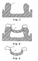
- FIGS. 1 to 8 represent in a sectional view the steps of manufacturing a surgical guide according to the invention.
- the figure 12 represents a side elevational view of a guide cylinder according to the invention.
- the figure 13 is a side elevational view of a similar holder according to the invention.
- the figure 14 represents a screw for fixing the implant analog to its analog holder.
- the figure 15 is a partially sectional view of the assembly of the implant analog and its analog holder.
- the figure 16 represents a drill to use in a model.
- model 1 is then made an accurate "wax-up" assembly using a mounting base 2 made of wax or resin and selected false teeth 3, which can be found on the market for example under the trademark Physiodens.
- This assembly must prefigure with precision the prosthetic result and it must therefore be tried in the mouth by the patient and possibly adapted (see figure 3 ).
- a key 4 for example silicone
- a mixture of a material used for the shaping of artificial teeth for example a synthetic resin, and of barium sulphate at about 30% by volume, is poured into the space left empty. is a visible material in radiological imaging. After hardening, a corresponding arc 5 is obtained (see figure 5 ).
- This radiological guide is terminated by unmolding it from the model 1, eliminating the undercuts on the intrados of the guide, and by applying radiological markers on them which allow a spatial positioning of the radiological guide inside the apparatus. imaging and tracking on the image obtained.
- a marker may for example consist of a lego block 28 (see figure 7 ) and / or gutta tips inserted into the guide at appropriate locations.
- the X-ray guide can then be tried again in the patient's mouth.
- a two-dimensional image of the radiological guide in position on the patient's jaw is taken in a suitable apparatus, for example by scanning into a scanner.
- the data from the scanner can for example be recorded on a disk, for example a CD, in DICOM mode.
- these data are processed to transform the two-dimensional image into a three-dimensional image.
- the computer is controlled by a suitable program, available on the market, for example the MED3D program distributed by Distridenta Sprl.
- a suitable program available on the market, for example the MED3D program distributed by Distridenta Sprl.
- these two- and three-dimensional images of course, there is a jaw, the mandibular nerve if it is the lower jaw, or a sinus if it is the upper jaw.
- These images also show the radiological guide in a low-contrast form as well as the radiological references.
- the artificial teeth thanks to their special composition, stand out very clearly and accurately by a brilliant white color, compared to the rest of the duller color image.
- the program makes it possible to select, for each tooth to be implanted, an implant of the type and dimensions (length, diameter) appropriate among the implants available on the market and recorded in the data of the computer.
- This implant can then be introduced in the form of a virtual image into the two and three dimensional images of the jaw in a surgically appropriate position.
- the implants are in fact placed virtually according to the position of the separated neighboring teeth, the occlusion, the nerve, the sinus, the bone. It is also verified that the amount of bone is sufficient to obtain osseointegration (1.5 mm) around the implant.
- the program also makes it possible to place virtually vertically, in the images of the radiological guide, guide rollers of a suitable height and diameter for the precise case, these parameters to be determined according to the top of the implant.
- the virtual guide cylinders are placed coaxially with the virtual implants.
- the computer records the setting coordinates of virtual implants and virtual guide cylinders in the two-dimensional and three-dimensional images in an electronically transmittable form.
- the aforementioned two-dimensional and three-dimensional image data is transmitted to an appropriate positioning and drilling tool capable of translating and using that data.
- an appropriate positioning and drilling tool capable of translating and using that data.
- an apparatus available on the market under the trade name MED3D distributed by Distridenta Sprl can be used.
- the radiographic guide 7, for example with plaster is then placed in the positioning tool according to the calculations of the computer.
- the positioning tool is capable of drilling holes 8 in each of the artificial teeth 6 of the radiological guide 7 (see figure 8 ), each hole being arranged and oriented as the virtual guide cylinder on the images in two and three dimensions.
- a guide cylinder 9 can then be placed in each hole, for example by means of a cylinder holder arranged on the positioning tool.
- FIG. figure 12 A guide cylinder embodiment of this type is shown in FIG. figure 12 .
- This guide cylinder is provided with an outer mark in the form of a notch 10 in its upper edge.
- This notch has a sloping face, which preferably has an inclination in the direction of the turns of the future implant and a stop face parallel to the axis of the cylinder.
- the cylinders are placed so that this mark is visible from the outside of the mouth when the surgical guide is in place in that of the patient. It should be understood that other types of mark can be imagined, and for example one or more markings on the upper edge of the cylinder.
- the cylinders 9 are fixed in their hole 8, for example by photopolymerization of a suitable composite material. The surgical guide is now ready for use and receives the reference 11.
- This surgical guide 11 is placed on a model 1. Drilled holes 16 are then drilled through the model, guided by the cylinders 9 of the surgical guide (see FIG. figure 8 ). Of course, to avoid damaging the cylinders 9 intended to guide the future surgical drilling in the mouth, protect them by a not shown protective cylinder and inserted inside the guide cylinders 9. This drilling can be carried out manually or through the positioning and drilling tool. A type of drill that can be used is shown, not to scale, on the figure 16 for example.
- the rod of this drill 12 is passed through a drill guide 13 in which it can slide and which comprises a lower portion 14 capable of sliding inside the guide cylinder 9 and an upper portion 15 having a larger diameter. to the guide cylinder 9.
- implant analog 17 having the type and dimensions of the implant selected during the production of two-dimensional and three-dimensional images is then attached to a similar holder.
- implant analog is meant that it has the critical dimensions of the implant, namely its height and diameter in the upper part.
- the implant analog does not need to be externally threaded or have a pointed shape like most implants. In the example shown, it has a cylindrical shape provided on the surface with a retaining groove. It must instead have a projecting head with triangular section, square or polygonal identical to that of the future implant.
- FIG. 13 An example of a similar holder 18 is shown in isolation on the figure 13 . It comprises a cylindrical body 19 capable of sliding in the guiding cylinder 9 as shown in FIG. figure 15 . It also comprises means for stopping this sliding in the form of For example, an annular flange 20 with an external diameter greater than the internal diameter of the guide cylinder 9. At its end opposite the flange 20, the body 19 carries a washer 29 having a diameter smaller than the diameter of the body, but greater or equal to that of the implant analog, and a cylindrical protrusion 30 which can be clamped into a root cavity of the implant analog 17. The thickness of the washer 29 will be selected according to the appropriate distance to be provided between the guide cylinder and the implant analog in position.
- a fixing screw 22, illustrated by way of example on the figure 14 can be housed inside the analogous holder 18 to retain the implant analog during the introduction thereof into the hole 16.
- the analog holder 18 shown schematically on the figure 9 it may be provided with a handle 27.
- the flange of the analogous holder 18 also carries at least one external mark, in the form for example of a projection 23 downwards of shape corresponding to that of the notch 10 of the upper edge of the guide cylinder 9.
- a projection 23 downwards of shape corresponding to that of the notch 10 of the upper edge of the guide cylinder 9.
- the implant analog is then in position, at the required depth and orientation according to the two and three dimensional images.
- the aforementioned head 24 of the implant analog which generally has a triangular to polygonal section, has thus received a position determined in rotation, with respect to the notch 10 of the guide cylinder.
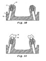
- the position of the implant analog 17 in the hole 16 is unique and perfectly determined. It is then fixed in the hole 16 by for example by a suitable adhesive of polymerizable resin type without contraction which is introduced into the hole 16 by the back of the model 1. It is then possible to remove the analog holder (see figure 10 ).
- the model is ready for the realization of the final prosthesis, for example bars, crowns, or bridges, as is currently done after impression of the jaw of the patient with implants, impression made several weeks after the implant placement.
- a prosthesis in position on the model is illustrated on the figure 11 wherein an abutment member 25 has been attached to each implant analog with overlying the corresponding permanent artificial tooth 26.
- the surgical guide 11 provided with its guide cylinders 9 is placed in the mouth of the patient.
- an implant similar to the implant analog is then introduced using an implant holder similar to the analog holder, that is to say provided with a stop means. in the form of a flange, for example in the form of a flange, and a reference means, for example in the form of a downward projection capable of cooperating with the notch 10 of the guide cylinders 9.
- the implant is thus depressed to the required depth in the proper orientation and its head of identical section to that of the implant analog rotates in the same position that the head 24 of the implant analog on which the prosthesis has been shaped.
- the position of the implants in the mouth is unique and corresponds perfectly to that of the implant analogs in the model, as well as to that appearing on the radiological images in two and three dimensions. We can immediately place the prosthesis that was manufactured before implant placement.
- An advantage of this technique is also that thanks to prosthetic anticipation the exact relative positions of the implants / prosthesis / bone are known and that all depth, rotation and lateral position safeties are determined and fixed. Thus all human errors by drilling are excluded.
Landscapes
- Health & Medical Sciences (AREA)
- Oral & Maxillofacial Surgery (AREA)
- General Health & Medical Sciences (AREA)
- Epidemiology (AREA)
- Life Sciences & Earth Sciences (AREA)
- Animal Behavior & Ethology (AREA)
- Dentistry (AREA)
- Public Health (AREA)
- Veterinary Medicine (AREA)
- Orthopedic Medicine & Surgery (AREA)
- Dental Prosthetics (AREA)
- Dental Tools And Instruments Or Auxiliary Dental Instruments (AREA)
- Prostheses (AREA)
- Apparatus For Radiation Diagnosis (AREA)
Applications Claiming Priority (2)
| Application Number | Priority Date | Filing Date | Title |
|---|---|---|---|
| BE2005/0061A BE1016374A3 (fr) | 2005-02-03 | 2005-02-03 | Procede de fabrication d'une prothese dentaire et appareillage mis en oeuvre. |
| PCT/EP2006/050584 WO2006082198A1 (fr) | 2005-02-03 | 2006-02-01 | Procede de fabrication d ' une prothese dentaire et appareillage mis en oeuvre |
Publications (2)
| Publication Number | Publication Date |
|---|---|
| EP1848366A1 EP1848366A1 (fr) | 2007-10-31 |
| EP1848366B1 true EP1848366B1 (fr) | 2009-04-15 |
Family
ID=34981718
Family Applications (1)
| Application Number | Title | Priority Date | Filing Date |
|---|---|---|---|
| EP06707948A Expired - Lifetime EP1848366B1 (fr) | 2005-02-03 | 2006-02-01 | Procede de fabrication d'une prothese dentaire et appareillage mis en oeuvre |
Country Status (16)
| Country | Link |
|---|---|
| US (1) | US7731497B2 (pt) |
| EP (1) | EP1848366B1 (pt) |
| JP (1) | JP2008528220A (pt) |
| KR (1) | KR20070107105A (pt) |
| CN (1) | CN101111204B (pt) |
| AT (1) | ATE428369T1 (pt) |
| AU (1) | AU2006210244B2 (pt) |
| BE (1) | BE1016374A3 (pt) |
| BR (1) | BRPI0607102A2 (pt) |
| CA (1) | CA2596002A1 (pt) |
| DE (1) | DE602006006290D1 (pt) |
| ES (1) | ES2325333T3 (pt) |
| IL (1) | IL184870A (pt) |
| RU (1) | RU2007132916A (pt) |
| WO (1) | WO2006082198A1 (pt) |
| ZA (1) | ZA200707516B (pt) |
Cited By (1)
| Publication number | Priority date | Publication date | Assignee | Title |
|---|---|---|---|---|
| US9993312B2 (en) | 2013-08-30 | 2018-06-12 | Zfx Gmbh | Intraoral reference body |
Families Citing this family (46)
| Publication number | Priority date | Publication date | Assignee | Title |
|---|---|---|---|---|
| SE522958C2 (sv) | 2000-12-29 | 2004-03-16 | Nobel Biocare Ab | Förfarande, arrangemang (anordning) och program vid eller för protetisk installation |
| EP1906862B1 (en) | 2005-06-30 | 2018-05-23 | Biomet 3i, LLC | Method of creating a dental laboratory model |
| US8257083B2 (en) | 2005-10-24 | 2012-09-04 | Biomet 3I, Llc | Methods for placing an implant analog in a physical model of the patient's mouth |
| US11219511B2 (en) | 2005-10-24 | 2022-01-11 | Biomet 3I, Llc | Methods for placing an implant analog in a physical model of the patient's mouth |
| BRPI0712893B1 (pt) * | 2006-07-11 | 2018-02-06 | 2Ingis S.A. | Processo de fabricação de uma prótese óssea ou de uma simulação de pré-implante e aparelhagem para essa fabricação |
| CN101578076B (zh) | 2007-01-10 | 2013-10-23 | 诺贝尔生物服务公司 | 用于牙设计和制备的方法和系统 |
| US8206153B2 (en) | 2007-05-18 | 2012-06-26 | Biomet 3I, Inc. | Method for selecting implant components |
| WO2008147570A1 (en) * | 2007-05-25 | 2008-12-04 | Trevor Bavar | Surgical drill guide and index system |
| US8465282B2 (en) | 2007-05-29 | 2013-06-18 | Immediate Implant Technologies, Llc | Oral implant placement system and method |
| US20090104582A1 (en) * | 2007-10-22 | 2009-04-23 | Gary Allan Duncan | Male threaded implant drill |
| KR20100075448A (ko) * | 2007-08-24 | 2010-07-02 | 2잉기스 에스.에이. | 치과 보철 및 관련 수술 가이드 제조방법 |
| EP2060240A3 (en) | 2007-11-16 | 2009-08-12 | Biomet 3i, LLC | Components for use with a surgical guide for dental implant placement |
| CN101467890B (zh) * | 2007-12-27 | 2012-10-31 | 杨炳德 | 加速牙科诊断及手术规划的系统及观察立体影像的方法 |
| DE102008006048A1 (de) * | 2008-01-25 | 2009-07-30 | Straumann Holding Ag | Verfahren zum Modellieren eines individuellen Zahnersatzes |
| ES2683119T3 (es) | 2008-04-15 | 2018-09-25 | Biomet 3I, Llc | Método de creación de un modelo dental digital preciso de huesos y tejidos blandos |
| EP3000430B1 (en) | 2008-04-16 | 2017-11-15 | Biomet 3i, LLC | Method of virtually developing a surgical guide for dental implant |
| US8509932B2 (en) * | 2008-07-17 | 2013-08-13 | Cadent Ltd. | Methods, systems and accessories useful for procedures relating to dental implants |
| WO2010058358A2 (en) * | 2008-11-21 | 2010-05-27 | Nitilock Ltd | Superelastic washer |
| US8231386B2 (en) * | 2008-12-19 | 2012-07-31 | Paul Hertz | Tooth-implant method and appliance |
| EP2254068B1 (en) | 2009-05-18 | 2020-08-19 | Nobel Biocare Services AG | Method and system providing improved data matching for virtual planning |
| US8899984B2 (en) * | 2009-05-20 | 2014-12-02 | Daniel R. Llop | CT-based, side-loading surgical and laboratory dental implant guide system and method |
| JP5698452B2 (ja) * | 2009-10-14 | 2015-04-08 | 株式会社東芝 | X線ct装置、インプラント施術の支援装置及びインプラント施術の支援プログラム |
| AU2010361200C1 (en) * | 2010-09-21 | 2015-04-16 | Implantdent Co., Ltd. | "Gauge body and method for preparing surgical guide" |
| TWI448276B (zh) * | 2010-11-26 | 2014-08-11 | Po Kun Cheng | 牙齒定位模板及其製造方法 |
| TWI629050B (zh) * | 2010-11-26 | 2018-07-11 | 鄭伯堃 | 用於牙齒定位模板之組件 |
| ES2477288T3 (es) | 2010-12-07 | 2014-07-16 | Biomet 3I, Llc | Elemento de exploración universal para su uso en un implante dental y en análogos de implante dental |
| AU2012255865B8 (en) | 2011-05-16 | 2015-06-04 | Biomet 3I, Llc | Temporary abutment with combination of scanning features and provisionalization features |
| ITTO20110894A1 (it) * | 2011-10-06 | 2013-04-07 | Mario Grillo | Metodo per posizionare analoghi di impianti dentali in un modello, e dima radiologica per attuare tale metodo |
| KR20140119696A (ko) * | 2012-01-06 | 2014-10-10 | 트로피 | 기계가공된 외과용 가이드 |
| US9089382B2 (en) | 2012-01-23 | 2015-07-28 | Biomet 3I, Llc | Method and apparatus for recording spatial gingival soft tissue relationship to implant placement within alveolar bone for immediate-implant placement |
| US9452032B2 (en) | 2012-01-23 | 2016-09-27 | Biomet 3I, Llc | Soft tissue preservation temporary (shell) immediate-implant abutment with biological active surface |
| RU2519630C2 (ru) * | 2012-08-23 | 2014-06-20 | Государственное бюджетное образовательное учреждение высшего профессионального образования "Самарский государственный медицинский университет" Министерства здравоохранения Российской Федерации (ГБОУ ВПО СамГМУ Минздрава России) | Способ дентальной имплантации (варианты) |
| US20140080092A1 (en) | 2012-09-14 | 2014-03-20 | Biomet 3I, Llc | Temporary dental prosthesis for use in developing final dental prosthesis |
| US8905757B2 (en) | 2012-12-03 | 2014-12-09 | E. Kats Enterprises Ltd. | Method and apparatus for measuring a location and orientation of a plurality of implants |
| US8926328B2 (en) | 2012-12-27 | 2015-01-06 | Biomet 3I, Llc | Jigs for placing dental implant analogs in models and methods of doing the same |
| EP2964128A1 (en) * | 2013-03-08 | 2016-01-13 | Trophy | Partial surgical guide |
| RU2544804C1 (ru) * | 2013-12-11 | 2015-03-20 | Государственное бюджетное образовательное учреждение высшего профессионального образования "Самарский государственный медицинский университет" Министерства здравоохранения Российской Федерации | Способ дентальной имплантации (варианты) |
| EP3094283A4 (en) | 2013-12-20 | 2018-01-24 | Biomet 3i, LLC | Dental system for developing custom prostheses through scanning of coded members |
| CN104000665B (zh) * | 2014-05-27 | 2017-09-12 | 中国人民解放军第四军医大学 | 一种立体定位装置 |
| US9700390B2 (en) | 2014-08-22 | 2017-07-11 | Biomet 3I, Llc | Soft-tissue preservation arrangement and method |
| EP3267936A4 (en) | 2015-03-09 | 2018-12-26 | Stephen J. Chu | Gingival ovate pontic and methods of using the same |
| EP3090700A1 (en) * | 2015-05-08 | 2016-11-09 | Vrije Universiteit van Amsterdam | Customized dental implant and associated tooling |
| RU2624164C2 (ru) * | 2015-12-24 | 2017-06-30 | Александр Владимирович Колсанов | Способ дентальной имплантации |
| EP3843656B1 (en) * | 2018-08-29 | 2022-09-07 | Universidade do Porto | Dental prosthesis system, for the use with at least two dental implants |
| EA037711B1 (ru) * | 2019-09-09 | 2021-05-13 | Анастасия Викторовна Филиппова | Индивидуальный шаблон для выполнения остеотомии челюсти и установки дентальных имплантатов с немедленной нагрузкой |
| US11273016B2 (en) * | 2019-11-29 | 2022-03-15 | Dio Corporation | Method of manufacturing digital overdenture and holder abutment mounting guide and fixing bar bending apparatus for holder device applied thereto |
Family Cites Families (13)
| Publication number | Priority date | Publication date | Assignee | Title |
|---|---|---|---|---|
| US6814575B2 (en) * | 1997-02-26 | 2004-11-09 | Technique D'usinage Sinlab Inc. | Manufacturing a dental implant drill guide and a dental implant superstructure |
| US5967777A (en) * | 1997-11-24 | 1999-10-19 | Klein; Michael | Surgical template assembly and method for drilling and installing dental implants |
| US6514258B1 (en) * | 1998-11-04 | 2003-02-04 | Implant Innovations, Inc. | Penetration limiting stop elements for a drill bit used for bone tissue |
| FR2808669B1 (fr) * | 2000-05-11 | 2003-01-24 | Louis Nahmani | Procede, systeme et guide de reperage pour pose d'implant dentaire |
| US6672870B2 (en) * | 2001-03-20 | 2004-01-06 | John G. Knapp | Method and instrumentation for attaching dentures |
| US7574025B2 (en) * | 2002-01-16 | 2009-08-11 | I-Dent Imaging, Inc. | Oral implant template |
| JP2003245289A (ja) * | 2002-02-22 | 2003-09-02 | Univ Nihon | 歯科用インプラント施術支援装置 |
| US6869282B2 (en) * | 2002-03-04 | 2005-03-22 | Robert P. Carmichael | Implant positioning device and method |
| JP3820390B2 (ja) | 2002-08-26 | 2006-09-13 | 株式会社アイキャット | 人工歯根埋入位置算出方法、人工歯根埋入位置算出装置、コンピュータプログラム及び記録媒体 |
| US8038440B2 (en) * | 2003-02-28 | 2011-10-18 | Materialise Dental N.V. | Method for placing and manufacturing a dental superstructure, method for placing implants and accessories used thereby |
| DE10353913C5 (de) * | 2003-11-18 | 2009-03-12 | Straelen, Frank van, Dr. | Verfahren zum Herstellen einer navigierten Bohrschablone für die Einbringung von Zahnimplantatbohrungen |
| BRPI0712893B1 (pt) | 2006-07-11 | 2018-02-06 | 2Ingis S.A. | Processo de fabricação de uma prótese óssea ou de uma simulação de pré-implante e aparelhagem para essa fabricação |
| KR20100075448A (ko) | 2007-08-24 | 2010-07-02 | 2잉기스 에스.에이. | 치과 보철 및 관련 수술 가이드 제조방법 |
-
2005
- 2005-02-03 BE BE2005/0061A patent/BE1016374A3/fr not_active IP Right Cessation
-
2006
- 2006-02-01 CA CA002596002A patent/CA2596002A1/fr not_active Abandoned
- 2006-02-01 US US11/815,115 patent/US7731497B2/en not_active Expired - Fee Related
- 2006-02-01 KR KR1020077020188A patent/KR20070107105A/ko not_active Ceased
- 2006-02-01 AT AT06707948T patent/ATE428369T1/de not_active IP Right Cessation
- 2006-02-01 AU AU2006210244A patent/AU2006210244B2/en not_active Ceased
- 2006-02-01 BR BRPI0607102-3A patent/BRPI0607102A2/pt not_active IP Right Cessation
- 2006-02-01 ZA ZA200707516A patent/ZA200707516B/xx unknown
- 2006-02-01 EP EP06707948A patent/EP1848366B1/fr not_active Expired - Lifetime
- 2006-02-01 WO PCT/EP2006/050584 patent/WO2006082198A1/fr not_active Ceased
- 2006-02-01 CN CN2006800038318A patent/CN101111204B/zh not_active Expired - Fee Related
- 2006-02-01 DE DE602006006290T patent/DE602006006290D1/de not_active Expired - Lifetime
- 2006-02-01 RU RU2007132916/14A patent/RU2007132916A/ru not_active Application Discontinuation
- 2006-02-01 JP JP2007553600A patent/JP2008528220A/ja active Pending
- 2006-02-01 ES ES06707948T patent/ES2325333T3/es not_active Expired - Lifetime
-
2007
- 2007-07-26 IL IL184870A patent/IL184870A/en not_active IP Right Cessation
Cited By (1)
| Publication number | Priority date | Publication date | Assignee | Title |
|---|---|---|---|---|
| US9993312B2 (en) | 2013-08-30 | 2018-06-12 | Zfx Gmbh | Intraoral reference body |
Also Published As
| Publication number | Publication date |
|---|---|
| ES2325333T3 (es) | 2009-09-01 |
| AU2006210244A1 (en) | 2006-08-10 |
| CA2596002A1 (fr) | 2006-08-10 |
| JP2008528220A (ja) | 2008-07-31 |
| BE1016374A3 (fr) | 2006-09-05 |
| US20080153060A1 (en) | 2008-06-26 |
| ATE428369T1 (de) | 2009-05-15 |
| WO2006082198A1 (fr) | 2006-08-10 |
| WO2006082198A9 (fr) | 2006-11-16 |
| RU2007132916A (ru) | 2009-03-10 |
| AU2006210244B2 (en) | 2011-07-21 |
| EP1848366A1 (fr) | 2007-10-31 |
| IL184870A0 (en) | 2007-12-03 |
| ZA200707516B (en) | 2009-03-25 |
| CN101111204A (zh) | 2008-01-23 |
| DE602006006290D1 (de) | 2009-05-28 |
| US7731497B2 (en) | 2010-06-08 |
| IL184870A (en) | 2010-11-30 |
| BRPI0607102A2 (pt) | 2010-03-09 |
| CN101111204B (zh) | 2010-12-22 |
| KR20070107105A (ko) | 2007-11-06 |
Similar Documents
| Publication | Publication Date | Title |
|---|---|---|
| EP1848366B1 (fr) | Procede de fabrication d'une prothese dentaire et appareillage mis en oeuvre | |
| EP2037834B1 (fr) | Procédé de fabrication d'une prothèse osseuse ou d'une simulation preimplantaire et appareillage mis en oeuvre | |
| EP2192873A1 (fr) | Procédé de fabrication d'une prothèse dentaire et d'un guide chirurgical y afférant | |
| EP1753365B1 (fr) | Guide chirurgical implantaire sur mesure et fraise associée et leur procédé de fabrication | |
| EP1478298B1 (fr) | Procede et dispositif pour la mise en place d'implants dentaires | |
| FR2916626A1 (fr) | Procede de realisation d'un dispositif d'assistance au forage d'au moins un puits d'implantation dans une structure osseuse et dispositif obtenu | |
| CA2422778A1 (fr) | Jeu d'implants et implants correspondants | |
| KR200476682Y1 (ko) | 치아 임플란트용 가이드 스탠트 | |
| US20070141531A1 (en) | Method and marker element to determine the position of a dental implant | |
| WO1991007140A1 (fr) | Implant dentaire, outillage et procede de mise en place | |
| FR2825614A1 (fr) | Methode d'elaboration d'une armature montee sur implants adaptee pour supporter une prothese dentaire | |
| EP2149345A1 (fr) | Dispositif de positionnement d'un axe de référence en vue de la détermination d'un axe de perçage pour la mise en place d'au moins un implant dentaire | |
| FR2942953A1 (fr) | Dispositif prefabrique de positionnement d'un moyen de guidage du percage en implantologie dentaire | |
| WO2019180673A1 (fr) | Dispositif d'assistance au forage d'un puits pour implant dentaire | |
| FR2808669A1 (fr) | Procede, systeme et guide de reperage pour pose d'implant dentaire | |
| EP1622537A2 (fr) | Procede et moyens de mis en oeuvre pour la fabrication d'une barre support de dents prothetiques | |
| KR102607246B1 (ko) | 치과용 임플란트 보철물 제조용 스캔 정보 취득 방법 및 치과용 임플란트 보철물 제조용 스캔 정보 취득 시스템 | |
| WO2024236129A1 (en) | Methods and devices for providing a placer for placing an artificial tooth edge on a tooth or multiple teeth undergoing a restoration process |
Legal Events
| Date | Code | Title | Description |
|---|---|---|---|
| PUAI | Public reference made under article 153(3) epc to a published international application that has entered the european phase |
Free format text: ORIGINAL CODE: 0009012 |
|
| 17P | Request for examination filed |
Effective date: 20070827 |
|
| AK | Designated contracting states |
Kind code of ref document: A1 Designated state(s): AT BE BG CH CY CZ DE DK EE ES FI FR GB GR HU IE IS IT LI LT LU LV MC NL PL PT RO SE SI SK TR |
|
| DAX | Request for extension of the european patent (deleted) | ||
| GRAP | Despatch of communication of intention to grant a patent |
Free format text: ORIGINAL CODE: EPIDOSNIGR1 |
|
| GRAS | Grant fee paid |
Free format text: ORIGINAL CODE: EPIDOSNIGR3 |
|
| GRAA | (expected) grant |
Free format text: ORIGINAL CODE: 0009210 |
|
| RAP1 | Party data changed (applicant data changed or rights of an application transferred) |
Owner name: 2INGIS S.A. |
|
| RIN1 | Information on inventor provided before grant (corrected) |
Inventor name: DE MOYER, PHILIPPE ALBERT PAUL GHISTAIN |
|
| AK | Designated contracting states |
Kind code of ref document: B1 Designated state(s): AT BE BG CH CY CZ DE DK EE ES FI FR GB GR HU IE IS IT LI LT LU LV MC NL PL PT RO SE SI SK TR |
|
| REG | Reference to a national code |
Ref country code: CH Ref legal event code: EP Ref country code: GB Ref legal event code: FG4D Free format text: NOT ENGLISH |
|
| REG | Reference to a national code |
Ref country code: IE Ref legal event code: FG4D |
|
| REF | Corresponds to: |
Ref document number: 602006006290 Country of ref document: DE Date of ref document: 20090528 Kind code of ref document: P |
|
| REG | Reference to a national code |
Ref country code: CH Ref legal event code: NV Representative=s name: SUSI PRYDE-HAENI BSC |
|
| REG | Reference to a national code |
Ref country code: SE Ref legal event code: TRGR |
|
| REG | Reference to a national code |
Ref country code: ES Ref legal event code: FG2A Ref document number: 2325333 Country of ref document: ES Kind code of ref document: T3 |
|
| PG25 | Lapsed in a contracting state [announced via postgrant information from national office to epo] |
Ref country code: LT Free format text: LAPSE BECAUSE OF FAILURE TO SUBMIT A TRANSLATION OF THE DESCRIPTION OR TO PAY THE FEE WITHIN THE PRESCRIBED TIME-LIMIT Effective date: 20090415 Ref country code: PT Free format text: LAPSE BECAUSE OF FAILURE TO SUBMIT A TRANSLATION OF THE DESCRIPTION OR TO PAY THE FEE WITHIN THE PRESCRIBED TIME-LIMIT Effective date: 20090915 Ref country code: AT Free format text: LAPSE BECAUSE OF FAILURE TO SUBMIT A TRANSLATION OF THE DESCRIPTION OR TO PAY THE FEE WITHIN THE PRESCRIBED TIME-LIMIT Effective date: 20090415 Ref country code: FI Free format text: LAPSE BECAUSE OF FAILURE TO SUBMIT A TRANSLATION OF THE DESCRIPTION OR TO PAY THE FEE WITHIN THE PRESCRIBED TIME-LIMIT Effective date: 20090415 |
|
| PG25 | Lapsed in a contracting state [announced via postgrant information from national office to epo] |
Ref country code: LV Free format text: LAPSE BECAUSE OF FAILURE TO SUBMIT A TRANSLATION OF THE DESCRIPTION OR TO PAY THE FEE WITHIN THE PRESCRIBED TIME-LIMIT Effective date: 20090415 Ref country code: IS Free format text: LAPSE BECAUSE OF FAILURE TO SUBMIT A TRANSLATION OF THE DESCRIPTION OR TO PAY THE FEE WITHIN THE PRESCRIBED TIME-LIMIT Effective date: 20090815 Ref country code: SI Free format text: LAPSE BECAUSE OF FAILURE TO SUBMIT A TRANSLATION OF THE DESCRIPTION OR TO PAY THE FEE WITHIN THE PRESCRIBED TIME-LIMIT Effective date: 20090415 Ref country code: PL Free format text: LAPSE BECAUSE OF FAILURE TO SUBMIT A TRANSLATION OF THE DESCRIPTION OR TO PAY THE FEE WITHIN THE PRESCRIBED TIME-LIMIT Effective date: 20090415 |
|
| REG | Reference to a national code |
Ref country code: IE Ref legal event code: FD4D |
|
| PG25 | Lapsed in a contracting state [announced via postgrant information from national office to epo] |
Ref country code: RO Free format text: LAPSE BECAUSE OF FAILURE TO SUBMIT A TRANSLATION OF THE DESCRIPTION OR TO PAY THE FEE WITHIN THE PRESCRIBED TIME-LIMIT Effective date: 20090415 Ref country code: CZ Free format text: LAPSE BECAUSE OF FAILURE TO SUBMIT A TRANSLATION OF THE DESCRIPTION OR TO PAY THE FEE WITHIN THE PRESCRIBED TIME-LIMIT Effective date: 20090415 Ref country code: EE Free format text: LAPSE BECAUSE OF FAILURE TO SUBMIT A TRANSLATION OF THE DESCRIPTION OR TO PAY THE FEE WITHIN THE PRESCRIBED TIME-LIMIT Effective date: 20090415 Ref country code: DK Free format text: LAPSE BECAUSE OF FAILURE TO SUBMIT A TRANSLATION OF THE DESCRIPTION OR TO PAY THE FEE WITHIN THE PRESCRIBED TIME-LIMIT Effective date: 20090415 Ref country code: IE Free format text: LAPSE BECAUSE OF FAILURE TO SUBMIT A TRANSLATION OF THE DESCRIPTION OR TO PAY THE FEE WITHIN THE PRESCRIBED TIME-LIMIT Effective date: 20090415 |
|
| PLBE | No opposition filed within time limit |
Free format text: ORIGINAL CODE: 0009261 |
|
| STAA | Information on the status of an ep patent application or granted ep patent |
Free format text: STATUS: NO OPPOSITION FILED WITHIN TIME LIMIT |
|
| PG25 | Lapsed in a contracting state [announced via postgrant information from national office to epo] |
Ref country code: SK Free format text: LAPSE BECAUSE OF FAILURE TO SUBMIT A TRANSLATION OF THE DESCRIPTION OR TO PAY THE FEE WITHIN THE PRESCRIBED TIME-LIMIT Effective date: 20090415 |
|
| 26N | No opposition filed |
Effective date: 20100118 |
|
| PG25 | Lapsed in a contracting state [announced via postgrant information from national office to epo] |
Ref country code: BG Free format text: LAPSE BECAUSE OF FAILURE TO SUBMIT A TRANSLATION OF THE DESCRIPTION OR TO PAY THE FEE WITHIN THE PRESCRIBED TIME-LIMIT Effective date: 20090715 |
|
| PG25 | Lapsed in a contracting state [announced via postgrant information from national office to epo] |
Ref country code: GR Free format text: LAPSE BECAUSE OF FAILURE TO SUBMIT A TRANSLATION OF THE DESCRIPTION OR TO PAY THE FEE WITHIN THE PRESCRIBED TIME-LIMIT Effective date: 20090716 Ref country code: MC Free format text: LAPSE BECAUSE OF NON-PAYMENT OF DUE FEES Effective date: 20100301 |
|
| PGFP | Annual fee paid to national office [announced via postgrant information from national office to epo] |
Ref country code: CH Payment date: 20110125 Year of fee payment: 6 Ref country code: SE Payment date: 20110125 Year of fee payment: 6 |
|
| PGFP | Annual fee paid to national office [announced via postgrant information from national office to epo] |
Ref country code: GB Payment date: 20110330 Year of fee payment: 6 |
|
| PGFP | Annual fee paid to national office [announced via postgrant information from national office to epo] |
Ref country code: IT Payment date: 20120228 Year of fee payment: 7 |
|
| PG25 | Lapsed in a contracting state [announced via postgrant information from national office to epo] |
Ref country code: CY Free format text: LAPSE BECAUSE OF FAILURE TO SUBMIT A TRANSLATION OF THE DESCRIPTION OR TO PAY THE FEE WITHIN THE PRESCRIBED TIME-LIMIT Effective date: 20090415 |
|
| PG25 | Lapsed in a contracting state [announced via postgrant information from national office to epo] |
Ref country code: HU Free format text: LAPSE BECAUSE OF FAILURE TO SUBMIT A TRANSLATION OF THE DESCRIPTION OR TO PAY THE FEE WITHIN THE PRESCRIBED TIME-LIMIT Effective date: 20091016 Ref country code: LU Free format text: LAPSE BECAUSE OF NON-PAYMENT OF DUE FEES Effective date: 20100201 |
|
| REG | Reference to a national code |
Ref country code: CH Ref legal event code: PL |
|
| GBPC | Gb: european patent ceased through non-payment of renewal fee |
Effective date: 20120201 |
|
| PG25 | Lapsed in a contracting state [announced via postgrant information from national office to epo] |
Ref country code: TR Free format text: LAPSE BECAUSE OF FAILURE TO SUBMIT A TRANSLATION OF THE DESCRIPTION OR TO PAY THE FEE WITHIN THE PRESCRIBED TIME-LIMIT Effective date: 20090415 Ref country code: CH Free format text: LAPSE BECAUSE OF NON-PAYMENT OF DUE FEES Effective date: 20120229 Ref country code: LI Free format text: LAPSE BECAUSE OF NON-PAYMENT OF DUE FEES Effective date: 20120229 Ref country code: SE Free format text: LAPSE BECAUSE OF NON-PAYMENT OF DUE FEES Effective date: 20120202 |
|
| PG25 | Lapsed in a contracting state [announced via postgrant information from national office to epo] |
Ref country code: GB Free format text: LAPSE BECAUSE OF NON-PAYMENT OF DUE FEES Effective date: 20120201 |
|
| PGFP | Annual fee paid to national office [announced via postgrant information from national office to epo] |
Ref country code: ES Payment date: 20130320 Year of fee payment: 8 |
|
| PGFP | Annual fee paid to national office [announced via postgrant information from national office to epo] |
Ref country code: NL Payment date: 20130222 Year of fee payment: 8 |
|
| REG | Reference to a national code |
Ref country code: NL Ref legal event code: V1 Effective date: 20140901 |
|
| PG25 | Lapsed in a contracting state [announced via postgrant information from national office to epo] |
Ref country code: NL Free format text: LAPSE BECAUSE OF NON-PAYMENT OF DUE FEES Effective date: 20140901 |
|
| REG | Reference to a national code |
Ref country code: ES Ref legal event code: FD2A Effective date: 20150730 |
|
| PG25 | Lapsed in a contracting state [announced via postgrant information from national office to epo] |
Ref country code: ES Free format text: LAPSE BECAUSE OF NON-PAYMENT OF DUE FEES Effective date: 20140202 |
|
| REG | Reference to a national code |
Ref country code: FR Ref legal event code: PLFP Year of fee payment: 11 |
|
| PG25 | Lapsed in a contracting state [announced via postgrant information from national office to epo] |
Ref country code: IT Free format text: LAPSE BECAUSE OF NON-PAYMENT OF DUE FEES Effective date: 20140201 |
|
| REG | Reference to a national code |
Ref country code: FR Ref legal event code: PLFP Year of fee payment: 12 |
|
| REG | Reference to a national code |
Ref country code: FR Ref legal event code: PLFP Year of fee payment: 13 |
|
| PGFP | Annual fee paid to national office [announced via postgrant information from national office to epo] |
Ref country code: DE Payment date: 20180219 Year of fee payment: 13 |
|
| PGFP | Annual fee paid to national office [announced via postgrant information from national office to epo] |
Ref country code: FR Payment date: 20180223 Year of fee payment: 13 |
|
| REG | Reference to a national code |
Ref country code: DE Ref legal event code: R119 Ref document number: 602006006290 Country of ref document: DE |
|
| PG25 | Lapsed in a contracting state [announced via postgrant information from national office to epo] |
Ref country code: DE Free format text: LAPSE BECAUSE OF NON-PAYMENT OF DUE FEES Effective date: 20190903 |
|
| PG25 | Lapsed in a contracting state [announced via postgrant information from national office to epo] |
Ref country code: FR Free format text: LAPSE BECAUSE OF NON-PAYMENT OF DUE FEES Effective date: 20190228 |
|
| PGFP | Annual fee paid to national office [announced via postgrant information from national office to epo] |
Ref country code: BE Payment date: 20210225 Year of fee payment: 16 |
|
| REG | Reference to a national code |
Ref country code: BE Ref legal event code: MM Effective date: 20220228 |
|
| PG25 | Lapsed in a contracting state [announced via postgrant information from national office to epo] |
Ref country code: BE Free format text: LAPSE BECAUSE OF NON-PAYMENT OF DUE FEES Effective date: 20220228 |
|
| P01 | Opt-out of the competence of the unified patent court (upc) registered |
Effective date: 20230505 |