EP1847893A2 - Vorrichtung und Verfahren zum Steuern eines Elektromotors - Google Patents
Vorrichtung und Verfahren zum Steuern eines Elektromotors Download PDFInfo
- Publication number
- EP1847893A2 EP1847893A2 EP07007835A EP07007835A EP1847893A2 EP 1847893 A2 EP1847893 A2 EP 1847893A2 EP 07007835 A EP07007835 A EP 07007835A EP 07007835 A EP07007835 A EP 07007835A EP 1847893 A2 EP1847893 A2 EP 1847893A2
- Authority
- EP
- European Patent Office
- Prior art keywords
- electric motor
- section
- threshold
- actual
- temperature
- Prior art date
- Legal status (The legal status is an assumption and is not a legal conclusion. Google has not performed a legal analysis and makes no representation as to the accuracy of the status listed.)
- Withdrawn
Links
Images



Classifications
-
- G—PHYSICS
- G05—CONTROLLING; REGULATING
- G05B—CONTROL OR REGULATING SYSTEMS IN GENERAL; FUNCTIONAL ELEMENTS OF SUCH SYSTEMS; MONITORING OR TESTING ARRANGEMENTS FOR SUCH SYSTEMS OR ELEMENTS
- G05B19/00—Program-control systems
- G05B19/02—Program-control systems electric
- G05B19/18—Numerical control [NC], i.e. automatically operating machines, in particular machine tools, e.g. in a manufacturing environment, so as to execute positioning, movement or co-ordinated operations by means of program data in numerical form
- G05B19/406—Numerical control [NC], i.e. automatically operating machines, in particular machine tools, e.g. in a manufacturing environment, so as to execute positioning, movement or co-ordinated operations by means of program data in numerical form characterised by monitoring or safety
- G05B19/4062—Monitoring servoloop, e.g. overload of servomotor, loss of feedback or reference
Definitions
- the present invention relates to control of an electric motor.
- the present invention relates to a device and a method for controlling an electric motor used as a driving source of a moving part, in an automatic control system for a movable structure such as a robot, a machine tool or the like.
- a movable structure such as a robot, a machine tool or the like, which uses an electric motor as a driving source
- an abnormal load is applied to the electric motor as a result of the collision of a moving part, such as a robot arm, a tool or the like, with an obstacle or the failure of a reduction gear mechanism of the electric motor
- JP-B-2665984 discloses a method for detecting a collision, in which a disturbance estimation observer, for estimating disturbance torque based on the torque command value and the actually measured velocity value of the electric motor, is incorporated into a control system, and when the estimated disturbance torque is not less than a set value, it is determined that an object to be driven by the electric motor (i.e., a moving part of the movable structure) collides with a foreign object.
- JP-B-2749724 JP-B-2749724
- a previously known disturbance torque resulted from friction, gravity, arm interference, etc. is determined on the basis of the measured velocity value of the electric motor; the orientation of the robot arm, etc., and that the collision of the driven object is detected on the basis of a differential disturbance torque obtained by subtracting the known disturbance torque from the estimated disturbance torque.
- the real-time torque variation of the electric motor due to the collision is estimated as the disturbance torque, and therefore, it is possible to quickly and reliably detect a collision.
- a disturbance torque threshold as a reference for the determination of a collision, is set while taking into consideration, e.g., the structural strength of the driven object, it is possible to prevent the driven object from breaking.
- the viscosity of a lubricating oil supplied to the movable areas of the electric motor and the driven object changes, and friction loss between the movable elements thus varies, under the influence of ambient temperature or the temperature of the electric motor, so that estimated disturbance torque may be significantly affected by the variation of friction loss. More specifically, in a low temperature environment, the viscosity of lubricating oil increases and the measured velocity value thus is lowered compared with the torque command value, and therefore, estimated disturbance torque tends to increase.
- the threshold is set relatively higher than a required value for safety, so as to prevent a false detection from being caused under the influence of temperature.
- this practice may result in the deterioration of safety in an automatic control system.
- the threshold is usually set relatively higher than a required value for safety, so as to prevent a false detection due to temperature, which may also result in a deterioration of safety in an automatic control system.
- the present invention provides a device for controlling an electric motor, comprising an operation monitoring section for monitoring the operating state of an electric motor; and an operation control section for controlling an operation of the electric motor in accordance with a monitored result of the operation monitoring section;
- the operation monitoring section comprising a data obtaining section for obtaining operational data of the electric motor; a threshold determining section for selecting and determining an applicable threshold actually comparable with the operational data, from among mutually different first and second thresholds provided for comparison with the operational data, in a manner as to comply with a given condition in connection with a temperature of the electric motor; and an abnormal-operation judging section for comparing the operational data obtained in the data obtaining section with the applicable threshold determined in the threshold determining section, and judging whether an abnormality arises in the operation of the electric motor; the operation control section being configured to control the operation of the electric motor in accordance with a judged result of the abnormal-operation judging section.
- the abnormal-operation judging section of the operation monitoring section compares real-time operational data of the electric motor with the applicable threshold and determines whether there is an abnormality in the operation of the electric motor, so as to immediately detect the occurrence of an abnormal operation. Then, in accordance with the judged result of the abnormal-operation judging section, the operation control section allows, when an abnormal operation is detected, the electric motor to immediately perform an operation as measures to cope with the situation, such as halting or reversing the operation of the electric motor.
- the threshold determining section is configured to select and determine the applicable threshold from among the first and second thresholds based on the condition in connection with the temperature of the electric motor, so that it is possible to take the fact that the viscosity of a lubricating oil changes due to the influence of the temperature of the electric motor into consideration during the operation of the electric motor, and thus to selectively use either one of the thresholds suiting the temperature of the electric motor, in such a manner that, for example, the first threshold is used as the applicable threshold for abnormal operation if the temperature-related condition is not satisfied, while the second threshold is used as the applicable threshold for abnormal operation if the temperature-related condition is satisfied.
- the operation monitoring section may further comprise a temperature detecting section for detecting the actual temperature of the electric motor.
- the threshold determining section may be configured to compare the actual temperature detected in the temperature detecting section with a reference temperature of the electric motor given as the condition to the threshold determining section, determine a lower one of the first and second thresholds as the applicable threshold in a case where the actual temperature is higher than the reference temperature, and determine a higher one of the first and second thresholds as the applicable threshold in a case where the actual temperature is lower than the reference temperature.
- the operation monitoring section may further comprise a time registering section for measuring the actual resting time of the electric motor.
- the threshold determining section may be configured to compare the actual resting time last measured in the time registering section with the reference resting time of the electric motor given as the condition to the threshold determining section, and determine a lower one of the first and second thresholds as the applicable threshold in a case where the actual resting time is shorter than the reference resting time.
- the time registering section may also be configured to further measure the actual operating time of the electric motor.
- the threshold determining section may be configured to compare the actual operating time last measured in the time registering section with a reference operating time of the electric motor given as the condition in a case where the actual resting time is longer than the reference resting time, determine a lower one of the first and second thresholds as the applicable threshold in a case where the actual operating time is longer than the reference operating time, and determine the a higher one of the first and second thresholds as the applicable threshold in a case where the actual operating time is shorter than the reference operating time.
- the threshold determining section may be configured to select and determine the applicable threshold from among three or more mutually different thresholds provided for comparison with the operational data, so as to comply with the condition.
- the operational data obtained in the data obtaining section may be selected from a group including position deviation, velocity deviation, driving current and estimated disturbance torque, obtained during the operation of the electric motor.
- the present invention further provides a method for monitoring the operating state of an electric motor and controlling the operation of the electric motor in accordance with the operating state as monitored, characterized in that the method comprises the steps of obtaining operational data of the electric motor; providing mutually different first and second thresholds for comparison with the operational data; setting a condition in connection with a temperature of the electric motor, the condition being used for selecting an applicable threshold actually comparable with the operational data, from among the first and second thresholds; selecting and determining the applicable threshold from among the first and second thresholds in a manner as to comply with the condition; comparing the operational data with the applicable threshold and judging whether an abnormality arises in the operation of the electric motor; and controlling the operation of the electric motor in accordance with a judged result relating to an abnormal operation of the electric motor.
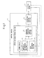
- Fig. 1 shows, by a functional block diagram, a basic configuration of a control device 10 for controlling an electric motor, according to the present invention.
- the control device 10 is typically provided in an automatic control system for a movable structure such as a robot, a machine-tool or the like (not shown), and is configured to control an electric motor 12 used as a driving source of a moving part such as a robot arm, a tool or the like.
- the control device 10 can be functionally incorporated into a controller, such as a robot controller, a numerical control (NC) apparatus or the like, which is previously provided for the movable structure using the electric motor 12 as the driving source of the moving part.
- NC numerical control
- the control device 10 includes an operation monitoring section 14 for monitoring the operating state of the electric motor 12, and an operation control section 16 for controlling the operation of the electric motor 12 in accordance with a monitored result of the operation monitoring section 14.
- the operation monitoring section 14 includes a data obtaining section 18 for obtaining operational data D of the electric motor 12; a threshold determining section 20 for selecting and determining an applicable threshold TA actually comparable with the operational data D, from among mutually different first and second thresholds T1 and T2 provided for comparison with the operational data D, in a manner so as to comply with a given condition C in connection with a temperature of the electric motor 12; and an abnormal-operation judging section 22 for comparing the operational data D obtained in the data obtaining section 18 with the applicable threshold TA determined in the threshold determining section 20, and judging whether an abnormality arises in the operation of the electric motor 12.
- the operation control section 16 is configured to control the operation of the electric motor 12 in accordance with a judged result of the abnormal-operation judging section 22.
- the abnormal-operation judging section 22 of the operation monitoring section 14 compares the real-time operational data D of the electric motor 12 with the applicable threshold TA and determines whether there is an abnormality in the operation of the electric motor 12, so as to immediately detect or determine the cause of the abnormal operation, such as a collision of the moving part, failure of the reduction gear mechanism, etc.
- the operation control section 16 can allow, when the cause of the abnormal operation is detected, the electric motor 12 to immediately perform an operation as a measure to cope with the situation, such as halting or reversing the operation of the electric motor 12.
- the operation control section 16 can allow, when the cause of the abnormal operation is detected, the electric motor 12 to immediately perform an operation as a measure to cope with the situation, such as halting or reversing the operation of the electric motor 12.
- the threshold determining section 20 is configured to select and determine the applicable threshold TA from among the first and second thresholds T1 and T2 (for example, T1 ⁇ T2) in a manner complying with the condition C in connection with the temperature of the electric motor 12, so that it is possible to take the fact that the viscosity of a lubricating oil changes due to the influence of the temperature of the electric motor 12 into consideration during the operation of the electric motor 12, and thus to selectively use either one of the thresholds to suit the temperature of the electric motor 12, in such a manner that, for example the first threshold T1 is used as the applicable threshold TA for the abnormal operation judgment if the temperature-related condition C is not satisfied, while the second threshold T2 is used as the applicable threshold TA for the abnormal operation judgment if the temperature-related condition C is satisfied.
- the condition C in connection with the temperature of the electric motor 12 involves ambient temperature, taking into consideration the fact that the temperature of the electric motor 12 is affected by ambient temperature.
- a threshold having a lower value e.g., T1
- an abnormal-operation judgment criteria can thus be made to be more strict
- a threshold having a higher value e.g., T2
- control device 10 it is possible to quickly and accurately detect the abnormal operation of the electric motor 12 as a result of a collision of the driven object, the failure of the reduction gear mechanism or the like, without being affected by ambient temperature or the temperature of the electric motor (in particular, without causing a false detection due to the increased viscosity of the lubricating oil), and to allow certain measures to cope with the situation, such as halting or reversing the electric motor 12, taken immediately, so as to ensure safety in an automatic control system.
- the first and second thresholds T1 and T2 may be provided by, e.g., manually inputting them into the control device 10 by an operator, or storing them in a storage medium so as to be readable by the control device 10.
- the temperature-related condition C may be given to the control device 10 by inputting by an operator or a reading from a storage medium in a way similar to the above.
- the control device 10 may include an input section and a storage section (not shown) for the thresholds T1, T2 and the condition C.
- the threshold determining section 20 may be configured to select and determine the applicable threshold TA from among three or more mutually different thresholds provided for comparison with the operational data D, in a manner so as to comply with the condition C.
- several kinds or levels of temperature-related conditions C are set (e.g., the temperature-related conditions C are respectively set for the different temperatures of the electric motor 12) so as to suitably and selectively use the three or more thresholds.
- the temperature-related conditions C are respectively set for the different temperatures of the electric motor 12
- the threshold TA optimal for the divided situations can be determined, so that it is possible to accurately detect the abnormal operation of the electric motor 12.
- any of the three or more thresholds correspond to the first and second thresholds T1 and T2, and therefore, the configuration of the control device 10 described above (and the embodiments described later) can be applied to the configuration in which three or more thresholds are provided.
- the operational data D obtained in the data obtaining section 18 may be any one, or desired combination, of position deviation data in a feedback control, velocity deviation data in a feedback control, actually measured driving-current data, and estimated disturbance torque, obtained during the operation of the electric motor 12.
- the position deviation data, the velocity deviation data and the driving current data are obtainable as data commonly used in the feedback control of the electric motor 12.
- the estimated disturbance torque may be one which is estimated from a torque command value and an actually measured velocity value of the electric motor 12, and a disturbance estimating observer for performing such estimation may be incorporated into the data obtaining section 18.
- the position and velocity deviation data may be obtained on the basis of not only a feedback variable from an output element (such as a shaft) of the electric motor 12, but also a feedback variable from a position/velocity detector additionally provided for a driven object (such as a robot arm) of the electric motor 12.
- a feedback variable from an output element such as a shaft
- a position/velocity detector additionally provided for a driven object (such as a robot arm) of the electric motor 12.
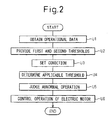
- Fig. 2 shows, by a flow chart, a method for controlling an electric motor, according to the present invention.
- this control method can be embodied by only the control device 10 described above, it may include manual operation by an operator in any of several steps.
- components corresponding to those shown in Fig. 1 are designated by like reference numerals, and the detailed descriptions thereof are not repeated hereafter.
- the control method has a configuration for monitoring the operating state of the electric motor 12, and controlling the operation of the electric motor 12 in accordance with the monitored operating state.
- the operational data D of the electric motor 12 is obtained.
- the first and second thresholds T1 and T2 differing from each other are provided for comparison with the operational data D.
- the condition C in connection with the temperature of the electric motor 12 is set to be used for selecting the applicable threshold TA actually comparable with the operational data D, from among the first and second thresholds T1 and T2.
- the applicable threshold TA is selected and determined from among the first and second thresholds T1 and T2 in a manner as to comply with the condition C.
- step U5 the operational data D is compared with the applicable threshold TA to judge whether an abnormality arises in the operation of the electric motor 12.
- step U6 the operation of the electric motor 12 is controlled in accordance with the judged result in step U5, relating to the abnormal operation of the electric motor 12.
- control method configured as described above can also cause the characteristic effects similar to those of the control device 10 described above.
- three or more thresholds, differing from each other, may be provided for comparison with the operational data D, so as to allow several applicable thresholds TA to be selected and determined from among three or more thresholds, in a manner so as to comply with several kinds or levels of conditions C.
- Fig. 3 shows, by a functional block diagram, a configuration of a control device 30 according to a first preferred embodiment of the present invention.
- the control device 30 has, in addition to the basic configuration of the control device 10 of Fig. 1, a specific configuration in association with the determination of the applicable threshold TA. Therefore, components corresponding to those of the control device 10 are designated by like reference numerals, and the detailed descriptions thereof are not repeated hereafter.
- the operation monitoring section 14 further includes a temperature detecting section 32 for detecting the actual temperature PA of the electric motor 12.
- the threshold determining section 20 is configured to compare the actual temperature PA detected by the temperature detecting section 32 with a reference temperature P0 of the electric motor 12, which is given as the temperature-related condition C to the threshold determining section 20.
- the threshold determining section 20 thus determines a lower one of the first and second thresholds T1 and T2 (e.g., T1) as the applicable threshold TA in a case where the actual temperature PA is higher than the reference temperature P0, and determines a higher one of the first and second thresholds T1 and T2 (e.g., T2) as the applicable threshold TA in a case where the actual temperature PA is lower than the reference temperature P0.
- control device 30 configured as described above, it is possible to selectively use either one of the first and second thresholds T1 and T2 (e.g., T1 ⁇ T2), taking into consideration the situation of the actual temperature PA of the electric motor 12 detected by the temperature detecting section 32 when it is compared with the reference temperature P0 of the electric motor 12 given as the condition C.
- T1 ⁇ T2 e.g., T1 ⁇ T2
- a threshold having a lower value e.g., T1
- an abnormal-operation judgment criteria can thus be made to be more strict
- a threshold having a higher value e.g., T2
- control device 30 it is possible to predict the change in the viscosity of the lubricating oil supplied to the movable areas of the electric motor 12 and the driven object, directly based on the actual temperature PA of the electric motor 12, and thus use the optimal applicable threshold TA for the abnormal operation judgment, so as to further improve the detection accuracy of the abnormal operation of the electric motor 12.
- the reference temperature P0 of the electric motor 12, given as the condition C may be set at a suitable value on the basis of the experiment and experience, taking into consideration an attribute such as the material of the lubricating oil actually supplied to the movable areas of the electric motor 12 and the driven object.
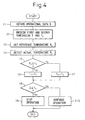
- Fig. 4 shows, by a flow chart, a method for controlling an electric motor, according to the first embodiment of the present invention.
- This control method has a more specific configuration of steps U3 to U6 in the control method of Fig. 2.
- this control method can be embodied by only the control device 30 described above, it may include manual operation by an operator in any of several steps.
- components corresponding to those shown in Fig. 3 are designated by like reference numerals, and the detailed descriptions thereof are not repeated hereafter.
- the operational data D of the electric motor 12 is obtained, and in step V2, the first and second thresholds T1 and T2 differing from each other are provided for comparison with the operational data D (in this embodiment, it is assumed that T1 ⁇ T2).
- the reference temperature P0 of the electric motor 12 is set as the condition C for selecting the applicable threshold TA actually comparable with the operational data D from among the first and second thresholds T1 and T2.
- the actual temperature PA of the electric motor 12 is detected.
- the actual temperature PA is compared with the reference temperature P0.
- the first threshold T1 having the lower value is determined, in step V6, as the applicable threshold TA.
- the second threshold T2 having the higher value is determined, in step V7, as the applicable threshold TA.
- the operational data D is compared with the applicable threshold TA determined in steps V6 and V7. If the operational data D is higher than (and equal to, in the drawing) the applicable threshold TA, it is determined that there is an abnormality in the operation of the electric motor 12, and in step V9, the operation of the electric motor 12 is stopped. On the other hand, if the operational data D is lower than the applicable threshold TA, it is determined that the operation of the electric motor 12 is normal, and in step V10, the electric motor 12 is kept continuous.
- the control method configured as described above can also cause characteristic effects similar to those of the control device 30 described above.
- Fig. 5 shows, by a functional block diagram, a configuration of a control device 40 according to a second preferred embodiment of the present invention.
- the control device 40 has, in addition to the basic configuration of the control device 10 of Fig. 1, a further specific configuration in association with the determination of the applicable threshold TA. Therefore, components corresponding to those of the control device 10 are designated by like reference numerals, and the detailed description thereof is not repeated hereafter.
- the operation monitoring section 14 further comprises a time registering section 42 for measuring the actual resting time RA of the electric motor 12.
- the threshold determining section 20 is configured to compare the actual resting time RA last measured in the time registering section 42 with a reference resting time R0 of the electric motor 12 given as the temperature-related condition C to the threshold determining section 20.
- the threshold determining section 20 thus determines a lower one of the first and second thresholds T1 and T2 (e.g., T1) as the applicable threshold TA in a case where the actual resting time RA is shorter than the reference resting time R0.
- a threshold having a lower value e.g., T1
- T1 a threshold having a lower value
- the electric motor 12 is not affected by residual heat resulting from operation before the present resting time.
- a next operation may have started before the time of measuring, and therefore, it is advantageous to determine the threshold while considering the latest situation of the operation.
- the time registering section 42 is configured to further measure an actual operating time QA of the electric motor 12.
- the threshold determining section 20 compares the actual operating time QA last measured in the time registering section 42 with a reference operating time Q0 of the electric motor 12 given as the temperature-related condition C.
- the threshold determining section 20 thus determines a lower one of the first and second thresholds T1 and T2 (e.g., T1) as the applicable threshold TA in a case where the actual operating time QA is longer than the reference operating time Q0, and determines a higher one of the first and second thresholds T1 and T2 (e.g., T2) as the applicable threshold TA in a case where the actual operating time QA is shorter than the reference operating time Q0.
- the last-measured actual resting time RA of the electric motor 12 is longer than the reference resting time R0, it is possible to selectively use either one of the first and second thresholds T1 and T2 (e.g., T1 ⁇ T2), taking into consideration the situation of the actual operating time QA of the electric motor 12 last measured by the time registering section 42 (i.e., in a current period including a measuring time point) when compared with the reference operating time Q0 of the electric motor 12 given as the condition C.
- the first and second thresholds T1 and T2 e.g., T1 ⁇ T2
- a threshold having a lower value e.g., T1
- an abnormal-operation judgment criteria can thus be made to be more strict.
- a threshold having a higher value e.g., T2
- an abnormal-operation judgment criteria can thus be made to be less strict.
- control device 40 it is possible to predict the change in the viscosity of the lubricating oil supplied to the movable areas of the electric motor 12 and the driven object, indirectly based on the actual resting time RA and the actual operating time QA of the electric motor 12, and thus to use the optimal applicable threshold TA for the abnormal operation judgment, so as to further improve the detection accuracy of the abnormal operation of the electric motor 12.
- the control device 40 may have somewhat less reliable than the above-described control device 30 in which the change in the viscosity of the lubricating oil is directly predicted based on the actual temperature PA of the electric motor 12.
- control device 40 has an advantage that it does not need to provide an additional component such as a temperature sensor as the temperature detecting section 32, but can use a clock typically provided in a control device as the time registering section 42, and thus can be manufactured at a lower cost than the control device 30.
- each of the reference resting time R0 and the reference operating time Q0 of the electric motor 12, given as the condition C, may also be set at a suitable time on the basis of the experiment and experience, taking into consideration an attribute such as the material of the lubricating oil supplied to the movable areas of the electric motor 12 and the driven object.
- Fig. 6 shows, by a flow chart, a method for controlling an electric motor, according to the second embodiment of the present invention.
- This control method has a more specific configuration of steps U3 to U6 in the control method of Fig. 2.
- this control method can be embodied by only the control device 40 described above, it may include manual operation by an operator in any of several steps.
- components corresponding to those shown in Fig. 5 are designated by like reference numerals, and the detailed descriptions thereof are not repeated hereafter.
- step W1 the operational data D of the electric motor 12 is obtained, and in step W2, the first and second thresholds T1 and T2 differing from each other are provided for comparison with the operational data D (in this embodiment, it is assumed that T1 ⁇ T2).
- step W3 the reference resting time R0 of the electric motor 12 is set as the condition C for selecting the applicable threshold TA actually comparable with the operational data D from among the first and second thresholds T1 and T2, and in step W4, the reference operating time Q0 of the electric motor 12 is set.
- step W5 the actual resting time RA of the electric motor 12 is measured, and in step W6, the actual operating time QA of the electric motor 12 is measured.
- the last-measured actual resting time RA is compared with the reference resting time R0. If the last-measured actual resting time RA is shorter than the reference resting time R0, the first threshold T1 having the lower value is determined, in step W8, as the applicable threshold TA. On the other hand, if the last-measured actual resting time RA is longer than (and equal to, in the drawing) the reference resting time R0, the last-measured actual operating time QA is compared, in step W9, with the reference operating time Q0.
- the first threshold T1 having the lower value is determined, in step W8, as the applicable threshold TA.
- the second threshold T2 having the higher value is determined, in step W10, as the applicable threshold TA.
- the operational data D is compared with the applicable threshold TA determined in steps W8 and W10. If the operational data D is higher than (and equal to, in the drawing) the applicable threshold TA, it is determined that there is an abnormality in the operation of the electric motor 12, and in step W12, the operation of the electric motor 12 is stopped. On the other hand, if the operational data D is lower than the applicable threshold TA, it is determined that the operation of the electric motor 12 is normal, and in step W13, the electric motor 12 is kept continuous.
- the control method configured as described above can also cause the characteristic effects similar to those of the control device 40 described above.
Landscapes
- Engineering & Computer Science (AREA)
- Human Computer Interaction (AREA)
- Manufacturing & Machinery (AREA)
- Physics & Mathematics (AREA)
- General Physics & Mathematics (AREA)
- Automation & Control Theory (AREA)
- Control Of Electric Motors In General (AREA)
- Testing And Monitoring For Control Systems (AREA)
Applications Claiming Priority (1)
| Application Number | Priority Date | Filing Date | Title |
|---|---|---|---|
| JP2006113728A JP2007286904A (ja) | 2006-04-17 | 2006-04-17 | 電動機の制御装置及び制御方法 |
Publications (1)
| Publication Number | Publication Date |
|---|---|
| EP1847893A2 true EP1847893A2 (de) | 2007-10-24 |
Family
ID=38017126
Family Applications (1)
| Application Number | Title | Priority Date | Filing Date |
|---|---|---|---|
| EP07007835A Withdrawn EP1847893A2 (de) | 2006-04-17 | 2007-04-17 | Vorrichtung und Verfahren zum Steuern eines Elektromotors |
Country Status (4)
| Country | Link |
|---|---|
| US (1) | US20070244609A1 (de) |
| EP (1) | EP1847893A2 (de) |
| JP (1) | JP2007286904A (de) |
| CN (1) | CN101059697A (de) |
Cited By (1)
| Publication number | Priority date | Publication date | Assignee | Title |
|---|---|---|---|---|
| EP2913163B1 (de) * | 2012-10-25 | 2019-10-09 | Panasonic Intellectual Property Management Co., Ltd. | Anzeigeverfahren für roboterfehlfunktion |
Families Citing this family (32)
| Publication number | Priority date | Publication date | Assignee | Title |
|---|---|---|---|---|
| JP5130091B2 (ja) | 2008-03-25 | 2013-01-30 | Juki株式会社 | 布切り装置 |
| JP2009240379A (ja) | 2008-03-28 | 2009-10-22 | Juki Corp | ボタン穴かがり縫いミシン |
| CN101727092B (zh) * | 2008-10-31 | 2012-06-20 | 鸿富锦精密工业(深圳)有限公司 | 频谱分析系统及方法 |
| KR101474765B1 (ko) * | 2008-12-05 | 2014-12-22 | 삼성전자 주식회사 | 로봇 팔 및 그 제어방법 |
| ITMI20111868A1 (it) * | 2011-10-13 | 2013-04-14 | Gima Spa | Procedimento per il controllo dell'interferenza e/o collisione d'organi meccanici e sistema connesso |
| US8587246B2 (en) * | 2012-04-17 | 2013-11-19 | GM Global Technology Operations LLC | System and method for estimating electrical current in motor control circuits to improve performance and diagnostic capability |
| US9081649B2 (en) * | 2012-10-29 | 2015-07-14 | Honda Motor Co., Ltd. | Vehicle including movable partition and controller |
| FR3002048B1 (fr) * | 2013-02-14 | 2016-07-01 | Commissariat Energie Atomique | Procede de detection amelioree de collision d'un robot avec son environnement, systeme et produit programme d'ordinateur mettant en œuvre le procede |
| EP2816364B1 (de) * | 2013-06-20 | 2023-09-27 | Abb Ag | Wiederholungstestanordnung und Wiederholungstestverfahren für eine Schaltanlage |
| JP6320540B2 (ja) * | 2014-09-04 | 2018-05-09 | 三菱電機株式会社 | 異常検出装置及び異常検出方法 |
| JP5863919B1 (ja) | 2014-09-30 | 2016-02-17 | ファナック株式会社 | 工作機械の制御装置 |
| CN105879384A (zh) * | 2014-11-03 | 2016-08-24 | 韦琳 | 一种麻将机电机机构故障提前预警方法 |
| CN104699078B (zh) * | 2015-02-27 | 2017-07-28 | 北京精密机电控制设备研究所 | 机电伺服系统保护与故障恢复控制方法 |
| JP6572062B2 (ja) * | 2015-08-26 | 2019-09-04 | 日立建機株式会社 | 診断装置 |
| EP3351356B1 (de) | 2015-09-16 | 2020-11-18 | Panasonic Intellectual Property Management Co., Ltd. | Verfahren zur erkennung von roboterkollisionen |
| CN105717917B (zh) * | 2016-04-25 | 2018-03-02 | 上汽大众汽车有限公司 | 新能源汽车驱动电机台架的自动标定方法 |
| DE112017002846T5 (de) * | 2016-06-07 | 2019-02-28 | Mitsubishi Electric Corporation | Vorrichtung zur Abnormalitätsdiagnose und Verfahren zur Abnormalitätsdiagnose |
| JP6157772B1 (ja) * | 2016-06-16 | 2017-07-05 | 三菱電機株式会社 | サーボ制御診断システム |
| JP6953690B2 (ja) * | 2016-08-10 | 2021-10-27 | 株式会社ジェイテクト | 解析システム |
| US11300949B2 (en) | 2017-08-11 | 2022-04-12 | Jtekt Corporation | Data processing device of production equipment |
| JP7035368B2 (ja) * | 2017-08-11 | 2022-03-15 | 株式会社ジェイテクト | 生産設備の解析装置 |
| JP6939298B2 (ja) * | 2017-09-13 | 2021-09-22 | 中国電力株式会社 | 監視装置及び監視システム |
| CN108058188B (zh) * | 2017-11-24 | 2021-04-30 | 苏州灵猴机器人有限公司 | 机器人健康监测和故障诊断系统的控制方法 |
| EP3733361B1 (de) * | 2017-12-26 | 2023-08-23 | Nissan Motor Co., Ltd. | Verfahren zur bestimmung einer fehlfunktion und vorrichtung zur bestimmung einer fehlfunktion |
| MX2020008692A (es) * | 2018-02-28 | 2020-09-25 | Nissan Motor | Dispositivo de deteccion de anormalidad y metodo de deteccion de anormalidad. |
| JP7105646B2 (ja) | 2018-08-02 | 2022-07-25 | 株式会社神戸製鋼所 | ロボット制御装置、ロボット制御方法及びプログラム |
| JP7192458B2 (ja) * | 2018-12-07 | 2022-12-20 | オムロン株式会社 | 情報処理装置、情報処理方法および情報処理プログラム |
| JP7088056B2 (ja) * | 2019-02-04 | 2022-06-21 | 株式会社デンソー | 粒子状物質検出センサ |
| JP7454419B2 (ja) * | 2020-03-25 | 2024-03-22 | 三菱重工業株式会社 | プラント運転データ監視装置及び方法 |
| JPWO2022071106A1 (de) * | 2020-09-30 | 2022-04-07 | ||
| CN117980837A (zh) * | 2021-09-24 | 2024-05-03 | 利乐拉瓦尔集团及财务有限公司 | 用于移动机器部件的状态监测的方法 |
| JP2025040807A (ja) * | 2023-09-12 | 2025-03-25 | 株式会社東芝 | 異常検知装置、方法及びプログラム |
Family Cites Families (4)
| Publication number | Priority date | Publication date | Assignee | Title |
|---|---|---|---|---|
| US5373205A (en) * | 1992-12-29 | 1994-12-13 | Cincinnati Milacron Inc. | Method and apparatus for limiting motor current |
| US5436784A (en) * | 1993-08-11 | 1995-07-25 | Schweitzer Engineering Laboratories, Inc. | Motor protection relay using thermal models |
| FR2759504B1 (fr) * | 1997-02-10 | 1999-03-26 | Schneider Electric Sa | Relais et procede de protection |
| JP4391719B2 (ja) * | 2002-03-20 | 2009-12-24 | トヨタ自動車株式会社 | モータ温度推定装置およびモータ制御装置 |
-
2006
- 2006-04-17 JP JP2006113728A patent/JP2007286904A/ja active Pending
-
2007
- 2007-04-16 CN CNA2007100963841A patent/CN101059697A/zh active Pending
- 2007-04-16 US US11/735,986 patent/US20070244609A1/en not_active Abandoned
- 2007-04-17 EP EP07007835A patent/EP1847893A2/de not_active Withdrawn
Cited By (1)
| Publication number | Priority date | Publication date | Assignee | Title |
|---|---|---|---|---|
| EP2913163B1 (de) * | 2012-10-25 | 2019-10-09 | Panasonic Intellectual Property Management Co., Ltd. | Anzeigeverfahren für roboterfehlfunktion |
Also Published As
| Publication number | Publication date |
|---|---|
| US20070244609A1 (en) | 2007-10-18 |
| CN101059697A (zh) | 2007-10-24 |
| JP2007286904A (ja) | 2007-11-01 |
Similar Documents
| Publication | Publication Date | Title |
|---|---|---|
| EP1847893A2 (de) | Vorrichtung und Verfahren zum Steuern eines Elektromotors | |
| CN101162394B (zh) | 异常诊断方法及其装置 | |
| US10081088B2 (en) | Main spindle failure detection device for machine tool and method of detecting main spindle failure | |
| CN101823663B (zh) | 电梯门控制装置 | |
| KR101626458B1 (ko) | 공작기계의 공구이상 검출장치 | |
| US20140156057A1 (en) | Machine tool including numerical controller with function to determine replacement time for maintenance component | |
| EP3299132A1 (de) | Fehlerdiagnosevorrichtung und fehlerdiagnoseverfahren | |
| KR20200076712A (ko) | 기계 장치의 열화 진단 장치, 열화 진단 장치에서 실행되는 기계 장치의 열화 진단 방법, 및 기계 장치의 열화 진단 방법 | |
| US20130275016A1 (en) | Automatic transmission control apparatus | |
| JP2016002634A (ja) | 工作機械の熱変位補正装置 | |
| JP2006281421A (ja) | ロボットおよびロボットの異常検出方法 | |
| TWI452822B (zh) | 馬達控制裝置 | |
| EP3499327B1 (de) | Lastzustandsdiagnosevorrichtung und lastzustandsdiagnoseverfahren für servomotor | |
| US10946523B2 (en) | Failure diagnostic device and failure diagnostic method | |
| US7800332B2 (en) | Motor drive system and method for predicting position during power interruption | |
| US20160259320A1 (en) | Numerical controller capable of avoiding overheat of spindle | |
| US20060247888A1 (en) | Machine tool | |
| CN112276937B (zh) | 故障预测系统 | |
| KR20210082670A (ko) | 전력 소모 모니터링 시스템 및 이의 방법 | |
| KR20170118834A (ko) | 승강기의 작업 상황 감시 장치 및 작업 상황 감시 방법 | |
| US9753456B2 (en) | Device for detecting decrease in rotational speed of cooling fan of machine tool | |
| US20170090468A1 (en) | Method and system for error detection and monitoring for an electronically closed-loop or open-loop controlled machine part | |
| KR101973870B1 (ko) | 차량의 제어장치 및 제어방법 | |
| US20050073398A1 (en) | Warning algorithms for vehicle driveline failures | |
| EP1804359B1 (de) | Motorsteuerungsvorrichtung und Motorsteuerungsverfahren |
Legal Events
| Date | Code | Title | Description |
|---|---|---|---|
| PUAI | Public reference made under article 153(3) epc to a published international application that has entered the european phase |
Free format text: ORIGINAL CODE: 0009012 |
|
| AK | Designated contracting states |
Kind code of ref document: A2 Designated state(s): AT BE BG CH CY CZ DE DK EE ES FI FR GB GR HU IE IS IT LI LT LU LV MC MT NL PL PT RO SE SI SK TR |
|
| AX | Request for extension of the european patent |
Extension state: AL BA HR MK YU |
|
| STAA | Information on the status of an ep patent application or granted ep patent |
Free format text: STATUS: THE APPLICATION HAS BEEN WITHDRAWN |
|
| 18W | Application withdrawn |
Effective date: 20080128 |