EP1847672A2 - Joint assembly for actuating a flap, in particular a smoke exhaust flap - Google Patents
Joint assembly for actuating a flap, in particular a smoke exhaust flap Download PDFInfo
- Publication number
- EP1847672A2 EP1847672A2 EP07005998A EP07005998A EP1847672A2 EP 1847672 A2 EP1847672 A2 EP 1847672A2 EP 07005998 A EP07005998 A EP 07005998A EP 07005998 A EP07005998 A EP 07005998A EP 1847672 A2 EP1847672 A2 EP 1847672A2
- Authority
- EP
- European Patent Office
- Prior art keywords
- linear drive
- drive element
- flap
- pivot axis
- tension spring
- Prior art date
- Legal status (The legal status is an assumption and is not a legal conclusion. Google has not performed a legal analysis and makes no representation as to the accuracy of the status listed.)
- Granted
Links
Images

Classifications
-
- E—FIXED CONSTRUCTIONS
- E04—BUILDING
- E04D—ROOF COVERINGS; SKY-LIGHTS; GUTTERS; ROOF-WORKING TOOLS
- E04D13/00—Special arrangements or devices in connection with roof coverings; Protection against birds; Roof drainage; Sky-lights
- E04D13/03—Sky-lights; Domes; Ventilating sky-lights
- E04D13/035—Sky-lights; Domes; Ventilating sky-lights characterised by having movable parts
- E04D13/0351—Sky-lights; Domes; Ventilating sky-lights characterised by having movable parts the parts pivoting about a fixed axis
- E04D13/0355—The parts being of vaulted shape
-
- E—FIXED CONSTRUCTIONS
- E05—LOCKS; KEYS; WINDOW OR DOOR FITTINGS; SAFES
- E05F—DEVICES FOR MOVING WINGS INTO OPEN OR CLOSED POSITION; CHECKS FOR WINGS; WING FITTINGS NOT OTHERWISE PROVIDED FOR, CONCERNED WITH THE FUNCTIONING OF THE WING
- E05F15/00—Power-operated mechanisms for wings
- E05F15/50—Power-operated mechanisms for wings using fluid-pressure actuators
- E05F15/53—Power-operated mechanisms for wings using fluid-pressure actuators for swinging wings
-
- E—FIXED CONSTRUCTIONS
- E05—LOCKS; KEYS; WINDOW OR DOOR FITTINGS; SAFES
- E05F—DEVICES FOR MOVING WINGS INTO OPEN OR CLOSED POSITION; CHECKS FOR WINGS; WING FITTINGS NOT OTHERWISE PROVIDED FOR, CONCERNED WITH THE FUNCTIONING OF THE WING
- E05F15/00—Power-operated mechanisms for wings
- E05F15/60—Power-operated mechanisms for wings using electrical actuators
- E05F15/603—Power-operated mechanisms for wings using electrical actuators using rotary electromotors
- E05F15/611—Power-operated mechanisms for wings using electrical actuators using rotary electromotors for swinging wings
- E05F15/63—Power-operated mechanisms for wings using electrical actuators using rotary electromotors for swinging wings operated by swinging arms
-
- E—FIXED CONSTRUCTIONS
- E05—LOCKS; KEYS; WINDOW OR DOOR FITTINGS; SAFES
- E05F—DEVICES FOR MOVING WINGS INTO OPEN OR CLOSED POSITION; CHECKS FOR WINGS; WING FITTINGS NOT OTHERWISE PROVIDED FOR, CONCERNED WITH THE FUNCTIONING OF THE WING
- E05F1/00—Closers or openers for wings, not otherwise provided for in this subclass
- E05F1/002—Closers or openers for wings, not otherwise provided for in this subclass controlled by automatically acting means
- E05F1/006—Closers or openers for wings, not otherwise provided for in this subclass controlled by automatically acting means by emergency conditions, e.g. fire
-
- E—FIXED CONSTRUCTIONS
- E05—LOCKS; KEYS; WINDOW OR DOOR FITTINGS; SAFES
- E05F—DEVICES FOR MOVING WINGS INTO OPEN OR CLOSED POSITION; CHECKS FOR WINGS; WING FITTINGS NOT OTHERWISE PROVIDED FOR, CONCERNED WITH THE FUNCTIONING OF THE WING
- E05F5/00—Braking devices, e.g. checks; Stops; Buffers
- E05F5/06—Buffers or stops limiting opening of swinging wings, e.g. floor or wall stops
- E05F5/08—Buffers or stops limiting opening of swinging wings, e.g. floor or wall stops with springs
-
- E—FIXED CONSTRUCTIONS
- E05—LOCKS; KEYS; WINDOW OR DOOR FITTINGS; SAFES
- E05Y—INDEXING SCHEME RELATING TO HINGES OR OTHER SUSPENSION DEVICES FOR DOORS, WINDOWS OR WINGS AND DEVICES FOR MOVING WINGS INTO OPEN OR CLOSED POSITION, CHECKS FOR WINGS AND WING FITTINGS NOT OTHERWISE PROVIDED FOR, CONCERNED WITH THE FUNCTIONING OF THE WING
- E05Y2201/00—Constructional elements; Accessories therefore
- E05Y2201/40—Motors; Magnets; Springs; Weights; Accessories therefore
- E05Y2201/404—Motors; Magnets; Springs; Weights; Accessories therefore characterised by the function
- E05Y2201/422—Motors; Magnets; Springs; Weights; Accessories therefore characterised by the function for opening
-
- E—FIXED CONSTRUCTIONS
- E05—LOCKS; KEYS; WINDOW OR DOOR FITTINGS; SAFES
- E05Y—INDEXING SCHEME RELATING TO HINGES OR OTHER SUSPENSION DEVICES FOR DOORS, WINDOWS OR WINGS AND DEVICES FOR MOVING WINGS INTO OPEN OR CLOSED POSITION, CHECKS FOR WINGS AND WING FITTINGS NOT OTHERWISE PROVIDED FOR, CONCERNED WITH THE FUNCTIONING OF THE WING
- E05Y2201/00—Constructional elements; Accessories therefore
- E05Y2201/40—Motors; Magnets; Springs; Weights; Accessories therefore
- E05Y2201/43—Motors
- E05Y2201/434—Electromotors; Details thereof
-
- E—FIXED CONSTRUCTIONS
- E05—LOCKS; KEYS; WINDOW OR DOOR FITTINGS; SAFES
- E05Y—INDEXING SCHEME RELATING TO HINGES OR OTHER SUSPENSION DEVICES FOR DOORS, WINDOWS OR WINGS AND DEVICES FOR MOVING WINGS INTO OPEN OR CLOSED POSITION, CHECKS FOR WINGS AND WING FITTINGS NOT OTHERWISE PROVIDED FOR, CONCERNED WITH THE FUNCTIONING OF THE WING
- E05Y2201/00—Constructional elements; Accessories therefore
- E05Y2201/40—Motors; Magnets; Springs; Weights; Accessories therefore
- E05Y2201/47—Springs; Spring tensioners
- E05Y2201/488—Traction springs
-
- E—FIXED CONSTRUCTIONS
- E05—LOCKS; KEYS; WINDOW OR DOOR FITTINGS; SAFES
- E05Y—INDEXING SCHEME RELATING TO HINGES OR OTHER SUSPENSION DEVICES FOR DOORS, WINDOWS OR WINGS AND DEVICES FOR MOVING WINGS INTO OPEN OR CLOSED POSITION, CHECKS FOR WINGS AND WING FITTINGS NOT OTHERWISE PROVIDED FOR, CONCERNED WITH THE FUNCTIONING OF THE WING
- E05Y2900/00—Application of doors, windows, wings or fittings thereof
- E05Y2900/10—Application of doors, windows, wings or fittings thereof for buildings or parts thereof
- E05Y2900/13—Application of doors, windows, wings or fittings thereof for buildings or parts thereof characterised by the type of wing
- E05Y2900/148—Windows
- E05Y2900/152—Roof windows
- E05Y2900/154—Skylights
Definitions
- the invention relates to a joint arrangement for actuating a flap, in particular a smoke outlet flap or dome, according to the preamble of claim 1.
- the linear drive element is arranged centrally under a movable truss part, which is pivotable together with the flue outlet flap.
- the linear drive element in the form of a cylinder essentially serves to actuate a locking of the flue outlet flap at a location remote from the first axis of rotation thereof and for this purpose communicates with the latch via a spindle or rod.
- a second end of the linear drive element is articulated to a movable truss part or its associated flap via a first rod, which can be regarded as a lever.
- a second rod which can be regarded as a support lever, hingedly connected to a lower portion of a fixed essay or Aufsatzkranzes on which is rotatably mounted above the ventilation frame of the flue outlet flap.
- Two opening mechanisms are symmetrical to the vertical center plane in which the linear drive element is arranged is, at a great distance to this arranged on both parallel inner sides of the curb. They engage with one end approximately in the middle of the longitudinal extent of the sides of the attachment to this.
- Each of the two opening mechanisms comprises a hydropneumatic spring and a tension spring made of metal, which are arranged in mutually parallel vertical planes.
- the attachment point of the attachment opposite end of the hydropneumatic spring is connected to the movable ventilation frame, so that it is approximately horizontal in the closed position of the frame.
- the attachment point opposite end of the metallic tension spring is lowered in contrast in this position of the ventilation frame and is connected via a one-sided articulated linkage with the movable ventilation frame in combination.
- the two opening mechanisms are intended to provide substantially the actuating force for opening the smoke vent, while the central actuator, which comprises an actuating cylinder or linear actuator, is intended to provide the force required for closing and to assist in opening only Overload reliably effect.
- the effect of the opening mechanisms is triggered by the unlocking means of the central drive element.
- This inadequacy also has another hinge arrangement for actuating a flap, in particular flue flap, with only one central linear drive element, in which not only the support lever, but also the lever at a distance to an end portion of the drive element, in which they are pivotally mounted, respectively a stationary axis of rotation or pivot axis are pivotable ( EP 0 971 091 B1 ). Since these axes can be short, reaction forces of the linear drive element become Initially initiated via the reversing lever and the support lever only in fixed pivot points of the reversing lever and the support lever. Traverse parts are therefore not essential.
- the present invention has for its object to provide an uncomplicated, compact hinge assembly, which avoids the disadvantages of the above known hinge assemblies, in particular, the flap and the movable ventilation frame twisting forces are minimized even if to assist the opening and to damp the opening movement is provided in the end position and closing at least one tension spring in addition to the linear drive element.
- the solution according to the invention thus consists in a unique integration of the at least one tension spring in the hinge assembly with the linear drive element, wherein the hinge assembly substantially the pivotable at a lower portion of the linear drive member about a first pivot axis support lever and also hinged to the lower portion additional lever includes, and wherein the support lever is connected to a lower attachment portion of the attachment and the bell crank over it may also be connected to the attachment or instead with the movable flap.
- the hinge assembly according to the characterizing part of claim 1 is characterized in that the second end of the tension spring is connected to a lower portion of the linear drive member which includes the first pivot axis about which the linear drive element is pivotable.
- the first end of the tension spring is firmly connected to a spring connection point with the attachment, which is farther away from the first axis of rotation of the flap than the first pivot axis of the linear drive element.
- the tension spring is the power transmission of the tension spring on the flap and the essay on the same support lever and the same lever, which are provided for the linear drive element. It thus eliminates additional levers for the tension spring.
- This standardization has been found to be functionally useful, although the spring force need not be in the same direction on the support lever and on the bell crank as the force induced by the linear drive member.
- the tension spring with the linear drive element starting the opening system comprising the linear drive element and the tension spring can be further optimized by the vertical plane in which the tension spring is located near the vertical center plane in which the drive element is located.
- the entire opening system is very compact.
- the second end of the tension spring is attached to the first pivot axis of the linear drive element.
- the load of a housing of the drive element is minimized by forces and moments.
- the hinge assembly according to the invention can be used universally, e.g. in conjunction with a flap which has no inserted into a movable ventilation frame, thus also movable truss part and which also in the fixed essay or essay wreath over which the flap is pivotable, no lower, with the essay firmly connected truss part.
- a compact unit for installation in an essay or curb which also includes the tension spring, however, can be advantageously prepared according to claim 3 using a stationary truss part which is mounted in the essay and above which after assembly, the flap is rotated about the first axis of rotation can be.
- the assembly with the stationary cross member and the linear drive element, the tension spring is integrated in the opening system with the Traversen matter. This reduces the on-site assembly work.
- the unit is particularly compact in that the stationary cross member is dimensioned narrower than the attachment in which it is mounted, wherein the tension spring is disposed within the stationary cross member.
- a second, movable truss part can be rotatably connected to the first, stationary truss part about the first axis of rotation, whereby the degree of integration is further increased and the on-site assembly work is minimized.
- the pivotable connection point of the linear drive element remote from the first rotation axis is arranged for the flap on the movable cross member to which the flap is attached.
- the hinge arrangement according to claim 5 has the features that above the stationary truss part a movable together with the flap truss part is rotatable, on which the remote from the first axis of rotation pivotal connection point of the linear drive element is arranged, that the first end of the reversing lever to the first Pivot axis of the linear drive element is pivotable, wherein a second end of the reversing lever is pivotally mounted on the movable truss part at a distance from the first axis of rotation and to the pivotal connection point of the linear drive element.
- the single linear drive element, the flap on the movable truss part can be pivoted beyond a normal opening position 120 ° out into an alarm position in which the opening angle can be 165 °.
- the second end of the tension spring is advantageously attached to the first pivot axis of the linear drive element.
- the second end of the tension spring is in any case arranged as close as possible to the first pivot axis of the linear drive element.
- tension spring in an embodiment of the joint arrangement which is designed so that it does not initiate any additional transverse forces on the flap on which the linear drive element engages, so that a traverse or a truss bottom is not required , which allows a lightweight material-saving design.
- This embodiment is characterized according to claim 6, characterized in that a second end of the reversing lever, whose first end is pivotable about a third pivot axis on the linear drive element, on a fixed pivot point is mounted, such that the first pivot axis of the linear drive element on the support lever and the third pivot axis about which the lever is pivotable on the linear drive element, upon actuation of the linear drive element describe circular trajectories that intersect and a resulting rotation of the cause linear drive element.
- the second end of the tension spring for transmitting power to the support lever and the bellcrank according to claim 7 may be attached to the lower portion of the linear drive member including the first pivot axis on the support lever and the third pivot axis on the bellcrank.
- a reliable, structurally simple attachment of the second end of the tension spring to the linear drive element is achieved according to claim 8 with a bolt-shaped projection which projects laterally from the linear drive element and on which engages the second end of the tension spring.
- the bolt-shaped projection can be designed to be screwed into the linear drive element.
- the bolt-shaped projection extends in extension of the first pivot axis away from the linear drive element, i. the bolt-shaped projection and the first pivot axis are concentric.
- two tension springs on both sides of the linear drive element symmetrically to this and attached thereto.
- the hinge assembly is mounted on a fixed truss member comprising two struts parallel to each other and to the vertical median plane of the linear drive member
- the two tension springs are arranged compactly between the two struts so as to be the vertical plane of the linear strut Include drive element.
- a support in the closed position of the flap between the first end and the second end of the tension spring, so that the tension spring in this position of the flap on the Pad rests and is angled from this to the first pivot axis of the linear drive element, which is located in the closed position of the flap below the second stationary truss part. This ensures that the spring force acts at an angle to the linear drive element, under which the tension spring in the first opening phase of the flap supports the opening particularly effective. This may be necessary or desirable in particular when the flap is frozen.
- the second end of the tension spring can be protected and aesthetically pleasing in the closed position of the flap within the essay, which also includes the linear drive element, the support lever and the lever.
- the joint arrangement according to FIGS. 1-4 or 5 serves to actuate a dome 1, which together with a movable truss part 2 is rotatable about a first axis of rotation (P 0 ).
- the movable truss part 2 is, as Figure 3 shows, mounted centrally in a movable fan frame 4, which in turn carries the dome 1.
- the movable truss part In the closed position of the fan frame 3 shown in Figures 1 and 3, the movable truss part is located on a lower, fixed truss part 4, which comprises two fixedly connected struts 4 ', 4 ", which are arranged symmetrically to the vertical center plane, not shown.
- a support bracket 5 extends vertically downwards from the left-hand side of the stationary truss part 4 in Figures 1 to 4.
- the movable truss part has a less high bracket in this area, which is designated 6 in Figures 1 and 4.
- the linear drive element 7 can be realized as an electric motor or as a pneumatic or hydraulic cylinder.
- the dome can be rotated in a very wide range of rotation, which can extend over approximately 165 °.
- the rod 8 is hinged on the first axis of rotation P 0 opposite side to the movable truss part 2, namely at the pivotal connection point P 1st
- a lower portion of the linear drive element 7 is mounted on a first pivot axis P 2 , which is not stationary, see. Figures 1 and 2, and on which engages one end of a support lever 9, whose opposite end is mounted on a second pivot axis P 3 below in the support bracket 5.
- An additional reversing lever 11 is on the one hand also connected to the first pivot axis P 2 on the linear drive element and on the other hand mounted in a rotation axis P 4 , which is arranged on the bracket 6 of the upper movable truss part 2 near the first axis of rotation P 0 .
- the axis of rotation P 4 is in any case closer to the first axis of rotation P 0 than the center of the upper part of the cross member.
- the first axis of rotation P 0 , the first and second pivot axis P 2 , P 3 and the axis of rotation P 4 form a four-bar or together with the first pivotal joint P 1 a five-bar joint, which said large opening angle in an alarm position of the dome with the single active linear drive element 7 allows.
- a locking device 12 at the end of the rod 8, at the pivotal connection point P 1 can be unlocked by an initial movement of the linear drive member to a pivoting of the upper movable truss part 2 with the dome 1 to allow, but it has no further influence on the dome motion.
- the linear drive element is based on the support lever 10 on the first pivot axis P 2 , which can not dodge down clockwise because of the reversing lever 11. Therefore, with the first pivot axis P 2, the elements connected to it are pivoted in the counterclockwise direction, in particular in the wide open position shown in FIG.
- the initial opening under heavy load of the linear drive element e.g. by snow load or frozen dome to facilitate and on the other hand, the dome in the wide open position not accelerated by the weight of their end position to beat, in the described hinge assembly two tension springs 13, 14 integrated in planes parallel to the vertical center plane and between the upper movable truss part 2 and the struts 4 ', 4 "of the lower stationary truss part 4 are arranged, see in particular Figures 3 and 4.
- each of the tension springs 13, 14 is connected to a spring attachment point 16, 17, which may be realized by a profile piece, each with one of the struts 4 ', 4 "of the stationary truss part 4, see Figures 1, 2 and 3.
- the spring attachment point is farther from the first axis of rotation P 0 than the first pivot axis P 2 on the linear drive element, which can be seen in particular in the closed position of the dome of FIG.
- the respective second end of the tension spring 13 and 14 is attached to the first pivot axis P 2 of the linear drive element, which in the closed position of the flap between the spring mounting point 16 and 17 and the first axis of rotation Po, and the second pivot axis P 3 and the P 4 axis of rotation is located.
- each of the tension springs 13, 14 In order to improve the angle of attack of the second end of each of the tension springs 13, 14 from above on the linear drive element 7 in the closed position of the dome, ie to make it steeper, is on the struts 4 ', 4 "of the stationary truss part 4 depending on a support 18, 19 mounted from a profile piece so that one of the tension springs, approximately in their middle, on the support in the closed position of the dome, whereby each spring, starting from its approximately horizontal portion at the spring mounting point 16 and 17 from the support 18 and 19 is angled downward to the second spring end, which is in communication with the first pivot axis P 2.
- the second end of the tension spring 13 or 14 so sharply engages the lower portion 9 of the linear drive element that the spring is effectively trying lifting or lifting the linear drive member when the latch 12 is released at the start of the flap lift-up
- the springs 13, 14 opening the dome until the first pivot axis P 2 on the linear drive element has reached about the position P ' 2 in Figure 1, ie in the particularly critical initial phase of the opening.
- a particular advantage of the joint arrangement is that the two tension springs 13, 14 act on the same first pivot axis P 2 on the linear drive element 7 as the support lever 10 and the lever 11, so that the tensile forces of the two tension springs 13, 14 without additional levers - Or transmission elements are introduced with great effect in the joint assembly.
- axles of the second embodiment are the same as those of the first embodiment.
- the second embodiment differs from the first embodiment discussed above, inter alia, in that in the second embodiment, no lower stationary truss member and no upper movable truss member are provided. In the second embodiment, no additional transverse forces are introduced to a flap 22 on which a linear drive element 23 acts. Only forces are introduced into the flap 22 at the first axis of rotation P 0 and at the pivotable connection point P 1 of the linear drive element 23 on the flap 22. This also applies to the derived from the tensile force of the tension spring 24 force components.
- a locking element 25 is also provided in the second embodiment at the opposite end to the first axis of rotation P 0 of the flap 22, to which a rod 26 of the linear drive element 23 engages, which is designed here as Doppelhubzylinder.
- the end of the rod 26 is arranged at the pivotable connection point P 1 .
- the locking element cooperates with a console, which is fixedly mounted inside an attachment 28, so that upon actuation of the rod 26 is unlocked.
- a further bracket 29 is fastened to the inside of the attachment and can protrude approximately vertically downwards.
- the additional bracket 29 serves not only for supporting a support lever 30 pivotally mounted on a first pivot axis P 2 of the linear drive element but also for an additional reversing lever 31 on a stationary rotation axis P 4 '.
- the stationary axis of rotation P 4 'of the reversing lever is closer to the stationary first axis of rotation P 0 of the flap than the second stationary pivot axis P 3 of the support lever.
- the second pivot axis P 3 and the fixed axis of rotation P 4 ' may be arranged along a vertical line.
- the reversing lever 31 is articulated about a third movable pivot axis P 5 on the linear drive element 23, in its lower portion 32, which includes the third pivot axis P 5 and the first pivot axis P 2 .
- the first pivot axis P 2 and the third pivot axis P 5 are preferably located in a central axis 23a of the linear drive element 23.
- the tension spring 24 engages a second spring attachment point on the lower portion 32 of the linear drive member 33, between the first pivot axis P 2 of the linear drive member and the third pivot axis P 5 of the linear drive element.
- the spring thus runs with the flap closed, as shown in FIG. 6, below the linear drive element 23.
- the second embodiment according to Figures 6 and 7 is characterized by straightforward structure including the tension spring.
Abstract
Description
Die Erfindung betrifft eine Gelenkanordnung zur Betätigung einer Klappe, insbesondere Rauchabzugsklappe oder Kuppel, nach dem Oberbegriff des Anspruchs 1.The invention relates to a joint arrangement for actuating a flap, in particular a smoke outlet flap or dome, according to the preamble of claim 1.
Bei einer derartigen bekannten Gelenkanordnung zur Betätigung einer Rauchabzugsklappe gemäß
Ansonsten sind vollständig selbsttätig betätigbare Gelenkanordnungen von RWA-Geräten bekannt, welche ein Öffnen und Schließen einer Klappe über einen großen Schwenkbereich mit nur einem linearen Antriebselement bewerkstelligen. Hierzu ist bei einer solchen bekannten Gelenkanordnung mit einem linearen Antriebselement an dessen erster Schwenkachse außer einem Stützhebel ein zusätzlicher Umlenkhebel mit einem ersten Ende schwenkbar angeordnet. Das zweite Ende des Umlenkhebels greift schwenkbar an einem oberen Traversenteil der Klappe im Abstand zu deren Drehachse und zu der Anbringungsstelle des ersten Endes des Antriebselements an (
Diese Unzulänglichkeit hat auch eine andere Gelenkanordnung zur Betätigung einer Klappe, insbesondere Rauchabzugsklappe, mit nur einem zentralen linearen Antriebselement, bei der nicht nur der Stützhebel, sondern auch der Umlenkhebel im Abstand zu einem Endabschnitt des Antriebselements, in dem sie schwenkbar gelagert sind, jeweils um eine ortsfeste Drehachse bzw. Schwenkachse schwenkbar sind (
Der vorliegenden Erfindung liegt die Aufgabe zugrunde, eine unkomplizierte, kompakte Gelenkanordnung zu schaffen, welche Nachteile der obigen bekannten Gelenkanordnungen vermeidet, bei der insbesondere die Klappe und den beweglichen Lüftungsrahmen verwindende Kräfte auch dann minimiert sind, wenn zur Unterstützung des Öffnens sowie zum Dämpfen der Öffnungsbewegung in der Endstellung und beim Schließen wenigstens eine Zugfeder zusätzlich zu dem linearen Antriebselement vorgesehen ist.The present invention has for its object to provide an uncomplicated, compact hinge assembly, which avoids the disadvantages of the above known hinge assemblies, in particular, the flap and the movable ventilation frame twisting forces are minimized even if to assist the opening and to damp the opening movement is provided in the end position and closing at least one tension spring in addition to the linear drive element.
Diese Aufgabe wird für eine Gelenkanordnung mit den in Anspruch 1 angegebenen Merkmalen gelöst.This object is achieved for a joint assembly with the features specified in claim 1.
Die erfindungsgemäße Lösung besteht also in einer einzigartigen Integration der mindestens einen Zugfeder in die Gelenkanordnung mit dem linearen Antriebselement, wobei die Gelenkanordnung im wesentlichen den an einem unteren Abschnitt des linearen Antriebselements um eine erste Schwenkachse schwenkbaren Stützhebel sowie einen ebenfalls an dem unteren Abschnitt angelenkten zusätzlichen Umlenkhebel umfasst, und wobei der Stützhebel mit einem unteren Aufsatzabschnitt des Aufsatzes verbunden ist und der Umlenkhebel darüber ebenfalls mit dem Aufsatz verbunden sein kann oder statt dessen mit der beweglichen Klappe.The solution according to the invention thus consists in a unique integration of the at least one tension spring in the hinge assembly with the linear drive element, wherein the hinge assembly substantially the pivotable at a lower portion of the linear drive member about a first pivot axis support lever and also hinged to the lower portion additional lever includes, and wherein the support lever is connected to a lower attachment portion of the attachment and the bell crank over it may also be connected to the attachment or instead with the movable flap.
Im einzelnen zeichnet sich die Gelenkanordnung gemäß dem kennzeichnenden Teil des Anspruchs 1 dadurch aus, dass das zweite Ende der Zugfeder mit einem unteren Abschnitt des linearen Antriebselements verbunden ist, der die erste Schwenkachse einschließt, um die das lineare Antriebselement schwenkbar ist. Dabei steht das erste Ende der Zugfeder an einer Federverbindungsstelle mit dem Aufsatz fest in Verbindung, die weiter von der ersten Drehachse der Klappe entfernt ist als die erste Schwenkachse des linearen Antriebselements.In particular, the hinge assembly according to the characterizing part of claim 1 is characterized in that the second end of the tension spring is connected to a lower portion of the linear drive member which includes the first pivot axis about which the linear drive element is pivotable. In this case, the first end of the tension spring is firmly connected to a spring connection point with the attachment, which is farther away from the first axis of rotation of the flap than the first pivot axis of the linear drive element.
Bei dieser Anordnung der Zugfeder erfolgt die Kraftübertragung der Zugfeder auf die Klappe und den Aufsatz über den gleichen Stützhebel und den gleichen Umlenkhebel, die für das lineare Antriebselement vorgesehen sind. Es entfallen somit zusätzliche Hebel für die Zugfeder. Diese Vereinheitlichung hat sich als funktionell brauchbar bzw. günstig herausgestellt, obwohl die Federkraft nicht in gleicher Richtung an dem Stützhebel und an dem Umlenkhebel anzugreifen braucht wie die von dem linearen Antriebselement hervorgerufene Kraft.In this arrangement, the tension spring is the power transmission of the tension spring on the flap and the essay on the same support lever and the same lever, which are provided for the linear drive element. It thus eliminates additional levers for the tension spring. This standardization has been found to be functionally useful, although the spring force need not be in the same direction on the support lever and on the bell crank as the force induced by the linear drive member.
Da die Federkraft an den gleichen Stellen in die Klappe bzw. deren Rahmen eingeleitet wird, wie die Kraft des linearen Antriebselements, und da die Krafteinleitung für das lineare Antriebselement und die Zugfeder auch an dem Aufsatz die gleiche ist, werden in die Klappe und den zugehörigen Lüftungsrahmen praktisch keine Verwindungskräfte eingebracht.Since the spring force is introduced into the same places in the flap or its frame, as the force of the linear drive element, and since the application of force for the linear drive element and the tension spring is also the same on the essay, are in the flap and the associated Ventilation frame introduced virtually no torsional forces.
Von dieser Verbindung der Zugfeder mit dem linearen Antriebselement ausgehend kann das Öffnungssystem umfassend das lineare Antriebselement und die Zugfeder weiter optimiert werden, indem die vertikale Ebene, in der die Zugfeder liegt, nahe der vertikalen Mittelebene angeordnet wird, in der das Antriebselement liegt. Damit ist das gesamte Öffnungssystem sehr kompakt ausgebildet.From this connection of the tension spring with the linear drive element starting the opening system comprising the linear drive element and the tension spring can be further optimized by the vertical plane in which the tension spring is located near the vertical center plane in which the drive element is located. Thus, the entire opening system is very compact.
Vorteilhaft ist das zweite Ende der Zugfeder an der ersten Schwenkachse des linearen Antriebselements angebracht. Hierbei ist die Belastung eines Gehäuses des Antriebselements durch Kräfte und Momente minimiert.Advantageously, the second end of the tension spring is attached to the first pivot axis of the linear drive element. Here, the load of a housing of the drive element is minimized by forces and moments.
Die erfindungsgemäße Gelenkanordnung kann universell eingesetzt werden, z.B. in Verbindung mit einer Klappe, die kein in einen beweglichen Lüftungsrahmen eingesetztes, somit ebenfalls bewegliches Traversenteil aufweist und die auch in dem ortsfesten Aufsatz bzw. Aufsatzkranz, über dem die Klappe schwenkbar ist, kein unteres, mit dem Aufsatz fest verbundenes Traversenteil umfasst.The hinge assembly according to the invention can be used universally, e.g. in conjunction with a flap which has no inserted into a movable ventilation frame, thus also movable truss part and which also in the fixed essay or essay wreath over which the flap is pivotable, no lower, with the essay firmly connected truss part.
Eine kompakte Einheit zum Einbau in einen Aufsatz bzw. Aufsatzkranz, die auch die Zugfeder umfasst, kann jedoch gemäß Anspruch 3 vorteilhaft unter Verwendung eines ortsfesten Traversenteils hergestellt sein, welches in dem Aufsatz angebracht wird und über dem nach Montage die Klappe um die erste Drehachse gedreht werden kann. Bei dieser Ausbildung der Baugruppe mit dem ortsfesten Traversenteil und dem linearen Antriebselement ist die Zugfeder in dem Öffnungssystem mit den Traversenteilen integriert. Dadurch verringert sich der bauseitige Montageaufwand.A compact unit for installation in an essay or curb, which also includes the tension spring, however, can be advantageously prepared according to
Die Einheit ist besonders kompakt, indem das ortsfeste Traversenteil schmaler als der Aufsatz bemessen ist, in dem es montiert wird, wobei die Zugfeder innerhalb des ortsfesten Traversenteils angeordnet ist.The unit is particularly compact in that the stationary cross member is dimensioned narrower than the attachment in which it is mounted, wherein the tension spring is disposed within the stationary cross member.
Mit dem ersten, ortsfesten Traversenteil kann weiterhin gemäß Anspruch 5 ein zweites, bewegliches Traversenteil um die erste Drehachse drehbar verbunden sein, womit der Integrationsgrad weiter erhöht und der bauseitige Montageaufwand minimiert wird. In diesem Fall ist die von der ersten Drehachse entfernte schwenkbare Verbindungsstelle des linearen Antriebselements für die Klappe an dem beweglichen Traversenteil angeordnet, an dem die Klappe angebracht wird. Die Gelenkanordnung nach Anspruch 5 weist die Merkmale auf, dass über dem ortsfesten Traversenteil ein zusammen mit der Klappe bewegliches Traversenteil drehbar ist, an dem die von der ersten Drehachse entfernte schwenkbare Verbindungsstelle des linearen Antriebselements angeordnet ist, dass das erste Ende des Umlenkhebels um die erste Schwenkachse des linearen Antriebselements schwenkbar ist, wobei ein zweites Ende des Umlenkhebels schwenkbar an dem beweglichen Traversenteil im Abstand zu deren erster Drehachse und zu der schwenkbaren Verbindungsstelle des linearen Antriebselements angeordnet ist. Bei dieser Gelenkanordnung kann das einzige lineare Antriebselement die Klappe an dem beweglichen Traversenteil über eine normale Öffnungsstellung 120° hinaus in eine Alarmstellung geschwenkt werden, in der der Öffnungswinkel um 165° betragen kann.Furthermore, according to
Wie oben erwähnt ist insbesondere bei der voranstehenden Gelenkanordnung das zweite Ende der Zugfeder vorteilhaft an der ersten Schwenkachse des linearen Antriebselements angebracht. Ansonsten wird das zweite Ende der Zugfeder jedenfalls möglichst nahe an der ersten Schwenkachse des linearen Antriebselements angeordnet.As mentioned above, particularly in the case of the above joint arrangement, the second end of the tension spring is advantageously attached to the first pivot axis of the linear drive element. Otherwise, the second end of the tension spring is in any case arranged as close as possible to the first pivot axis of the linear drive element.
Es ist aber auch möglich, die Zugfeder in eine Ausführungsform der Gelenkanordnung zu integrieren, die so ausgebildet ist, dass diese an der Klappe, an der das lineare Antriebselement angreift, keine zusätzlichen Querkräfte einleitet, so dass eine Traverse bzw. ein Traversenunterteil nicht erforderlich ist, womit eine leichte materialsparende Bauweise ermöglicht wird. Diese Ausführungsform ist gemäß Anspruch 6 dadurch gekennzeichnet, dass ein zweites Ende des Umlenkhebels, dessen erstes Ende um eine dritte Schwenkachse an dem linearen Antriebselement schwenkbar ist, an einem ortsfesten Drehpunkt gelagert ist, dergestalt, dass die erste Schwenkachse des linearen Antriebselements an dem Stützhebel sowie die dritte Schwenkachse, um welche der Umlenkhebel an dem linearen Antriebselement schwenkbar ist, bei Betätigung des linearen Antriebselements kreisförmige Bewegungsbahnen beschreiben, die sich kreuzen und eine resultierende Drehung des linearen Antriebselements hervorrufen.But it is also possible to integrate the tension spring in an embodiment of the joint arrangement which is designed so that it does not initiate any additional transverse forces on the flap on which the linear drive element engages, so that a traverse or a truss bottom is not required , which allows a lightweight material-saving design. This embodiment is characterized according to
Insbesondere bei der letztgenannten Ausführungsform kann das zweite Ende der Zugfeder zur Kraftübertragung auf den Stützhebel und den Umlenkhebel gemäß Anspruch 7 an dem unteren Abschnitt des linearen Antriebselements angebracht sein, der die erste Schwenkachse an dem Stützhebel und die dritte Schwenkachse an dem Umlenkhebel einschließt.Particularly in the latter embodiment, the second end of the tension spring for transmitting power to the support lever and the bellcrank according to claim 7 may be attached to the lower portion of the linear drive member including the first pivot axis on the support lever and the third pivot axis on the bellcrank.
Eine zuverlässige, konstruktiv einfache Anbringung des zweiten Endes der Zugfeder an dem linearen Antriebselement wird gemäß Anspruch 8 mit einem bolzenförmigen Ansatz erreicht, der von dem linearen Antriebselement seitlich absteht und an dem das zweite Ende der Zugfeder angreift. Der bolzenförmige Ansatz kann in das lineare Antriebselement einschraubbar ausgebildet sein.A reliable, structurally simple attachment of the second end of the tension spring to the linear drive element is achieved according to claim 8 with a bolt-shaped projection which projects laterally from the linear drive element and on which engages the second end of the tension spring. The bolt-shaped projection can be designed to be screwed into the linear drive element.
In dem Falle, in dem das zweite Ende der Zugfeder an der ersten Schwenkachse des linearen Antriebselements angebracht werden soll, erstreckt sich der bolzenförmige Ansatz in Verlängerung der ersten Schwenkachse von dem linearen Antriebselement weg, d.h. der bolzenförmige Ansatz und die erste Schwenkachse sind konzentrisch.In the case where the second end of the tension spring is to be attached to the first pivot axis of the linear drive element, the bolt-shaped projection extends in extension of the first pivot axis away from the linear drive element, i. the bolt-shaped projection and the first pivot axis are concentric.
Um die Funktionssicherheit der Gelenkanordnung zu erhöhen und um auf das lineare Antriebselement keine seitliche Kippkraft auszuüben, die versuchen könnte, das Antriebselement aus der vertikalen Ebene herauszuschwenken, sind gemäß Anspruch 10 bevorzugt zwei Zugfedern beidseitig des linearen Antriebselements symmetrisch zu diesem angeordnet und an diesem angebracht.In order to increase the reliability of the hinge assembly and to exert on the linear drive element no lateral tilting force that might try to swing out the drive element from the vertical plane, are preferably arranged according to
In dem Fall, in dem die Gelenkanordnung an einem ortsfesten Traversenteil angebracht ist, welches zwei parallel zueinander und zu der vertikalen Mittelebene des linearen Antriebselements verlaufende Streben umfasst, sind die beiden Zugfedern kompakt zwischen den beiden Streben so angeordnet, dass sie die vertikale Ebene des linearen Antriebselements einschließen.In the case where the hinge assembly is mounted on a fixed truss member comprising two struts parallel to each other and to the vertical median plane of the linear drive member, the two tension springs are arranged compactly between the two struts so as to be the vertical plane of the linear strut Include drive element.
Bei der Ausführungsform der Gelenkanordnung mit einem ortsfesten Traversenteil ist auf diesem besonders vorteilhaft gemäß Anspruch 12 eine Auflage angeordnet, und zwar in geschlossener Stellung der Klappe zwischen dem ersten Ende und dem zweiten Ende der Zugfeder, so dass die Zugfeder in dieser Stellung der Klappe auf der Auflage aufliegt und von dieser zu der ersten Schwenkachse des linearen Antriebselements abgewinkelt ist, die sich in geschlossener Stellung der Klappe unterhalb des zweiten ortsfesten Traversenteils befindet. Damit wird erreicht, dass die Federkraft in einem Winkel an dem linearen Antriebselement angreift, unter dem die Zugfeder in der ersten Öffnungsphase der Klappe das Öffnen besonders wirksam unterstützt. Dies kann insbesondere bei Vereisung der Klappe erforderlich bzw. wünschenswert sein.In the embodiment of the joint assembly with a stationary truss member is arranged on this particularly advantageous according to
Gemäß Anspruch 1 3 kann sich jedenfalls das zweite Ende der Zugfeder geschützt und ästhetisch ansprechend in geschlossener Stellung der Klappe innerhalb des Aufsatzes befinden, der auch das lineare Antriebselement, den Stützhebel und den Umlenkhebel einschließt.In any case, according to claim 1 3, the second end of the tension spring can be protected and aesthetically pleasing in the closed position of the flap within the essay, which also includes the linear drive element, the support lever and the lever.
Die Erfindung wird im folgenden anhand zweiter Ausführungsbeispiele erläutert, die in der Zeichnung mit sieben Figuren dargestellt sind, aus denen sich weitere Konkretisierungen der erfindungsgemäßen Merkmale ergeben können. Es zeigen:
- Figur 1
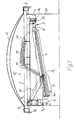
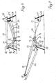
- ein erstes Ausführungsbeispiel einer Gelenkanordnung zur Betätigung einer Kuppel in einer Rauch- und Wärmeabzugsanlage (RWA-Anlage) in geschlossener Stellung der Kuppel in einem Längsschnitt durch eine vertikale Mittelebene der Gelenkanordnung, wobei die Gelenkanordnung an einem ersten oberen beweglichen Traversenteil angreift, das mit der Kuppel in Verbindung steht, sowie an einem unteren ortsfesten Traversenteil angreift, welches in einem Aufsatzkranz befestigt ist,
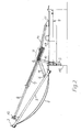
Figur 2- die Gelenkanordnung in der gleichen Ansicht wie in Figur 1, jedoch in voll geöffneter Stellung der Kuppel,
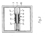
Figur 3- eine Draufsicht auf den Öffnungsbeschlag gemäß den Figuren.1 und 2, der mit dem unteren ortsfesten Traversenteil und dem oberen beweglichen Traversenteil gebildet ist, mit einem Aufsatzkranz, in dem das untere ortsfeste Traversenteil befestigt ist, und einem Lüfterrahmen, der an dem oberen beweglichen Traversenteil angebracht ist,
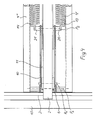
Figur 4- eine detailliertere Draufsicht auf einen Ausschnitt des Öffnungsbeschlags gemäß Figur 3,
Figur 5- eine Draufsicht auf Anbringungsstellen von Zugfedern an dem unteren ortsfesten Traversenteil in einem Ausschnitt,
Figur 6- einen Längsschnitt durch eine zweite Ausführungsform der Gelenkanordnung zur Betätigung einer Klappe, ebenfalls in einem Schnitt in einer vertikalen Mittelebene der Gelenkanordnung bei geschlossener Stellung der Klappe und
- Figur 7
- die zweite Ausführungsform gemäß Figur 6, jedoch in voll geöffneter Stellung der Klappe.
- FIG. 1
- a first embodiment of a hinge assembly for actuating a dome in a smoke and heat exhaust system (RWA system) in the closed position of the dome in a longitudinal section through a vertical median plane of the hinge assembly, wherein the hinge assembly engages a first upper movable truss member, which engages with the dome in contact, as well as acts on a lower stationary truss part, which is mounted in a curb,
- FIG. 2
- the joint arrangement in the same view as in Figure 1, but in the fully open position of the dome,
- FIG. 3
- a plan view of the opening fitting according to Figures 1 and 2, which is formed with the lower stationary truss part and the upper movable truss part, with a curb in which the lower stationary truss part is fixed, and a fan frame, which at the upper movable truss part is appropriate,
- FIG. 4
- a more detailed plan view of a section of the opening fitting of Figure 3,
- FIG. 5
- a plan view of mounting locations of tension springs on the lower stationary truss part in a section,
- FIG. 6
- a longitudinal section through a second embodiment of the hinge assembly for actuating a flap, also in a section in a vertical median plane of the hinge assembly in the closed position of the flap and
- FIG. 7
- the second embodiment according to Figure 6, but in the fully open position of the flap.
Die Gelenkanordnung gemäß den Figuren 1 - 4 bzw. 5 dient zur Betätigung einer Kuppel 1, die zusammen mit einem beweglichen Traversenteil 2 um eine erste Drehachse (P0) drehbar ist. Das bewegliche Traversenteil 2 ist, wie Figur 3 zeigt, zentral in einem beweglichen Lüfterrahmen 4 angebracht, der seinerseits die Kuppel 1 trägt.The joint arrangement according to FIGS. 1-4 or 5 serves to actuate a dome 1, which together with a
In der in den Figuren 1 und 3 dargestellten geschlossenen Stellung des Lüfterrahmens 3 liegt das bewegliche Traversenteil auf einem unteren, ortsfesten Traversenteil 4, welches zwei fest miteinander verbundene Streben 4', 4" umfasst, die symmetrisch zu der nicht dargestellten vertikalen Mittelebene angeordnet sind. Von der in den Figuren 1 - 4 linken Seite des ortsfesten Traversenteils 4 erstreckt sich eine Tragkonsole 5 senkrecht nach unten. Das bewegliche Traversenteil hat in diesem Bereich eine weniger hohe Konsole, die in den Figuren 1 und 4 mit 6 bezeichnet ist.In the closed position of the
Zum Öffnen und Schließen der Kuppel dient nur ein lineares Antriebselement 7, welches eine Stange 8 betätigt. Das lineare Antriebselement kann als elektrischer Motor oder als pneumatischer oder hydraulischer Zylinder realisiert sein. Mit dem einzigen linearen Antriebselement ist in der Ausführungsform gemäß den Figuren 1 - 5 die Kuppel in einem sehr weiten Drehbereich drehbar, der sich über etwa 165° erstrecken kann.To open and close the dome is only a linear drive element 7, which actuates a rod 8. The linear drive element can be realized as an electric motor or as a pneumatic or hydraulic cylinder. With the single linear drive element, in the embodiment according to FIGS. 1-5, the dome can be rotated in a very wide range of rotation, which can extend over approximately 165 °.
Zum Drehen der Kuppel 1 mit dem Lüfterrahmen 3 über das obere bewegliche Traversenteil 2 ist die Stange 8 auf der der ersten Drehachse P0 entgegengesetzten Seite an dem beweglichen Traversenteil 2 angelenkt, und zwar an der schwenkbaren Verbindungsstelle P1.To rotate the dome 1 with the
Ein unterer Abschnitt des linearen Antriebselements 7 ist an einer ersten Schwenkachse P2 gelagert, die nicht ortsfest ist, vgl. Figuren 1 und 2, und an der ein Ende eines Stützhebels 9 angreift, dessen entgegengesetztes Ende an einer zweiten Schwenkachse P3 unten in der Tragkonsole 5 gelagert ist.A lower portion of the linear drive element 7 is mounted on a first pivot axis P 2 , which is not stationary, see. Figures 1 and 2, and on which engages one end of a support lever 9, whose opposite end is mounted on a second pivot axis P 3 below in the
Ein zusätzlicher Umlenkhebel 11 ist einerseits ebenfalls mit der ersten Schwenkachse P2 an dem linearen Antriebselement verbunden und andererseits in einer Drehachse P4 gelagert, die an der Konsole 6 des oberen beweglichen Traversenteils 2 nahe der ersten Drehachse P0 angeordnet ist. Die Drehachse P4 befindet sich jedenfalls näher zur ersten Drehachse P0 als die Mitte des Traversenoberteils.An additional reversing
Die erste Drehachse P0, die erste und die zweite Schwenkachse P2, P3 und die Drehachse P4 bilden ein Viergelenk bzw. zusammen mit der ersten schwenkbaren Verbindungsstelle P1 ein Fünfgelenk, welches den genannten großen Öffnungswinkel in eine Alarmstellung der Kuppel mit dem einzigen aktiven linearen Antriebselement 7 ermöglicht.The first axis of rotation P 0 , the first and second pivot axis P 2 , P 3 and the axis of rotation P 4 form a four-bar or together with the first pivotal joint P 1 a five-bar joint, which said large opening angle in an alarm position of the dome with the single active linear drive element 7 allows.
Eine Verriegelungseinrichtung 12 am Ende der Stange 8, bei deren schwenkbarer Verbindungsstelle P1 kann durch eine Anfangsbewegung des linearen Antriebselements entriegelt werden, um ein Hochschwenken des oberen beweglichen Traversenteils 2 mit der Kuppel 1 zu gestatten, sie hat jedoch keinen weiteren Einfluss auf die Kuppelbewegung.A locking
Zum Schwenken des beweglichen Traversenteils 2 bzw. der Kuppel 1 stützt sich das lineare Antriebselement auf den Stützhebel 10 an der ersten Schwenkachse P2 ab, der wegen des Umlenkhebels 11 nicht nach unten im Uhrzeigersinn ausweichen kann. Deswegen werden mit der ersten Schwenkachse P2 die mit ihr verbundenen Elemente entgegen dem Uhrzeigersinn geschwenkt, insbesondere in die in Figur 2 ersichtliche weit geöffnete Stellung.For pivoting the
Um insbesondere das anfängliche Öffnen bei großer Belastung des linearen Antriebselements, z.B. durch Schneelast oder festgefrorener Kuppel, zu erleichtern und andererseits die Kuppel in der weit geöffneten Stellung nicht durch deren Gewicht beschleunigt in deren Endstellung schlagen zu lassen, sind in der beschriebenen Gelenkanordnung zwei Zugfedern 13, 14 integriert, die in Ebenen parallel zu der vertikalen Mittelebene und zwischen dem oberen beweglichen Traversenteil 2 und den Streben 4', 4" des unteren ortsfesten Traversenteils 4 angeordnet sind, siehe insbesondere Figuren 3 und 4.In particular, the initial opening under heavy load of the linear drive element, e.g. by snow load or frozen dome to facilitate and on the other hand, the dome in the wide open position not accelerated by the weight of their end position to beat, in the described hinge assembly two tension springs 13, 14 integrated in planes parallel to the vertical center plane and between the upper
Jeweils ein erstes Ende jeder der Zugfedern 13, 14 ist an einer Federanbringungsstelle 16, 17, die durch ein Profilstück realisiert sein kann, mit je einer der Streben 4', 4" des ortsfesten Traversenteils 4 verbunden, siehe Figuren 1, 2 und 3. Die Federanbringungsstelle ist von der ersten Drehachse P0 weiter entfernt als die erste Schwenkachse P2 an dem linearen Antriebselement, was insbesondere in geschlossener Stellung der Kuppel aus Figur 1 ersichtlich ist.In each case a first end of each of the tension springs 13, 14 is connected to a
Das jeweils zweite Ende der Zugfeder 13 bzw. 14 ist an der ersten Schwenkachse P2 des linearen Antriebselements angebracht, die sich in geschlossener Stellung der Klappe zwischen der Federanbringungsstelle 16 bzw. 17 und der ersten Drehachse Po, auch der zweiten Schwenkachse P3 und der Drehachse P4, befindet.The respective second end of the
Um den Angriffswinkel des zweiten Endes jeder der Zugfedern 13, 14 von oben an dem linearen Antriebselement 7 in geschlossener Stellung der Kuppel zu verbessern, d.h. steiler zu gestalten, ist auf den Streben 4', 4" des ortsfesten Traversenteils 4 je eine Auflage 18, 19 aus einem Profilstück so angebracht, dass eine der Zugfedern, etwa in ihrer Mitte, auf der Auflage bei geschlossener Stellung der Kuppel liegt, wodurch jede Feder, ausgehend von ihrem annähernd waagerechten Abschnitt an der Federanbringungsstelle 16 bzw. 17 ab der Auflage 18 bzw. 19 nach unten zu dem zweiten Federende abgewinkelt ist, welches mit der ersten Schwenkachse P2 in Verbindung steht. Dadurch greift das zweite Ende der Zugfeder 13 bzw. 14 so steil an den unteren Abschnitt 9 des linearen Antriebselements an, dass die Feder wirkungsvoll versucht, das lineare Antriebselement anzuheben bzw. dieses anhebt, wenn die Verriegelungseinrichtung 12 zu Beginn des Hochfahrens der Klappe gelöst ist. In dieser Weise unterstützen die Federn 13, 14 das Öffnen der Kuppel, bis die erste Schwenkachse P2 an dem linearen Antriebselement etwa die Stellung P'2 in Figur 1 erreicht hat, also in der besonders kritischen Anfangsphase der Öffnung.In order to improve the angle of attack of the second end of each of the tension springs 13, 14 from above on the linear drive element 7 in the closed position of the dome, ie to make it steeper, is on the
Wenn hingegen die Kuppel in die Nähe der weit geöffneten Endstellung bewegt ist, siehe Figur 2, versuchen die Zugfedern 13, 14 das lineare Antriebselement 7 zurückzuziehen, wobei sich die Zugfedern 13, 14 annähernd in Verlängerung des linearen Antriebselements 7 erstrecken, und dämpfen die Öffnungsbewegung der Kuppel 1 wirksam. In dem letztgenannten Bereich wird dann auch die Schließbewegung der Kuppel durch die Zugfedern 13, 14 unterstützt, wenn die Stange 8 durch das lineare Antriebselement 7 eingezogen wird.In contrast, when the dome is moved in the vicinity of the wide open end position, see Figure 2, the tension springs 13, 14 try to retract the linear drive member 7, wherein the tension springs 13, 14 extend approximately in extension of the linear drive member 7, and damp the opening movement the dome 1 effective. In the latter Area is then also the closing movement of the dome supported by the tension springs 13, 14 when the rod 8 is retracted by the linear drive element 7.
Insbesondere aus Figur 5 kann ersehen werden, wie die auf den Streben 4', 4" angebrachten Auflagen 18, 19, von den Streben seitlich in deren Zwischenraum vorstehen und ausgebildet sind, damit die in dem Zwischenraum angeordneten Zugfedern 13, 14, siehe Figur 3, auf den Auflagen 18, 19 sicher aufliegen können.It can be seen in particular from FIG. 5 how the
In Figur 4 ist die Anbringung des zweiten Endes jeder der Federn 13, 14 jeweils an einem der bolzenförmigen Ansätze 20, 21 dargestellt, die koaxial zu der ersten Schwenkachse P2 angeordnet sind bzw. äußeren Abschnitte dieser Schwenkachse bilden können. Die bolzenförmigen Ansätze 20, 21 stehen quer von dem linearen Antriebselement 7 ab. Weiterhin ist aus Figur 4 die Anordnung des Stützhebels 10 und des Umlenkhebels 11, die als U-Profile ausgeführt sind, symmetrisch zu der nicht dargestellten vertikalen Mittelebene ersichtlich.In Figure 4, the attachment of the second end of each of the
Ein besonderer Vorteil der Gelenkanordnung besteht darin, dass die beiden Zugfedern 13, 14 an der gleichen ersten Schwenkachse P2 an dem linearen Antriebselement 7 angreifen wie der Stützhebel 10 und der Umlenkhebel 11, so dass die Zugkräfte der beiden Zugfedern 13, 14 ohne zusätzliche Hebel- oder Getriebeelemente mit großer Wirkung in die Gelenkanordnung eingeleitet werden.A particular advantage of the joint arrangement is that the two tension springs 13, 14 act on the same first pivot axis P 2 on the linear drive element 7 as the
Aus den Figuren 3 und 4 ergeben sich weiterhin Einzelheiten der kompakten Anordnung der beiden Zugfedern 13, 14, die in ein unteres ortsfestes Traversenteil üblicher Abmessungen integriert sein können und sich im wesentlichen innerhalb der mit dem linearen Antriebselement, dem Stützhebel und dem Umlenkhebel sowie den Traversenteilen gebildeten Öffnungsbeschlag befinden.From Figures 3 and 4 further details of the compact arrangement of the two tension springs 13, 14, which can be integrated into a lower stationary truss part of conventional dimensions and substantially located within the opening fitting formed with the linear drive element, the support lever and the lever and the crosspiece parts.
Der in den Figuren 1 - 4 erkennbare Aufsatz 1 5 dient zur Integration der Gelenkanordnung mit der Kuppel in ein Gebäude. Er hat jedoch zumindest dann keine weitere wesentliche Funktion für die Gelenkanordnung, wenn diese das untere ortsfeste Traversenteil 4 umfasst. Ansonsten kann in anderen Ausführungsformen der Aufsatz, wenn er genügend steif ausgebildet ist, die Funktion des unteren ortsfesten Traversenteils übernehmen.The recognizable in Figures 1 - 4 attachment 1 5 is used to integrate the hinge assembly with the dome in a building. However, at least it has no further essential function for the joint arrangement, if this comprises the lower
Nachfolgend wird als weiterem Beispiel für die universelle Anwendbarkeit der besonderen Federanordnung in Gelenkanordnungen von RWA-Anlagen die zweite Ausführungsform gemäß den Figuren 6 und 7 besprochen.The second embodiment according to FIGS. 6 and 7 will be discussed below as a further example of the universal applicability of the special spring arrangement in joint arrangements of RWA systems.
Die Bezeichnung der Achsen der zweiten Ausführungsform sind die gleichen wie bei der ersten Ausführungsform.The names of the axles of the second embodiment are the same as those of the first embodiment.
Die zweite Ausführungsform unterscheidet sich von der ersten weiter oben besprochenen ersten Ausführungsform u.a. dadurch, dass in der zweiten Ausführungsform kein unteres ortsfestes Traversenteil und kein oberes bewegliches Traversenteil vorgesehen sind. Bei der zweiten Ausführungsform werden an einer Klappe 22, an der ein lineares Antriebselement 23 angreift, keine zusätzlichen Querkräfte eingeleitet. Es werden lediglich Kräfte in die Klappe 22 an deren erster Drehachse P0 sowie an der schwenkbaren Verbindungsstelle P1 des linearen Antriebselements 23 an der Klappe 22 eingeleitet. Dies gilt auch für die aus der Zugkraft der Zugfeder 24 abgeleiteten Kraftkomponenten.The second embodiment differs from the first embodiment discussed above, inter alia, in that in the second embodiment, no lower stationary truss member and no upper movable truss member are provided. In the second embodiment, no additional transverse forces are introduced to a
Im übrigen ist auch in der zweiten Ausführungsform an dem entgegengesetzten Ende zu der ersten Drehachse P0 der Klappe 22 ein Verriegelungselement 25 vorgesehen, an dem eine Stange 26 des linearen Antriebselements 23 angreift, welches hier als Doppelhubzylinder ausgebildet ist. Das Ende der Stange 26 ist an der schwenkbaren Verbindungsstelle P1 angeordnet. Das Verriegelungselement wirkt mit einer Konsole zusammen, die innen an einem Aufsatz 28 fest angebracht ist, so dass bei Betätigung der Stange 26 eine Entriegelung erfolgt.Incidentally, a locking
An der zu der schwenkbaren Verbindungsstelle P1 gegenüberliegenden Seite in der Nähe der ersten Drehachse P0 ist innen an dem Aufsatz eine weitere Konsole 29 befestigt, die annähernd vertikal nach unten abstehen kann. Die weitere Konsole 29 dient hier nicht nur zur Lagerung eines an einer ersten Schwenkachse P2 des linearen Antriebselements schwenkbar angebrachten Stützhebels 30, sondern auch eines zusätzlichen Umlenkhebels 31 an einer ortsfesten Drehachse P4'. Die ortsfeste Drehachse P4' des Umlenkhebels befindet sich näher an der ortsfesten ersten Drehachse P0 der Klappe als die zweite ortsfeste Schwenkachse P3 des Stützhebels. Die zweite Schwenkachse P3 und die ortsfeste Drehachse P4' können längs einer lotrechten Linie angeordnet sein. Der Umlenkhebel 31 ist um eine dritte bewegliche Schwenkachse P5 an dem linearen Antriebselement 23 angelenkt, und zwar in dessen unterem Abschnitt 32, der die dritte Schwenkachse P5 und die erste Schwenkachse P2 einschließt. Die erste Schwenkachse P2 und die dritte Schwenkachse P5 liegen bevorzugt in einer Mittelachse 23a des linearen Antriebselements 23.At the opposite side to the pivotable connection point P 1 in the vicinity of the first axis of rotation P 0 , a
Die Zugfeder 24, deren erstes Ende an einer ersten Federanbringungsstelle 33 an der Konsole 27 angebracht ist, die als Verriegelungskonsole angesehen werden kann, greift an einer zweiten Federanbringungsstelle an dem unteren Abschnitt 32 des linearen Antriebselements 33 an, und zwar zwischen der ersten Schwenkachse P2 des linearen Antriebselements und der dritten Schwenkachse P5 des linearen Antriebselements. Die Feder verläuft somit bei geschlossener Klappe, wie in Figur 6 dargestellt, unterhalb des linearen Antriebselements 23.The
Bei Betätigung des linearen Antriebselements 23 entriegelt das Verriegelungselement 25 und die Klappe 22 wird, unterstützt durch die Zugfeder 24, mit großer Kraft geöffnet. Reaktionskräfte der Feder und des linearen Antriebselements 23 werden dabei über den Stützhebel 30 und den Umlenkhebel 31 auf die Konsole 29 an dem Aufsatz 28 übertragen.Upon actuation of the
Nähert sich die Klappe 22 der in Figur 7 dargestellten weit geöffneten Endstellung, so wird die Bewegung der Klappe 22 durch die Zugfeder 24 abgebremst. In dieser Stellung übt die Zugfeder eine das Schließen der Klappe unterstützende Kraft auf diese auf.When the
Die zweite Ausführungsform gemäß den Figuren 6 und 7 zeichnet sich durch unkomplizierten Aufbau einschließlich der Zugfeder aus.The second embodiment according to Figures 6 and 7 is characterized by straightforward structure including the tension spring.
- 11
- Kuppeldome
- 22
- oberes bewegliches TraversenteilUpper movable truss part
- 33
- Lüfterrahmenfan frame
- 44
- unteres ortsfestes Traversenteillower fixed truss part
- 4', 4"4 ', 4 "
- Strebenpursuit
- 55
- Tragkonsolesupport bracket
- 66
- Konsoleconsole
- 77
- lineares Antriebselementlinear drive element
- 88th
- Stangepole
- 99
- Abschnittsection
- 1010
- Stützhebelsupport lever
- 1111
- UmlenkhebelUmlenkhebel
- 1212
- Verriegelungseinrichtunglocking device
- 1313
- Zugfedermainspring
- 1414
- Zugfedermainspring
- 1515
- Aufsatzessay
- 1616
- Federanbringungsstelle (Profilstück)Spring attachment point (profile piece)
- 1717
- Federanbringungsstelle (Profilstück)Spring attachment point (profile piece)
- 1818
- Auflageedition
- 1919
- Auflageedition
- 2020
- Ansatzapproach
- 2121
- Ansatzapproach
- 2222
- Klappeflap
- 2323
- lineares Antriebselementlinear drive element
- 23a23a
- Mittelachsecentral axis
- 2424
- Zugfedermainspring
- 2525
- Verriegelungselementlocking element
- 2626
- Stangepole
- 2727
- Konsoleconsole
- 2828
- Aufsatzessay
- 2929
- weitere Konsoleanother console
- 3030
- Stützhebelsupport lever
- 3131
- UmlenkhebelUmlenkhebel
- 3232
- unterer Abschnittlower section
- 3333
- erster Federanbringungsstellefirst spring attachment point
- 3434
- zweite Federanbringungsstellesecond spring attachment point
- P0 P 0
- erste Drehachsefirst axis of rotation
- P1 P 1
- schwenkbare Verbindungsstelleswiveling joint
- P2 P 2
- erste Schwenkachse (des linearen Antriebselements)first pivot axis (of the linear drive element)
- P3 P 3
- zweite Schwenkachsesecond pivot axis
- P4 P 4
- Drehachse des UmlenkhebelsRotary axis of the reversing lever
- P4'P 4 '
- ortsfeste Drehachse (zweite Ausführung)fixed axis of rotation (second version)
- P5 P 5
- dritte Schwenkachsethird pivot axis
Claims (13)
dadurch gekennzeichnet,
dass das zweite Ende der Zugfeder (13, 14, 24) mit einem unteren Abschnitt (9, 32) des linearen Antriebselements (7, 23) verbunden ist, der die erste Schwenkachse (P2) einschließt.A joint arrangement for actuating a flap (22), in particular a smoke outlet flap or dome (1), which is pivotable about a stationary, first axis of rotation (P 0 ) from a closed position to an open position over a fixed attachment (15, 28) and back, with a linear drive element (7, 23), one end of which is connected to the flap (22) at a pivotable connection point (P 1 ) remote from the first axis of rotation (P 0 ) and which, on the other hand, is about a first pivot axis (P 2 ) pivotally mounted on a support lever (10, 30) which is pivotable about a fixed, second pivot axis (P 3 ) at a distance to, in particular approximately below the first axis of rotation (P 0 ) of the flap (22), wherein at least one additional Deflection lever (11, 31) with a first end pivotally on the linear drive element (7, 23) remote from the pivotal connection point (P 1 ) engages, wherein at least one tension spring (13, 14, 24) in a plane e is arranged, which runs parallel to a vertical center plane, in which the drive element (7, 23) is located, wherein a first end of the tension spring (13, 14, 24) with the attachment (15, 28) at a spring attachment point (16, 17, 33) is in fixed connection, which is farther from the first axis of rotation (P 0 ) of the flap (22) than the first pivot axis (P 2 ) of the linear drive element (7, 23) and wherein a second end of the tension spring ( 13, 14, 24) is in communication with the flap (22),
characterized,
in that the second end of the tension spring (13, 14, 24) is connected to a lower portion (9, 32) of the linear drive element (7, 23) which encloses the first pivot axis (P 2 ).
dadurch gekennzeichnet,
dass das zweite Ende der Zugfeder an der ersten Schwenkachse (P2) des linearen Antriebselements (7, 23) angebracht ist.Joint arrangement according to claim 1,
characterized,
in that the second end of the tension spring is attached to the first pivot axis (P 2 ) of the linear drive element (7, 23).
dadurch gekennzeichnet,
dass in dem Aufsatz (15) ein ortsfestes Traversenteil (4) angebracht ist, über dem die Klappe (22) um die erste Drehachse (P0) drehbar ist, und
dass das erste Ende der Zugfeder (13, 14) mit dem ortsfesten Traversenteil (4) an der Federanbringungsstelle (16, 17) verbunden ist.Joint arrangement according to claim 1 or 2,
characterized,
that in the attachment (15) a stationary cross member (4) is mounted, above which the flap (22) about the first axis of rotation (P 0 ) is rotatable, and
in that the first end of the tension spring (13, 14) is connected to the stationary truss part (4) at the spring attachment point (16, 17).
dadurch gekennzeichnet,
dass das ortsfeste Traversenteil (4) schmaler als der Aufsatz (15) ist.Joint arrangement according to claim 3,
characterized,
that the stationary cross member (4) is narrower than the attachment (15).
dadurch gekennzeichnet,
dass über dem ortsfesten Traversenteil (4) ein zusammen mit der Klappe (22) bewegliches Traversenteil (2) drehbar ist, an dem die von der ersten Drehachse (P0) entfernte, schwenkbare Verbindungsstelle (P1) des linearen Antriebselements angeordnet ist,
dass das erste Ende des Umlenkhebels (11) um die erste Schwenkachse (P5) des linearen Antriebselements (7) schwenkbar ist, und dass ein zweites Ende des Umlenkhebels (11) schwenkbar an dem beweglichen Traversenteil (2) im Abstand zu deren erster Drehachse (P0) und zu der schwenkbaren Verbindungsstelle (P1) des linearen Antriebselements (7) angeordnet ist.Joint arrangement according to claim 3 or 4,
characterized,
that to the fixed cross-member (4) together with the flap (22) movable cross-member (2) is rotatable, on which from the first rotation axis (P 0) removed, pivotal connection point (P 1) of the linear drive element is arranged,
in that the first end of the reversing lever (11) is pivotable about the first pivot axis (P 5 ) of the linear drive element (7) and that a second end of the reversing lever (11) is pivotable on the movable cross member (2) at a distance from the first axis of rotation (P 0 ) and to the pivotal connection point (P 1 ) of the linear drive element (7) is arranged.
dadurch gekennzeichnet,
dass das erste Ende des Umlenkhebels (31) um eine dritte Schwenkachse (P5) an dem linearen Antriebselement (23) schwenkbar ist, dass ein zweites Ende des Umlenkhebels (31) an einer ortsfesten Drehachse (P4) gelagert ist, dergestalt, dass die erste Schwenkachse (P2) des linearen Antriebselements an dem Stützhebel (30) sowie die dritte Schwenkachse (P5), um welche der Umlenkhebel (31) an dem linearen Antriebselement (23) schwenkbar ist, bei Betätigung des linearen Antriebselements (23) kreisförmige Bewegungsbahnen beschreiben, die sich kreuzen und eine resultierende Drehung des linearen Antriebselements hervorrufen.Joint arrangement according to claim 1,
characterized,
in that the first end of the reversing lever (31) is pivotable about a third pivot axis (P 5 ) on the linear drive element (23), that a second end of the reversing lever (31) is mounted on a fixed axis of rotation (P 4 ) the first pivot axis (P 2 ) of the linear drive element on the support lever (30) and the third pivot axis (P 5 ) about which the deflection lever (31) is pivotable on the linear drive element (23) upon actuation of the linear drive element (23) describe circular trajectories that intersect and cause a resultant rotation of the linear drive member.
dadurch gekennzeichnet,
dass der untere Abschnitt (9, 32) des linearen Antriebselements (7, 23), an dem das zweite Ende der Zugfeder (24) angebracht ist, die erste Schwenkachse (P2) und die dritte Schwenkachse (P5) einschließt.Joint arrangement according to claim 6,
characterized,
in that the lower portion (9, 32) of the linear drive element (7, 23), to which the second end of the tension spring (24) is attached, includes the first pivot axis (P 2 ) and the third pivot axis (P 5 ).
dadurch gekennzeichnet,
dass das zweite Ende der Zugfeder (13, 14) mit einem bolzenförmigen Ansatz (20, 21) verbunden ist, der von dem linearen Antriebselement (7) seitlich absteht.Joint arrangement according to one of claims 1 to 7,
characterized,
in that the second end of the tension spring (13, 14) is connected to a bolt-shaped projection (20, 21) which projects laterally from the linear drive element (7).
dadurch gekennzeichnet,
dass der bolzenförmige Ansatz (20, 21) und die erste Schwenkachse (P2) konzentrisch sind.Joint arrangement according to claim 8,
characterized,
in that the bolt-shaped projection (20, 21) and the first pivot axis (P 2 ) are concentric.
dadurch gekennzeichnet,
dass zwei Zugfedern (13, 14) beidseitig des linearen Antriebselements (7) symmetrisch zu diesem angeordnet sind.Joint arrangement according to one of claims 2 - 9,
characterized,
in that two tension springs (13, 14) are arranged symmetrically on both sides of the linear drive element (7).
dadurch gekennzeichnet,
dass die beiden Zugfedern (13, 14) zwischen zwei parallel zueinander verlaufenden Streben (4', 4") des ortsfesten Traversenteils (4) angeordnet sind.Joint arrangement according to claim 10 and at least one of claims 2 and 3,
characterized,
that the two tension springs (13, 14) between two mutually parallel struts (4 ', 4 ") of the fixed crosshead part (4) are arranged.
dadurch gekennzeichnet,
dass auf dem ortsfesten Traversenteil (4) wenigstens eine Auflage (18, 19) angeordnet ist, und zwar in geschlossener Stellung der Klappe (22) zwischen dem ersten Ende und dem zweiten Ende der Zugfeder (13, 14), dergestalt, dass die Zugfeder in dieser Stellung der Klappe auf der Auflage (18, 19) aufliegt und von der die Zugfeder zu der ersten Schwenkachse (P2) des linearen Antriebselements (7) abgewinkelt ist, die sich in geschlossener Stellung der Klappe (22) unterhalb des zweiten, ortsfesten Traversenteils (4) befindet.Joint arrangement according to one of claims 3 - 11,
characterized,
in that at least one support (18, 19) is arranged on the stationary cross member (4), in the closed position of the flap (22) between the first end and the second end of the tension spring (13, 14), such that the tension spring in this position, the flap rests on the support (18, 19) and from which the tension spring to the first pivot axis (P 2 ) of the linear drive element (7) angled is, which is in the closed position of the flap (22) below the second, stationary truss part (4).
dadurch gekennzeichnet,
dass in geschlossener Stellung der Klappe (22) sich das lineare Antriebselement (7, 23), der Stützhebel (10, 30), der Umlenkhebel (11, 31) und das zweite Ende der Zugfeder (13, 14, 24) innerhalb des Aufsatzes befinden.Joint arrangement according to one of the preceding claims,
characterized,
that in the closed position of the flap (22), the linear drive element (7, 23), the support lever (10, 30), the lever (11, 31) and the second end of the tension spring (13, 14, 24) within the essay are located.
Priority Applications (2)
| Application Number | Priority Date | Filing Date | Title |
|---|---|---|---|
| SI200731491T SI1847672T1 (en) | 2006-04-19 | 2007-03-23 | Joint assembly for actuating a flap, in particular a smoke exhaust flap |
| PL07005998T PL1847672T3 (en) | 2006-04-19 | 2007-03-23 | Joint assembly for actuating a flap, in particular a smoke exhaust flap |
Applications Claiming Priority (1)
| Application Number | Priority Date | Filing Date | Title |
|---|---|---|---|
| DE102006018485A DE102006018485B4 (en) | 2006-04-19 | 2006-04-19 | Joint arrangement for actuating a flap, in particular smoke exhaust flap |
Publications (3)
| Publication Number | Publication Date |
|---|---|
| EP1847672A2 true EP1847672A2 (en) | 2007-10-24 |
| EP1847672A3 EP1847672A3 (en) | 2008-06-04 |
| EP1847672B1 EP1847672B1 (en) | 2014-04-30 |
Family
ID=38196592
Family Applications (1)
| Application Number | Title | Priority Date | Filing Date |
|---|---|---|---|
| EP07005998.5A Not-in-force EP1847672B1 (en) | 2006-04-19 | 2007-03-23 | Joint assembly for actuating a flap, in particular a smoke exhaust flap |
Country Status (4)
| Country | Link |
|---|---|
| EP (1) | EP1847672B1 (en) |
| DE (1) | DE102006018485B4 (en) |
| PL (1) | PL1847672T3 (en) |
| SI (1) | SI1847672T1 (en) |
Cited By (4)
| Publication number | Priority date | Publication date | Assignee | Title |
|---|---|---|---|---|
| EP2669447A1 (en) * | 2012-05-30 | 2013-12-04 | Alutechnik Matauschek GmbH | Window, in particular single wing window for roofs |
| EP3067295A1 (en) * | 2015-03-12 | 2016-09-14 | Kverneland AS | Tank with lid |
| CN109270222A (en) * | 2018-10-22 | 2019-01-25 | 长沙开元仪器有限公司 | A kind of elemental analyser automatically opening and closing laying out apparatus |
| CN116544807A (en) * | 2023-04-24 | 2023-08-04 | 广东海坦电气柜锁有限公司 | Stop door supporting device with vibration reduction capability |
Families Citing this family (1)
| Publication number | Priority date | Publication date | Assignee | Title |
|---|---|---|---|---|
| DE202009001076U1 (en) | 2009-01-28 | 2010-06-24 | Aumüller Aumatic GmbH | fitting assembly |
Citations (4)
| Publication number | Priority date | Publication date | Assignee | Title |
|---|---|---|---|---|
| EP0443050A2 (en) * | 1989-10-12 | 1991-08-28 | Firma Otto Grasl | Assembly for the operation of a damper door |
| FR2671821A1 (en) * | 1991-01-17 | 1992-07-24 | Axter | LANTERN. |
| FR2678307A1 (en) * | 1991-06-27 | 1992-12-31 | Haras Ind | Damping device for the opening and for the assistance in the closing of a smoke vent |
| EP0971091A2 (en) * | 1998-07-09 | 2000-01-12 | Andreas Grasl | Hinge arrangement for actuating a flap or the like |
-
2006
- 2006-04-19 DE DE102006018485A patent/DE102006018485B4/en active Active
-
2007
- 2007-03-23 EP EP07005998.5A patent/EP1847672B1/en not_active Not-in-force
- 2007-03-23 PL PL07005998T patent/PL1847672T3/en unknown
- 2007-03-23 SI SI200731491T patent/SI1847672T1/en unknown
Patent Citations (4)
| Publication number | Priority date | Publication date | Assignee | Title |
|---|---|---|---|---|
| EP0443050A2 (en) * | 1989-10-12 | 1991-08-28 | Firma Otto Grasl | Assembly for the operation of a damper door |
| FR2671821A1 (en) * | 1991-01-17 | 1992-07-24 | Axter | LANTERN. |
| FR2678307A1 (en) * | 1991-06-27 | 1992-12-31 | Haras Ind | Damping device for the opening and for the assistance in the closing of a smoke vent |
| EP0971091A2 (en) * | 1998-07-09 | 2000-01-12 | Andreas Grasl | Hinge arrangement for actuating a flap or the like |
Cited By (6)
| Publication number | Priority date | Publication date | Assignee | Title |
|---|---|---|---|---|
| EP2669447A1 (en) * | 2012-05-30 | 2013-12-04 | Alutechnik Matauschek GmbH | Window, in particular single wing window for roofs |
| EP3067295A1 (en) * | 2015-03-12 | 2016-09-14 | Kverneland AS | Tank with lid |
| CN109270222A (en) * | 2018-10-22 | 2019-01-25 | 长沙开元仪器有限公司 | A kind of elemental analyser automatically opening and closing laying out apparatus |
| CN109270222B (en) * | 2018-10-22 | 2024-02-27 | 长沙开元仪器有限公司 | Automatic cover opening and closing lofting device of element analyzer |
| CN116544807A (en) * | 2023-04-24 | 2023-08-04 | 广东海坦电气柜锁有限公司 | Stop door supporting device with vibration reduction capability |
| CN116544807B (en) * | 2023-04-24 | 2024-02-23 | 广东海坦电气柜锁有限公司 | Stop door supporting device with vibration reduction capability |
Also Published As
| Publication number | Publication date |
|---|---|
| DE102006018485B4 (en) | 2008-03-13 |
| SI1847672T1 (en) | 2014-09-30 |
| DE102006018485A1 (en) | 2007-10-25 |
| EP1847672B1 (en) | 2014-04-30 |
| EP1847672A3 (en) | 2008-06-04 |
| PL1847672T3 (en) | 2015-03-31 |
Similar Documents
| Publication | Publication Date | Title |
|---|---|---|
| EP2057338B1 (en) | Furniture hinge | |
| EP2147178B1 (en) | Hinge arrangement | |
| DE102008025265B4 (en) | folding cover | |
| EP2362041B1 (en) | Mine safety lock for assembly on doors of military vehicles | |
| EP1847672B1 (en) | Joint assembly for actuating a flap, in particular a smoke exhaust flap | |
| DE102005033098B4 (en) | Tailgate for a motor vehicle | |
| EP2828460A1 (en) | Fitting for a wing of windows or doors which can be set parallel and can be displaced horizontally in the said parallel set position | |
| DE102006038610B4 (en) | Slender counter-box for a panic-door lock | |
| WO2017005630A1 (en) | Spring kinematics for damping the noise during closing of a tank flap | |
| EP0443050B1 (en) | Assembly for the operation of a damper door | |
| DE102011085177A1 (en) | Drive system for roof system of motor car, has safety devices comprising stop surfaces displaced against each other during arrangement of carriage outside of safety position such that surfaces are bypassed together during movement of arm | |
| EP1103690B1 (en) | Fume venting device | |
| DE202010001670U1 (en) | Device for closing a hinged flap and flap and motor vehicle with such a device | |
| DE102020207128B3 (en) | Hinge with integrated shock absorber | |
| AT504296A2 (en) | SLIM COUNTERCASE FOR A PANIC DOOR LOCK | |
| EP1860266B1 (en) | Assembly for a jointed drive device, in particular for a window leaf, a flap or a dome light | |
| EP0971091A2 (en) | Hinge arrangement for actuating a flap or the like | |
| DE19646911C2 (en) | Sliding shutters for window or door openings | |
| EP1176276A1 (en) | A self latching locking structure with adjustment possibility | |
| EP2896773B1 (en) | Control of closure sequence | |
| EP2685040B1 (en) | Pretensioning component and working method for a window or a sliding window-door | |
| EP1400648A2 (en) | System for opening and closing of lids, especially of tailgates of motor vehicles | |
| DE102015117625A1 (en) | Device for realizing a Verschwenkkraftkomponente | |
| AT410532B (en) | Swivel mechanism for a side panel of a vehicle assembly | |
| EP0889189B1 (en) | Drive for a wing of a window, a lid or similar |
Legal Events
| Date | Code | Title | Description |
|---|---|---|---|
| PUAI | Public reference made under article 153(3) epc to a published international application that has entered the european phase |
Free format text: ORIGINAL CODE: 0009012 |
|
| AK | Designated contracting states |
Kind code of ref document: A2 Designated state(s): AT BE BG CH CY CZ DE DK EE ES FI FR GB GR HU IE IS IT LI LT LU LV MC MT NL PL PT RO SE SI SK TR |
|
| AX | Request for extension of the european patent |
Extension state: AL BA HR MK YU |
|
| PUAL | Search report despatched |
Free format text: ORIGINAL CODE: 0009013 |
|
| AK | Designated contracting states |
Kind code of ref document: A3 Designated state(s): AT BE BG CH CY CZ DE DK EE ES FI FR GB GR HU IE IS IT LI LT LU LV MC MT NL PL PT RO SE SI SK TR |
|
| AX | Request for extension of the european patent |
Extension state: AL BA HR MK RS |
|
| RIC1 | Information provided on ipc code assigned before grant |
Ipc: E05F 15/04 20060101ALI20080429BHEP Ipc: E05F 15/12 20060101AFI20070707BHEP |
|
| 17P | Request for examination filed |
Effective date: 20080904 |
|
| 17Q | First examination report despatched |
Effective date: 20081121 |
|
| AKX | Designation fees paid |
Designated state(s): AT BE BG CH CY CZ DE DK EE ES FI FR GB GR HU IE IS IT LI LT LU LV MC MT NL PL PT RO SE SI SK TR |
|
| REG | Reference to a national code |
Ref country code: DE Ref legal event code: R079 Ref document number: 502007013026 Country of ref document: DE Free format text: PREVIOUS MAIN CLASS: E05F0015120000 Ipc: E05F0001000000 |
|
| RIC1 | Information provided on ipc code assigned before grant |
Ipc: E05F 15/12 20060101ALI20130730BHEP Ipc: E05F 5/08 20060101ALI20130730BHEP Ipc: E05F 15/04 20060101ALI20130730BHEP Ipc: E05F 1/00 20060101AFI20130730BHEP |
|
| GRAP | Despatch of communication of intention to grant a patent |
Free format text: ORIGINAL CODE: EPIDOSNIGR1 |
|
| INTG | Intention to grant announced |
Effective date: 20131015 |
|
| GRAS | Grant fee paid |
Free format text: ORIGINAL CODE: EPIDOSNIGR3 |
|
| GRAA | (expected) grant |
Free format text: ORIGINAL CODE: 0009210 |
|
| AK | Designated contracting states |
Kind code of ref document: B1 Designated state(s): AT BE BG CH CY CZ DE DK EE ES FI FR GB GR HU IE IS IT LI LT LU LV MC MT NL PL PT RO SE SI SK TR |
|
| REG | Reference to a national code |
Ref country code: CH Ref legal event code: EP Ref country code: GB Ref legal event code: FG4D Free format text: NOT ENGLISH |
|
| REG | Reference to a national code |
Ref country code: AT Ref legal event code: REF Ref document number: 665285 Country of ref document: AT Kind code of ref document: T Effective date: 20140515 |
|
| REG | Reference to a national code |
Ref country code: IE Ref legal event code: FG4D Free format text: LANGUAGE OF EP DOCUMENT: GERMAN |
|
| REG | Reference to a national code |
Ref country code: DE Ref legal event code: R096 Ref document number: 502007013026 Country of ref document: DE Effective date: 20140612 |
|
| REG | Reference to a national code |
Ref country code: NL Ref legal event code: T3 |
|
| REG | Reference to a national code |
Ref country code: LT Ref legal event code: MG4D |
|
| REG | Reference to a national code |
Ref country code: HU Ref legal event code: AG4A Ref document number: E020537 Country of ref document: HU |
|
| PG25 | Lapsed in a contracting state [announced via postgrant information from national office to epo] |
Ref country code: IS Free format text: LAPSE BECAUSE OF FAILURE TO SUBMIT A TRANSLATION OF THE DESCRIPTION OR TO PAY THE FEE WITHIN THE PRESCRIBED TIME-LIMIT Effective date: 20140830 Ref country code: BG Free format text: LAPSE BECAUSE OF FAILURE TO SUBMIT A TRANSLATION OF THE DESCRIPTION OR TO PAY THE FEE WITHIN THE PRESCRIBED TIME-LIMIT Effective date: 20140730 Ref country code: LT Free format text: LAPSE BECAUSE OF FAILURE TO SUBMIT A TRANSLATION OF THE DESCRIPTION OR TO PAY THE FEE WITHIN THE PRESCRIBED TIME-LIMIT Effective date: 20140430 Ref country code: GR Free format text: LAPSE BECAUSE OF FAILURE TO SUBMIT A TRANSLATION OF THE DESCRIPTION OR TO PAY THE FEE WITHIN THE PRESCRIBED TIME-LIMIT Effective date: 20140731 Ref country code: CY Free format text: LAPSE BECAUSE OF FAILURE TO SUBMIT A TRANSLATION OF THE DESCRIPTION OR TO PAY THE FEE WITHIN THE PRESCRIBED TIME-LIMIT Effective date: 20140430 Ref country code: FI Free format text: LAPSE BECAUSE OF FAILURE TO SUBMIT A TRANSLATION OF THE DESCRIPTION OR TO PAY THE FEE WITHIN THE PRESCRIBED TIME-LIMIT Effective date: 20140430 |
|
| PG25 | Lapsed in a contracting state [announced via postgrant information from national office to epo] |
Ref country code: SE Free format text: LAPSE BECAUSE OF FAILURE TO SUBMIT A TRANSLATION OF THE DESCRIPTION OR TO PAY THE FEE WITHIN THE PRESCRIBED TIME-LIMIT Effective date: 20140430 Ref country code: LV Free format text: LAPSE BECAUSE OF FAILURE TO SUBMIT A TRANSLATION OF THE DESCRIPTION OR TO PAY THE FEE WITHIN THE PRESCRIBED TIME-LIMIT Effective date: 20140430 Ref country code: ES Free format text: LAPSE BECAUSE OF FAILURE TO SUBMIT A TRANSLATION OF THE DESCRIPTION OR TO PAY THE FEE WITHIN THE PRESCRIBED TIME-LIMIT Effective date: 20140430 |
|
| PG25 | Lapsed in a contracting state [announced via postgrant information from national office to epo] |
Ref country code: PT Free format text: LAPSE BECAUSE OF FAILURE TO SUBMIT A TRANSLATION OF THE DESCRIPTION OR TO PAY THE FEE WITHIN THE PRESCRIBED TIME-LIMIT Effective date: 20140901 |
|
| PG25 | Lapsed in a contracting state [announced via postgrant information from national office to epo] |
Ref country code: EE Free format text: LAPSE BECAUSE OF FAILURE TO SUBMIT A TRANSLATION OF THE DESCRIPTION OR TO PAY THE FEE WITHIN THE PRESCRIBED TIME-LIMIT Effective date: 20140430 Ref country code: SK Free format text: LAPSE BECAUSE OF FAILURE TO SUBMIT A TRANSLATION OF THE DESCRIPTION OR TO PAY THE FEE WITHIN THE PRESCRIBED TIME-LIMIT Effective date: 20140430 Ref country code: DK Free format text: LAPSE BECAUSE OF FAILURE TO SUBMIT A TRANSLATION OF THE DESCRIPTION OR TO PAY THE FEE WITHIN THE PRESCRIBED TIME-LIMIT Effective date: 20140430 Ref country code: RO Free format text: LAPSE BECAUSE OF FAILURE TO SUBMIT A TRANSLATION OF THE DESCRIPTION OR TO PAY THE FEE WITHIN THE PRESCRIBED TIME-LIMIT Effective date: 20140430 |
|
| REG | Reference to a national code |
Ref country code: DE Ref legal event code: R097 Ref document number: 502007013026 Country of ref document: DE |
|
| PLBE | No opposition filed within time limit |
Free format text: ORIGINAL CODE: 0009261 |
|
| STAA | Information on the status of an ep patent application or granted ep patent |
Free format text: STATUS: NO OPPOSITION FILED WITHIN TIME LIMIT |
|
| REG | Reference to a national code |
Ref country code: PL Ref legal event code: T3 |
|
| 26N | No opposition filed |
Effective date: 20150202 |
|
| REG | Reference to a national code |
Ref country code: DE Ref legal event code: R097 Ref document number: 502007013026 Country of ref document: DE Effective date: 20150202 |
|
| PG25 | Lapsed in a contracting state [announced via postgrant information from national office to epo] |
Ref country code: MC Free format text: LAPSE BECAUSE OF FAILURE TO SUBMIT A TRANSLATION OF THE DESCRIPTION OR TO PAY THE FEE WITHIN THE PRESCRIBED TIME-LIMIT Effective date: 20140430 Ref country code: LU Free format text: LAPSE BECAUSE OF FAILURE TO SUBMIT A TRANSLATION OF THE DESCRIPTION OR TO PAY THE FEE WITHIN THE PRESCRIBED TIME-LIMIT Effective date: 20150323 |
|
| REG | Reference to a national code |
Ref country code: CH Ref legal event code: PL |
|
| REG | Reference to a national code |
Ref country code: IE Ref legal event code: MM4A |
|
| PG25 | Lapsed in a contracting state [announced via postgrant information from national office to epo] |
Ref country code: IE Free format text: LAPSE BECAUSE OF NON-PAYMENT OF DUE FEES Effective date: 20150323 Ref country code: LI Free format text: LAPSE BECAUSE OF NON-PAYMENT OF DUE FEES Effective date: 20150331 Ref country code: CH Free format text: LAPSE BECAUSE OF NON-PAYMENT OF DUE FEES Effective date: 20150331 |
|
| REG | Reference to a national code |
Ref country code: FR Ref legal event code: PLFP Year of fee payment: 10 |
|
| PG25 | Lapsed in a contracting state [announced via postgrant information from national office to epo] |
Ref country code: MT Free format text: LAPSE BECAUSE OF FAILURE TO SUBMIT A TRANSLATION OF THE DESCRIPTION OR TO PAY THE FEE WITHIN THE PRESCRIBED TIME-LIMIT Effective date: 20140430 |
|
| REG | Reference to a national code |
Ref country code: FR Ref legal event code: PLFP Year of fee payment: 11 |
|
| PGFP | Annual fee paid to national office [announced via postgrant information from national office to epo] |
Ref country code: NL Payment date: 20170323 Year of fee payment: 11 |
|
| PGFP | Annual fee paid to national office [announced via postgrant information from national office to epo] |
Ref country code: SI Payment date: 20170214 Year of fee payment: 11 Ref country code: HU Payment date: 20170217 Year of fee payment: 11 Ref country code: CZ Payment date: 20170217 Year of fee payment: 11 Ref country code: GB Payment date: 20170323 Year of fee payment: 11 |
|
| PGFP | Annual fee paid to national office [announced via postgrant information from national office to epo] |
Ref country code: IT Payment date: 20170331 Year of fee payment: 11 |
|
| PG25 | Lapsed in a contracting state [announced via postgrant information from national office to epo] |
Ref country code: BE Free format text: LAPSE BECAUSE OF NON-PAYMENT OF DUE FEES Effective date: 20150331 |
|
| REG | Reference to a national code |
Ref country code: DE Ref legal event code: R082 Ref document number: 502007013026 Country of ref document: DE Representative=s name: KEIL & SCHAAFHAUSEN PATENTANWAELTE PARTGMBB, DE Ref country code: DE Ref legal event code: R082 Ref document number: 502007013026 Country of ref document: DE Representative=s name: KEIL & SCHAAFHAUSEN PATENT- UND RECHTSANWAELTE, DE |
|
| PG25 | Lapsed in a contracting state [announced via postgrant information from national office to epo] |
Ref country code: TR Free format text: LAPSE BECAUSE OF FAILURE TO SUBMIT A TRANSLATION OF THE DESCRIPTION OR TO PAY THE FEE WITHIN THE PRESCRIBED TIME-LIMIT Effective date: 20140430 |
|
| REG | Reference to a national code |
Ref country code: FR Ref legal event code: PLFP Year of fee payment: 12 |
|
| REG | Reference to a national code |
Ref country code: NL Ref legal event code: MM Effective date: 20180401 |
|
| GBPC | Gb: european patent ceased through non-payment of renewal fee |
Effective date: 20180323 |
|
| PG25 | Lapsed in a contracting state [announced via postgrant information from national office to epo] |
Ref country code: CZ Free format text: LAPSE BECAUSE OF NON-PAYMENT OF DUE FEES Effective date: 20180323 |
|
| PG25 | Lapsed in a contracting state [announced via postgrant information from national office to epo] |
Ref country code: NL Free format text: LAPSE BECAUSE OF NON-PAYMENT OF DUE FEES Effective date: 20180401 |
|
| REG | Reference to a national code |
Ref country code: SI Ref legal event code: KO00 Effective date: 20181105 |
|
| PG25 | Lapsed in a contracting state [announced via postgrant information from national office to epo] |
Ref country code: HU Free format text: LAPSE BECAUSE OF NON-PAYMENT OF DUE FEES Effective date: 20180324 |
|
| PG25 | Lapsed in a contracting state [announced via postgrant information from national office to epo] |
Ref country code: GB Free format text: LAPSE BECAUSE OF NON-PAYMENT OF DUE FEES Effective date: 20180323 Ref country code: SI Free format text: LAPSE BECAUSE OF NON-PAYMENT OF DUE FEES Effective date: 20180324 Ref country code: IT Free format text: LAPSE BECAUSE OF NON-PAYMENT OF DUE FEES Effective date: 20180323 |
|
| PGFP | Annual fee paid to national office [announced via postgrant information from national office to epo] |
Ref country code: PL Payment date: 20200226 Year of fee payment: 14 Ref country code: AT Payment date: 20200319 Year of fee payment: 14 Ref country code: DE Payment date: 20200324 Year of fee payment: 14 |
|
| PGFP | Annual fee paid to national office [announced via postgrant information from national office to epo] |
Ref country code: FR Payment date: 20200324 Year of fee payment: 14 |
|
| REG | Reference to a national code |
Ref country code: DE Ref legal event code: R119 Ref document number: 502007013026 Country of ref document: DE |
|
| REG | Reference to a national code |
Ref country code: AT Ref legal event code: MM01 Ref document number: 665285 Country of ref document: AT Kind code of ref document: T Effective date: 20210323 |
|
| PG25 | Lapsed in a contracting state [announced via postgrant information from national office to epo] |
Ref country code: AT Free format text: LAPSE BECAUSE OF NON-PAYMENT OF DUE FEES Effective date: 20210323 Ref country code: FR Free format text: LAPSE BECAUSE OF NON-PAYMENT OF DUE FEES Effective date: 20210331 Ref country code: DE Free format text: LAPSE BECAUSE OF NON-PAYMENT OF DUE FEES Effective date: 20211001 |
|
| PG25 | Lapsed in a contracting state [announced via postgrant information from national office to epo] |
Ref country code: PL Free format text: LAPSE BECAUSE OF NON-PAYMENT OF DUE FEES Effective date: 20210323 |