EP1847393A1 - Printing head, ink jet printing apparatus, and ink jet printing method - Google Patents
Printing head, ink jet printing apparatus, and ink jet printing method Download PDFInfo
- Publication number
- EP1847393A1 EP1847393A1 EP07105526A EP07105526A EP1847393A1 EP 1847393 A1 EP1847393 A1 EP 1847393A1 EP 07105526 A EP07105526 A EP 07105526A EP 07105526 A EP07105526 A EP 07105526A EP 1847393 A1 EP1847393 A1 EP 1847393A1
- Authority
- EP
- European Patent Office
- Prior art keywords
- printing
- ejection port
- printing head
- droplet
- nozzle
- Prior art date
- Legal status (The legal status is an assumption and is not a legal conclusion. Google has not performed a legal analysis and makes no representation as to the accuracy of the status listed.)
- Withdrawn
Links
- 238000007639 printing Methods 0.000 title claims abstract description 171
- 238000007641 inkjet printing Methods 0.000 title claims abstract description 28
- 238000000034 method Methods 0.000 title claims abstract description 25
- 239000007788 liquid Substances 0.000 claims description 51
- 239000006260 foam Substances 0.000 claims description 13
- 239000000463 material Substances 0.000 claims description 9
- 230000002093 peripheral effect Effects 0.000 claims description 6
- 230000003746 surface roughness Effects 0.000 claims description 2
- 239000000976 ink Substances 0.000 description 48
- 230000008602 contraction Effects 0.000 description 3
- 230000004069 differentiation Effects 0.000 description 2
- 238000010438 heat treatment Methods 0.000 description 2
- 230000005499 meniscus Effects 0.000 description 2
- 238000004904 shortening Methods 0.000 description 2
- XAGFODPZIPBFFR-UHFFFAOYSA-N aluminium Chemical compound [Al] XAGFODPZIPBFFR-UHFFFAOYSA-N 0.000 description 1
- 229910052782 aluminium Inorganic materials 0.000 description 1
- 238000009835 boiling Methods 0.000 description 1
- 239000000919 ceramic Substances 0.000 description 1
- 239000003822 epoxy resin Substances 0.000 description 1
- 238000005530 etching Methods 0.000 description 1
- 238000005187 foaming Methods 0.000 description 1
- 239000003595 mist Substances 0.000 description 1
- 238000012986 modification Methods 0.000 description 1
- 230000004048 modification Effects 0.000 description 1
- 229920000647 polyepoxide Polymers 0.000 description 1
- MZLGASXMSKOWSE-UHFFFAOYSA-N tantalum nitride Chemical compound [Ta]#N MZLGASXMSKOWSE-UHFFFAOYSA-N 0.000 description 1
Images


Classifications
-
- B—PERFORMING OPERATIONS; TRANSPORTING
- B41—PRINTING; LINING MACHINES; TYPEWRITERS; STAMPS
- B41J—TYPEWRITERS; SELECTIVE PRINTING MECHANISMS, i.e. MECHANISMS PRINTING OTHERWISE THAN FROM A FORME; CORRECTION OF TYPOGRAPHICAL ERRORS
- B41J2/00—Typewriters or selective printing mechanisms characterised by the printing or marking process for which they are designed
- B41J2/005—Typewriters or selective printing mechanisms characterised by the printing or marking process for which they are designed characterised by bringing liquid or particles selectively into contact with a printing material
- B41J2/01—Ink jet
- B41J2/135—Nozzles
- B41J2/14—Structure thereof only for on-demand ink jet heads
- B41J2/14016—Structure of bubble jet print heads
- B41J2/14032—Structure of the pressure chamber
- B41J2/14048—Movable member in the chamber
-
- B—PERFORMING OPERATIONS; TRANSPORTING
- B41—PRINTING; LINING MACHINES; TYPEWRITERS; STAMPS
- B41J—TYPEWRITERS; SELECTIVE PRINTING MECHANISMS, i.e. MECHANISMS PRINTING OTHERWISE THAN FROM A FORME; CORRECTION OF TYPOGRAPHICAL ERRORS
- B41J2/00—Typewriters or selective printing mechanisms characterised by the printing or marking process for which they are designed
- B41J2/005—Typewriters or selective printing mechanisms characterised by the printing or marking process for which they are designed characterised by bringing liquid or particles selectively into contact with a printing material
- B41J2/01—Ink jet
- B41J2/135—Nozzles
- B41J2/14—Structure thereof only for on-demand ink jet heads
- B41J2/1433—Structure of nozzle plates
Definitions
- the present invention relates to a printing head capable of ejecting a liquid such as an ink, an ink jet printing apparatus that prints an image using the printing head, and an ink jet printing method.
- a printing head which is capable of ejecting a liquid such as an ink by using an electro-thermal converter(heater)or a piezo-element.
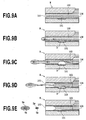
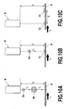
- a liquid in a flow path 102 is foamed by heat of the electro-thermal converter 101 (see Figs. 9B and 9C), and by utilizing the foam energy of air bubbles B generated at this time, the liquid can be ejected from an ejection port 103.
- the air bubbles B defoam as shown in Figs. 9D and 9E.
- a movable valve 104 is provided in the flow path 102 in order to effectively cause the foam energy of the air bubbles B to act in the direction of the ejection port 103.
- An ink jet printing apparatus using such a print head H is capable of printing an image on a printing medium by applying the liquid ejected from the ejection port 103. In the printing apparatus, demand for higher speed printing has been increased.
- a new problem has become apparent as the printing speed increases.
- main-droplet when dividing a liquid column pushed out from the ejecting port 103 to form droplet (main-droplet), sub-droplet Ds referred to as satellite is also formed along with main-droplet Dm as shown in Fig. 9E.
- main-droplet Dm and sub-droplet Ds have landed on the printing medium deviated from each other, the image quality of the printed image may deteriorate.
- Fig. 9D when dividing a liquid column pushed out from the ejecting port 103 to form droplet (main-droplet), sub-droplet Ds referred to as satellite is also formed along with main-droplet Dm as shown in Fig. 9E.
- main-droplet Dm and sub-droplet Ds have landed on the printing medium deviated from each other, the image quality of the printed image may deteriorate.
- Fig. 9D when dividing a liquid column pushed out from the ejecting port 103
- the ejecting timing of the sub-droplet Ds is later than that of the main-droplet Dm, and the ejecting speed Vs of the sub-droplet D is lower than the ejecting speed Vm of the main-droplet Dm. Therefore, as the relative moving speed Vf of the head H and the printing medium W becomes higher, deviation d of the landing positions of the main-droplet Dm and the sub-droplet Ds becomes larger (see Figs. 10B and 10C).
- Figs. 10A, 10B, and 10C illustrate that the printing medium W moves against the head H.
- D1 is a dot formed on the printing medium W by a main-droplet Dm
- D2 is a dot formed on the printing medium W by a sub-droplet Ds.
- a distance h (see Fig. 10A) between an ejection port face (face where the ejection port is located) of the printing head and the printing medium is narrowed, or the ejecting speed of a liquid is increased.
- Japanese Patent Laid-Open No. 2000-263788 describes a configuration for matching the ejecting directions of main-droplet and sub-droplet of ink.
- a nozzle portion including an ejection port and a flow path is formed of a plurality of materials, a difference in surface energy among the materials, in other words, a difference in wettability to the ink occurs.
- the configuration described in Japanese Patent Laid-Open No. 2000-263788 is provided focusing on the fact that the deviation in the ejecting directions of the main-droplet and the satellite occurs due to such difference in wettability to the ink.
- the ejection port face is inclined so that the part of the flow path on the side where a material with less surface energy is located is made shorter than the part of the flow path on the side where a material with more surface energy is located. This causes the ejecting directions of the main-droplet and the satellite to be made coincident.
- Japanese Patent Laid-Open No. 2000-263788 only discloses a configuration for matching the ejecting directions of the main-droplet and the sub-droplet as shown in Fig. 10A.
- a conf iguration solving the problem associated with the increase in the printing speed as shown in Figs. 10B and 10C, i.e. , suppressing the increase in deviation of the landing positions of the main-droplet and the sub-droplet cannot be achieved.
- the deviation of the landing positions of the main-droplet and the sub-droplet that increased along with the increase in printing speed could not be sufficiently suppressed.
- complying with a request desired for an ink jet printing apparatus for industrial use was difficult, i.e., a request for higher printing speed and higher quality of printed image.
- the deviation of landing positions of the main-droplet and the sub-droplet will be critical. Barcodes are printed information made of combinations of black bars and white spaces different in thickness.
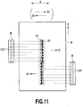
- Figs. 11, 12A, and 12B are explanatory views of printing results in the case of landing positions of the main-droplet and the sub-droplet deviated in so-called serial scan type and full line type ink jet printing apparatuses.
- an image is sequentially printed on the printing medium W by repeating an operation of ejecting a liquid while the head H moves in the main scanning direction of an arrow X and an operation of conveying the printing medium W in the sub-scanning direction of an arrow Y.
- the printing method in Fig. 11 is a bi-directional printing method that prints the image when the head H moves both in the forward direction of an arrow X1 and in the backward direction of an arrow X2.
- a dot D2 is formed deviated from the center of a dot D1 in the traveling direction (X1 direction) of the head H.
- the dot D2 is formed deviated from the center of the dot D1 in the traveling direction (X2 direction) of the head H.
- the scanning speed moving speed in the arrows X1 and X2 directions
- the dot D2 is formed within the dot D1 as shown in Fig. 11.
- the scanning speed becomes high, the dot D2 is formed outside the dot D1.
- an image is continuously printed on the printing medium W by ejecting a liquid from the head H while continuously conveying the printing medium W in the arrow Y1 direction with the head H being fixed.
- the dot D2 is formed deviated from the center of the D1 in the direction opposite (arrow Y2 direction) the conveying direction (arrow Y1) of the printing medium W.
- the arrow Y2 direction is a relative moving direction of the head H against the printing medium W.
- the dot D2 is formed outside the dot D1 as shown in Fig. 12B.
- the barcodes may be unable to be read.
- the present invention provides a printing head, an ink jet printing apparatus, and an ink jet printing method that enable to print a high quality image while achieving high speed printing.
- the present invention in its first aspect provides an in jet printing head as specified in claims 1 to 9.
- the present invention in its second aspect provides an in jet printing apparatus as specified in claims 10 to 12.
- the present invention in its third aspect provides an in jet printing method as specified in claim 13.
- a normal line of the ejection port face of the printing head where the ejection port is located is formed to intersect with an axis line of the nozzle at a predetermined angle, and the ejection port face inclines in the direction associated with the relative moving direction of the printing head and the printing medium.
- proactive differentiation of the ejecting directions of the main-droplet and the sub-droplet keeps the deviation of the landing positions of the main-droplet and the sub-droplet on the printing medium small, and a high quality image can be printed while achieving the high speed printing.
- Fig. 1 is a partially cut-out perspective view of main parts of a printing head according to a first embodiment of the present invention
- FIG. 2A, 2B, 2C, 2D, and 2E is an explanatory view of an ejecting process of a liquid at the printing head of Fig. 1;
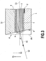
- Fig. 3 is an explanatory view of an inclination angle of an ejection port at the printing head of Fig. 1;
- Fig. 4 is an explanatory view of an ejecting direction of the liquid at the printing head of Fig. 1;
- FIG. 5A, 5B , and 5C is an explanatory view of landing positions of droplets ejected from the printing head of Fig. 1;
- Fig. 6 is an exploded perspective view of the printing head of Fig. 1;
- Fig. 7 is a schematic front view of an ink jet printing apparatus having the printing head of Fig. 1;
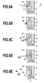
- FIG. 8A , 8B , 8C , 8D, and 8E is an explanatory view of an ejecting process of a liquid at a printing head according to a second embodiment of the present invention
- FIG. 9A, 9B, 9C, 9D, and 9E is an explanatory view of an ejecting process of a liquid at a printing head of a conventional art
- FIG. 10A, 10B, and 10C is an explanatory view of landing positions of droplets ejected from the printing head of Fig. 9A;
- Fig. 11 is an explanatory view of a printing example printed by a serial scan type ink jet printing apparatus using the printing head of Fig. 9A;
- FIG. 12A and 12B is an explanatory view of a printing example printed by a full line type ink jet printing apparatus using the printing head of Fig. 9A.
- Fig. 6 is an exploded perspective view of a printing head according to a first embodiment of the present invention.
- the printing head of the present embodiment is used in an ink jet printing apparatus as a printing head 110 for ejecting a liquid ink.
- Reference numeral 111 denotes an ejecting element equipped with an electro-thermal converter (air bubble generating device), a common liquid chamber, a flow path, an ejectionport, etc. , as described below, and 112 denotes a ceramic plate arranged with an electric wiring board as described below.
- the common liquid chamber in the ejecting element 111 is connected to a plurality of flow paths provided inside of flow path forming members. An ink is supplied to an ink supply port of the flow path forming members from an ink tank not shown.
- a plurality of nozzles are formed in alignment with flow paths, ejection ports, electro-thermal converters (air bubble generating devices), etc.
- the ink introduced into the common liquid chamber from the ink supply port is ejected from the ejection port of each nozzle.
- Fig. 7 is a schematic front view of a full line type ink jet printing apparatus 120 capable of printing an image using the printing head 110.
- the printing apparatus 120 is provided with a conveying portion 121 that conveys a printing medium W such as paper in the conveying direction of an arrow Y1 and a feeding portion 122 that supplies the printing medium W to the conveying portion 121.
- Six printing heads 110 are removably mounted on the printing apparatus 120 of the present embodiment. Inks of yellow (Y), light magenta (LM), magenta (M), light cyan (LC), cyan (C), and black (K) from corresponding cartridges 123 are supplied to these printing heads 110 .
- the six printing heads 110 are placed deviated in the conveying direction of the printing medium W.
- a nozzle alignment of each printing head 110 extends in an intersecting direction (perpendicular direction in the present embodiment) against the conveying direction of the printing medium W.
- Reference numeral 124 denotes a recovering unit that conducts a recovering process to maintain a good ejecting state of the ink of the printing head 110.
- the recovering process may include, for example, a process for suction-ejecting or pressure-ejecting the ink that do not contribute to the printing of an image from the ejection port and a process for ejecting (preliminary-ejection) the ink that do not contribute to the printing of the image from the ejection port.
- the recovering process may further include a process for wiping an ejection port face (face where the ejection port is located) of the printing head 110.
- Reference numeral 125 denotes an operation panel portion for operating the printing apparatus 12.
- Fig. 1 is a partially cut-out perspective view of a part near the nozzle of the printing head 110.
- a plurality of heaters (electro-thermal converters) 2 for heating and foaming ink are placed on a heater board 1.
- Resistors such as tantalum nitride are used for the heaters 2 whose thickness, for example, is 0.01 to 0.5 ⁇ m, and whose sheet resistance value is 10 to 300 O per unit square.
- Electrodes (not shown) of aluminum for conduction are connected to the heaters 2.
- switching transistors (not shown) for controlling the conduction with the heaters 2 are connected.
- the switch transistors are drive controlled by IC composed of circuits of gate devices for controlling, etc. , and control the heaters 2 in accordance with signals from the printing apparatus.
- the heaters 2 are formed at each of a plurality of flow paths 3. One end of each flow path 3 is communicated with a corresponding ejection port 4, and the other end of each flow path 3 is communicated with a common liquid chamber 5.
- the flow path 3 is surrounded by a heater board 1, nozzle walls 6, nozzle bank 7 of about 5-10 ⁇ m in thickness, and a top plate nozzle 8 of about 2 ⁇ m in thickness to form a tubular shape.
- the nozzle walls 6, the nozzle bank 7, and the top plate nozzle 8 are formed of photosensitive epoxy resin.
- a movable valve 9 is provided in the flow path 3, and a free end 9A of the movable valve 9 is located near the ejection port 4, while the base end is located near the common liquid chamber 5.
- a supporting point at the base end of the movable valve 9 is attached to a valve supporting member 10, and the valve supporting member 10 is attached to the heater board 1 by a valve base 11 (see Fig. 2A).
- the top plate nozzle 8 is attached to a top plate 12 formed of Si, etc.
- an ink supply port not shown is formed by anisotropic etching, etc.
- a liquid ink is supplied into the common liquid chamber 5 from outside through the ink supply port, and the ink in the common liquid chamber 5 is supplied into each flow path 3.
- An ejection port face F where the ejection ports 4 are located has a predetermined inclination of angle ⁇ as follows .
- the ejection port face F is not perpendicular to the axis line (axis line of the nozzle) L1 of the flow path 3, but the normal line L2 of the ejection port face F and the axis line L1 incline at the angle ⁇ .
- the ejection port face F is formed such that the normal line L2 intersects with the axis line L1 of the nozzle at the predetermined angle ⁇ .
- the ejection port face F is inclined to face in the opposite direction (arrow Y2 direction) of the conveying direction Y1 of the printing medium W, i.e., to face in the relative moving direction of the printing head 110 with the printing medium W as a reference.
- the ejection port face F is formed by inclining a face F0, which is perpendicular to the axis line L1, at the angle ⁇ toward the relative moving direction (arrow Y2 direction) of the printing head 110.
- the size of the angle ⁇ is established, as described below, taking into account the relative moving speed of the printing medium W and the printing head 10, etc.
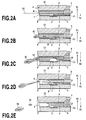
- Figs. 2A to 2E are explanatory views of the ejecting process of droplets of the ink from the ejection port 4.
- Fig. 2A illustrates a state before the ink in the flow path 3 is heated, i.e., a state of the heater 2 not energized.
- the ink near the ejection port 4 forms a meniscus M.
- Figs. 2B and 2C illustrate states of foam B generated with film boiling of ink, generated in the heated ink when the heater 2 is energized and heated.
- a propagation direction of the pressure based on the generation of the foam B is directed in the ejecting direction of the ink.
- the ink in the flow path 3 is ejected from ejection port 4 by the pressure generated by the foam and forms a liquid column such as the one shown in Fig. 2C as the foam B grows.
- Figs. 2D and 2E illustrate states of the foam B in the contraction process after the heating of the ink by the heater 2 has terminated.
- the ink near the ejection port 4 is drawn into the flow path 3 in accordance with the contraction of the foam B. Since the inertial force is acting in the ejecting direction at the tip portion of the liquid column, the liquid column is separated from the ink in the flow path 3.
- the separated liquid column forms main-droplet Dm and sub-droplet (satellite) Ds as a result of the surface tension of the ink and flies toward the printing medium.
- the meniscus M first starts to proceed in the ejection direction as the pressure generated by the foam propagates. This causes the ink near the ejection port 4 to be ejected from the ejection port 4 while maintaining the same contact angles a to the nozzle bank 7 and to the top plate nozzle 8 on the ejection port face F, as shown in Fig. 4.
- the angle defined by the ink ejection direction A1 and the axis line L1 of the flow path 3 will be the inclination angle ⁇ of the ejection port face F as shown in Fig. 3.
- the ink near the ejection port 4 is ejected in the arrow A1 direction along the normal line L2 perpendicular to the ejection port face F, as shown in Figs. 2B and 2C.
- the ink ejected in the arrow A1 direction will form the main-droplet Dm.
- the ink located near the heater 2 is ejected in the arrow A2 direction along the axis line L1 direction of the flow path 3.
- the ink ejected in the arrow A2 direction will form the sub-droplet Ds.
- the foam B enters into the contraction process, and the ink near the ejection port 4 is then drawn into the flow path 3 to form the main-droplet Dm and the sub-droplet Ds as shown in Fig. 2E. Since the directions of the main-droplet Dm and the sub-droplet Ds ejected by the foam are different, the main-droplet Dm flies in the arrow A1 direction (normal line L2 direction) at the angle ⁇ with the axis line L1, and the sub-droplet Ds flies in the arrow A2 direction (axis line L1 direction), as shown in Fig. 2E.
- the angle ⁇ of the ejection port face F i.e. the ejecting angle ⁇ of the main-droplet Dm, is set in compliance with a configuration of the printing apparatus 120 having the printing head 110 or in compliance with control conditions.
- One example of a setting method of the angle ⁇ will be described below based on Figs. 5A, 5B, and 5C.
- anejectingspeedofthemain-droplet Dm is Vm
- an ejecting speed of the sub-droplet Ds is Vs
- a conveying speed of the printing medium W is Vf
- a distance between the ejection port 4 and the printing medium W is h.
- the deviation amount d is generated in accordance with the ejecting speeds of the ink Vm and Vs, distance h, and conveying speed Vf, and the landing positions of the main-droplet Dm and the sub-droplet Ds cannot be made coincident.
- High-quality image can be printed by setting the angle ⁇ so as to satisfy the equation such as this to make coincident the landing positions of the main-droplet Dm and the sub-droplet Ds on the printing medium W.
- the printing head 110 of the first embodiment described above is a so-called edge shooter type, and the ejecting direction of the ink and the supplying direction of the ink into the nozzle approximately coincide.
- the present invention can also be applied to a so-called side shooter type printing head. In the side shooter type printing head, the ejecting direction of the ink and the supplying direction of the ink into the nozzle are different.
- Figs. 8A to 8E are sectional views of main parts of the side shooter type printing head applying the present invention, and identical elements are designated with identical reference numerals in the above embodiment and will not be described.
- the ejection port 4 is formed at a location of the top plate 12 facing the heater 2.
- the nozzle is formed by the heater 2, the flow path between the heater 2 and the ejection port 4, the ejection port 4, etc.
- the ejection port face F where the ejection port 5 is formed is inclined at the predetermined angle ⁇ against the axis line L1 of the nozzle, as described in the above embodiment.
- the ink in the common liquid chamber 5 is supplied into the nozzle from the arrow C direction in Fig. 8E.
- the printing head of the present example is capable of ejecting the ink utilizing the thermal energy of the heater 2, in the same way as the printing head in the above embodiment.
- the ink in the nozzle is foamed by the heat of the heater 2, and the droplets of the ink can be ejected from the ejection port 4 by utilizing the foam energy of the air bubbles B at this time. Since the ejection port face F is inclined at the angel ⁇ , the main-droplet Dm and the sub-droplet Ds ejected from the ejection port 4 are ejected in the same directions as stated in the above embodiment.
- the main-droplet Dm flies in the arrowA1 direction (normal line direction of the ejection port face) at the angle ⁇ with the axis line L1
- the sub-droplet Ds flies in the arrow A2 direction (axis line L1 direction).
- high-quality image can be printed by making coincident the landing positions of the main-droplet Dm and the sub-droplet Ds on the printing medium W.
- the present invention can be applied to a printing head (liquid ejecting head) capable of ejecting various liquids used directly or indirectly for image printing.
- the ejecting method of the liquid of the printing head may be a method using an electro-thermal converter (heater), as well as a method using a piezo-element, etc.
- the movable valve 10 does not always have to be provided in an edge shooter type printing head such as the one described in the first embodiment.
- the present invention can also be applied to the full line type ink jet printing apparatus shown in Fig. 7 as well as to the serial scan type ink jet printing apparatus described above.
- the ejection port only needs to be provided with a predetermined inclination angle in association with the relative moving direction of the head and the printing medium.
- the face (ejection port face F) on which the ejection port is formed only needs to be inclined such that the ejection port inclines and opens in the direction (arrow Y2) in which the head relatively moves against the printing medium.
- the axis line (L1) of the nozzle and the normal line (L2) of the ejection port face (F) where the ejection port is located are not coincident, but intersect at the predetermined angle instead.
- the nozzle walls 6, the nozzle bank 7, and the top plate nozzle 8 defining peripheral surfaces of the ejection port are made of the same material, and their physical characteristics are the same.
- at least the top plate nozzle 8 in the arrow Y1 direction and the nozzle bank 7 in the arrow Y2 direction may be formed of the same material.
- Their physical characteristics may include at least one of wettability to liquid or surface roughness.
- the materials forming the peripheral parts of the ejection port may be different.
- an orifice plate in which an ejection port is formed may be attached to the aperture of the liquid flow path.
- the inclination angle of the ejection port only needs to be optimally set considering the difference in ejecting directions of the main-droplet and the sub-droplet resulting from the physical characteristics.
- the present invention provides a printing head, an ink jet printing apparatus, and an ink jet printing method capable of achieving high-speed printing while realizing high-quality image.
- An ejection port face (F) where an ejection port (4) of the printing head is located is formed so that the normal line (L2) thereof intersects with an axis line (L1) of a nozzle at a predetermined angle ( ⁇ ).
- the ejection port face (F) inclines in a relative moving direction (Y2) of the printing head with a printing medium as a reference.
Landscapes
- Particle Formation And Scattering Control In Inkjet Printers (AREA)
- Ink Jet (AREA)
Priority Applications (1)
| Application Number | Priority Date | Filing Date | Title |
|---|---|---|---|
| EP10177597A EP2269825A3 (en) | 2006-04-19 | 2007-04-03 | Printing head, ink jet printing apparatus, and ink jet printing method |
Applications Claiming Priority (1)
| Application Number | Priority Date | Filing Date | Title |
|---|---|---|---|
| JP2006116101A JP2007283720A (ja) | 2006-04-19 | 2006-04-19 | 記録ヘッドおよびインクジェット記録装置 |
Publications (1)
| Publication Number | Publication Date |
|---|---|
| EP1847393A1 true EP1847393A1 (en) | 2007-10-24 |
Family
ID=38265501
Family Applications (2)
| Application Number | Title | Priority Date | Filing Date |
|---|---|---|---|
| EP07105526A Withdrawn EP1847393A1 (en) | 2006-04-19 | 2007-04-03 | Printing head, ink jet printing apparatus, and ink jet printing method |
| EP10177597A Withdrawn EP2269825A3 (en) | 2006-04-19 | 2007-04-03 | Printing head, ink jet printing apparatus, and ink jet printing method |
Family Applications After (1)
| Application Number | Title | Priority Date | Filing Date |
|---|---|---|---|
| EP10177597A Withdrawn EP2269825A3 (en) | 2006-04-19 | 2007-04-03 | Printing head, ink jet printing apparatus, and ink jet printing method |
Country Status (4)
| Country | Link |
|---|---|
| US (1) | US7762649B2 (enExample) |
| EP (2) | EP1847393A1 (enExample) |
| JP (1) | JP2007283720A (enExample) |
| CN (2) | CN101804728A (enExample) |
Cited By (1)
| Publication number | Priority date | Publication date | Assignee | Title |
|---|---|---|---|---|
| EP2269825A2 (en) | 2006-04-19 | 2011-01-05 | Canon Finetech Inc. | Printing head, ink jet printing apparatus, and ink jet printing method |
Families Citing this family (4)
| Publication number | Priority date | Publication date | Assignee | Title |
|---|---|---|---|---|
| JP5701000B2 (ja) | 2010-10-07 | 2015-04-15 | キヤノン株式会社 | インクジェット記録ヘッドおよびその製造方法 |
| KR20120052043A (ko) * | 2010-11-15 | 2012-05-23 | 삼성전자주식회사 | 잉크젯 프린트용 기판의 표면 개질 방법 |
| KR101701675B1 (ko) * | 2016-06-22 | 2017-02-02 | 한양대학교 에리카산학협력단 | 나노/마이크로 구조체 제조 장치 및 그 제조 방법 |
| CN117021814A (zh) * | 2022-03-29 | 2023-11-10 | 迪盛(武汉)微电子科技有限公司 | 一种喷墨打印方法及喷墨打印装置 |
Citations (7)
| Publication number | Priority date | Publication date | Assignee | Title |
|---|---|---|---|---|
| JPS60262660A (ja) * | 1984-06-12 | 1985-12-26 | Seiko Epson Corp | インクジエツト記録装置 |
| EP0661158A2 (en) * | 1994-01-03 | 1995-07-05 | Xerox Corporation | Ink jet printing |
| EP1020288A2 (en) * | 1999-01-12 | 2000-07-19 | Hewlett-Packard GmbH | Ink jet printing apparatus and method for controlling drop shape |
| JP2000263788A (ja) | 1999-03-16 | 2000-09-26 | Canon Inc | インクジェット記録ヘッド |
| JP2000334971A (ja) * | 1999-05-28 | 2000-12-05 | Canon Inc | インクジェットヘッドの製造方法 |
| EP1197335A1 (en) * | 2000-10-11 | 2002-04-17 | Hewlett-Packard Company | Inkjet nozzle structure to reduce drop placement error |
| JP2002292862A (ja) * | 2001-03-30 | 2002-10-09 | Olympus Optical Co Ltd | インクヘッド |
Family Cites Families (6)
| Publication number | Priority date | Publication date | Assignee | Title |
|---|---|---|---|---|
| ES2095862T3 (es) * | 1989-09-18 | 1997-03-01 | Canon Kk | Cabezal para la impresion por chorros de liquido y aparato para la impresion por chorros de liquido que lo utiliza. |
| JP2887971B2 (ja) * | 1991-08-27 | 1999-05-10 | 富士ゼロックス株式会社 | サーマルインクジェットヘッド |
| JPH06191035A (ja) * | 1992-12-25 | 1994-07-12 | Canon Inc | インクジェット記録ヘッドおよびインクジェット記録装置 |
| JP3495921B2 (ja) * | 1998-08-21 | 2004-02-09 | キヤノン株式会社 | 液体吐出方法、液体吐出ヘッドおよび液体吐出装置 |
| JP2005289012A (ja) * | 2004-04-05 | 2005-10-20 | Canon Finetech Inc | インクジェット記録装置および記録ヘッド |
| JP2007283720A (ja) | 2006-04-19 | 2007-11-01 | Canon Finetech Inc | 記録ヘッドおよびインクジェット記録装置 |
-
2006
- 2006-04-19 JP JP2006116101A patent/JP2007283720A/ja active Pending
-
2007
- 2007-03-26 US US11/691,145 patent/US7762649B2/en not_active Expired - Fee Related
- 2007-04-03 EP EP07105526A patent/EP1847393A1/en not_active Withdrawn
- 2007-04-03 EP EP10177597A patent/EP2269825A3/en not_active Withdrawn
- 2007-04-19 CN CN201010171105A patent/CN101804728A/zh active Pending
- 2007-04-19 CN CNA2007100966178A patent/CN101058256A/zh active Pending
Patent Citations (7)
| Publication number | Priority date | Publication date | Assignee | Title |
|---|---|---|---|---|
| JPS60262660A (ja) * | 1984-06-12 | 1985-12-26 | Seiko Epson Corp | インクジエツト記録装置 |
| EP0661158A2 (en) * | 1994-01-03 | 1995-07-05 | Xerox Corporation | Ink jet printing |
| EP1020288A2 (en) * | 1999-01-12 | 2000-07-19 | Hewlett-Packard GmbH | Ink jet printing apparatus and method for controlling drop shape |
| JP2000263788A (ja) | 1999-03-16 | 2000-09-26 | Canon Inc | インクジェット記録ヘッド |
| JP2000334971A (ja) * | 1999-05-28 | 2000-12-05 | Canon Inc | インクジェットヘッドの製造方法 |
| EP1197335A1 (en) * | 2000-10-11 | 2002-04-17 | Hewlett-Packard Company | Inkjet nozzle structure to reduce drop placement error |
| JP2002292862A (ja) * | 2001-03-30 | 2002-10-09 | Olympus Optical Co Ltd | インクヘッド |
Cited By (1)
| Publication number | Priority date | Publication date | Assignee | Title |
|---|---|---|---|---|
| EP2269825A2 (en) | 2006-04-19 | 2011-01-05 | Canon Finetech Inc. | Printing head, ink jet printing apparatus, and ink jet printing method |
Also Published As
| Publication number | Publication date |
|---|---|
| US20070247493A1 (en) | 2007-10-25 |
| CN101058256A (zh) | 2007-10-24 |
| JP2007283720A (ja) | 2007-11-01 |
| EP2269825A2 (en) | 2011-01-05 |
| EP2269825A3 (en) | 2011-03-09 |
| US7762649B2 (en) | 2010-07-27 |
| CN101804728A (zh) | 2010-08-18 |
Similar Documents
| Publication | Publication Date | Title |
|---|---|---|
| JP3675272B2 (ja) | 液体吐出ヘッドおよびその製造方法 | |
| US8651625B2 (en) | Fluid ejection device | |
| EP2030791A1 (en) | Liquid ejection head, inkjet printing apparatus and liquid ejecting method | |
| CN101797841A (zh) | 喷墨打印头 | |
| EP1287995B1 (en) | Liquid ejection head and image-forming apparatus using the same | |
| US7762649B2 (en) | Printing head, ink jet printing apparatus, and ink jet printing method ejecting main and sub-droplets | |
| US6471321B1 (en) | Ink jet recording apparatus and ink jet recording head | |
| JP4724490B2 (ja) | 液体吐出ヘッド | |
| US20070176976A1 (en) | Print head | |
| EP3429856B1 (en) | Fluid ejection device with a portioning wall | |
| US20030058305A1 (en) | Method for ejecting liquid, liquid ejection head and image-forming apparatus using the same | |
| JP4574385B2 (ja) | インクジェット記録ヘッドおよび記録装置 | |
| US9138995B2 (en) | Liquid ejection head, liquid ejection method, and printing apparatus employing this ejection head | |
| CN109070588B (zh) | 流体喷射装置 | |
| JP4018272B2 (ja) | インクジェットプリントヘッド及び該ヘッドを搭載するインクジェットプリンティングデバイス | |
| JP2002166571A (ja) | 記録ヘッドのバッファ室への気泡充填方法および記録装置 | |
| US10780705B2 (en) | Fluid ejection device | |
| JP2006224443A (ja) | インクジェット記録ヘッド、記録装置、および記録方法 | |
| JP2008120040A (ja) | 記録ヘッド、記録ヘッドの製造方法、インクジェット記録装置、インクジェット記録方法 | |
| HK1108410A (en) | Printing head, ink jet printing apparatus, and ink jet printing method | |
| JP2006192912A (ja) | 画像形成装置 | |
| JP2005193446A (ja) | 液滴吐出ヘッド、ヘッドカートリッジ及びインクジェット記録装置 |
Legal Events
| Date | Code | Title | Description |
|---|---|---|---|
| PUAI | Public reference made under article 153(3) epc to a published international application that has entered the european phase |
Free format text: ORIGINAL CODE: 0009012 |
|
| 17P | Request for examination filed |
Effective date: 20070403 |
|
| AK | Designated contracting states |
Kind code of ref document: A1 Designated state(s): AT BE BG CH CY CZ DE DK EE ES FI FR GB GR HU IE IS IT LI LT LU LV MC MT NL PL PT RO SE SI SK TR |
|
| AX | Request for extension of the european patent |
Extension state: AL BA HR MK YU |
|
| AKX | Designation fees paid |
Designated state(s): DE FR GB |
|
| RAP1 | Party data changed (applicant data changed or rights of an application transferred) |
Owner name: CANON FINETECH INC. |
|
| 17Q | First examination report despatched |
Effective date: 20100520 |
|
| STAA | Information on the status of an ep patent application or granted ep patent |
Free format text: STATUS: THE APPLICATION IS DEEMED TO BE WITHDRAWN |
|
| 18D | Application deemed to be withdrawn |
Effective date: 20101001 |