EP1847292B1 - Aktives medizinisches implantierbares Gerät mit mindestens zwei diagnostischen und/oder therapeutischen Funktionen - Google Patents
Aktives medizinisches implantierbares Gerät mit mindestens zwei diagnostischen und/oder therapeutischen Funktionen Download PDFInfo
- Publication number
- EP1847292B1 EP1847292B1 EP07006125A EP07006125A EP1847292B1 EP 1847292 B1 EP1847292 B1 EP 1847292B1 EP 07006125 A EP07006125 A EP 07006125A EP 07006125 A EP07006125 A EP 07006125A EP 1847292 B1 EP1847292 B1 EP 1847292B1
- Authority
- EP
- European Patent Office
- Prior art keywords
- implant
- modules
- bus system
- module
- implant according
- Prior art date
- Legal status (The legal status is an assumption and is not a legal conclusion. Google has not performed a legal analysis and makes no representation as to the accuracy of the status listed.)
- Not-in-force
Links
- 239000007943 implant Substances 0.000 title claims abstract description 80
- 230000001225 therapeutic effect Effects 0.000 title claims abstract description 9
- 230000008878 coupling Effects 0.000 claims abstract description 17
- 238000010168 coupling process Methods 0.000 claims abstract description 17
- 238000005859 coupling reaction Methods 0.000 claims abstract description 17
- 238000004891 communication Methods 0.000 claims abstract description 10
- 238000005516 engineering process Methods 0.000 claims description 6
- 210000001124 body fluid Anatomy 0.000 claims description 2
- 239000010839 body fluid Substances 0.000 claims description 2
- 230000001939 inductive effect Effects 0.000 claims description 2
- 238000002560 therapeutic procedure Methods 0.000 description 9
- 230000000638 stimulation Effects 0.000 description 8
- 201000010099 disease Diseases 0.000 description 6
- 208000037265 diseases, disorders, signs and symptoms Diseases 0.000 description 6
- 230000009885 systemic effect Effects 0.000 description 5
- NOESYZHRGYRDHS-UHFFFAOYSA-N insulin Chemical compound N1C(=O)C(NC(=O)C(CCC(N)=O)NC(=O)C(CCC(O)=O)NC(=O)C(C(C)C)NC(=O)C(NC(=O)CN)C(C)CC)CSSCC(C(NC(CO)C(=O)NC(CC(C)C)C(=O)NC(CC=2C=CC(O)=CC=2)C(=O)NC(CCC(N)=O)C(=O)NC(CC(C)C)C(=O)NC(CCC(O)=O)C(=O)NC(CC(N)=O)C(=O)NC(CC=2C=CC(O)=CC=2)C(=O)NC(CSSCC(NC(=O)C(C(C)C)NC(=O)C(CC(C)C)NC(=O)C(CC=2C=CC(O)=CC=2)NC(=O)C(CC(C)C)NC(=O)C(C)NC(=O)C(CCC(O)=O)NC(=O)C(C(C)C)NC(=O)C(CC(C)C)NC(=O)C(CC=2NC=NC=2)NC(=O)C(CO)NC(=O)CNC2=O)C(=O)NCC(=O)NC(CCC(O)=O)C(=O)NC(CCCNC(N)=N)C(=O)NCC(=O)NC(CC=3C=CC=CC=3)C(=O)NC(CC=3C=CC=CC=3)C(=O)NC(CC=3C=CC(O)=CC=3)C(=O)NC(C(C)O)C(=O)N3C(CCC3)C(=O)NC(CCCCN)C(=O)NC(C)C(O)=O)C(=O)NC(CC(N)=O)C(O)=O)=O)NC(=O)C(C(C)CC)NC(=O)C(CO)NC(=O)C(C(C)O)NC(=O)C1CSSCC2NC(=O)C(CC(C)C)NC(=O)C(NC(=O)C(CCC(N)=O)NC(=O)C(CC(N)=O)NC(=O)C(NC(=O)C(N)CC=1C=CC=CC=1)C(C)C)CC1=CN=CN1 NOESYZHRGYRDHS-UHFFFAOYSA-N 0.000 description 4
- 238000003745 diagnosis Methods 0.000 description 3
- 238000005259 measurement Methods 0.000 description 3
- 238000012544 monitoring process Methods 0.000 description 3
- NTYJJOPFIAHURM-UHFFFAOYSA-N Histamine Chemical compound NCCC1=CN=CN1 NTYJJOPFIAHURM-UHFFFAOYSA-N 0.000 description 2
- 102000004877 Insulin Human genes 0.000 description 2
- 108090001061 Insulin Proteins 0.000 description 2
- 230000000747 cardiac effect Effects 0.000 description 2
- HVYWMOMLDIMFJA-DPAQBDIFSA-N cholesterol Chemical compound C1C=C2C[C@@H](O)CC[C@]2(C)[C@@H]2[C@@H]1[C@@H]1CC[C@H]([C@H](C)CCCC(C)C)[C@@]1(C)CC2 HVYWMOMLDIMFJA-DPAQBDIFSA-N 0.000 description 2
- 230000000694 effects Effects 0.000 description 2
- 238000002513 implantation Methods 0.000 description 2
- 229940125396 insulin Drugs 0.000 description 2
- JVTAAEKCZFNVCJ-UHFFFAOYSA-N lactic acid Chemical compound CC(O)C(O)=O JVTAAEKCZFNVCJ-UHFFFAOYSA-N 0.000 description 2
- 238000000034 method Methods 0.000 description 2
- 239000000126 substance Substances 0.000 description 2
- 230000001133 acceleration Effects 0.000 description 1
- 230000006978 adaptation Effects 0.000 description 1
- QVGXLLKOCUKJST-UHFFFAOYSA-N atomic oxygen Chemical compound [O] QVGXLLKOCUKJST-UHFFFAOYSA-N 0.000 description 1
- 239000008280 blood Substances 0.000 description 1
- 210000004369 blood Anatomy 0.000 description 1
- 230000036760 body temperature Effects 0.000 description 1
- 238000009529 body temperature measurement Methods 0.000 description 1
- 230000007177 brain activity Effects 0.000 description 1
- 235000012000 cholesterol Nutrition 0.000 description 1
- 239000004020 conductor Substances 0.000 description 1
- 230000007547 defect Effects 0.000 description 1
- 238000013461 design Methods 0.000 description 1
- 239000003814 drug Substances 0.000 description 1
- 229940079593 drug Drugs 0.000 description 1
- 238000011156 evaluation Methods 0.000 description 1
- 229960001340 histamine Drugs 0.000 description 1
- 238000003780 insertion Methods 0.000 description 1
- 230000037431 insertion Effects 0.000 description 1
- 235000014655 lactic acid Nutrition 0.000 description 1
- 239000004310 lactic acid Substances 0.000 description 1
- 230000003287 optical effect Effects 0.000 description 1
- 239000013307 optical fiber Substances 0.000 description 1
- 229910052760 oxygen Inorganic materials 0.000 description 1
- 239000001301 oxygen Substances 0.000 description 1
- 230000008569 process Effects 0.000 description 1
- 238000012545 processing Methods 0.000 description 1
- 230000036387 respiratory rate Effects 0.000 description 1
Images


Classifications
-
- A—HUMAN NECESSITIES
- A61—MEDICAL OR VETERINARY SCIENCE; HYGIENE
- A61N—ELECTROTHERAPY; MAGNETOTHERAPY; RADIATION THERAPY; ULTRASOUND THERAPY
- A61N1/00—Electrotherapy; Circuits therefor
- A61N1/18—Applying electric currents by contact electrodes
- A61N1/32—Applying electric currents by contact electrodes alternating or intermittent currents
- A61N1/36—Applying electric currents by contact electrodes alternating or intermittent currents for stimulation
- A61N1/372—Arrangements in connection with the implantation of stimulators
- A61N1/375—Constructional arrangements, e.g. casings
- A61N1/3752—Details of casing-lead connections
-
- A—HUMAN NECESSITIES
- A61—MEDICAL OR VETERINARY SCIENCE; HYGIENE
- A61N—ELECTROTHERAPY; MAGNETOTHERAPY; RADIATION THERAPY; ULTRASOUND THERAPY
- A61N1/00—Electrotherapy; Circuits therefor
- A61N1/18—Applying electric currents by contact electrodes
- A61N1/32—Applying electric currents by contact electrodes alternating or intermittent currents
- A61N1/36—Applying electric currents by contact electrodes alternating or intermittent currents for stimulation
- A61N1/362—Heart stimulators
- A61N1/37—Monitoring; Protecting
-
- A—HUMAN NECESSITIES
- A61—MEDICAL OR VETERINARY SCIENCE; HYGIENE
- A61N—ELECTROTHERAPY; MAGNETOTHERAPY; RADIATION THERAPY; ULTRASOUND THERAPY
- A61N1/00—Electrotherapy; Circuits therefor
- A61N1/18—Applying electric currents by contact electrodes
- A61N1/32—Applying electric currents by contact electrodes alternating or intermittent currents
- A61N1/36—Applying electric currents by contact electrodes alternating or intermittent currents for stimulation
- A61N1/372—Arrangements in connection with the implantation of stimulators
- A61N1/375—Constructional arrangements, e.g. casings
- A61N1/37512—Pacemakers
-
- A—HUMAN NECESSITIES
- A61—MEDICAL OR VETERINARY SCIENCE; HYGIENE
- A61N—ELECTROTHERAPY; MAGNETOTHERAPY; RADIATION THERAPY; ULTRASOUND THERAPY
- A61N1/00—Electrotherapy; Circuits therefor
- A61N1/18—Applying electric currents by contact electrodes
- A61N1/32—Applying electric currents by contact electrodes alternating or intermittent currents
- A61N1/36—Applying electric currents by contact electrodes alternating or intermittent currents for stimulation
- A61N1/372—Arrangements in connection with the implantation of stimulators
- A61N1/37211—Means for communicating with stimulators
Definitions
- the invention relates to an active medical device implant having at least two diagnostic and / or therapeutic functions.
- a variety of different types of active implants are known in the art, such as cardiac pacemakers, defibrillators, insulin pumps, neurostimulators, body function recorders (so-called “event recorders”), cardiac assist systems, etc.
- These implants have in common that they are designed for a particular application and a have the functionality specified by the device manufacturer. The latter is usually aimed at a specific disease of the implant carrier, which is to be diagnosed and / or treated by the implant.
- an active medical device implant with a base device part in the form of an active implant, which is equipped with a central control unit and a bus system.
- Separate active implant modules can be coupled together via this bus system and communicate with and / or controlled by the central control unit.
- a diagnosis unit located on this particular module evaluates the signal and sends the message in the form of an encrypted signal via the bus system to the base unit part, where it is then evaluated by the central control unit.
- the central control unit determines a suitable therapy, which is then passed again in the form of a signal to the respective implant module. There the therapy is then carried out.
- Every single implant module is sort of a "specialist".
- the measured values can only be processed by a diagnostic unit assigned to the measuring implant module and located thereon, and consequently only perform an examination for a specific clinical picture. If, for example, a trade fair event which is completely unsuspected with regard to the disease to be determined by the associated diagnostic unit but which appears to be highly critical with respect to other clinical pictures, this possibly critical condition of the patient can not be recognized.
- a trade fair event which is completely unsuspected with regard to the disease to be determined by the associated diagnostic unit but which appears to be highly critical with respect to other clinical pictures, this possibly critical condition of the patient can not be recognized.
- the highly flexible individual use of such an implant is not possible, since only predefined states of the patient can be determined.
- a largely safe systemic monitoring is not guaranteed, namely, if due to a defect, the diagnostic functionality of the central control unit fails.
- the central control unit implements a master-and-slave control with regard to the hierarchical order of the implant modules in the control.
- the implant modules become even more independent of rigid, known implants, which makes the implant more easily adjustable to a complex disease or diagnostic need of a patient. Then much easier and more effective information can be processed or diagnosed in several places, for example. For example, a measured value can be recorded on an implant module, but this can not be processed in the same module because the diagnostic function is not present in this, but in another module. It is further advantageous that the measured value is indeed evaluated in the diagnostic unit of the measuring implant module, but then can be forwarded to a diagnostic unit of another implant module for further processing. As a result, the base unit part can be kept very small, since additional evaluation units are available decentralized and no longer need to be available in the base unit part.
- the base unit part accommodates cross-functional basic elements for the device implants, such as a central control unit, a communication unit and / or a power supply unit for the implant modules.
- a bus system for the coupling of the modules and in particular their control and / or communication, which is constructed for example of a plurality of electrical conductors or realized on the basis of optical fiber technology.
- the bus system can be designed so that the implant modules can be connected to their coupling signal technically and mechanically connected to the bus system, preferably can be stacked on it.
- the modules are thus "docked" to the bus system, for which purpose, for example, a feedthrough of the bus system through the individual modules is preferably provided by juxtaposing implant modules via plug-in couplings.
- the coupling of the modules can also take place via a wireless bus system, which is particularly advantageous if the individual implant modules after coupling should not form a compact, mechanical unit but should be placed distributed in the body.
- a wireless bus system which is particularly advantageous if the individual implant modules after coupling should not form a compact, mechanical unit but should be placed distributed in the body.
- Such wireless communication can be realized, for example, with a radio technology, such as "blue tooth", an inductive coupling or a galvanic coupling via a conductive body fluid.
- an implant module can be equipped with exchangeable submodules.
- the latter preferably deviate from the actual functionality of the implant module, so that the latter can be variably expanded in terms of its functional scope. This addition or even refitting can also take place at a later time after the first insertion of the device implant, without having to replace the complete implant.
- the device implant according to the invention allows a very flexible adaptation to diagnostic and therapeutic requirements, which even after a first use of the implant with limited effort and without having to replace the entire implant, is feasible.
- Fig. 1 The basic concept of the medical device implant 1 can be explained.
- This has various modules, namely a central control module 2, a power supply module 3 and a communication module 4, which is constructed for example on the basis of a transponder and via which the device implant 1 can communicate with an external base unit.
- the device implant 1 has two diagnostic measuring modules 5, 6 for measuring temperature and pressure and a therapeutic module 7 for electrical stimulation.
- a temperature sensor 8 is integrated in the measuring module 5, which serves the temperature measurement. This takes on a body implantation of the device implant in a patient's body.
- the measuring module 6 is used to determine the pressure P in a body part and for this purpose has a measuring line 9 emanating from the measuring module 6, at the free end of which a pressure sensor 10 is attached.
- the therapeutic module 7 has a connected catheter 11, at the free end of which stimulation electrodes 12 are seated.
- stimulation electrodes 12 are seated.
- a pacemaker function can be realized.
- the modules 2 to 7 are connected together via a bus system 13, which is coupled via interfaces 14 to the respective module 3 to 7 signal and energy supply technology.
- a base device part 15 represents the "backbone" of the medical device implant 1.
- a central control unit SE, a communication unit KE and a power supply unit EE are permanently installed as cross-functional basic elements.
- diagnostic and therapeutic modules for coupling to the base unit part 15 are now provided.
- the base unit part 15 in the long narrow side of its housing 16 on a coupling rail 17, which is formed by a corresponding housing groove.
- the measuring modules 18, 19, 20, 21 with their respective module head 22 to 25 can be inserted.
- the module heads 22 to 24 are in Fig. 2 drawn in a position in which they are not yet up to the end of the coupling rail 17 (left related to Fig. 2 ) are pushed through.
- the measuring module 21 and the therapy module 26 are shown in the not docked state.
- All measuring modules 18 to 21 have, starting from the module heads 22 to 25, measuring lines 27 to 29, at the free ends of which, in turn, measuring sensors 30 to 32, for example for pressure, pH or the like, are arranged.
- the temperature sensor 33 is inserted directly into the module head 22.
- the therapy module 26 has, on its module head 34, a catheter 35 which carries stimulation electrodes 36, 37 in front of and at its free end. Furthermore, a measuring sensor 38, for example, for pressure or temperature on the catheter 35 is provided.
- a final cap 39 is provided, which is placed on the last module head 34 and serves to complete the executed by the module heads 22 to 25, 34 bus system 13.
- the bus system 13 is constructed via the base unit part 15 and the modules 18 to 21, 26 through respective plug connections 40 between the module heads 22 to 25, 34 and to the base unit part 15.
- Fig. 3 shows a section of the catheter 35 in the region of the distal end. It can be seen that the measuring sensor 38 can itself be designed as an exchangeable submodule 41. This carries - as mentioned - a measuring sensor for z. B. pressure or temperature. The functionality of the sub-module 41 is thus of a diagnostic nature, while the stimulation electrodes 36, 37 effect a therapeutic effect on the therapy module 26.
- the sub-module 41 can be inserted into a corresponding receptacle 42 in the catheter 35.
- the coupling to the (not shown here) control module takes place via a connector 43 to the bus system thirteenth
- modules 18 to 21, 26, 41 can communicate with each other and with the central control module via the bus system 13 uni-, bi- or multi-directional.
- a master-and-slave control with respect to the hierarchical order of the modules 18 to 21, 26 can be implemented.
Landscapes
- Health & Medical Sciences (AREA)
- Life Sciences & Earth Sciences (AREA)
- Radiology & Medical Imaging (AREA)
- Engineering & Computer Science (AREA)
- Biomedical Technology (AREA)
- Nuclear Medicine, Radiotherapy & Molecular Imaging (AREA)
- Animal Behavior & Ethology (AREA)
- General Health & Medical Sciences (AREA)
- Public Health (AREA)
- Veterinary Medicine (AREA)
- Heart & Thoracic Surgery (AREA)
- Cardiology (AREA)
- Biophysics (AREA)
- Electrotherapy Devices (AREA)
- Measuring And Recording Apparatus For Diagnosis (AREA)
Description
- Die Erfindung betrifft ein aktives medizinisches Geräteimplantat mit mindestens zwei diagnostischen und/oder therapeutischen Funktionen.
- Aus dem Stand der Technik ist eine Vielzahl verschiedenartiger aktiver Implantate bekannt, wie beispielsweise Herzschrittmacher, Defibrillatoren, Insulinpumpen, Neurostimulatoren, Körperfunktionsaufzeichnungsgeräte (so genannte "Eventrecorder"), Herzunterstützungssysteme usw. Diesen Implantaten ist gemeinsam, dass sie für einen bestimmten Anwendungszweck ausgelegt sind und eine vom Gerätehersteller vorgegebene Funktionalität aufweisen. Letztere ist in der Regel auf eine bestimmte Erkrankung des Implantatträgers ausgerichtet, die durch das Implantat diagnostiziert und/oder therapiert werden soll.
- Viele Patienten haben jedoch nicht nur eine bestimmte Erkrankung, sondern mehrere oder systemische Krankheitsbilder, die einer Diagnose oder Therapie bedürfen. Ferner besteht oftmals auch nur der Bedarf nach einer systemischen Überwachung. Dies ist mit einem vorgegebenen Implantat in der Regel schwierig umzusetzen, da die hierfür notwendigen Einzelkomponenten in einem systemischen Zusammenhang stehen und sich gegenseitig beeinflussen.
- Jedoch ist beispielsweise aus der
US 6,141,588 ein aktives medizinisches Geräteimplantat mit einem Basisgeräteteil in Form eines aktiven Implantats bekannt, das mit einer zentralen Steuereinheit und einem Bussystem ausgestattet ist. Gesonderte aktive Implantatmodule können über dieses Bussystem miteinander gekoppelt werden und mit der zentralen Steuereinheit kommunizieren und/oder durch diese gesteuert werden. Die Implantatmodule nehmen jeweils einen Messwert auf, eine auf diesem jeweiligen Modul befindliche Diagnoseeinheit wertet das Signal aus und sendet die Nachricht in Form eines verschlüsselten Signals über das Bussystem an das Basisgeräteteil, wo es dann von der zentralen Steuereinheit ausgewertet wird. Die zentrale Steuereinheit ermittelt daraufhin eine geeignete Therapie, welche dann wieder in Form eines Signals an das jeweilige Implantatmodul geleitet wird. Dort wird dann die Therapie ausgeführt. - Nachteilig an dieser Lösung ist, dass jedes einzelne Implantatmodul sozusagen ein "Spezialist" ist. Die Messwerte können nur von einer dem messenden Implantatmodul zugeordneten und auf diesem befindliche Diagnoseeinheit prozessiert werden, folglich also auch nur eine Untersuchung auf ein bestimmtes Krankheitsbild vornehmen. Erfolgt beispielsweise ein Messevent, der bezüglich des von der zugeordneten Diagnoseeinheit zu bestimmenden Krankheitsbildes völlig unverdächtig ist, der aber in Bezug auf andere Krankheitsbilder höchst kritisch erscheint, kann dieser eventuell kritische Zustand des Patienten nicht erkannt werden. Somit ist der hochflexible individuelle Einsatz eines solchen Implantats nicht möglich, da nur vordefinierte Zustände des Patienten ermittelt werden können. Weiterhin ist eine weitgehend sichere systemische Überwachung nicht gewährleistet, nämlich dann, wenn aufgrund eines Defektes die Diagnosefunktionalität der zentralen Steuereinheit ausfällt.
- Aufgrund der geschilderten Problematik besteht also ein Bedürfnis für ein Implantat, das individuell auf ein komplexes Krankheitsbild oder Diagnosebedürfnis eines Patienten abstimmbar und so konfigurierbar ist, dass es im Bedarfsfall verschiedenartige Informationen ggf. an mehreren Stellen des Körpers aufnehmen, verarbeiten und wiederum ggf. darauf aufbauend eine angepasste Therapie ableiten und applizieren kann.
- Aufgabe der vorliegenden Erfindung ist es deshalb, ein aktives medizinisches Geräteimplantat zu schaffen, das vom Arzt während der Implantationsprozedur und im Betrieb den individuellen Bedürfnissen eines Patienten entsprechend konfigurierbar ist und eine sichere systemische Überwachung bietet, ohne dabei technisch aufwändig zu sein.
- Diese Aufgabe wird laut Patentanspruch 1 dadurch gelöst, dass die aktiven Implantatmodule des Geräteimplantats über das Bussystem zusätzlich untereinander uni-, bi- oder multidirektional kommunizieren.
- Damit es nicht zu Messungenauigkeiten oder gar Messfehlern kommen kann, implementiert die zentrale Steuereinheit bei der Steuerung eine Master-and-Slave-Steuerung bezüglich der hierarchischen Ordnung der Implantatmodule.
- Das bedeutet, dass die Implantatmodule noch unabhängiger von starren bekannten Implantaten werden, weshalb das Implantat auch noch leichter auf ein komplexes Krankheitsbild oder Diagnosebedürfnis eines Patienten einstellbar ist. Dann können auch wesentlich leichter und effektiver Informationen an mehreren Stellen beispielsweise verarbeitet bzw. diagnostiziert werden. Beispielsweise kann an einem Implantatmodul ein Messwert aufgenommen werden, der aber nicht im selben Modul verarbeitet werden kann, weil die Diagnosefunktion nicht in diesem, aber in einem anderen Modul vorhanden ist. Es ist weiter von Vorteil, dass der Messwert zwar in der Diagnoseeinheit des messenden Implantatmoduls ausgewertet wird, dann aber an eine Diagnoseeinheit eines anderen Implantatmoduls zur weiteren Verarbeitung weitergeleitet werden kann. Als Folge kann auch das Basisgeräteteil sehr klein gehalten werden, da zusätzliche Auswerteeinheiten dezentral vorhanden sind und nicht mehr im Basisgeräteteil verfügbar sein müssen.
- Aufgrund des Modulsystems können die einzelnen Module jeweils für einen bestimmten Anwendungszweck ausgelegt sein, wie z. B. für die Messung physikalischer oder chemischer Parameter und darauf basierend für die Berechnung physiologischer Parameter zu Diagnosezwecken. Darauf aufbauend wiederum kann eine bestimmte Therapie von dem aktiven Geräteimplantat appliziert werden. Als Beispiel für solche physikalischen und chemischen Parameter können genannt werden:
- Körpertemperatur
- elektrische Werte (Spannung, Strom, Impedanz)
- Druck
- Beschleunigung
- optische Werte (Farbe, Lichtdurchlässigkeit)
- Viskosität
- pH-Wert
- Zeit
- Daraus zu ermittelnde physiologische Parameter sind dann beispielsweise:
- Herzfrequenz
- Atemfrequenz
- Nerven- bzw. Hirnaktivität
- Sauerstoffsättigung
- Milchsäure-Konzentration
- Blutzucker-Gehalt
- Cholesterin-Gehalt
- Histamin-Gehalt
- Bewegung (Aktivität)
- Daraus ableitbare Therapien sind beispielsweise:
- elektrische Stimulation (nieder- und hochenergetisch), wie z. B. Herzschrittmacher oder Defibrillator
- mechanische Stimulation
- Medikamentengabe (z. B. Insulinpumpe)
- Grundsätzlich ist es auf der Basis dieses Konzeptes möglich, in einem Modul eine oder mehrere der vorstehend aufgeführten Funktionalitäten zu implementieren sowie Module mit Spezialaufgaben, wie beispielsweise die Stromversorgung der anderen Module oder die Kommunikation unter diesen vorzusehen. In diesem Zusammenhang kann es vorteilhaft sein, ein Basisgeräteteil vorzusehen, über das die Implantatmodule koppelbar sind. Damit ist das Gesamtsystem dann kompakt und "aufgeräumt" umsetzbar.
- Das Basisgeräteteil nimmt funktionsübergreifende Grundelemente für die Geräteimplantate auf, wie eine zentrale Steuereinheit, eine Kommunikationseinheit und/oder eine Energieversorgungseinheit für die Implantatmodule.
- Gemäß einer vorteilhaften Ausführungsform ist für die Kopplung der Module und insbesondere deren Steuerung und/oder Kommunikation ein Bussystem vorgesehen, das beispielsweise aus mehreren elektrischen Leitern aufgebaut oder auf der Basis der Lichtleitertechnik realisiert ist.
- Das Bussystem kann dabei so ausgelegt sein, dass die Implantatmodule zu ihrer Kopplung signaltechnisch und mechanisch mit dem Bussystem verbindbar, vorzugsweise darauf aneinanderreihbar sind. Die Module werden also an das Bussystem "angedockt", wozu beispielsweise eine Hindurchführung des Bussystems durch die Einzelmodule unter Aneinanderreihung von Implantatmodulen vorzugsweise über Steckkopplungen vorgesehen ist.
- Die Kopplung der Module kann jedoch auch über ein drahtloses Bussystem erfolgen, was besonders dann vorteilhaft ist, wenn die einzelnen Implantatmodule nach dem Koppeln keine kompakte, mechanische Einheit bilden sollen, sondern im Körper verteilt platziert werden sollen. Eine solche drahtlose Kommunikation kann beispielsweise mit einer Funktechnologie, wie "Blue Tooth", einer induktiven Kopplung oder einer galvanischen Kopplung über eine leitfähige Körperflüssigkeit realisiert werden.
- Gemäß einer weiteren bevorzugten Ausführungsform kann ein Implantatmodul mit austauschbaren Teilmodulen bestückt werden. Letztere weichen vorzugsweise von der eigentlichen Funktionalität des Implantatmoduls ab, sodass letzteres in seinem Funktionsumfang variabel erweitert werden kann. Diese Ergänzung oder auch Umbestückung kann auch zu einem späteren Zeitpunkt nach dem ersten Einsetzen des Geräteimplantats erfolgen, ohne das komplette Implantat tauschen zu müssen.
- Zusammenfassend erlaubt das erfindungsgemäße Geräteimplantat eine sehr flexible Anpassung an diagnostische und therapeutische Anforderungen, was auch nach einem Ersteinsetzen des Implantates noch mit begrenztem Aufwand und ohne das gesamte Implantat tauschen zu müssen, durchführbar ist.
- Weitere Merkmale, Vorteile und Einzelheiten der Erfindung ergeben sich aus der nachfolgenden Beschreibung eines Ausführungsbeispieles anhand der beigefügten Zeichnungen. Es zeigen:
- Fig. 1
- eine schematische Darstellung eines aktiven medizinischen Geräteimplantats in Modulbauweise,
- Fig. 2
- eine perspektivische Darstellung eines solchen Geräteimplantats mit verschiedenen Implantatmodulen, sowie
- Fig. 3
- eine ausschnittsweise Perspektivdarstellung eines Implantatmoduls.
- Anhand von
Fig. 1 kann das grundsätzliche Konzept des medizinischen Geräteimplantats 1 erläutert werden. Dieses weist verschiedene Module auf, nämlich ein zentrales Steuermodul 2, ein Stromversorgungsmodul 3 und ein Kommunikationsmodul 4, das beispielsweise auf der Basis eines Transponders aufgebaut ist und über das das Geräteimplantat 1 mit einem externen Basisgerät kommunizieren kann. Ferner weist das Geräteimplantat 1 zwei diagnostische Messmodule 5, 6 zur Messung von Temperatur und Druck sowie ein therapeutisches Modul 7 zur elektrischen Stimulation auf. In das Messmodul 5, das der Temperaturmessung dient, ist ein Temperatursensor 8 integriert. Dieser nimmt bei einer Einpflanzung des Geräteimplantats in einen Patientenkörper die Körpertemperatur auf. - Das Messmodul 6 dient der Ermittlung des Drucks P in einem Körperteil und weist hierzu eine vom Messmodul 6 ausgehende Messleitung 9 auf, an deren freiem Ende ein Drucksensor 10 angebracht ist.
- Das therapeutische Modul 7 weist einen angeschlossenen Katheter 11 auf, an dessen freiem Ende Stimulationselektroden 12 sitzen. Damit kann der Patientenkörper elektrisch stimuliert, also beispielsweise eine Herzschrittmacherfunktion realisiert werden.
- Die Module 2 bis 7 sind gemeinsam über ein Bussystem 13 miteinander verbunden, das über Schnittstellen 14 an das jeweilige Modul 3 bis 7 signal- und energieversorgungstechnisch gekoppelt ist.
- Anhand von
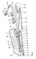
Fig. 2 ist eine Umsetzung des inFig. 1 schematisch dargestellten Modulsystems zu erläutern. So stellt ein Basisgeräteteil 15 das "Rückgrat" des medizinischen Geräteimplantats 1 dar. In diesem Basisgeräteteil 15 sind eine zentrale Steuereinheit SE, eine Kommunikationseinheit KE sowie eine Energieversorgungseinheit EE als funktionsübergreifende Grundelemente fest eingebaut. In dem gezeigten Ausführungsbeispiel sind nun diagnostische und therapeutische Module zur Ankopplung an das Basisgeräteteil 15 vorgesehen. Dazu weist das Basisgeräteteil 15 in der langen Schmalseite seines Gehäuses 16 eine Kopplungsschiene 17 auf, die durch eine entsprechende Gehäusenut gebildet ist. In diese sind mechanisch die verschiedenen dargestellten Module, nämlich beispielsweise die Messmodule 18, 19, 20, 21 mit ihrem jeweiligen Modulkopf 22 bis 25 einschiebbar. Die Modulköpfe 22 bis 24 sind dabei inFig. 2 in einer Stellung gezeichnet, in der sie noch nicht bis zum Ende der Kopplungsschiene 17 (links bezogen aufFig. 2 ) durchgeschoben sind. Das Messmodul 21 sowie das Therapiemodul 26 sind im noch nicht angedockten Zustand gezeigt. - Alle Messmodule 18 bis 21 weisen von den Modulköpfen 22 bis 25 ausgehend Messleitungen 27 bis 29 auf, an deren freien Enden wiederum Messsensoren 30 bis 32 beispielsweise für Druck, pH-Wert oder dergleichen angeordnet sind. Im Messmodul 18 ist der Temperatursensor 33 direkt in den Modulkopf 22 eingesetzt.
- Das Therapiemodul 26 weist an seinem Modulkopf 34 einen Katheter 35 auf, der vor und an seinem freien Ende Stimulationselektroden 36, 37 trägt. Ferner ist ein Messsensor 38 beispielsweise für Druck oder Temperatur am Katheter 35 vorgesehen.
- Zur Komplettierung des in
Fig. 2 gezeigten Geräteimplantats ist noch eine Abschlusskappe 39 vorgesehen, die auf den letzten Modulkopf 34 aufgesetzt wird und zum Abschluss des durch die Modulköpfe 22 bis 25, 34 durchgeführten Bussystems 13 dient. Das Bussystem 13 wird über das Basisgeräteteil 15 und die Module 18 bis 21, 26 durch jeweilige Steckverbindungen 40 zwischen den Modulköpfen 22 bis 25, 34 und zum Basisgeräteteil 15 hin aufgebaut. -
Fig. 3 zeigt ausschnittsweise den Katheter 35 im Bereich des distalen Endes. Daraus wird erkennbar, dass der Messsensor 38 wiederum selbst als austauschbares Teilmodul 41 ausgeführt sein kann. Dieses trägt - wie erwähnt - einen Messsensor für z. B. Druck oder Temperatur. Die Funktionalität des Teilmoduls 41 ist damit diagnostischer Natur, während die Stimulationselektroden 36, 37 am Therapiemodul 26 einen therapeutischen Effekt bewirken. - Das Teilmodul 41 ist in eine entsprechende Aufnahme 42 im Katheter 35 einsetzbar. Die Ankopplung an das (hier nicht dargestellte) Steuermodul erfolgt dabei über eine Steckverbindung 43 auf das Bussystem 13.
- Zu ergänzen ist, dass die Module 18 bis 21, 26, 41 untereinander und mit dem zentralen Steuermodul über das Bussystem 13 uni-, bi- oder multidirektional kommunizieren können. Bei der Steuerung kann eine Master-and-Slave-Steuerung bezüglich der hierarchischen Ordnung der Module 18 bis 21, 26 implementiert werden.
Claims (10)
- Aktives medizinisches Geräteimplantat mit mindestens zwei diagnostischen und/oder therapeutischen Funktionen, welches- ein Basisgeräteteil (15) mit einer zentrale Steuereinheit (SE) und einem Bussystem (13); und- für diese Funktionen jeweils gesonderte, miteinander über das Bussystem koppelbare, aktive Implantatmodule (18-21; 26) vorsieht,wobei die Implantatmodule über das Bussystem mit der zentralen Steuerung uni-, bi- oder multidirektional kommunizieren und durch diese gesteuert werden, und wobei die Implantatmodule untereinander über das Bussystem uni-, bi- oder multidirektional kommunizieren können.
- Geräteimplantat nach Anspruch 1, dadurch gekennzeichnet, dass die zentrale Steuereinheit (SE) bei der Steuerung eine Master-and-Slave-Steuerung bezüglich der hierarchischen Ordnung der Implantatmodule (18-21; 26) implementiert.
- Geräteimplantat nach Anspruch 1, dadurch gekennzeichnet, dass das Basisgeräteteil (15) weitere funktionsübergreifende Grundelemente (KE, EE) für die Geräteimplantate (18-21, 26) aufnimmt.
- Geräteimplantat nach Anspruch 3, dadurch gekennzeichnet, dass die weiteren funktionsübergreifenden Grundelemente eine Kommunikationseinheit (KE) und/oder eine Energieversorgungseinheit (EE) für die Implantatmodule (18-21, 26) als Grundelemente umfassen.
- Geräteimplantat nach Anspruch 1, dadurch gekennzeichnet, dass die Implantatmodule (18-21, 26) zu ihrer Kopplung signaltechnisch und mechanisch mit dem Bussystem (13) verbindbar, vorzugsweise auf einer Kopplungsschiene (17) aneinanderreihbar sind.
- Geräteimplantat nach Anspruch 5, dadurch gekennzeichnet, dass das Bussystem (13) durch die Implantatmodule (18-21, 26) durchgeführt und durch Aneinanderreihen von Implantatmodulen (18-21, 26) vorzugsweise über Steckkupplungen (40) erweiterbar ist.
- Geräteimplantat nach Anspruch 1, dadurch gekennzeichnet, dass das Bussystem (13) zur signal- und kommunikationstechnischen Kopplung der Implantatmodule (18-21, 26) drahtlos ausgeführt ist.
- Geräteimplantat nach Anspruch 7, dadurch gekennzeichnet, dass das drahtlose Bussystem auf Funkbasis, mittels induktiver Kopplung oder mittels galvanischer Kopplung über eine leitfähige Körperflüssigkeit realisiert ist.
- Geräteimplantat nach einem der vorgenannten Ansprüche, dadurch gekennzeichnet, dass ein Implantatmodul (26) mit mindestens einem austauschbaren Teilmodul (41) vorzugsweise mit vom Implantatmodul (26) abweichender Funktionalität bestückbar ist.
- Geräteimplantat nach einem der vorgenannten Ansprüche, dadurch gekennzeichnet, dass eines der Implantatmodule als Master-Gerät die Steuerung weiterer gekoppelter Implantatmodule übernimmt.
Applications Claiming Priority (1)
| Application Number | Priority Date | Filing Date | Title |
|---|---|---|---|
| DE102006018851A DE102006018851A1 (de) | 2006-04-22 | 2006-04-22 | Aktives medizinisches Geräteimplantat mit mindestens zwei diagnostischen und/oder therapeutischen Funktionen |
Publications (2)
| Publication Number | Publication Date |
|---|---|
| EP1847292A1 EP1847292A1 (de) | 2007-10-24 |
| EP1847292B1 true EP1847292B1 (de) | 2009-09-02 |
Family
ID=38066397
Family Applications (1)
| Application Number | Title | Priority Date | Filing Date |
|---|---|---|---|
| EP07006125A Not-in-force EP1847292B1 (de) | 2006-04-22 | 2007-03-24 | Aktives medizinisches implantierbares Gerät mit mindestens zwei diagnostischen und/oder therapeutischen Funktionen |
Country Status (4)
| Country | Link |
|---|---|
| US (1) | US8126545B2 (de) |
| EP (1) | EP1847292B1 (de) |
| AT (1) | ATE441456T1 (de) |
| DE (2) | DE102006018851A1 (de) |
Families Citing this family (118)
| Publication number | Priority date | Publication date | Assignee | Title |
|---|---|---|---|---|
| US8527054B2 (en) * | 2009-06-30 | 2013-09-03 | Richard B. North | Implantable medical device connector |
| AU2011295633A1 (en) * | 2010-08-31 | 2013-04-18 | Saluda Medical Pty Limited | Distributed implant systems |
| US9775982B2 (en) | 2010-12-29 | 2017-10-03 | Medtronic, Inc. | Implantable medical device fixation |
| WO2012155190A1 (en) | 2011-05-13 | 2012-11-22 | National Ict Australia Ltd | Method and apparatus for measurement of neural response |
| WO2012155189A1 (en) | 2011-05-13 | 2012-11-22 | National Ict Australia Ltd | Method and apparatus for estimating neural recruitment - f |
| EP2707096B1 (de) | 2011-05-13 | 2018-08-22 | Saluda Medical Pty Limited | Vorrichtung zur messung einer neuronalen reaktion |
| WO2012155185A1 (en) | 2011-05-13 | 2012-11-22 | National Ict Australia Ltd | Method and apparatus for measurement of neural response |
| US9872990B2 (en) | 2011-05-13 | 2018-01-23 | Saluda Medical Pty Limited | Method and apparatus for application of a neural stimulus |
| DK2908904T3 (da) | 2012-11-06 | 2020-12-14 | Saluda Medical Pty Ltd | System til styring af vævs elektriske tilstand |
| DK2908905T3 (da) | 2012-11-06 | 2020-12-14 | Saluda Medical Pty Ltd | System til at kontrollere elektriske forhold i væv |
| CN105848575B (zh) | 2013-11-15 | 2019-11-19 | 萨鲁达医疗有限公司 | 监控大脑神经电位 |
| WO2015074121A1 (en) | 2013-11-22 | 2015-05-28 | Saluda Medical Pty Ltd | Method and device for detecting a neural response in a neural measurement |
| US20150196769A1 (en) | 2014-01-10 | 2015-07-16 | Cardiac Pacemakers, Inc. | Methods and systems for improved communication between medical devices |
| EP3092034B1 (de) | 2014-01-10 | 2019-10-30 | Cardiac Pacemakers, Inc. | Systeme zur detektion von herzrhythmusstörungen |
| US20170135624A1 (en) | 2014-03-28 | 2017-05-18 | Saluda Medical Pty Ltd | Assessing Neural State from Action Potentials |
| CA2944042C (en) | 2014-05-05 | 2023-08-29 | Saluda Medical Pty Ltd | Improved neural measurement |
| JP2017524468A (ja) | 2014-07-25 | 2017-08-31 | サルーダ・メディカル・ピーティーワイ・リミテッド | 神経刺激投与 |
| US9808631B2 (en) | 2014-08-06 | 2017-11-07 | Cardiac Pacemakers, Inc. | Communication between a plurality of medical devices using time delays between communication pulses to distinguish between symbols |
| US9757570B2 (en) | 2014-08-06 | 2017-09-12 | Cardiac Pacemakers, Inc. | Communications in a medical device system |
| US9694189B2 (en) | 2014-08-06 | 2017-07-04 | Cardiac Pacemakers, Inc. | Method and apparatus for communicating between medical devices |
| US9526909B2 (en) | 2014-08-28 | 2016-12-27 | Cardiac Pacemakers, Inc. | Medical device with triggered blanking period |
| EP3215216B1 (de) | 2014-11-17 | 2025-07-23 | Saluda Medical Pty Ltd | Verfahren und vorrichtung zur detektion einer neuronalen reaktion in neuronalen messungen |
| AU2015362091B2 (en) | 2014-12-11 | 2020-11-26 | Saluda Medical Pty Ltd | Method and device for feedback control of neural stimulation |
| US10588698B2 (en) | 2014-12-11 | 2020-03-17 | Saluda Medical Pty Ltd | Implantable electrode positioning |
| US10918872B2 (en) | 2015-01-19 | 2021-02-16 | Saluda Medical Pty Ltd | Method and device for neural implant communication |
| WO2016126613A1 (en) | 2015-02-06 | 2016-08-11 | Cardiac Pacemakers, Inc. | Systems and methods for treating cardiac arrhythmias |
| WO2016126968A1 (en) | 2015-02-06 | 2016-08-11 | Cardiac Pacemakers, Inc. | Systems and methods for safe delivery of electrical stimulation therapy |
| WO2016130477A2 (en) | 2015-02-09 | 2016-08-18 | Cardiac Pacemakers, Inc. | Implantable medical device with radiopaque id tag |
| CN107530002B (zh) | 2015-03-04 | 2021-04-30 | 心脏起搏器股份公司 | 用于治疗心律失常的系统和方法 |
| US10050700B2 (en) | 2015-03-18 | 2018-08-14 | Cardiac Pacemakers, Inc. | Communications in a medical device system with temporal optimization |
| EP3270768B1 (de) | 2015-03-18 | 2023-12-13 | Cardiac Pacemakers, Inc. | Kommunikation in einem medizinischen vorrichtungssystem mit verbindungsqualitätsbeurteilung |
| CN107530543B (zh) | 2015-04-09 | 2021-03-02 | 萨鲁达医疗有限公司 | 电极到神经距离估计 |
| EP3302258A4 (de) | 2015-05-31 | 2018-11-21 | Saluda Medical Pty Limited | Überwachung neuronaler gehirnaktivitäten |
| ES2989752T3 (es) | 2015-05-31 | 2024-11-27 | Closed Loop Medical Pty Ltd | Ajuste de electrodos neuroestimuladores cerebrales |
| CA2980482C (en) | 2015-06-01 | 2023-09-26 | Saluda Medical Pty Ltd | Motor fibre neuromodulation |
| US10357159B2 (en) | 2015-08-20 | 2019-07-23 | Cardiac Pacemakers, Inc | Systems and methods for communication between medical devices |
| EP3337558B1 (de) | 2015-08-20 | 2025-05-28 | Cardiac Pacemakers, Inc. | Verfahren zur kommunikation zwischen medizinischen vorrichtungen |
| US9956414B2 (en) | 2015-08-27 | 2018-05-01 | Cardiac Pacemakers, Inc. | Temporal configuration of a motion sensor in an implantable medical device |
| US9968787B2 (en) | 2015-08-27 | 2018-05-15 | Cardiac Pacemakers, Inc. | Spatial configuration of a motion sensor in an implantable medical device |
| US10226631B2 (en) | 2015-08-28 | 2019-03-12 | Cardiac Pacemakers, Inc. | Systems and methods for infarct detection |
| CN108136189B (zh) | 2015-08-28 | 2021-10-15 | 心脏起搏器股份公司 | 用于行为响应信号检测和治疗递送的系统 |
| WO2017040115A1 (en) | 2015-08-28 | 2017-03-09 | Cardiac Pacemakers, Inc. | System for detecting tamponade |
| US10092760B2 (en) | 2015-09-11 | 2018-10-09 | Cardiac Pacemakers, Inc. | Arrhythmia detection and confirmation |
| CN108136185B (zh) | 2015-10-08 | 2021-08-31 | 心脏起搏器股份公司 | 用于调整可植入医疗装置中的起搏速率的装置和方法 |
| JP6608063B2 (ja) | 2015-12-17 | 2019-11-20 | カーディアック ペースメイカーズ, インコーポレイテッド | 植込み型医療装置 |
| US10905886B2 (en) | 2015-12-28 | 2021-02-02 | Cardiac Pacemakers, Inc. | Implantable medical device for deployment across the atrioventricular septum |
| US10583303B2 (en) | 2016-01-19 | 2020-03-10 | Cardiac Pacemakers, Inc. | Devices and methods for wirelessly recharging a rechargeable battery of an implantable medical device |
| WO2017136548A1 (en) | 2016-02-04 | 2017-08-10 | Cardiac Pacemakers, Inc. | Delivery system with force sensor for leadless cardiac device |
| DE102016202929A1 (de) * | 2016-02-25 | 2017-08-31 | Robert Bosch Gmbh | Haltesystem für Sensoren, Sensorsystem |
| CN108883286B (zh) | 2016-03-31 | 2021-12-07 | 心脏起搏器股份公司 | 具有可充电电池的可植入医疗设备 |
| CN109219467B (zh) | 2016-04-05 | 2022-08-16 | 萨鲁达医疗有限公司 | 神经调节的经改进反馈控制 |
| US10328272B2 (en) | 2016-05-10 | 2019-06-25 | Cardiac Pacemakers, Inc. | Retrievability for implantable medical devices |
| US10668294B2 (en) | 2016-05-10 | 2020-06-02 | Cardiac Pacemakers, Inc. | Leadless cardiac pacemaker configured for over the wire delivery |
| EP3474747B1 (de) | 2016-06-24 | 2026-04-22 | Saluda Medical Pty Ltd | Nervenstimulation für reduziertes artefakt |
| EP3474945B1 (de) | 2016-06-27 | 2022-12-28 | Cardiac Pacemakers, Inc. | Herztherapiesystem unter verwendung von subkutan gemessenen p-wellen zur resynchronisation der stimulationsverwaltung |
| US11207527B2 (en) | 2016-07-06 | 2021-12-28 | Cardiac Pacemakers, Inc. | Method and system for determining an atrial contraction timing fiducial in a leadless cardiac pacemaker system |
| WO2018009392A1 (en) | 2016-07-07 | 2018-01-11 | Cardiac Pacemakers, Inc. | Leadless pacemaker using pressure measurements for pacing capture verification |
| EP3487579B1 (de) | 2016-07-20 | 2020-11-25 | Cardiac Pacemakers, Inc. | System zur verwendung eines vorhofkontraktionszeitmarkers bei einem elektrodenlosen herzschrittmachersystem |
| US10391319B2 (en) | 2016-08-19 | 2019-08-27 | Cardiac Pacemakers, Inc. | Trans septal implantable medical device |
| EP3503970B1 (de) | 2016-08-24 | 2023-01-04 | Cardiac Pacemakers, Inc. | Kardiale resynchronisierung mittels fusionsförderung zur taktungsverwaltung |
| EP3503799B1 (de) | 2016-08-24 | 2021-06-30 | Cardiac Pacemakers, Inc. | Integrierte herzresynchronisationstherapie mit mehreren vorrichtungen unter verwendung der zeit von p-welle bis schritt |
| WO2018057318A1 (en) | 2016-09-21 | 2018-03-29 | Cardiac Pacemakers, Inc. | Leadless stimulation device with a housing that houses internal components of the leadless stimulation device and functions as the battery case and a terminal of an internal battery |
| US10758737B2 (en) | 2016-09-21 | 2020-09-01 | Cardiac Pacemakers, Inc. | Using sensor data from an intracardially implanted medical device to influence operation of an extracardially implantable cardioverter |
| US10994145B2 (en) | 2016-09-21 | 2021-05-04 | Cardiac Pacemakers, Inc. | Implantable cardiac monitor |
| WO2018081237A1 (en) | 2016-10-27 | 2018-05-03 | Cardiac Pacemakers, Inc. | Use of a separate device in managing the pace pulse energy of a cardiac pacemaker |
| WO2018081133A1 (en) | 2016-10-27 | 2018-05-03 | Cardiac Pacemakers, Inc. | Implantable medical device having a sense channel with performance adjustment |
| US10413733B2 (en) | 2016-10-27 | 2019-09-17 | Cardiac Pacemakers, Inc. | Implantable medical device with gyroscope |
| US10765871B2 (en) | 2016-10-27 | 2020-09-08 | Cardiac Pacemakers, Inc. | Implantable medical device with pressure sensor |
| WO2018081275A1 (en) | 2016-10-27 | 2018-05-03 | Cardiac Pacemakers, Inc. | Multi-device cardiac resynchronization therapy with timing enhancements |
| CN109922860B (zh) | 2016-10-27 | 2023-07-04 | 心脏起搏器股份公司 | 具有集成传感器的可植入医疗装置递送系统 |
| CN109890456B (zh) | 2016-10-31 | 2023-06-13 | 心脏起搏器股份公司 | 用于活动水平起搏的系统 |
| CN109952128B (zh) | 2016-10-31 | 2023-06-13 | 心脏起搏器股份公司 | 用于活动水平起搏的系统 |
| US10583301B2 (en) | 2016-11-08 | 2020-03-10 | Cardiac Pacemakers, Inc. | Implantable medical device for atrial deployment |
| WO2018089308A1 (en) | 2016-11-09 | 2018-05-17 | Cardiac Pacemakers, Inc. | Systems, devices, and methods for setting cardiac pacing pulse parameters for a cardiac pacing device |
| CN109982746B (zh) | 2016-11-21 | 2023-04-04 | 心脏起搏器股份公司 | 提供心脏再同步治疗的无引线心脏起搏器 |
| WO2018094344A2 (en) | 2016-11-21 | 2018-05-24 | Cardiac Pacemakers, Inc | Leadless cardiac pacemaker with multimode communication |
| US10639486B2 (en) | 2016-11-21 | 2020-05-05 | Cardiac Pacemakers, Inc. | Implantable medical device with recharge coil |
| US10881869B2 (en) | 2016-11-21 | 2021-01-05 | Cardiac Pacemakers, Inc. | Wireless re-charge of an implantable medical device |
| EP3541472B1 (de) | 2016-11-21 | 2023-06-07 | Cardiac Pacemakers, Inc. | Implantierbare medizinische vorrichtung mit einem magnetisch permeablen gehäuse und einer um das gehäuse herum angeordneten induktiven spule |
| US11207532B2 (en) | 2017-01-04 | 2021-12-28 | Cardiac Pacemakers, Inc. | Dynamic sensing updates using postural input in a multiple device cardiac rhythm management system |
| US10029107B1 (en) | 2017-01-26 | 2018-07-24 | Cardiac Pacemakers, Inc. | Leadless device with overmolded components |
| EP3573706B1 (de) | 2017-01-26 | 2025-08-27 | Cardiac Pacemakers, Inc. | Intrakörpervorrichtungskommunikation mit redundanter nachrichtenübertragung |
| CN110198759B (zh) | 2017-01-26 | 2023-08-11 | 心脏起搏器股份公司 | 具有可拆卸固定件的无引线可植入装置 |
| US10905872B2 (en) | 2017-04-03 | 2021-02-02 | Cardiac Pacemakers, Inc. | Implantable medical device with a movable electrode biased toward an extended position |
| US10821288B2 (en) | 2017-04-03 | 2020-11-03 | Cardiac Pacemakers, Inc. | Cardiac pacemaker with pacing pulse energy adjustment based on sensed heart rate |
| WO2019036568A1 (en) | 2017-08-18 | 2019-02-21 | Cardiac Pacemakers, Inc. | IMPLANTABLE MEDICAL DEVICE COMPRISING A FLOW CONCENTRATOR AND A RECEPTION COIL PROVIDED AROUND THE FLOW CONCENTRATOR |
| EP3668592B1 (de) | 2017-08-18 | 2021-11-17 | Cardiac Pacemakers, Inc. | Implantierbare medizinische vorrichtung mit drucksensor |
| EP3684465B1 (de) | 2017-09-20 | 2021-07-14 | Cardiac Pacemakers, Inc. | Implantierbare medizinische vorrichtung mit mehreren betriebsmodi |
| US11185703B2 (en) | 2017-11-07 | 2021-11-30 | Cardiac Pacemakers, Inc. | Leadless cardiac pacemaker for bundle of his pacing |
| WO2019108837A1 (en) | 2017-12-01 | 2019-06-06 | Cardiac Pacemakers, Inc. | Methods and systems for detecting atrial contraction timing fiducials within a search window from a ventricularly implanted leadless cardiac pacemaker |
| CN111432875B (zh) | 2017-12-01 | 2024-04-30 | 心脏起搏器股份公司 | 从心室植入式无引线心脏起搏器检测心房收缩定时基准并确定心脏间隔的方法和系统 |
| US11813463B2 (en) | 2017-12-01 | 2023-11-14 | Cardiac Pacemakers, Inc. | Leadless cardiac pacemaker with reversionary behavior |
| CN111417433B (zh) | 2017-12-01 | 2024-04-30 | 心脏起搏器股份公司 | 从心室植入的无引线心脏起搏器检测心室充盈期间心房收缩定时基准的方法和系统 |
| EP3735293B1 (de) | 2018-01-04 | 2022-03-09 | Cardiac Pacemakers, Inc. | Zweikammer-stimulation ohne schlag-zu-schlag-kommunikation |
| US11529523B2 (en) | 2018-01-04 | 2022-12-20 | Cardiac Pacemakers, Inc. | Handheld bridge device for providing a communication bridge between an implanted medical device and a smartphone |
| JP2021518192A (ja) | 2018-03-23 | 2021-08-02 | メドトロニック,インコーポレイテッド | VfA心臓再同期治療 |
| EP3768160B1 (de) | 2018-03-23 | 2023-06-07 | Medtronic, Inc. | Vfa-herztherapie für tachykardie |
| WO2019183507A1 (en) | 2018-03-23 | 2019-09-26 | Medtronic, Inc. | Av synchronous vfa cardiac therapy |
| JP2021521985A (ja) | 2018-04-27 | 2021-08-30 | サルーダ・メディカル・ピーティーワイ・リミテッド | 混合神経の神経刺激 |
| WO2020065582A1 (en) | 2018-09-26 | 2020-04-02 | Medtronic, Inc. | Capture in ventricle-from-atrium cardiac therapy |
| US11951313B2 (en) | 2018-11-17 | 2024-04-09 | Medtronic, Inc. | VFA delivery systems and methods |
| WO2020132446A1 (en) | 2018-12-21 | 2020-06-25 | Medtronic, Inc. | Delivery systems and methods for left ventricular pacing |
| US11679265B2 (en) | 2019-02-14 | 2023-06-20 | Medtronic, Inc. | Lead-in-lead systems and methods for cardiac therapy |
| EP4238606A3 (de) * | 2019-03-26 | 2023-11-08 | Puzzle Medical Devices Inc. | Modulare, in säugetierkörper implantierbare flüssigkeitsstrombeeinflussungsvorrichtung |
| US11697025B2 (en) | 2019-03-29 | 2023-07-11 | Medtronic, Inc. | Cardiac conduction system capture |
| US11213676B2 (en) | 2019-04-01 | 2022-01-04 | Medtronic, Inc. | Delivery systems for VfA cardiac therapy |
| US11712188B2 (en) | 2019-05-07 | 2023-08-01 | Medtronic, Inc. | Posterior left bundle branch engagement |
| US11305127B2 (en) | 2019-08-26 | 2022-04-19 | Medtronic Inc. | VfA delivery and implant region detection |
| US12383723B2 (en) | 2019-10-05 | 2025-08-12 | Puzzle Medical Devices Inc. | Mammalian body implantable fluid flow influencing device |
| US11813466B2 (en) | 2020-01-27 | 2023-11-14 | Medtronic, Inc. | Atrioventricular nodal stimulation |
| US12543992B2 (en) | 2020-03-30 | 2026-02-10 | Medtronic, Inc. | Pacing efficacy determination using a representative morphology of external cardiac signals |
| US11911168B2 (en) | 2020-04-03 | 2024-02-27 | Medtronic, Inc. | Cardiac conduction system therapy benefit determination |
| US12605103B2 (en) | 2020-05-21 | 2026-04-21 | Medtronic, Inc. | QRS detection and bracketing |
| US12465770B2 (en) | 2020-07-31 | 2025-11-11 | Medtronic, Inc. | Coronary sinus conduction system pacing and delivery |
| US11813464B2 (en) | 2020-07-31 | 2023-11-14 | Medtronic, Inc. | Cardiac conduction system evaluation |
| US12428543B2 (en) | 2021-05-18 | 2025-09-30 | Ticona Llc | Connected medical device containing a liquid crystalline polymer composition having a low dielectric constant |
| US12539428B2 (en) | 2022-03-16 | 2026-02-03 | Saluda Medical Pty Ltd | Implantable neural stimulation device |
| AU2023371536A1 (en) | 2022-11-01 | 2025-05-01 | Puzzle Medical Devices Inc. | Implantable medical devices and related methods thereof |
Family Cites Families (15)
| Publication number | Priority date | Publication date | Assignee | Title |
|---|---|---|---|---|
| DE3831809A1 (de) * | 1988-09-19 | 1990-03-22 | Funke Hermann | Zur mindestens teilweisen implantation im lebenden koerper bestimmtes geraet |
| JPH05245215A (ja) * | 1992-03-03 | 1993-09-24 | Terumo Corp | 心臓ペースメーカ |
| US5593430A (en) * | 1995-01-27 | 1997-01-14 | Pacesetter, Inc. | Bus system for interconnecting an implantable medical device with a plurality of sensors |
| JP3121353B2 (ja) * | 1995-02-27 | 2000-12-25 | メドトロニック・インコーポレーテッド | 外部患者基準センサ |
| US5919213A (en) * | 1996-09-16 | 1999-07-06 | Nelson; Randall S. | Defibrillation test system using actual ICD housing electrode |
| US5999848A (en) * | 1997-09-12 | 1999-12-07 | Alfred E. Mann Foundation | Daisy chainable sensors and stimulators for implantation in living tissue |
| US6141588A (en) | 1998-07-24 | 2000-10-31 | Intermedics Inc. | Cardiac simulation system having multiple stimulators for anti-arrhythmia therapy |
| SE0001999D0 (sv) * | 2000-05-29 | 2000-05-29 | Siemens Elema Ab | Interface unit for an electrophysiology measurement system |
| US6951536B2 (en) * | 2001-07-30 | 2005-10-04 | Olympus Corporation | Capsule-type medical device and medical system |
| JP4744026B2 (ja) * | 2001-07-30 | 2011-08-10 | オリンパス株式会社 | カプセル内視鏡およびカプセル内視鏡システム |
| US7069075B2 (en) * | 2002-11-22 | 2006-06-27 | Medtronic, Inc. | Subcutaneous implantable cardioverter/defibrillator |
| WO2004052455A1 (en) * | 2002-12-09 | 2004-06-24 | Medtronic, Inc. | Coupling module of a modular implantable medical device |
| US7596408B2 (en) * | 2002-12-09 | 2009-09-29 | Medtronic, Inc. | Implantable medical device with anti-infection agent |
| JP2008526419A (ja) * | 2005-01-18 | 2008-07-24 | コーニンクレッカ フィリップス エレクトロニクス エヌ ヴィ | 消化管内の流体を標本採取するための電子制御される摂取可能なカプセル |
| DE102005007576A1 (de) * | 2005-02-18 | 2006-08-24 | Siemens Ag | Drahtlos mittels eines Magnetsystems navigierbare Kapsel zur Durchführung einer medizinischen Maßnahme in einem Hohlorgan eines Patienten |
-
2006
- 2006-04-22 DE DE102006018851A patent/DE102006018851A1/de not_active Withdrawn
-
2007
- 2007-03-24 DE DE502007001433T patent/DE502007001433D1/de active Active
- 2007-03-24 AT AT07006125T patent/ATE441456T1/de active
- 2007-03-24 EP EP07006125A patent/EP1847292B1/de not_active Not-in-force
- 2007-04-20 US US11/738,277 patent/US8126545B2/en not_active Expired - Fee Related
Also Published As
| Publication number | Publication date |
|---|---|
| DE102006018851A1 (de) | 2007-10-25 |
| DE502007001433D1 (de) | 2009-10-15 |
| US20070250120A1 (en) | 2007-10-25 |
| ATE441456T1 (de) | 2009-09-15 |
| US8126545B2 (en) | 2012-02-28 |
| EP1847292A1 (de) | 2007-10-24 |
Similar Documents
| Publication | Publication Date | Title |
|---|---|---|
| EP1847292A1 (de) | Aktives medizinisches implantierbares Gerät mit mindestens zwei diagnostischen und/oder therapeutischen Funktionen | |
| EP2537463B1 (de) | Medizinisches Sensorsystem | |
| EP1988828B1 (de) | Sonde zur datenübertragung zwischen einem gehirn und einer datenverarbeitungsvorrichtung | |
| DE69416557T2 (de) | Elektrodenvorrichtung | |
| EP3284517B1 (de) | Implantat und verfahren zur identifikation einer elektrodenleitung | |
| WO2004023993A1 (de) | Vorrichtung zur messung von parametern im hirn | |
| DE102007051756A1 (de) | Vorrichtung zur Bestimmung eines Nachsorgetermins für die Versorgung eines implantierbaren medizinischen Gerätes | |
| DE10127810A1 (de) | Versuchsneurostimulator mit Leitungsdiagnostik | |
| DE19525570A1 (de) | Flexible künstliche Nervenplatte | |
| DE112008003193T5 (de) | Anordnung verbundener Mikrotransponder für Implantation | |
| EP1534360B1 (de) | Tragbare herzlungenmaschine | |
| EP2787581A1 (de) | Implantierbare Kabelverbindungseinrichtung | |
| EP2854628A1 (de) | Diagnosepflaster mit textiler grundlage zur verbindung mit elektronik | |
| DE69608247T2 (de) | Transkutane elektrische verbindungseinheit für ein medizinisches implantat | |
| WO2009033568A1 (de) | Flexible sehprothese und ein verfahren zur herstellung einer flexiblen sehprothese | |
| EP3216406A1 (de) | Verfahren zum bereitstellen von teilelementen eines mehrteiligen implantats oder einer mehrteiligen osteosynthese | |
| EP2740514A1 (de) | Implantierbare Elektrostimulationsanordnung sowie Adapter und Elektrodenleitung einer solchen | |
| DE4213993A1 (de) | Integriertes patientenwarnsystem fuer energiebetriebene implantate | |
| EP4146333A1 (de) | Kopfteil einer implantierbaren medizinischen vorrichtung, verfahren zur herstellung des kopfteils sowie eine in das kopfteil fügbare steckeranordnung | |
| DE102021100681A1 (de) | Externer elektromedizinischer Impulsgeber | |
| DE102005003171A1 (de) | Katheter mit drahtloser Datenübertragung | |
| EP2446921A1 (de) | Auswahlschaltung für eine Elektrodenanordnung sowie Verfahren zum Betrieb und zum Herstellen einer Elektrodenanordnung | |
| EP4297678B1 (de) | Grundelement für eine elektromedizinische vorrichtung und elektromedizinische vorrichtung | |
| DE102008007542A1 (de) | Multipolare Elektrodenleitung | |
| DE102021100682A1 (de) | Externer elektromedizinischer Impulsgeber |
Legal Events
| Date | Code | Title | Description |
|---|---|---|---|
| PUAI | Public reference made under article 153(3) epc to a published international application that has entered the european phase |
Free format text: ORIGINAL CODE: 0009012 |
|
| AK | Designated contracting states |
Kind code of ref document: A1 Designated state(s): AT BE BG CH CY CZ DE DK EE ES FI FR GB GR HU IE IS IT LI LT LU LV MC MT NL PL PT RO SE SI SK TR |
|
| AX | Request for extension of the european patent |
Extension state: AL BA HR MK YU |
|
| 17P | Request for examination filed |
Effective date: 20080329 |
|
| 17Q | First examination report despatched |
Effective date: 20080508 |
|
| AKX | Designation fees paid |
Designated state(s): AT BE BG CH CY CZ DE DK EE ES FI FR GB GR HU IE IS IT LI LT LU LV MC MT NL PL PT RO SE SI SK TR |
|
| GRAP | Despatch of communication of intention to grant a patent |
Free format text: ORIGINAL CODE: EPIDOSNIGR1 |
|
| GRAS | Grant fee paid |
Free format text: ORIGINAL CODE: EPIDOSNIGR3 |
|
| GRAA | (expected) grant |
Free format text: ORIGINAL CODE: 0009210 |
|
| AK | Designated contracting states |
Kind code of ref document: B1 Designated state(s): AT BE BG CH CY CZ DE DK EE ES FI FR GB GR HU IE IS IT LI LT LU LV MC MT NL PL PT RO SE SI SK TR |
|
| REG | Reference to a national code |
Ref country code: CH Ref legal event code: EP |
|
| REG | Reference to a national code |
Ref country code: IE Ref legal event code: FG4D Free format text: LANGUAGE OF EP DOCUMENT: GERMAN |
|
| REF | Corresponds to: |
Ref document number: 502007001433 Country of ref document: DE Date of ref document: 20091015 Kind code of ref document: P |
|
| REG | Reference to a national code |
Ref country code: SE Ref legal event code: TRGR |
|
| PG25 | Lapsed in a contracting state [announced via postgrant information from national office to epo] |
Ref country code: LT Free format text: LAPSE BECAUSE OF FAILURE TO SUBMIT A TRANSLATION OF THE DESCRIPTION OR TO PAY THE FEE WITHIN THE PRESCRIBED TIME-LIMIT Effective date: 20090902 Ref country code: FI Free format text: LAPSE BECAUSE OF FAILURE TO SUBMIT A TRANSLATION OF THE DESCRIPTION OR TO PAY THE FEE WITHIN THE PRESCRIBED TIME-LIMIT Effective date: 20090902 |
|
| NLV1 | Nl: lapsed or annulled due to failure to fulfill the requirements of art. 29p and 29m of the patents act | ||
| LTIE | Lt: invalidation of european patent or patent extension |
Effective date: 20090902 |
|
| PG25 | Lapsed in a contracting state [announced via postgrant information from national office to epo] |
Ref country code: PL Free format text: LAPSE BECAUSE OF FAILURE TO SUBMIT A TRANSLATION OF THE DESCRIPTION OR TO PAY THE FEE WITHIN THE PRESCRIBED TIME-LIMIT Effective date: 20090902 Ref country code: SI Free format text: LAPSE BECAUSE OF FAILURE TO SUBMIT A TRANSLATION OF THE DESCRIPTION OR TO PAY THE FEE WITHIN THE PRESCRIBED TIME-LIMIT Effective date: 20090902 Ref country code: LV Free format text: LAPSE BECAUSE OF FAILURE TO SUBMIT A TRANSLATION OF THE DESCRIPTION OR TO PAY THE FEE WITHIN THE PRESCRIBED TIME-LIMIT Effective date: 20090902 Ref country code: NL Free format text: LAPSE BECAUSE OF FAILURE TO SUBMIT A TRANSLATION OF THE DESCRIPTION OR TO PAY THE FEE WITHIN THE PRESCRIBED TIME-LIMIT Effective date: 20090902 |
|
| PG25 | Lapsed in a contracting state [announced via postgrant information from national office to epo] |
Ref country code: CY Free format text: LAPSE BECAUSE OF FAILURE TO SUBMIT A TRANSLATION OF THE DESCRIPTION OR TO PAY THE FEE WITHIN THE PRESCRIBED TIME-LIMIT Effective date: 20090902 |
|
| PG25 | Lapsed in a contracting state [announced via postgrant information from national office to epo] |
Ref country code: RO Free format text: LAPSE BECAUSE OF FAILURE TO SUBMIT A TRANSLATION OF THE DESCRIPTION OR TO PAY THE FEE WITHIN THE PRESCRIBED TIME-LIMIT Effective date: 20090902 Ref country code: IS Free format text: LAPSE BECAUSE OF FAILURE TO SUBMIT A TRANSLATION OF THE DESCRIPTION OR TO PAY THE FEE WITHIN THE PRESCRIBED TIME-LIMIT Effective date: 20100102 Ref country code: PT Free format text: LAPSE BECAUSE OF FAILURE TO SUBMIT A TRANSLATION OF THE DESCRIPTION OR TO PAY THE FEE WITHIN THE PRESCRIBED TIME-LIMIT Effective date: 20100104 Ref country code: ES Free format text: LAPSE BECAUSE OF FAILURE TO SUBMIT A TRANSLATION OF THE DESCRIPTION OR TO PAY THE FEE WITHIN THE PRESCRIBED TIME-LIMIT Effective date: 20091213 Ref country code: CZ Free format text: LAPSE BECAUSE OF FAILURE TO SUBMIT A TRANSLATION OF THE DESCRIPTION OR TO PAY THE FEE WITHIN THE PRESCRIBED TIME-LIMIT Effective date: 20090902 Ref country code: EE Free format text: LAPSE BECAUSE OF FAILURE TO SUBMIT A TRANSLATION OF THE DESCRIPTION OR TO PAY THE FEE WITHIN THE PRESCRIBED TIME-LIMIT Effective date: 20090902 |
|
| PG25 | Lapsed in a contracting state [announced via postgrant information from national office to epo] |
Ref country code: SK Free format text: LAPSE BECAUSE OF FAILURE TO SUBMIT A TRANSLATION OF THE DESCRIPTION OR TO PAY THE FEE WITHIN THE PRESCRIBED TIME-LIMIT Effective date: 20090902 |
|
| PLBE | No opposition filed within time limit |
Free format text: ORIGINAL CODE: 0009261 |
|
| STAA | Information on the status of an ep patent application or granted ep patent |
Free format text: STATUS: NO OPPOSITION FILED WITHIN TIME LIMIT |
|
| PG25 | Lapsed in a contracting state [announced via postgrant information from national office to epo] |
Ref country code: DK Free format text: LAPSE BECAUSE OF FAILURE TO SUBMIT A TRANSLATION OF THE DESCRIPTION OR TO PAY THE FEE WITHIN THE PRESCRIBED TIME-LIMIT Effective date: 20090902 |
|
| 26N | No opposition filed |
Effective date: 20100603 |
|
| BERE | Be: lapsed |
Owner name: BIOTRONIK CRM PATENT A.G. Effective date: 20100331 |
|
| PG25 | Lapsed in a contracting state [announced via postgrant information from national office to epo] |
Ref country code: MC Free format text: LAPSE BECAUSE OF NON-PAYMENT OF DUE FEES Effective date: 20100331 Ref country code: GR Free format text: LAPSE BECAUSE OF FAILURE TO SUBMIT A TRANSLATION OF THE DESCRIPTION OR TO PAY THE FEE WITHIN THE PRESCRIBED TIME-LIMIT Effective date: 20091203 |
|
| PG25 | Lapsed in a contracting state [announced via postgrant information from national office to epo] |
Ref country code: BE Free format text: LAPSE BECAUSE OF NON-PAYMENT OF DUE FEES Effective date: 20100331 |
|
| PG25 | Lapsed in a contracting state [announced via postgrant information from national office to epo] |
Ref country code: IT Free format text: LAPSE BECAUSE OF FAILURE TO SUBMIT A TRANSLATION OF THE DESCRIPTION OR TO PAY THE FEE WITHIN THE PRESCRIBED TIME-LIMIT Effective date: 20090902 |
|
| PG25 | Lapsed in a contracting state [announced via postgrant information from national office to epo] |
Ref country code: MT Free format text: LAPSE BECAUSE OF FAILURE TO SUBMIT A TRANSLATION OF THE DESCRIPTION OR TO PAY THE FEE WITHIN THE PRESCRIBED TIME-LIMIT Effective date: 20090902 |
|
| PGFP | Annual fee paid to national office [announced via postgrant information from national office to epo] |
Ref country code: GB Payment date: 20120322 Year of fee payment: 6 Ref country code: SE Payment date: 20120322 Year of fee payment: 6 |
|
| PG25 | Lapsed in a contracting state [announced via postgrant information from national office to epo] |
Ref country code: LU Free format text: LAPSE BECAUSE OF NON-PAYMENT OF DUE FEES Effective date: 20100324 Ref country code: HU Free format text: LAPSE BECAUSE OF FAILURE TO SUBMIT A TRANSLATION OF THE DESCRIPTION OR TO PAY THE FEE WITHIN THE PRESCRIBED TIME-LIMIT Effective date: 20100303 Ref country code: BG Free format text: LAPSE BECAUSE OF FAILURE TO SUBMIT A TRANSLATION OF THE DESCRIPTION OR TO PAY THE FEE WITHIN THE PRESCRIBED TIME-LIMIT Effective date: 20090902 |
|
| PG25 | Lapsed in a contracting state [announced via postgrant information from national office to epo] |
Ref country code: TR Free format text: LAPSE BECAUSE OF FAILURE TO SUBMIT A TRANSLATION OF THE DESCRIPTION OR TO PAY THE FEE WITHIN THE PRESCRIBED TIME-LIMIT Effective date: 20090902 |
|
| REG | Reference to a national code |
Ref country code: AT Ref legal event code: MM01 Ref document number: 441456 Country of ref document: AT Kind code of ref document: T Effective date: 20120324 |
|
| PG25 | Lapsed in a contracting state [announced via postgrant information from national office to epo] |
Ref country code: AT Free format text: LAPSE BECAUSE OF NON-PAYMENT OF DUE FEES Effective date: 20120324 |
|
| REG | Reference to a national code |
Ref country code: SE Ref legal event code: EUG |
|
| PG25 | Lapsed in a contracting state [announced via postgrant information from national office to epo] |
Ref country code: SE Free format text: LAPSE BECAUSE OF NON-PAYMENT OF DUE FEES Effective date: 20130325 |
|
| GBPC | Gb: european patent ceased through non-payment of renewal fee |
Effective date: 20130324 |
|
| PG25 | Lapsed in a contracting state [announced via postgrant information from national office to epo] |
Ref country code: GB Free format text: LAPSE BECAUSE OF NON-PAYMENT OF DUE FEES Effective date: 20130324 |
|
| REG | Reference to a national code |
Ref country code: DE Ref legal event code: R082 Ref document number: 502007001433 Country of ref document: DE Representative=s name: RANDOLL, SOEREN, DIPL.-CHEM. UNIV. DR. RER. NA, DE Ref country code: DE Ref legal event code: R082 Ref document number: 502007001433 Country of ref document: DE |
|
| REG | Reference to a national code |
Ref country code: FR Ref legal event code: PLFP Year of fee payment: 10 |
|
| PGFP | Annual fee paid to national office [announced via postgrant information from national office to epo] |
Ref country code: FR Payment date: 20160322 Year of fee payment: 10 |
|
| REG | Reference to a national code |
Ref country code: FR Ref legal event code: ST Effective date: 20171130 |
|
| PG25 | Lapsed in a contracting state [announced via postgrant information from national office to epo] |
Ref country code: FR Free format text: LAPSE BECAUSE OF NON-PAYMENT OF DUE FEES Effective date: 20170331 |
|
| REG | Reference to a national code |
Ref country code: DE Ref legal event code: R082 Ref document number: 502007001433 Country of ref document: DE Ref country code: DE Ref legal event code: R081 Ref document number: 502007001433 Country of ref document: DE Owner name: BIOTRONIK SE & CO. KG, DE Free format text: FORMER OWNER: BIOTRONIK CRM PATENT AG, BAAR, CH |
|
| PGFP | Annual fee paid to national office [announced via postgrant information from national office to epo] |
Ref country code: IE Payment date: 20220322 Year of fee payment: 16 Ref country code: DE Payment date: 20220317 Year of fee payment: 16 Ref country code: CH Payment date: 20220324 Year of fee payment: 16 |
|
| REG | Reference to a national code |
Ref country code: DE Ref legal event code: R119 Ref document number: 502007001433 Country of ref document: DE |
|
| REG | Reference to a national code |
Ref country code: CH Ref legal event code: PL |
|
| REG | Reference to a national code |
Ref country code: IE Ref legal event code: MM4A |
|
| PG25 | Lapsed in a contracting state [announced via postgrant information from national office to epo] |
Ref country code: LI Free format text: LAPSE BECAUSE OF NON-PAYMENT OF DUE FEES Effective date: 20230331 Ref country code: IE Free format text: LAPSE BECAUSE OF NON-PAYMENT OF DUE FEES Effective date: 20230324 Ref country code: DE Free format text: LAPSE BECAUSE OF NON-PAYMENT OF DUE FEES Effective date: 20231003 Ref country code: CH Free format text: LAPSE BECAUSE OF NON-PAYMENT OF DUE FEES Effective date: 20230331 |