EP1844561B1 - Estimation d'interference en presence d'erreurs de frequence - Google Patents
Estimation d'interference en presence d'erreurs de frequence Download PDFInfo
- Publication number
- EP1844561B1 EP1844561B1 EP06706586A EP06706586A EP1844561B1 EP 1844561 B1 EP1844561 B1 EP 1844561B1 EP 06706586 A EP06706586 A EP 06706586A EP 06706586 A EP06706586 A EP 06706586A EP 1844561 B1 EP1844561 B1 EP 1844561B1
- Authority
- EP
- European Patent Office
- Prior art keywords
- cpich
- channel
- interference level
- estimating
- received signal
- Prior art date
- Legal status (The legal status is an assumption and is not a legal conclusion. Google has not performed a legal analysis and makes no representation as to the accuracy of the status listed.)
- Not-in-force
Links
Images


Classifications
-
- H—ELECTRICITY
- H04—ELECTRIC COMMUNICATION TECHNIQUE
- H04B—TRANSMISSION
- H04B1/00—Details of transmission systems, not covered by a single one of groups H04B3/00 - H04B13/00; Details of transmission systems not characterised by the medium used for transmission
- H04B1/69—Spread spectrum techniques
- H04B1/707—Spread spectrum techniques using direct sequence modulation
- H04B1/7097—Interference-related aspects
-
- H—ELECTRICITY
- H04—ELECTRIC COMMUNICATION TECHNIQUE
- H04B—TRANSMISSION
- H04B17/00—Monitoring; Testing
-
- H—ELECTRICITY
- H04—ELECTRIC COMMUNICATION TECHNIQUE
- H04B—TRANSMISSION
- H04B1/00—Details of transmission systems, not covered by a single one of groups H04B3/00 - H04B13/00; Details of transmission systems not characterised by the medium used for transmission
- H04B1/06—Receivers
- H04B1/10—Means associated with receiver for limiting or suppressing noise or interference
-
- H—ELECTRICITY
- H04—ELECTRIC COMMUNICATION TECHNIQUE
- H04B—TRANSMISSION
- H04B17/00—Monitoring; Testing
- H04B17/30—Monitoring; Testing of propagation channels
- H04B17/309—Measuring or estimating channel quality parameters
- H04B17/345—Interference values
-
- H—ELECTRICITY
- H04—ELECTRIC COMMUNICATION TECHNIQUE
- H04B—TRANSMISSION
- H04B1/00—Details of transmission systems, not covered by a single one of groups H04B3/00 - H04B13/00; Details of transmission systems not characterised by the medium used for transmission
- H04B1/06—Receivers
- H04B1/10—Means associated with receiver for limiting or suppressing noise or interference
- H04B1/1027—Means associated with receiver for limiting or suppressing noise or interference assessing signal quality or detecting noise/interference for the received signal
-
- H—ELECTRICITY
- H04—ELECTRIC COMMUNICATION TECHNIQUE
- H04B—TRANSMISSION
- H04B17/00—Monitoring; Testing
- H04B17/30—Monitoring; Testing of propagation channels
- H04B17/309—Measuring or estimating channel quality parameters
- H04B17/318—Received signal strength
-
- H—ELECTRICITY
- H04—ELECTRIC COMMUNICATION TECHNIQUE
- H04B—TRANSMISSION
- H04B17/00—Monitoring; Testing
- H04B17/30—Monitoring; Testing of propagation channels
- H04B17/309—Measuring or estimating channel quality parameters
- H04B17/318—Received signal strength
- H04B17/327—Received signal code power [RSCP]
-
- H—ELECTRICITY
- H04—ELECTRIC COMMUNICATION TECHNIQUE
- H04L—TRANSMISSION OF DIGITAL INFORMATION, e.g. TELEGRAPHIC COMMUNICATION
- H04L27/00—Modulated-carrier systems
- H04L27/0014—Carrier regulation
- H04L2027/0016—Stabilisation of local oscillators
-
- H—ELECTRICITY
- H04—ELECTRIC COMMUNICATION TECHNIQUE
- H04L—TRANSMISSION OF DIGITAL INFORMATION, e.g. TELEGRAPHIC COMMUNICATION
- H04L27/00—Modulated-carrier systems
- H04L27/0014—Carrier regulation
- H04L2027/0024—Carrier regulation at the receiver end
- H04L2027/0026—Correction of carrier offset
-
- H—ELECTRICITY
- H04—ELECTRIC COMMUNICATION TECHNIQUE
- H04L—TRANSMISSION OF DIGITAL INFORMATION, e.g. TELEGRAPHIC COMMUNICATION
- H04L27/00—Modulated-carrier systems
- H04L27/0014—Carrier regulation
- H04L2027/0044—Control loops for carrier regulation
- H04L2027/0063—Elements of loops
- H04L2027/0065—Frequency error detectors
-
- H—ELECTRICITY
- H04—ELECTRIC COMMUNICATION TECHNIQUE
- H04L—TRANSMISSION OF DIGITAL INFORMATION, e.g. TELEGRAPHIC COMMUNICATION
- H04L25/00—Baseband systems
- H04L25/02—Details ; arrangements for supplying electrical power along data transmission lines
- H04L25/0202—Channel estimation
- H04L25/0224—Channel estimation using sounding signals
- H04L25/0228—Channel estimation using sounding signals with direct estimation from sounding signals
Definitions
- This invention relates to electronic digital communication systems and more particularly to receivers in wireless communication systems.
- Digital communication systems include time-division multiple access (TDMA) systems, such as cellular radio telephone systems that comply with the GSM telecommunication standard and its enhancements like GSM/EDGE, and code-division multiple access (CDMA) systems, such as cellular radio telephone systems that comply with the IS-95, cdma2000, and wideband CDMA (WCDMA) telecommunication standards.
- Digital communication systems also include "blended" TDMA and CDMA systems, such as cellular radio telephone systems that comply with the universal mobile telecommunications system (UMTS) standard, which specifies a third generation (3G) mobile system being developed by the European Telecommunications Standards Institute (ETSI) within the International Telecommunication Union's (ITU's) IMT-2000 framework.
- UMTS universal mobile telecommunications system
- ETSI European Telecommunications Standards Institute
- ITU's International Telecommunication Union's
- 3GPP promulgates the UMTS and WCDMA standards. This application focusses on WCDMA systems for simplicity, but
- WCDMA is based on direct-sequence spread-spectrum techniques, with pseudo-noise scrambling codes and orthogonal channelization codes separating base stations and physical channels (terminals or users), respectively, in the downlink (base-to-terminal) direction. Since all users share the same radio frequency (RF) resource in CDMA systems, it is important that each physical channel does not use more power than necessary. This is achieved by a transmit power control (TPC) mechanism, in which, among other things, base stations send TPC commands to users in the downlink (DL) direction and the users implement the commands in the uplink (UL) direction and vice versa.
- TPC transmit power control
- the TPC commands cause the users to increase or decrease their transmitted power levels by increments, thereby maintaining target signal-to-interference ratios (SIRs) for the dedicated physical channels (DPCHs) between the base stations and the users.
- the DPCHs include dedicated physical data channels (DPDCHs) and dedicated physical control channels (DPCCHs) in the UL and the DL.
- DPDCHs dedicated physical data channels
- DPCCHs dedicated physical control channels
- a DPDCH carries higher-layer network signaling and possibly also speech and/or video services
- a DPCCH carries physical-layer control signaling (e.g., pilot symbols/signals, TPC commands, etc.).
- WCDMA terminology is used here, but it will be appreciated that other systems have corresponding terminology. Scrambling and channelization codes and transmit power control are well known in the art.
- FIG. 1 depicts a communication system such as a WCDMA system that includes a base station (BS) 100 handling connections with, in this example, four mobile stations (MSs) 1, 2, 3, 4.
- BS 100 transmits to each mobile at a respective power level, and the signals transmitted by BS 100 are spread using orthogonal code words.
- MS 1-MS 4 transmit to BS 100 at respective power levels.
- Each BS which is called a Node B in 3GPP parlance, in the system serves a geographical area that can be divided into one or more cell(s).
- the BSs are coupled to corresponding radio network controllers (RNCs, not shown in FIG. 1 ) by dedicated telephone lines, optical fiber links, microwave links, etc.
- RNCs radio network controllers
- An RNC directs MS, or user equipment (UE), calls via the appropriate BSs, and the RNCs are connected to external networks such as the public switched telephone network (PSTN), the Internet, etc. through one or more core network nodes, such as a mobile switching center (not shown) and/or a packet radio service node (not shown).
- PSTN public switched telephone network
- core network nodes such as a mobile switching center (not shown) and/or a packet radio service node (not shown).
- WCDMA is designed to operate at low signal-to-noise ratios (SNRs), and therefore the WCDMA algorithms, for instance, the SIR estimators and automatic frequency control (AFC) algorithms, are designed for such scenarios.
- SNRs signal-to-noise ratios
- AFC automatic frequency control
- the SIR estimation algorithm which is used in the transmit power control (TPC) scheme to achieve sufficient quality of service (QoS)
- QoS is designed to be used at low SIRs.
- QoS is often quantified by block error rate (BLER).
- the noise (N) includes thermal noise and interference because the spreading of the signals makes interference signals appear noise-like (i.e., spread out in frequency and with a level in the noise floor) due to the interference signals' "wrong" spreading codes.
- the SIR is used for inner loop power control because it is assumed to have an almost one-to-one mapping to the BLER.
- Outer loop power control which operates with a slow response rate, is also included in WCDMA in order to compensate for residual mismatch between SIR and BLER.
- Power control and SIR-to-BLER mapping are well known in the art, and are described in, for example, Louay M.A. Jalloul et al., "SIR Estimation and Closed-Loop Power Control for 3G", IEEE pp. 831-835 (2003 ).
- the BS transmits predetermined pilot symbols on the UE's DPCH.
- the BS also transmits pilot symbols on a common pilot channel (CPICH), and a UE typically uses the CPICH pilot symbols in estimating the impulse response of the radio channel to the BS.
- CPICH common pilot channel
- the UE uses the CPICH pilots for channel estimation, rather than the DPCH pilots, due to the CPICH's typically higher SNR, but the UE still uses the DPCH pilots, mainly for SIR estimation, i.e., for DL power control.
- SF C is typically 256 and the CPICH has ten pilot symbols per slot in a WCDMA communication system.
- the CPICH symbols in one slot i.e., 10 symbols
- the I-estimate is used to determine the I-estimate. It will be appreciated that different numbers of symbols may be used, and different communication systems may have different numbers of symbols in a slot.
- the patent US 5,933,768 describes an apparatus and associated method for estimating interfering-signal component portion of a receive signal received at a receiver. Once the training sequence of the interfering-signal component portion is determined, the receive signal is selectively, jointly detected utilizing a joint detector, the interfering-signal component portion of the receive signal is better able to be canceled or suppressed. The outcome of the detection of interference is not used to change interference estimation technique.
- the patent US 5,659,583 describes techniques in a QAM digital communication system for canceling one or more interference tones in an incoming signal to produce an output signal by generating an estimate of the interference tone during current processing interval, subtracting the estimate to produce the output signal and modifying, if necessary, adaptive circuitry for use during the next processing interval.
- a method of estimating an interference level of a signal received in a receiver includes the steps of detecting an interference level of the received signal; determining whether the detected interference level is low; and if the detected interference level is low, estimating the interference level by at least one of estimating in only a radial direction and de-rotating the received signal before estimating the interference level.
- an apparatus for estimating an interference level of a signal received in a receiver includes a detector configured to detect an interference level of the received signal; and a processor configured to determine whether the detected interference level is low, and if the detected interference level is low, to estimate the interference level by at least one of estimating in only a radial direction and de-rotating the received signal before estimating the interference level.
- a computer-readable storage medium containing a computer program for estimating an interference level of a signal received in a receiver.
- the computer program performs the steps of detecting an interference level of the received signal; determining whether the detected interference level is low; and if the detected interference level is low, estimating the interference level by at least one of estimating in only a radial direction and de-rotating the received signal before estimating the interference level.
- FIG. 2 is a block diagram of a portion of receiver 200, such as a mobile terminal in a WCDMA communication system, that is in accordance with aspects of the invention.
- a radio signal is received by a suitable antenna 202 and down-converted and sampled to a baseband signal by a front-end receiver (FeRX) 204.
- the down-conversion is made assuming a carrier frequency f C .
- the samples of the baseband signal are then fed to a path searcher 206 that correlates the received signal samples with a known pilot signal and estimates a path delay profile, which is fed to a rake combiner 208 and to a channel estimator and SIR estimator 210.
- the rake combiner 208 and channel estimator 210 de-spread the pilot channel, estimate the impulse response of the radio channel, and de-spread and combine received echoes of the received data and control symbols.
- Other blocks in FIG. 2 are described below, and it will be understood that the receiver can be implemented by other arrangements of the functional blocks shown in FIG. 2 .
- Rake combining and channel estimation are well known in the art.
- Various aspects of rake receivers are described in G. Turin, "Introduction to Spread-Spectrum Antimultipath Techniques and Their Application to Urban Digital Radio", Proc. IEEE, vol. 68, pp. 328-353 (March 1980 ); U.S. Patents No. 5,305,349 to Dent for "Quantized Coherent Rake Receiver”; No. 6,363,104 to Bottomley for “Method and Apparatus for Interference Cancellation in a Rake Receiver”; and No. 6,801,565 to Wang et al. for "Multi-Stage Rake Combining Methods and Apparatus”; and U.S. Patent Application Publication No.
- methods of estimating interference levels can include or be improved by including a step of detecting an interference level I (step 302) and then determining (step 304) whether the detected I level is low.
- Situations having low interference can be detected, for example, by estimating the received signal quality, e.g., the ratio of chip energy to interference energy E C / I 0 , and then by determining whether that quantity has crossed a threshold.
- the signal quality estimate and RSCP and RSSI values are advantageously generated by the path searcher 206, and one or more are provided to higher-layer processes (for handover measurements, for example) and, according to embodiments of this invention, to a control unit (CU) 212.
- Comparison of the signal quality estimate to the threshold can be performed by a suitably configured or programmed processor CU 212 or even by a suitable comparator. With respect to a suitable value or range of values for the threshold, it is currently believed that the signal level is starting to be good enough when E C lI 0 is about -8 dB for a WCDMA communication system.
- SIR estimation and the other steps of the methods described here are advantageously carried out once per time slot, if the SIR is used, or once per 30-100 milliseconds, if the E C lI 0 ratio is used, in a WCDMA communication system. In other communication systems, these methods are carried out in ways that are system dependent.
- the I estimate can be generated in the conventional way using Eqs. 3 and 4 above (step 306). If the I level is low, i.e., E C lI 0 is high (e.g., greater than -8 dB), that information, which is indicated in FIG. 2 as a yes/no signal, is fed to the channel and SIR estimators 210, which generate an I estimate (step 308) by carrying out an I-estimation method corresponding to that information as explained in more detail below.
- the estimators 210 also generate estimates of the channel filter taps h in any of several ways that are well known in the art. The h and I estimates are then used by the rake combiner 208 for decoding the received signal, and to generate a SIR estimate that is used in further processing, including in the power control loop in a manner that is known in the art.
- the residual frequency error is typically 0-50 Hz and is currently believed to be the dominant contributor to the interference quantified by the I-estimate.
- R C 15000 symbols per second
- N C 10 CPICH pilot symbols per slot.
- the modified method (step 308 in FIG. 3 ) thus comprises computing an I estimate according to Eqs. 8 and 9. With this I estimate, a SIR estimate can be computed according to Eq. 5 above.
- the residual frequency error is in the range of 10-60 Hz due to quantization. In order to get good estimates using Method 1, the residual frequency error should be less than about 100 Hz in a WCDMA communication system.
- a modified method of estimating the interference I involves compensating received symbols or samples based on corresponding estimates of the residual frequency error.
- Estimates of the residual frequency error can be obtained easily from an AFC device 216 in the receiver 200 that operates in a manner that is well known in the art.
- U.S. Patent No. 6,606,363 to Atarius et al. describes methods and apparatus for estimating a frequency offset by combining pilot symbols and data symbols
- International Publication No. WO 02/29978 A2 by Dent et al. describes methods and apparatus for automatic frequency control in a CDMA receiver.
- the steps of such a modified method are depicted in the flow chart of FIG. 4 and include:
- Eq. 10 may be used with a channel other than the CPICH, e.g., a DPCH.
- Method 2 is "better" than Method 1 from a performance point of view because it corrects for the (estimated) residual frequency error before computing the interference, but Method 2 can be more difficult to implement.
- Method 1 estimates the noise in only one direction (the radial direction); because the noise in the orthogonal direction is assumed to be the same, the total interference is estimated as twice the interference in the radial direction. Furthermore, Method 1 is a good approximation for small residual frequency errors. It is currently believed that in some implementations, Method 1 is easier than Method 2, but in other implementations, Method 2 is easier than Method 1. It will be understood, of course, that in other implementations, Methods 1 and 2 can be used in combination.
- this invention can additionally be considered to be embodied entirely within any form of computer-readable storage medium having stored therein an appropriate set of instructions for use by or in connection with an instruction-execution system, apparatus, or device, such as a computer-based system, processor-containing system, or other system that can fetch instructions from a medium and execute the instructions.
- a "computer-readable medium” can be any means that can contain, store, communicate, propagate, or transport the program for use by or in connection with the instruction-execution system, apparatus, or device.
- the computer-readable medium can be, for example but not limited to, an electronic, magnetic, optical, electromagnetic, infrared, or semiconductor system, apparatus, device, or propagation medium.
- the computer-readable medium include an electrical connection having one or more wires, a portable computer diskette, a random-access memory (RAM), a read-only memory (ROM), an erasable programmable read-only memory (EPROM or Flash memory), and an optical fiber.
- RAM random-access memory
- ROM read-only memory
- EPROM or Flash memory erasable programmable read-only memory
- any such form may be referred to as "logic configured to” perform a described action, or alternatively as “logic that” performs a described action.
Landscapes
- Engineering & Computer Science (AREA)
- Computer Networks & Wireless Communication (AREA)
- Signal Processing (AREA)
- Physics & Mathematics (AREA)
- Electromagnetism (AREA)
- Quality & Reliability (AREA)
- Mobile Radio Communication Systems (AREA)
Abstract
Claims (20)
- Procédé d'estimation d'un niveau d'interférence d'un signal reçu dans un récepteur, comprenant les étapes consistant à:détecter (302) un niveau d'interférence du signal reçu ;déterminer (304) si le niveau d'interférence détecté est bas ; etcaractérisé en ce que, si le niveau d'interférence détecté est bas, estimer (308) le niveau d'interférence par au moins une des étapes suivantes: estimer dans seulement une direction radiale ou annuler la rotation du signal reçu avant d'estimer le niveau d'interférence.
- Procédé selon la revendication 1, dans lequel le niveau d'interférence est détecté en estimant une qualité du signal reçu et déterminer si le niveau d'interférence détecté est bas inclut de déterminer si la qualité a franchi un seuil prédéterminé.
- Procédé selon la revendication 2, dans lequel la qualité est un rapport de l'énergie chip sur l'énergie d'interférence.
- Procédé selon la revendication 3, dans lequel la qualité est une puissance de code de signal reçue divisée par un indicateur d'intensité de signal reçue.
- Procédé selon la revendication 1, dans lequel la direction radiale est parallèle à un axe de coordonnée réel.
- Procédé selon la revendication 5, dans lequel le niveau d'interférence est estimé dans seulement une direction radiale seulement
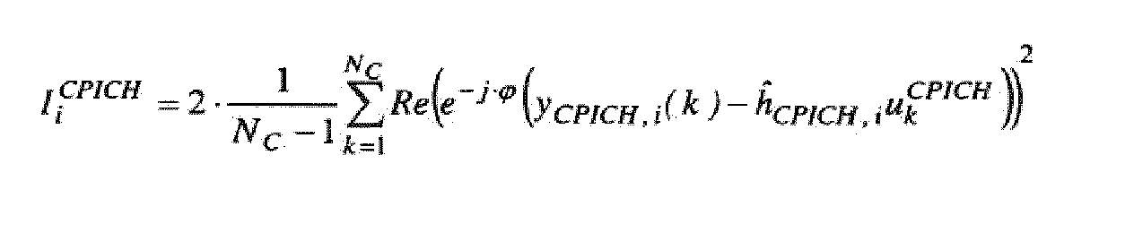
et
où Ii DPCH est une estimation d'un niveau d'interférence sur un premier canal DPCH pour une prise de récepteur i, Ii CPICH est une estimation d'un niveau d'interférence sur un second canal CPICH pour la prise i, k est un index temporel, SFC est un facteur d'étalement pour le second canal, SFD est un facteur d'étalement pour le premier canal, NC est un nombre de symboles par intervalle sur le second canal, ϕ est un angle de ĥCPICH,i, yCPICH,i (k) est un symbole pilote de désétalement du second canal à l'instant k pour la prise i, ĥCPICH,i est une estimation de canal du second canal pour la prise i et
- Procédé selon la revendication 1, dans lequel le signal reçu subit une annulation de rotation en estimant (402) une erreur de fréquence résiduelle, et les symboles d'annulation de rotation (404) dans le signal reçu avec un déphasagecorrespondant pour chaque symbole, les déphasages correspondants étant donnés par:

où ỹCPICH,i (k) sont les symboles ayant subi une annulation de rotation d'un canal CPICH, k est un index, fe est l'erreur de fréquence résiduelle, NC est un nombre de symboles par intervalle sur le canal, et RC est un débit de symboles sur le canal, et en utilisant les symboles ayant subi une annulation de rotation ỹCPICH,i (k) pour estimer le niveau d'interférence. - Procédé selon la revendication 1, dans lequel le récepteur fonctionne dans un système de communication sans fil à accès multiple par répartition de code large bande.
- Dispositif d'estimation d'un niveau d'interférence d'un signal reçu dans un récepteur (200), comprenant:un détecteur (208,210) configuré pour détecter un niveau d'interférence du signal reçu ; etun processeur (212) configuré pour déterminer si le niveau d'interférence détecté est bas ; caractérisé en ce que le processeur est en outre configuré pour, si le niveau d'interférence détecté est bas, estimer le niveau d'interférence par au moins une des étapes suivantes: estimer dans seulement une direction radiale ou annuler la rotation du signal reçu avant d'estimer le niveau d'interférence.
- Dispositif selon la revendication 9, dans lequel le détecteur (208,210) détecte le niveau d'interférence en estimant une qualité du signal reçu et le processeur (212) détermine si la qualité a franchi un seuil prédéterminé.
- Dispositif selon la revendication 10, dans lequel la qualité est un rapport de l'énergie chip sur l'énergie d'interférence.
- Dispositif selon la revendication 11, dans lequel le qualité est une puissance de code de signal reçu divisée par un indicateur d'intensité de signal reçue.
- Dispositif selon la revendication 9, dans lequel la direction radiale est parallèle à un axe de coordonnée réel.
- Dispositif selon la revendication 13, dans lequel le processeur (212) est configuré pour estimer le niveau d'interférence dans seulement une direction radiale selon

et
où Ii DPCH est une estimation d'un niveau d'interférence sur un premier canal DPCH pour une prise de récepteur i, Ii CPICH est une estimation d'un niveau d'interférence sur un second canal CPICH pour la prise i, k est un index temporel, SFC est un facteur d'étalement pour le second canal, SFD est un facteur d'étalement pour le premier canal, NC est un nombre de symboles par intervalle sur le second canal, ϕ est un angle de ĥCPICH,i yCPICH,i (k) est un symbole pilote de désétalement du second canal à l'instant k pour la prise i, ĥCPICH,i est une estimation de canal du second canal pour la prise i et uk CPICH est un symbole pilote du second canal à l'instant k. - Dispositif selon la revendication 9, dans lequel le processeur (212) est configuré pour annuler la rotation du signal reçu en estimant une erreur de fréquence résiduelle, et les symboles d'annulation de rotation (404) dans le signal reçu avec un déphasagecorrespondant pour chaque symbole, les déphasages correspondants étant donnés par:

où ỹCPICH,i (k) sont les symboles ayant subi une annulation de rotation d'un canal CPICH, k est un index, fe est l'erreur de fréquence résiduelle, NC est un nombre de symboles par intervalle sur le canal, et RC est un débit de symboles sur le canal, et en utilisant les symboles ayant subi une annulation de rotation ỹCPICH,i (k) pour estimer le niveau d'interférence. - Dispositif selon la revendication 9, dans lequel le récepteur (200) fonctionne dans un système de communication sans fil à accès multiple par répartition de code large bande.
- Support de mémorisation lisible par ordinateur contenant un programme informatique pour estimer un niveau d'interférence d'un signal reçu dans un récepteur, dans lequel le programme informatique effectue les étapes consistant à:détecter (302) un niveau d'interférence du signal reçu ;déterminer (304) si le niveau d'interférence détecté est bas ; etcaractérisé en ce que le programme informatique effectue en outre, si le niveau d'interférence détecté est bas, l'estimation (308) du niveau d'interférence par au moins par au moins une des étapes suivantes: estimer dans seulement une direction radiale ou annuler la rotation du signal reçu avant d'estimer le niveau d'interférence.
- Support selon la revendication 17, dans lequel le niveau d'interférence est détecté en estimant une qualité du signal reçu et déterminer si le niveau d'interférence détecté est bas inclut de déterminer si la qualité a franchi un seuil prédéterminé.
- Support selon la revendication 17, dans lequel le niveau d'interférence dans seulement une direction radiale selon

et
où Ii DPCH est une estimation d'un niveau d'interférence sur un premier canal DPCH pour une prise de récepteur i, Ii CPICH est une estimation d'un niveau d'interférence sur un second canal CPICH pour la prise i, k est un index temporel, SFC est un facteur d'étalement pour le second canal, SFD est un facteur d'étalement pour le premier canal, NC est un nombre de symboles par intervalle sur le second canal, ϕ est un angle de ĥCPICH,i, yCPICH,i (k) est un symbole pilote de désétalement du second canal à l'instant k pour la prise i, ĥCPICH,i est une estimation de canal du second canal pour la prise i et uk CPICH est un symbole pilote du second canal à l'instant k. - Support selon la revendication 17, dans lequel le signal reçu subit une annulation de rotation en estimant (402) une erreur de fréquence résiduelle, et en annulant la rotation (404) des symboles dans le signal reçu avec un déphasage correspondant pour chaque symbole, les déphasages correspondants étant donnés par:

où ỹCPICH,i (k) sont les symboles ayant subi une annulation de rotation d'un canal CPICH, k est un index, fe est l'erreur de fréquence résiduelle, NC est un nombre de symboles par intervalle sur le canal, et RC est un débit de symboles sur le canal, et en utilisant les symboles ayant subi une annulation de rotation ỹCPICH,i (k) pour estimer le niveau d'interférence.
Applications Claiming Priority (3)
| Application Number | Priority Date | Filing Date | Title |
|---|---|---|---|
| US64894005P | 2005-02-01 | 2005-02-01 | |
| US11/177,532 US7555074B2 (en) | 2005-02-01 | 2005-07-08 | Interference estimation in the presence of frequency errors |
| PCT/EP2006/000916 WO2006082055A1 (fr) | 2005-02-01 | 2006-01-27 | Evaluation du parasitage en presence d'erreurs de frequence |
Publications (2)
| Publication Number | Publication Date |
|---|---|
| EP1844561A1 EP1844561A1 (fr) | 2007-10-17 |
| EP1844561B1 true EP1844561B1 (fr) | 2012-06-13 |
Family
ID=36218804
Family Applications (1)
| Application Number | Title | Priority Date | Filing Date |
|---|---|---|---|
| EP06706586A Not-in-force EP1844561B1 (fr) | 2005-02-01 | 2006-01-27 | Estimation d'interference en presence d'erreurs de frequence |
Country Status (5)
| Country | Link |
|---|---|
| US (1) | US7555074B2 (fr) |
| EP (1) | EP1844561B1 (fr) |
| JP (1) | JP4870687B2 (fr) |
| KR (1) | KR20070104901A (fr) |
| WO (1) | WO2006082055A1 (fr) |
Families Citing this family (10)
| Publication number | Priority date | Publication date | Assignee | Title |
|---|---|---|---|---|
| US20050272373A1 (en) * | 2003-06-04 | 2005-12-08 | Matsushita Electric Industrial Co., Ltd | Sir measurement device and sir measurement method |
| US7609791B2 (en) * | 2006-04-21 | 2009-10-27 | Telefonaktiebolaget L M Ericsson (Publ) | Iterative decoding with intentional SNR/SIR reduction |
| US8184675B2 (en) * | 2006-07-12 | 2012-05-22 | Telefonaktiebolaget L M Ericsson (Publ) | Residual frequency offset exploitation |
| US7688920B2 (en) * | 2006-07-12 | 2010-03-30 | Telefonaktiebolaget L M Ericsson (Publ) | AFC wrap-around detection |
| JP4543289B2 (ja) * | 2008-01-24 | 2010-09-15 | Necアクセステクニカ株式会社 | ノイズレベル測定方法および装置 |
| WO2010003105A1 (fr) * | 2008-07-02 | 2010-01-07 | Sirius Xm Radio Inc. | Procédé permettant de minimiser des interférences dans une réception sdards patrimoniale en faisant varier la modulation de recouvrement en fonction d'une position de satellite |
| US8520782B2 (en) | 2010-12-17 | 2013-08-27 | Telefonaktiebolaget L M Ericsson (Publ) | Receiver power reduction methods and apparatus |
| EP2536031A1 (fr) | 2011-06-15 | 2012-12-19 | TELEFONAKTIEBOLAGET LM ERICSSON (publ) | Procédé et récepteur radio permettant la détection de la distorsion harmonique |
| EP2725727B1 (fr) * | 2011-08-12 | 2018-02-21 | Telefonaktiebolaget LM Ericsson (publ) | Détermination de l'indice de qualité de canal |
| US9276629B2 (en) * | 2011-11-17 | 2016-03-01 | Intel Deutschland Gmbh | Rake receiver circuit and method for operating a rake receiver circuit |
Family Cites Families (27)
| Publication number | Priority date | Publication date | Assignee | Title |
|---|---|---|---|---|
| US5140615A (en) * | 1990-06-12 | 1992-08-18 | Motorola, Inc. | Maximal ratio diversity combining technique |
| US5305349A (en) | 1993-04-29 | 1994-04-19 | Ericsson Ge Mobile Communications Inc. | Quantized coherent rake receiver |
| US5659583A (en) | 1995-06-02 | 1997-08-19 | Hitachi America, Ltd. | Tone canceller for QAM demodulator |
| US5933768A (en) | 1997-02-28 | 1999-08-03 | Telefonaktiebolaget L/M Ericsson | Receiver apparatus, and associated method, for receiving a receive signal transmitted upon a channel susceptible to interference |
| US6754251B1 (en) | 1998-03-09 | 2004-06-22 | Texas Instruments Incorporated | Spread-spectrum telephony with accelerated code acquisition |
| US6363104B1 (en) | 1998-10-02 | 2002-03-26 | Ericsson Inc. | Method and apparatus for interference cancellation in a rake receiver |
| US6801565B1 (en) | 1999-06-25 | 2004-10-05 | Ericsson Inc. | Multi-stage rake combining methods and apparatus |
| US6922434B2 (en) | 1999-10-19 | 2005-07-26 | Ericsson Inc. | Apparatus and methods for finger delay selection in RAKE receivers |
| JP2001186082A (ja) * | 1999-12-24 | 2001-07-06 | Matsushita Electric Ind Co Ltd | Cdma移動通信システム及び方法 |
| US6606363B1 (en) | 1999-12-28 | 2003-08-12 | Telefonaktiebolaget Lm Ericsson (Publ) | Method and apparatus for estimating a frequency offset by combining pilot symbols and data symbols |
| US6621857B1 (en) * | 1999-12-31 | 2003-09-16 | Thomson Licensing S.A. | Carrier tracking loop for direct sequence spread spectrum systems |
| JP3507409B2 (ja) * | 2000-06-09 | 2004-03-15 | 日本電信電話株式会社 | ディジタル無線通信用送信回路 |
| JP3439724B2 (ja) * | 2000-06-29 | 2003-08-25 | 日本電信電話株式会社 | ディジタル無線通信システム用送受信回路 |
| JP2002043978A (ja) * | 2000-07-28 | 2002-02-08 | Hitachi Kokusai Electric Inc | Cdma受信機 |
| US7443826B1 (en) | 2000-10-04 | 2008-10-28 | Telefonaktiebolaget L M Ericsson (Publ) | Method and apparatus for automatic frequency control in a CDMA receiver |
| US7346126B2 (en) * | 2001-11-28 | 2008-03-18 | Telefonaktiebolaget L M Ericsson (Publ) | Method and apparatus for channel estimation using plural channels |
| US7149258B2 (en) * | 2001-11-28 | 2006-12-12 | Telefonaktiebolaget L M Ericsson (Publ) | Method and apparatus for estimation of phase offset between communication channels |
| JP4057342B2 (ja) * | 2002-05-24 | 2008-03-05 | 株式会社日立国際電気 | 受信レベル測定回路 |
| JP4084058B2 (ja) * | 2002-03-07 | 2008-04-30 | 株式会社日立国際電気 | 受信レベル測定回路 |
| US6794858B2 (en) | 2002-03-07 | 2004-09-21 | Hitachi Kokusai Electric Inc. | Receiving level measuring circuit |
| US6741587B2 (en) * | 2002-04-02 | 2004-05-25 | Nokia Corporation | Inter-frequency measurements with MIMO terminals |
| US7110765B2 (en) * | 2002-08-27 | 2006-09-19 | Qualcomm Incorporated | Limiting cell reselection based on pilot power |
| US6879813B2 (en) | 2003-01-30 | 2005-04-12 | Interdigital Technology Corporation | Link-quality estimation method and components for multi-user wireless communication systems |
| CA2427755A1 (fr) * | 2003-05-05 | 2004-11-05 | Macdon Industries Ltd. | Systeme de formation d'andains pour bec cueilleur de recolte |
| AU2004307449C1 (en) * | 2003-10-24 | 2009-04-30 | Qualcomm Incorporated | Frequency division multiplexing of multiple data streams in a wireless multi-carrier communication system |
| US7822155B2 (en) | 2003-11-04 | 2010-10-26 | Telefonaktiebolaget L M Ericsson (Publ) | Interference estimation in CDMA systems using alternative scrambling codes |
| US7433433B2 (en) | 2003-11-13 | 2008-10-07 | Telefonaktiebolaget L M Ericsson (Publ) | Channel estimation by adaptive interpolation |
-
2005
- 2005-07-08 US US11/177,532 patent/US7555074B2/en active Active
-
2006
- 2006-01-27 WO PCT/EP2006/000916 patent/WO2006082055A1/fr active Application Filing
- 2006-01-27 JP JP2007552602A patent/JP4870687B2/ja not_active Expired - Fee Related
- 2006-01-27 KR KR1020077017822A patent/KR20070104901A/ko not_active Application Discontinuation
- 2006-01-27 EP EP06706586A patent/EP1844561B1/fr not_active Not-in-force
Also Published As
| Publication number | Publication date |
|---|---|
| KR20070104901A (ko) | 2007-10-29 |
| WO2006082055A1 (fr) | 2006-08-10 |
| US7555074B2 (en) | 2009-06-30 |
| JP2008529372A (ja) | 2008-07-31 |
| EP1844561A1 (fr) | 2007-10-17 |
| JP4870687B2 (ja) | 2012-02-08 |
| US20060171449A1 (en) | 2006-08-03 |
Similar Documents
| Publication | Publication Date | Title |
|---|---|---|
| EP1844561B1 (fr) | Estimation d'interference en presence d'erreurs de frequence | |
| JP4444961B2 (ja) | 伝送チャネルのチャネル評価の決定 | |
| EP1955565B1 (fr) | Selection de cellule dans des systeme de communication a acces par paquets de liaisons descendantes haute vitesse | |
| TWI454077B (zh) | 一種處理信號的方法和系統 | |
| KR101146859B1 (ko) | 셀 선택을 위한 방법 및 장치 | |
| JP4616336B2 (ja) | ソフトハンドオーバー中の同期検出および出力制御の方法とその装置 | |
| EP2218198A2 (fr) | Réglage de puissance pour émetteur-récepteur radio utilisant une annulation de brouillage | |
| JP2004519152A (ja) | 無線パケットデータ通信システムにおける順方向リンクの閉ループの電力制御設定点を判断するための方法および装置 | |
| US9369970B2 (en) | Method and device for denoising in channel estimation, and corresponding computer program and computer readable storage medium | |
| EP2016686B1 (fr) | Decodage iteratif avec reduction intentionnelle de snr/sir | |
| EP1480350B1 (fr) | Détermination d'une estimation de canal d'un canal de transmission | |
| WO2006088259A1 (fr) | Mesure de la qualite du signal | |
| US8520782B2 (en) | Receiver power reduction methods and apparatus | |
| KR101643952B1 (ko) | 이동 통신 시스템에서 채널 추정 장치 및 방법 | |
| US8009777B2 (en) | Processing data in a digital communications system | |
| EP1065802B1 (fr) | Procédé et dispositif de commande de la puissance de transmission en mésurant l' Eb/No de la combinaison de signaux pondérés | |
| JP4418289B2 (ja) | ジオメトリ測定方法、無線受信装置及び移動局装置 | |
| CN101112025A (zh) | 存在频率误差时的干涉估计 |
Legal Events
| Date | Code | Title | Description |
|---|---|---|---|
| PUAI | Public reference made under article 153(3) epc to a published international application that has entered the european phase |
Free format text: ORIGINAL CODE: 0009012 |
|
| 17P | Request for examination filed |
Effective date: 20070705 |
|
| AK | Designated contracting states |
Kind code of ref document: A1 Designated state(s): AT BE BG CH CY CZ DE DK EE ES FI FR GB GR HU IE IS IT LI LT LU LV MC NL PL PT RO SE SI SK TR |
|
| DAX | Request for extension of the european patent (deleted) | ||
| 17Q | First examination report despatched |
Effective date: 20100112 |
|
| GRAP | Despatch of communication of intention to grant a patent |
Free format text: ORIGINAL CODE: EPIDOSNIGR1 |
|
| GRAS | Grant fee paid |
Free format text: ORIGINAL CODE: EPIDOSNIGR3 |
|
| GRAA | (expected) grant |
Free format text: ORIGINAL CODE: 0009210 |
|
| AK | Designated contracting states |
Kind code of ref document: B1 Designated state(s): AT BE BG CH CY CZ DE DK EE ES FI FR GB GR HU IE IS IT LI LT LU LV MC NL PL PT RO SE SI SK TR |
|
| REG | Reference to a national code |
Ref country code: GB Ref legal event code: FG4D |
|
| REG | Reference to a national code |
Ref country code: CH Ref legal event code: EP Ref country code: AT Ref legal event code: REF Ref document number: 562389 Country of ref document: AT Kind code of ref document: T Effective date: 20120615 |
|
| REG | Reference to a national code |
Ref country code: IE Ref legal event code: FG4D |
|
| REG | Reference to a national code |
Ref country code: DE Ref legal event code: R096 Ref document number: 602006030091 Country of ref document: DE Effective date: 20120809 |
|
| REG | Reference to a national code |
Ref country code: NL Ref legal event code: VDEP Effective date: 20120613 |
|
| PG25 | Lapsed in a contracting state [announced via postgrant information from national office to epo] |
Ref country code: LT Free format text: LAPSE BECAUSE OF FAILURE TO SUBMIT A TRANSLATION OF THE DESCRIPTION OR TO PAY THE FEE WITHIN THE PRESCRIBED TIME-LIMIT Effective date: 20120613 Ref country code: SE Free format text: LAPSE BECAUSE OF FAILURE TO SUBMIT A TRANSLATION OF THE DESCRIPTION OR TO PAY THE FEE WITHIN THE PRESCRIBED TIME-LIMIT Effective date: 20120613 Ref country code: CY Free format text: LAPSE BECAUSE OF FAILURE TO SUBMIT A TRANSLATION OF THE DESCRIPTION OR TO PAY THE FEE WITHIN THE PRESCRIBED TIME-LIMIT Effective date: 20120613 Ref country code: FI Free format text: LAPSE BECAUSE OF FAILURE TO SUBMIT A TRANSLATION OF THE DESCRIPTION OR TO PAY THE FEE WITHIN THE PRESCRIBED TIME-LIMIT Effective date: 20120613 |
|
| REG | Reference to a national code |
Ref country code: AT Ref legal event code: MK05 Ref document number: 562389 Country of ref document: AT Kind code of ref document: T Effective date: 20120613 |
|
| REG | Reference to a national code |
Ref country code: LT Ref legal event code: MG4D Effective date: 20120613 |
|
| PG25 | Lapsed in a contracting state [announced via postgrant information from national office to epo] |
Ref country code: SI Free format text: LAPSE BECAUSE OF FAILURE TO SUBMIT A TRANSLATION OF THE DESCRIPTION OR TO PAY THE FEE WITHIN THE PRESCRIBED TIME-LIMIT Effective date: 20120613 Ref country code: LV Free format text: LAPSE BECAUSE OF FAILURE TO SUBMIT A TRANSLATION OF THE DESCRIPTION OR TO PAY THE FEE WITHIN THE PRESCRIBED TIME-LIMIT Effective date: 20120613 Ref country code: GR Free format text: LAPSE BECAUSE OF FAILURE TO SUBMIT A TRANSLATION OF THE DESCRIPTION OR TO PAY THE FEE WITHIN THE PRESCRIBED TIME-LIMIT Effective date: 20120914 |
|
| PG25 | Lapsed in a contracting state [announced via postgrant information from national office to epo] |
Ref country code: SK Free format text: LAPSE BECAUSE OF FAILURE TO SUBMIT A TRANSLATION OF THE DESCRIPTION OR TO PAY THE FEE WITHIN THE PRESCRIBED TIME-LIMIT Effective date: 20120613 Ref country code: EE Free format text: LAPSE BECAUSE OF FAILURE TO SUBMIT A TRANSLATION OF THE DESCRIPTION OR TO PAY THE FEE WITHIN THE PRESCRIBED TIME-LIMIT Effective date: 20120613 Ref country code: IS Free format text: LAPSE BECAUSE OF FAILURE TO SUBMIT A TRANSLATION OF THE DESCRIPTION OR TO PAY THE FEE WITHIN THE PRESCRIBED TIME-LIMIT Effective date: 20121013 Ref country code: RO Free format text: LAPSE BECAUSE OF FAILURE TO SUBMIT A TRANSLATION OF THE DESCRIPTION OR TO PAY THE FEE WITHIN THE PRESCRIBED TIME-LIMIT Effective date: 20120613 Ref country code: BE Free format text: LAPSE BECAUSE OF FAILURE TO SUBMIT A TRANSLATION OF THE DESCRIPTION OR TO PAY THE FEE WITHIN THE PRESCRIBED TIME-LIMIT Effective date: 20120613 Ref country code: CZ Free format text: LAPSE BECAUSE OF FAILURE TO SUBMIT A TRANSLATION OF THE DESCRIPTION OR TO PAY THE FEE WITHIN THE PRESCRIBED TIME-LIMIT Effective date: 20120613 Ref country code: AT Free format text: LAPSE BECAUSE OF FAILURE TO SUBMIT A TRANSLATION OF THE DESCRIPTION OR TO PAY THE FEE WITHIN THE PRESCRIBED TIME-LIMIT Effective date: 20120613 |
|
| PG25 | Lapsed in a contracting state [announced via postgrant information from national office to epo] |
Ref country code: PT Free format text: LAPSE BECAUSE OF FAILURE TO SUBMIT A TRANSLATION OF THE DESCRIPTION OR TO PAY THE FEE WITHIN THE PRESCRIBED TIME-LIMIT Effective date: 20121015 Ref country code: PL Free format text: LAPSE BECAUSE OF FAILURE TO SUBMIT A TRANSLATION OF THE DESCRIPTION OR TO PAY THE FEE WITHIN THE PRESCRIBED TIME-LIMIT Effective date: 20120613 Ref country code: IT Free format text: LAPSE BECAUSE OF FAILURE TO SUBMIT A TRANSLATION OF THE DESCRIPTION OR TO PAY THE FEE WITHIN THE PRESCRIBED TIME-LIMIT Effective date: 20120613 |
|
| PG25 | Lapsed in a contracting state [announced via postgrant information from national office to epo] |
Ref country code: NL Free format text: LAPSE BECAUSE OF FAILURE TO SUBMIT A TRANSLATION OF THE DESCRIPTION OR TO PAY THE FEE WITHIN THE PRESCRIBED TIME-LIMIT Effective date: 20120613 |
|
| PLBE | No opposition filed within time limit |
Free format text: ORIGINAL CODE: 0009261 |
|
| STAA | Information on the status of an ep patent application or granted ep patent |
Free format text: STATUS: NO OPPOSITION FILED WITHIN TIME LIMIT |
|
| PG25 | Lapsed in a contracting state [announced via postgrant information from national office to epo] |
Ref country code: ES Free format text: LAPSE BECAUSE OF FAILURE TO SUBMIT A TRANSLATION OF THE DESCRIPTION OR TO PAY THE FEE WITHIN THE PRESCRIBED TIME-LIMIT Effective date: 20120924 Ref country code: DK Free format text: LAPSE BECAUSE OF FAILURE TO SUBMIT A TRANSLATION OF THE DESCRIPTION OR TO PAY THE FEE WITHIN THE PRESCRIBED TIME-LIMIT Effective date: 20120613 |
|
| 26N | No opposition filed |
Effective date: 20130314 |
|
| REG | Reference to a national code |
Ref country code: DE Ref legal event code: R097 Ref document number: 602006030091 Country of ref document: DE Effective date: 20130314 |
|
| PG25 | Lapsed in a contracting state [announced via postgrant information from national office to epo] |
Ref country code: BG Free format text: LAPSE BECAUSE OF FAILURE TO SUBMIT A TRANSLATION OF THE DESCRIPTION OR TO PAY THE FEE WITHIN THE PRESCRIBED TIME-LIMIT Effective date: 20120913 |
|
| PG25 | Lapsed in a contracting state [announced via postgrant information from national office to epo] |
Ref country code: MC Free format text: LAPSE BECAUSE OF NON-PAYMENT OF DUE FEES Effective date: 20130131 |
|
| REG | Reference to a national code |
Ref country code: CH Ref legal event code: PL |
|
| REG | Reference to a national code |
Ref country code: IE Ref legal event code: MM4A |
|
| REG | Reference to a national code |
Ref country code: FR Ref legal event code: ST Effective date: 20130930 |
|
| PG25 | Lapsed in a contracting state [announced via postgrant information from national office to epo] |
Ref country code: CH Free format text: LAPSE BECAUSE OF NON-PAYMENT OF DUE FEES Effective date: 20130131 Ref country code: LI Free format text: LAPSE BECAUSE OF NON-PAYMENT OF DUE FEES Effective date: 20130131 Ref country code: DE Free format text: LAPSE BECAUSE OF NON-PAYMENT OF DUE FEES Effective date: 20130801 |
|
| REG | Reference to a national code |
Ref country code: DE Ref legal event code: R119 Ref document number: 602006030091 Country of ref document: DE Effective date: 20130801 |
|
| PG25 | Lapsed in a contracting state [announced via postgrant information from national office to epo] |
Ref country code: FR Free format text: LAPSE BECAUSE OF NON-PAYMENT OF DUE FEES Effective date: 20130131 |
|
| PG25 | Lapsed in a contracting state [announced via postgrant information from national office to epo] |
Ref country code: IE Free format text: LAPSE BECAUSE OF NON-PAYMENT OF DUE FEES Effective date: 20130127 |
|
| PG25 | Lapsed in a contracting state [announced via postgrant information from national office to epo] |
Ref country code: TR Free format text: LAPSE BECAUSE OF FAILURE TO SUBMIT A TRANSLATION OF THE DESCRIPTION OR TO PAY THE FEE WITHIN THE PRESCRIBED TIME-LIMIT Effective date: 20120613 |
|
| PG25 | Lapsed in a contracting state [announced via postgrant information from national office to epo] |
Ref country code: LU Free format text: LAPSE BECAUSE OF NON-PAYMENT OF DUE FEES Effective date: 20130127 Ref country code: HU Free format text: LAPSE BECAUSE OF FAILURE TO SUBMIT A TRANSLATION OF THE DESCRIPTION OR TO PAY THE FEE WITHIN THE PRESCRIBED TIME-LIMIT; INVALID AB INITIO Effective date: 20060127 |
|
| PGFP | Annual fee paid to national office [announced via postgrant information from national office to epo] |
Ref country code: GB Payment date: 20180129 Year of fee payment: 13 |
|
| GBPC | Gb: european patent ceased through non-payment of renewal fee |
Effective date: 20190127 |
|
| PG25 | Lapsed in a contracting state [announced via postgrant information from national office to epo] |
Ref country code: GB Free format text: LAPSE BECAUSE OF NON-PAYMENT OF DUE FEES Effective date: 20190127 |