EP1843055A1 - Palier de roulement doté d'un capteur - Google Patents
Palier de roulement doté d'un capteur Download PDFInfo
- Publication number
- EP1843055A1 EP1843055A1 EP20070006804 EP07006804A EP1843055A1 EP 1843055 A1 EP1843055 A1 EP 1843055A1 EP 20070006804 EP20070006804 EP 20070006804 EP 07006804 A EP07006804 A EP 07006804A EP 1843055 A1 EP1843055 A1 EP 1843055A1
- Authority
- EP
- European Patent Office
- Prior art keywords
- rolling
- sensor strip
- rolling bearing
- sensor
- outer ring
- Prior art date
- Legal status (The legal status is an assumption and is not a legal conclusion. Google has not performed a legal analysis and makes no representation as to the accuracy of the status listed.)
- Granted
Links
- 238000005096 rolling process Methods 0.000 claims abstract description 66
- HFGPZNIAWCZYJU-UHFFFAOYSA-N lead zirconate titanate Chemical compound [O-2].[O-2].[O-2].[O-2].[O-2].[Ti+4].[Zr+4].[Pb+2] HFGPZNIAWCZYJU-UHFFFAOYSA-N 0.000 claims abstract description 5
- 239000000835 fiber Substances 0.000 claims abstract description 4
- 229910052451 lead zirconate titanate Inorganic materials 0.000 claims description 4
- 230000000694 effects Effects 0.000 claims description 3
- 230000000737 periodic effect Effects 0.000 description 10
- 230000002093 peripheral effect Effects 0.000 description 9
- 238000012935 Averaging Methods 0.000 description 8
- 230000005540 biological transmission Effects 0.000 description 3
- 238000000034 method Methods 0.000 description 3
- 238000011156 evaluation Methods 0.000 description 2
- 230000010354 integration Effects 0.000 description 2
- 238000007789 sealing Methods 0.000 description 2
- 230000003111 delayed effect Effects 0.000 description 1
- 230000001419 dependent effect Effects 0.000 description 1
- 238000001514 detection method Methods 0.000 description 1
- 238000011161 development Methods 0.000 description 1
- 230000018109 developmental process Effects 0.000 description 1
- 239000003822 epoxy resin Substances 0.000 description 1
- 238000005259 measurement Methods 0.000 description 1
- 229920000647 polyepoxide Polymers 0.000 description 1
- 238000012545 processing Methods 0.000 description 1
- 230000005855 radiation Effects 0.000 description 1
- 239000004065 semiconductor Substances 0.000 description 1
- 238000007493 shaping process Methods 0.000 description 1
- 239000010409 thin film Substances 0.000 description 1
Images
Classifications
-
- G—PHYSICS
- G01—MEASURING; TESTING
- G01L—MEASURING FORCE, STRESS, TORQUE, WORK, MECHANICAL POWER, MECHANICAL EFFICIENCY, OR FLUID PRESSURE
- G01L5/00—Apparatus for, or methods of, measuring force, work, mechanical power, or torque, specially adapted for specific purposes
- G01L5/0009—Force sensors associated with a bearing
- G01L5/0019—Force sensors associated with a bearing by using strain gages, piezoelectric, piezo-resistive or other ohmic-resistance based sensors
-
- B—PERFORMING OPERATIONS; TRANSPORTING
- B60—VEHICLES IN GENERAL
- B60B—VEHICLE WHEELS; CASTORS; AXLES FOR WHEELS OR CASTORS; INCREASING WHEEL ADHESION
- B60B27/00—Hubs
- B60B27/0005—Hubs with ball bearings
-
- B—PERFORMING OPERATIONS; TRANSPORTING
- B60—VEHICLES IN GENERAL
- B60B—VEHICLE WHEELS; CASTORS; AXLES FOR WHEELS OR CASTORS; INCREASING WHEEL ADHESION
- B60B27/00—Hubs
- B60B27/0078—Hubs characterised by the fixation of bearings
- B60B27/0084—Hubs characterised by the fixation of bearings caulking to fix inner race
-
- F—MECHANICAL ENGINEERING; LIGHTING; HEATING; WEAPONS; BLASTING
- F16—ENGINEERING ELEMENTS AND UNITS; GENERAL MEASURES FOR PRODUCING AND MAINTAINING EFFECTIVE FUNCTIONING OF MACHINES OR INSTALLATIONS; THERMAL INSULATION IN GENERAL
- F16C—SHAFTS; FLEXIBLE SHAFTS; ELEMENTS OR CRANKSHAFT MECHANISMS; ROTARY BODIES OTHER THAN GEARING ELEMENTS; BEARINGS
- F16C19/00—Bearings with rolling contact, for exclusively rotary movement
- F16C19/02—Bearings with rolling contact, for exclusively rotary movement with bearing balls essentially of the same size in one or more circular rows
- F16C19/14—Bearings with rolling contact, for exclusively rotary movement with bearing balls essentially of the same size in one or more circular rows for both radial and axial load
- F16C19/18—Bearings with rolling contact, for exclusively rotary movement with bearing balls essentially of the same size in one or more circular rows for both radial and axial load with two or more rows of balls
- F16C19/181—Bearings with rolling contact, for exclusively rotary movement with bearing balls essentially of the same size in one or more circular rows for both radial and axial load with two or more rows of balls with angular contact
- F16C19/183—Bearings with rolling contact, for exclusively rotary movement with bearing balls essentially of the same size in one or more circular rows for both radial and axial load with two or more rows of balls with angular contact with two rows at opposite angles
- F16C19/184—Bearings with rolling contact, for exclusively rotary movement with bearing balls essentially of the same size in one or more circular rows for both radial and axial load with two or more rows of balls with angular contact with two rows at opposite angles in O-arrangement
- F16C19/185—Bearings with rolling contact, for exclusively rotary movement with bearing balls essentially of the same size in one or more circular rows for both radial and axial load with two or more rows of balls with angular contact with two rows at opposite angles in O-arrangement with two raceways provided integrally on a part other than a race ring, e.g. a shaft or housing
-
- F—MECHANICAL ENGINEERING; LIGHTING; HEATING; WEAPONS; BLASTING
- F16—ENGINEERING ELEMENTS AND UNITS; GENERAL MEASURES FOR PRODUCING AND MAINTAINING EFFECTIVE FUNCTIONING OF MACHINES OR INSTALLATIONS; THERMAL INSULATION IN GENERAL
- F16C—SHAFTS; FLEXIBLE SHAFTS; ELEMENTS OR CRANKSHAFT MECHANISMS; ROTARY BODIES OTHER THAN GEARING ELEMENTS; BEARINGS
- F16C19/00—Bearings with rolling contact, for exclusively rotary movement
- F16C19/52—Bearings with rolling contact, for exclusively rotary movement with devices affected by abnormal or undesired conditions
- F16C19/522—Bearings with rolling contact, for exclusively rotary movement with devices affected by abnormal or undesired conditions related to load on the bearing, e.g. bearings with load sensors or means to protect the bearing against overload
-
- F—MECHANICAL ENGINEERING; LIGHTING; HEATING; WEAPONS; BLASTING
- F16—ENGINEERING ELEMENTS AND UNITS; GENERAL MEASURES FOR PRODUCING AND MAINTAINING EFFECTIVE FUNCTIONING OF MACHINES OR INSTALLATIONS; THERMAL INSULATION IN GENERAL
- F16C—SHAFTS; FLEXIBLE SHAFTS; ELEMENTS OR CRANKSHAFT MECHANISMS; ROTARY BODIES OTHER THAN GEARING ELEMENTS; BEARINGS
- F16C33/00—Parts of bearings; Special methods for making bearings or parts thereof
- F16C33/30—Parts of ball or roller bearings
- F16C33/58—Raceways; Race rings
- F16C33/583—Details of specific parts of races
- F16C33/586—Details of specific parts of races outside the space between the races, e.g. end faces or bore of inner ring
-
- F—MECHANICAL ENGINEERING; LIGHTING; HEATING; WEAPONS; BLASTING
- F16—ENGINEERING ELEMENTS AND UNITS; GENERAL MEASURES FOR PRODUCING AND MAINTAINING EFFECTIVE FUNCTIONING OF MACHINES OR INSTALLATIONS; THERMAL INSULATION IN GENERAL
- F16C—SHAFTS; FLEXIBLE SHAFTS; ELEMENTS OR CRANKSHAFT MECHANISMS; ROTARY BODIES OTHER THAN GEARING ELEMENTS; BEARINGS
- F16C2326/00—Articles relating to transporting
- F16C2326/01—Parts of vehicles in general
- F16C2326/02—Wheel hubs or castors
Definitions
- the present invention relates to a rolling bearing with a sensor.
- the invention will be described with reference to a rolling bearing in a motor vehicle, but it should be noted that the invention is also applicable to other devices in which rolling bearings are used.
- the electronic control systems for driving in the vehicle increasingly require more information about the current driving situation.
- the current forces and force directions such as wheel contact forces acting on the individual tires, should also be used to control the driving operation.
- various attempts at solution are known from the prior art.
- DMS strain gauges
- Metrologically interesting is the DC component from which the respective acting forces are determined.
- the prior art uses moving average filters with the window width of a signal period. It is also known to integrate the signal over the signal period to separate the DC component from the periodic signal.
- the present invention is therefore an object of the invention to provide a force and moments measuring rolling bearing available, which both at standstill and in all speed ranges in which the bearing can be operated, a speed-independent and qualitatively constant signal detection and evaluation and Edition possible.
- the evaluation procedure should be simplified and in particular the use of additional filters such as a sliding average filter and the like should be dispensed with.
- the signal acquisition should be simplified.
- the rolling bearing according to the invention has an outer ring and an inner ring and a plurality of arranged between the outer ring and the inner ring rolling elements.
- the rolling bearing has at least one sensor strip, which is arranged on a peripheral surface of at least one bearing ring.
- the sensor strip has a predetermined active length and this active length is determined taking into account the distance between two adjacent rolling elements.
- the sensor strip may be arranged on the peripheral surface, but it may also be provided on a housing part adjacent to the peripheral surface.
- the distance between two adjacent rolling elements can be directly on the one hand, the geometric distance of the centers of these two rolling elements. In addition, it is also possible to adjust the distance over the angle that the respective Include centers of the two rolling elements with respect to the bearing center point to determine.
- the active length of the sensor strip is understood to be the length over which the forces transmitted to the sensor strip are determined. In particular, this involves the measuring grid length of a strain gage or the area of strain transmission on the strain gage.
- the peripheral surface is preferably a circumferential surface facing away from the rolling bodies.
- the active length is an integer multiple of the distance projected to the remote circumferential surface of the adjacent rolling elements.
- an averaging of the measured signal is achieved by this special geometric shape.
- no periodic signal is output because the signal output from the sensor strip is independent of the exact position of the rolling elements with respect to the sensor strip.
- the moving averaging of the prior art in the time domain of Sensor strip signal replaced by a geometric averaging by the targeted shaping of the sensor strip. This geometric averaging does not produce a time offset.
- both the gage length of the gage and the strain gearing area on the strain gage correspond to the rolling element pitch projected on the opposite circumferential surface or an integer multiple thereof.
- the lateral surface of this outer ring would be decisive for the determination of the measuring grid length and the strain transmission of the DMS.
- the active length may also be, for example, slightly less or higher than the distance projected on the opposite circumferential surface.
- a small periodic component would also be output, which could at the same time be used as a measure of the rotational frequency of the rolling bodies.
- the projected distance is understood to mean a projection starting from the center of the rolling bearing.
- the projected surface may be a flat or curved surface.
- the active length of the projected on the opposite peripheral surface distance between two adjacent rolling elements is the special case that the integer multiple is the exact simple of the projected distance of the adjacent rolling elements.
- the sensor strip is arranged on a stationary bearing ring. This procedure is advantageous because, on the one hand, the measured signals can be transmitted more easily and, on the other hand, when evaluating the forces, the respective rotational position of a rotating ring need not be taken into account.
- the sensor strip is arranged on the outer ring of the bearing. This means that, as mentioned above, the measuring grid length of the sensor strip in this case corresponds to the rolling body distance projected onto the outer surface of the outer ring or an integral multiple thereof.
- a plurality of sensor strips is provided. These sensor strips are arranged on the respective stationary bearing ring at fixed predetermined positions. These positions are selected with regard to the forces to be measured, for example with regard to weight forces to be measured, braking forces to be measured or friction coefficients to be determined.
- the sensor strips are a DMS strip.
- These strain gauges or thin-film strain gauges can be used to determine the reaction forces (the change in tension) on the respectively fixed bearing ring of the wheel bearing. When driving without braking, the wheel contact forces can be determined directly from these loads.
- semiconductor DMS may also be used. These offer the advantage of small dimensions.
- PZT lead zirconate titanate
- the present invention is further directed to a vehicle, and more particularly to a motor vehicle having a rolling bearing of the type described above.
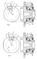
- Fig. 1 shows a side view of a rolling bearing according to the invention and a schematic plan view illustrating the length of the sensor strip as a function of the rolling element spacing.
- the reference numeral 2 refers to an outer ring of the bearing and the reference numeral 3 to an inner ring or on an inner ring half. Between the outer ring and the inner ring a plurality of rolling elements 5 is arranged in two rows.
- the reference numeral 7 refers to the rotating wheel flange.
- a sensor strip 4 is provided, which extends in the circumferential direction of the outer ring 2 and thus in a plane perpendicular to the plane of the figure.
- the reference numeral 11 denotes a sealing element and the reference numeral 12 a projection of the wheel flange 7 for the axial fixing of the inner ring halves third
- the outer periphery of the outer ring 2 is circular in this embodiment.
- the reference character Kw refers to the circular line of the rolling elements 5, d. H. the circle on which the centers or the axes of rotation of the rolling elements 5 are arranged.
- the reference symbol L denotes the active length of the sensor strip 4.
- the measuring grid length of the strain gauge corresponds to the rolling body distance d projected from the center point M on the lateral surface of the outer ring, or an integral multiple thereof.
- R is the radius of the peripheral surface of the outer ring
- n is the number of rolling elements 5 in a row.
- the active length depends here on the outer diameter of the outer ring 2.
- Fig. 2 shows another embodiment of the rolling bearing according to the invention.
- the essential difference lies in the configuration of the outer circumference of the outer ring 2.
- This has in the embodiment shown in FIG. 2 flattened areas 13, on which sensor strips are arranged.
- the length of the sensor strip running straight here could be determined, for example, for geometrical considerations with the aid of the radiation sets.
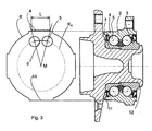
- Fig. 3 shows a further embodiment of the rolling bearing according to the invention.
- the sensor strip is arranged on a flattening 14 raised in relation to the circular shape of the outer ring.
- the strain gage is substantially rectilinear and its length may also result from geometrical considerations with the aid of the ray sets.
- the surface on which the strain gauge 4 is disposed may take other forms, but in any case it is crucial that the length of this strain gauge corresponds to the above-mentioned projection or a multiple thereof or adapted to it.
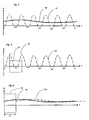
- Fig. 4 shows a comparison of the sensor signals.
- the reference numeral 17 refers to a recorded with a strain gauge according to the prior art signal.
- the signal has the above-mentioned periodic fluctuations caused by the passage of the rolling element arise at the strain gauge.
- the reference numeral 18 refers to a signal with a strain gauge according to the invention, which is adjusted by the periodic portion of the signal 17. In the case of the signal 17, this signal must be integrated over at least one signal period to determine the metrologically relevant DC component.
- the amplitude A is plotted against the time t.
- Fig. 5 shows such integration. More specifically, in Fig. 5, a time window 19 is shown indicating the minimum necessary window width for the moving averaging. The integration via this window gives the metrologically relevant value of the DC component.
- Fig. 6 shows an illustration of the time delay ⁇ t by the moving averaging.
- reference numeral 19 again refers to the time window necessary to perform averaging.
- the signal 17a recorded with a prior art strain gage and moving averaging is delayed by the time difference ⁇ t. H. relative to the corresponding signal, which was recorded with the strain gauge according to the invention, is offset. This can be omitted by the sensor strip according to the invention, the time delay.
Applications Claiming Priority (1)
| Application Number | Priority Date | Filing Date | Title |
|---|---|---|---|
| DE200610016476 DE102006016476A1 (de) | 2006-04-07 | 2006-04-07 | Wälzlager mit Sensor |
Publications (2)
| Publication Number | Publication Date |
|---|---|
| EP1843055A1 true EP1843055A1 (fr) | 2007-10-10 |
| EP1843055B1 EP1843055B1 (fr) | 2012-10-31 |
Family
ID=38169693
Family Applications (1)
| Application Number | Title | Priority Date | Filing Date |
|---|---|---|---|
| EP20070006804 Not-in-force EP1843055B1 (fr) | 2006-04-07 | 2007-03-31 | Palier de roulement doté d'un capteur |
Country Status (2)
| Country | Link |
|---|---|
| EP (1) | EP1843055B1 (fr) |
| DE (1) | DE102006016476A1 (fr) |
Cited By (4)
| Publication number | Priority date | Publication date | Assignee | Title |
|---|---|---|---|---|
| WO2009076988A1 (fr) * | 2007-12-18 | 2009-06-25 | Ab Skf | Unité roulement et capteur |
| EP2090793A1 (fr) * | 2008-02-14 | 2009-08-19 | SNR Roulements | Palier à roulement à rigidité différentielle des zones instrumentées en déformation |
| EP2107260A1 (fr) * | 2008-04-03 | 2009-10-07 | SNR Roulements | Palier à roulement comprenant au moins une zone instrumentée délimitée axialement et délivrant un signal représentatif des déformations de cette zone |
| EP2311652A1 (fr) * | 2008-08-05 | 2011-04-20 | JTEKT Corporation | Dispositif de palier à roulement |
Families Citing this family (4)
| Publication number | Priority date | Publication date | Assignee | Title |
|---|---|---|---|---|
| WO2009092390A1 (fr) * | 2008-01-22 | 2009-07-30 | Ab Skf | Roulement et unité de détection |
| DE102010047928A1 (de) | 2010-10-08 | 2012-04-12 | Schaeffler Technologies Gmbh & Co. Kg | Wälzlager zum rotativen Lagern eines Maschinenelementes |
| DE102011085258A1 (de) * | 2011-10-26 | 2013-05-02 | Aktiebolaget Skf | Lagerring, Lagerringsegment, Lager und Verfahren zur Einstellung einer Vorspannung eines Wälzlagers |
| DE102017214815A1 (de) * | 2017-08-24 | 2019-02-28 | Robert Bosch Gmbh | Führungswagen mit einer piezoresistiven Schicht zur Lastmessung |
Citations (4)
| Publication number | Priority date | Publication date | Assignee | Title |
|---|---|---|---|---|
| EP0018936A1 (fr) * | 1979-03-22 | 1980-11-12 | Lechler, Gerhard, Dr.Ing. | Dispositif de mesure de la force pour paliers à roulement |
| JPH06341430A (ja) | 1993-06-02 | 1994-12-13 | Agency Of Ind Science & Technol | センサー付転がり軸受 |
| US5952587A (en) * | 1998-08-06 | 1999-09-14 | The Torrington Company | Imbedded bearing life and load monitor |
| DE10136438A1 (de) * | 2000-08-22 | 2002-03-07 | Bosch Gmbh Robert | Sensoranordnung in einem Wälzlager und Verfahren zur Auswertung des Sensorsignals |
Family Cites Families (4)
| Publication number | Priority date | Publication date | Assignee | Title |
|---|---|---|---|---|
| DE2746937C2 (de) * | 1977-10-17 | 1986-11-06 | Gerhard Dr.-Ing. 1000 Berlin Lechler | Kraftmeßeinrichtung |
| DE19522543A1 (de) * | 1994-08-01 | 1996-02-08 | Ntn Toyo Bearing Co Ltd | Piezoelektrisches Film-Meßfühlersystem für Lager |
| DE10164929B4 (de) * | 2001-02-02 | 2010-08-19 | Schaeffler Technologies Gmbh & Co. Kg | Verfahren zum Erfassen von Reaktionskräften in einem Radlager |
| DE10250340B4 (de) * | 2002-10-29 | 2016-06-09 | Schaeffler Technologies AG & Co. KG | Als Wälzlager ausgebildetes Kraftmeßlager |
-
2006
- 2006-04-07 DE DE200610016476 patent/DE102006016476A1/de not_active Ceased
-
2007
- 2007-03-31 EP EP20070006804 patent/EP1843055B1/fr not_active Not-in-force
Patent Citations (4)
| Publication number | Priority date | Publication date | Assignee | Title |
|---|---|---|---|---|
| EP0018936A1 (fr) * | 1979-03-22 | 1980-11-12 | Lechler, Gerhard, Dr.Ing. | Dispositif de mesure de la force pour paliers à roulement |
| JPH06341430A (ja) | 1993-06-02 | 1994-12-13 | Agency Of Ind Science & Technol | センサー付転がり軸受 |
| US5952587A (en) * | 1998-08-06 | 1999-09-14 | The Torrington Company | Imbedded bearing life and load monitor |
| DE10136438A1 (de) * | 2000-08-22 | 2002-03-07 | Bosch Gmbh Robert | Sensoranordnung in einem Wälzlager und Verfahren zur Auswertung des Sensorsignals |
Cited By (9)
| Publication number | Priority date | Publication date | Assignee | Title |
|---|---|---|---|---|
| WO2009076988A1 (fr) * | 2007-12-18 | 2009-06-25 | Ab Skf | Unité roulement et capteur |
| EP2090793A1 (fr) * | 2008-02-14 | 2009-08-19 | SNR Roulements | Palier à roulement à rigidité différentielle des zones instrumentées en déformation |
| FR2927678A1 (fr) * | 2008-02-14 | 2009-08-21 | Snr Roulements Sa | Palier a roulement a rigidite differentielle des zones instrumentees en deformation |
| US8308369B2 (en) | 2008-02-14 | 2012-11-13 | Snr Roulements | Roller bearing with differential rigidity in the instrumented areas in deformation |
| EP2107260A1 (fr) * | 2008-04-03 | 2009-10-07 | SNR Roulements | Palier à roulement comprenant au moins une zone instrumentée délimitée axialement et délivrant un signal représentatif des déformations de cette zone |
| FR2929670A1 (fr) * | 2008-04-03 | 2009-10-09 | Snr Roulements Soc Par Actions | Palier a roulement comprenant au moins une zone instrumentee en deformation qui est delimitee axialement. |
| EP2311652A1 (fr) * | 2008-08-05 | 2011-04-20 | JTEKT Corporation | Dispositif de palier à roulement |
| EP2311652A4 (fr) * | 2008-08-05 | 2012-04-11 | Jtekt Corp | Dispositif de palier à roulement |
| US8690448B2 (en) | 2008-08-05 | 2014-04-08 | Jtekt Corporation | Rolling bearing device |
Also Published As
| Publication number | Publication date |
|---|---|
| EP1843055B1 (fr) | 2012-10-31 |
| DE102006016476A1 (de) | 2007-11-08 |
Similar Documents
| Publication | Publication Date | Title |
|---|---|---|
| EP1843055B1 (fr) | Palier de roulement doté d'un capteur | |
| EP2877352B1 (fr) | Procédé et dispositif destinés à estimer une profondeur de sculpture d'un pneumatique | |
| EP2276658B1 (fr) | Palier de mesure, notamment pour une paire de roues d un véhicule ferroviaire | |
| DE60031305T2 (de) | Lagervorrichtung | |
| DE19908701A1 (de) | Verfahren und Vorrichtung zur Ermittlung des Notlaufzustandes eines Luftreifens | |
| DE102006057539A1 (de) | Verfahren zum Anbringen eines Detektormechanismus einer Planetengetriebevorrichtung | |
| EP2607856A2 (fr) | Dispositif de mesure du couple, sens de rotation et vitesse de rotation de l'arbre d'un engrenage, notamment l'arbre d'entraînement d'une mécanique d'azimut d'une éolienne | |
| DE102014204025A1 (de) | Bauteil mit einem wenigstens einen Sensor aufweisenden Messelement | |
| WO2016165888A1 (fr) | Actionneur pour un système de roues arrière directrices d'un véhicule à moteur | |
| EP2735766A1 (fr) | Système de servomoteur ou d'engrenage à vis sans fin et machine, installation ou module automobile en étant équipé | |
| DE102018129119A1 (de) | Fahrwerksaktuator für eine Hinterachslenkung | |
| EP3328702A1 (fr) | Procédé et dispositif d'analyse du comportement à l'usure de garnitures de frein | |
| DE102006031456B4 (de) | Lagerungsanordnung mit integrierter Drehmomentmessung und Vorrichtung zur Regelung einer Momentenverteilung | |
| DE102014014391A1 (de) | Kombiniertes Sensorkonzept für Lenksysteme von Kraftfahrzeugen | |
| EP2786110B1 (fr) | Procédé de surveillance de l'état d'un palier guidant un moteur électrique sur un arbre | |
| DE10019710A1 (de) | Geschwindigkeitssensoreinrichtung für eine Differentialachseinrichtung | |
| DE102008046270B4 (de) | Drehrichtungsgeber und Verfahren zur Ermittlung der Drehrichtung eines Rades | |
| EP0935129B1 (fr) | Roue de mesure à plusieurs composants | |
| DE102015221745A1 (de) | Verfahren und Vorrichtung zur Bestimmung eines Drehmoments sowie Antriebseinheit | |
| DE102011003591A1 (de) | Wälzlager, insbesondere für ein Tretlager eines Zweirades | |
| EP2980551B1 (fr) | Banc d'essai de freinage de vehicule automobile | |
| DE10303876A1 (de) | Messanordnung, Wälzlager und Verfahren zur Ermittlung der Bewegungsrichtung eines Wälzlagerbauteils | |
| WO2008138369A1 (fr) | Procédé et dispositif pour déterminer une contrainte de couple d'un arbre d'entraînement | |
| DE102009054518A1 (de) | Getriebe für einen Winkelsensor | |
| EP3109610A1 (fr) | Engrenage pour petit entrainement comprenant un dispositif de mesure de couple |
Legal Events
| Date | Code | Title | Description |
|---|---|---|---|
| PUAI | Public reference made under article 153(3) epc to a published international application that has entered the european phase |
Free format text: ORIGINAL CODE: 0009012 |
|
| AK | Designated contracting states |
Kind code of ref document: A1 Designated state(s): AT BE BG CH CY CZ DE DK EE ES FI FR GB GR HU IE IS IT LI LT LU LV MC MT NL PL PT RO SE SI SK TR |
|
| AX | Request for extension of the european patent |
Extension state: AL BA HR MK YU |
|
| 17P | Request for examination filed |
Effective date: 20071123 |
|
| 17Q | First examination report despatched |
Effective date: 20071221 |
|
| AKX | Designation fees paid |
Designated state(s): AT BE BG CH CY CZ DE DK EE ES FI FR GB GR HU IE IS IT LI LT LU LV MC MT NL PL PT RO SE SI SK TR |
|
| RAP1 | Party data changed (applicant data changed or rights of an application transferred) |
Owner name: SCHAEFFLER TECHNOLOGIES AG & CO. KG |
|
| GRAP | Despatch of communication of intention to grant a patent |
Free format text: ORIGINAL CODE: EPIDOSNIGR1 |
|
| GRAS | Grant fee paid |
Free format text: ORIGINAL CODE: EPIDOSNIGR3 |
|
| GRAA | (expected) grant |
Free format text: ORIGINAL CODE: 0009210 |
|
| AK | Designated contracting states |
Kind code of ref document: B1 Designated state(s): AT BE BG CH CY CZ DE DK EE ES FI FR GB GR HU IE IS IT LI LT LU LV MC MT NL PL PT RO SE SI SK TR |
|
| REG | Reference to a national code |
Ref country code: GB Ref legal event code: FG4D Free format text: NOT ENGLISH Ref country code: CH Ref legal event code: EP |
|
| REG | Reference to a national code |
Ref country code: AT Ref legal event code: REF Ref document number: 582186 Country of ref document: AT Kind code of ref document: T Effective date: 20121115 |
|
| REG | Reference to a national code |
Ref country code: IE Ref legal event code: FG4D Free format text: LANGUAGE OF EP DOCUMENT: GERMAN |
|
| REG | Reference to a national code |
Ref country code: DE Ref legal event code: R096 Ref document number: 502007010781 Country of ref document: DE Effective date: 20130103 |
|
| REG | Reference to a national code |
Ref country code: SE Ref legal event code: TRGR |
|
| REG | Reference to a national code |
Ref country code: LT Ref legal event code: MG4D |
|
| REG | Reference to a national code |
Ref country code: NL Ref legal event code: VDEP Effective date: 20121031 |
|
| PG25 | Lapsed in a contracting state [announced via postgrant information from national office to epo] |
Ref country code: LT Free format text: LAPSE BECAUSE OF FAILURE TO SUBMIT A TRANSLATION OF THE DESCRIPTION OR TO PAY THE FEE WITHIN THE PRESCRIBED TIME-LIMIT Effective date: 20121031 Ref country code: ES Free format text: LAPSE BECAUSE OF FAILURE TO SUBMIT A TRANSLATION OF THE DESCRIPTION OR TO PAY THE FEE WITHIN THE PRESCRIBED TIME-LIMIT Effective date: 20130211 Ref country code: FI Free format text: LAPSE BECAUSE OF FAILURE TO SUBMIT A TRANSLATION OF THE DESCRIPTION OR TO PAY THE FEE WITHIN THE PRESCRIBED TIME-LIMIT Effective date: 20121031 Ref country code: NL Free format text: LAPSE BECAUSE OF FAILURE TO SUBMIT A TRANSLATION OF THE DESCRIPTION OR TO PAY THE FEE WITHIN THE PRESCRIBED TIME-LIMIT Effective date: 20121031 Ref country code: IS Free format text: LAPSE BECAUSE OF FAILURE TO SUBMIT A TRANSLATION OF THE DESCRIPTION OR TO PAY THE FEE WITHIN THE PRESCRIBED TIME-LIMIT Effective date: 20130228 |
|
| PG25 | Lapsed in a contracting state [announced via postgrant information from national office to epo] |
Ref country code: GR Free format text: LAPSE BECAUSE OF FAILURE TO SUBMIT A TRANSLATION OF THE DESCRIPTION OR TO PAY THE FEE WITHIN THE PRESCRIBED TIME-LIMIT Effective date: 20130201 Ref country code: CY Free format text: LAPSE BECAUSE OF FAILURE TO SUBMIT A TRANSLATION OF THE DESCRIPTION OR TO PAY THE FEE WITHIN THE PRESCRIBED TIME-LIMIT Effective date: 20121031 Ref country code: LV Free format text: LAPSE BECAUSE OF FAILURE TO SUBMIT A TRANSLATION OF THE DESCRIPTION OR TO PAY THE FEE WITHIN THE PRESCRIBED TIME-LIMIT Effective date: 20121031 Ref country code: PT Free format text: LAPSE BECAUSE OF FAILURE TO SUBMIT A TRANSLATION OF THE DESCRIPTION OR TO PAY THE FEE WITHIN THE PRESCRIBED TIME-LIMIT Effective date: 20130228 Ref country code: PL Free format text: LAPSE BECAUSE OF FAILURE TO SUBMIT A TRANSLATION OF THE DESCRIPTION OR TO PAY THE FEE WITHIN THE PRESCRIBED TIME-LIMIT Effective date: 20121031 Ref country code: SI Free format text: LAPSE BECAUSE OF FAILURE TO SUBMIT A TRANSLATION OF THE DESCRIPTION OR TO PAY THE FEE WITHIN THE PRESCRIBED TIME-LIMIT Effective date: 20121031 |
|
| PG25 | Lapsed in a contracting state [announced via postgrant information from national office to epo] |
Ref country code: SK Free format text: LAPSE BECAUSE OF FAILURE TO SUBMIT A TRANSLATION OF THE DESCRIPTION OR TO PAY THE FEE WITHIN THE PRESCRIBED TIME-LIMIT Effective date: 20121031 Ref country code: BG Free format text: LAPSE BECAUSE OF FAILURE TO SUBMIT A TRANSLATION OF THE DESCRIPTION OR TO PAY THE FEE WITHIN THE PRESCRIBED TIME-LIMIT Effective date: 20130131 Ref country code: DK Free format text: LAPSE BECAUSE OF FAILURE TO SUBMIT A TRANSLATION OF THE DESCRIPTION OR TO PAY THE FEE WITHIN THE PRESCRIBED TIME-LIMIT Effective date: 20121031 Ref country code: CZ Free format text: LAPSE BECAUSE OF FAILURE TO SUBMIT A TRANSLATION OF THE DESCRIPTION OR TO PAY THE FEE WITHIN THE PRESCRIBED TIME-LIMIT Effective date: 20121031 Ref country code: EE Free format text: LAPSE BECAUSE OF FAILURE TO SUBMIT A TRANSLATION OF THE DESCRIPTION OR TO PAY THE FEE WITHIN THE PRESCRIBED TIME-LIMIT Effective date: 20121031 |
|
| PG25 | Lapsed in a contracting state [announced via postgrant information from national office to epo] |
Ref country code: RO Free format text: LAPSE BECAUSE OF FAILURE TO SUBMIT A TRANSLATION OF THE DESCRIPTION OR TO PAY THE FEE WITHIN THE PRESCRIBED TIME-LIMIT Effective date: 20121031 |
|
| PLBE | No opposition filed within time limit |
Free format text: ORIGINAL CODE: 0009261 |
|
| STAA | Information on the status of an ep patent application or granted ep patent |
Free format text: STATUS: NO OPPOSITION FILED WITHIN TIME LIMIT |
|
| BERE | Be: lapsed |
Owner name: SCHAEFFLER TECHNOLOGIES A.G. & CO. KG Effective date: 20130331 |
|
| 26N | No opposition filed |
Effective date: 20130801 |
|
| PG25 | Lapsed in a contracting state [announced via postgrant information from national office to epo] |
Ref country code: MC Free format text: LAPSE BECAUSE OF NON-PAYMENT OF DUE FEES Effective date: 20130331 |
|
| REG | Reference to a national code |
Ref country code: CH Ref legal event code: PL |
|
| GBPC | Gb: european patent ceased through non-payment of renewal fee |
Effective date: 20130331 |
|
| REG | Reference to a national code |
Ref country code: DE Ref legal event code: R097 Ref document number: 502007010781 Country of ref document: DE Effective date: 20130801 |
|
| REG | Reference to a national code |
Ref country code: IE Ref legal event code: MM4A |
|
| PG25 | Lapsed in a contracting state [announced via postgrant information from national office to epo] |
Ref country code: BE Free format text: LAPSE BECAUSE OF NON-PAYMENT OF DUE FEES Effective date: 20130331 Ref country code: LI Free format text: LAPSE BECAUSE OF NON-PAYMENT OF DUE FEES Effective date: 20130331 Ref country code: IE Free format text: LAPSE BECAUSE OF NON-PAYMENT OF DUE FEES Effective date: 20130331 Ref country code: GB Free format text: LAPSE BECAUSE OF NON-PAYMENT OF DUE FEES Effective date: 20130331 Ref country code: CH Free format text: LAPSE BECAUSE OF NON-PAYMENT OF DUE FEES Effective date: 20130331 |
|
| REG | Reference to a national code |
Ref country code: DE Ref legal event code: R081 Ref document number: 502007010781 Country of ref document: DE Owner name: SCHAEFFLER TECHNOLOGIES GMBH & CO. KG, DE Free format text: FORMER OWNER: SCHAEFFLER TECHNOLOGIES AG & CO. KG, 91074 HERZOGENAURACH, DE Effective date: 20140214 Ref country code: DE Ref legal event code: R081 Ref document number: 502007010781 Country of ref document: DE Owner name: SCHAEFFLER TECHNOLOGIES AG & CO. KG, DE Free format text: FORMER OWNER: SCHAEFFLER KG, 91074 HERZOGENAURACH, DE Effective date: 20121031 Ref country code: DE Ref legal event code: R081 Ref document number: 502007010781 Country of ref document: DE Owner name: SCHAEFFLER TECHNOLOGIES AG & CO. KG, DE Free format text: FORMER OWNER: SCHAEFFLER TECHNOLOGIES AG & CO. KG, 91074 HERZOGENAURACH, DE Effective date: 20140214 Ref country code: DE Ref legal event code: R081 Ref document number: 502007010781 Country of ref document: DE Owner name: SCHAEFFLER TECHNOLOGIES GMBH & CO. KG, DE Free format text: FORMER OWNER: SCHAEFFLER KG, 91074 HERZOGENAURACH, DE Effective date: 20121031 |
|
| REG | Reference to a national code |
Ref country code: AT Ref legal event code: MM01 Ref document number: 582186 Country of ref document: AT Kind code of ref document: T Effective date: 20130331 |
|
| PG25 | Lapsed in a contracting state [announced via postgrant information from national office to epo] |
Ref country code: MT Free format text: LAPSE BECAUSE OF FAILURE TO SUBMIT A TRANSLATION OF THE DESCRIPTION OR TO PAY THE FEE WITHIN THE PRESCRIBED TIME-LIMIT Effective date: 20121031 |
|
| PG25 | Lapsed in a contracting state [announced via postgrant information from national office to epo] |
Ref country code: AT Free format text: LAPSE BECAUSE OF NON-PAYMENT OF DUE FEES Effective date: 20130331 |
|
| REG | Reference to a national code |
Ref country code: DE Ref legal event code: R081 Ref document number: 502007010781 Country of ref document: DE Owner name: SCHAEFFLER TECHNOLOGIES AG & CO. KG, DE Free format text: FORMER OWNER: SCHAEFFLER TECHNOLOGIES GMBH & CO. KG, 91074 HERZOGENAURACH, DE Effective date: 20150216 |
|
| PG25 | Lapsed in a contracting state [announced via postgrant information from national office to epo] |
Ref country code: TR Free format text: LAPSE BECAUSE OF FAILURE TO SUBMIT A TRANSLATION OF THE DESCRIPTION OR TO PAY THE FEE WITHIN THE PRESCRIBED TIME-LIMIT Effective date: 20121031 |
|
| PG25 | Lapsed in a contracting state [announced via postgrant information from national office to epo] |
Ref country code: LU Free format text: LAPSE BECAUSE OF NON-PAYMENT OF DUE FEES Effective date: 20130331 Ref country code: HU Free format text: LAPSE BECAUSE OF FAILURE TO SUBMIT A TRANSLATION OF THE DESCRIPTION OR TO PAY THE FEE WITHIN THE PRESCRIBED TIME-LIMIT; INVALID AB INITIO Effective date: 20070331 |
|
| REG | Reference to a national code |
Ref country code: FR Ref legal event code: PLFP Year of fee payment: 10 |
|
| PG25 | Lapsed in a contracting state [announced via postgrant information from national office to epo] |
Ref country code: IT Free format text: LAPSE BECAUSE OF NON-PAYMENT OF DUE FEES Effective date: 20160331 |
|
| REG | Reference to a national code |
Ref country code: FR Ref legal event code: PLFP Year of fee payment: 11 |
|
| PG25 | Lapsed in a contracting state [announced via postgrant information from national office to epo] |
Ref country code: IT Free format text: LAPSE BECAUSE OF NON-PAYMENT OF DUE FEES Effective date: 20160331 |
|
| PGRI | Patent reinstated in contracting state [announced from national office to epo] |
Ref country code: IT Effective date: 20170710 |
|
| REG | Reference to a national code |
Ref country code: FR Ref legal event code: PLFP Year of fee payment: 12 |
|
| PGFP | Annual fee paid to national office [announced via postgrant information from national office to epo] |
Ref country code: SE Payment date: 20200325 Year of fee payment: 14 Ref country code: IT Payment date: 20200324 Year of fee payment: 14 |
|
| PGFP | Annual fee paid to national office [announced via postgrant information from national office to epo] |
Ref country code: FR Payment date: 20200326 Year of fee payment: 14 |
|
| PGFP | Annual fee paid to national office [announced via postgrant information from national office to epo] |
Ref country code: DE Payment date: 20200528 Year of fee payment: 14 |
|
| REG | Reference to a national code |
Ref country code: DE Ref legal event code: R119 Ref document number: 502007010781 Country of ref document: DE |
|
| REG | Reference to a national code |
Ref country code: SE Ref legal event code: EUG |
|
| PG25 | Lapsed in a contracting state [announced via postgrant information from national office to epo] |
Ref country code: SE Free format text: LAPSE BECAUSE OF NON-PAYMENT OF DUE FEES Effective date: 20210401 Ref country code: DE Free format text: LAPSE BECAUSE OF NON-PAYMENT OF DUE FEES Effective date: 20211001 Ref country code: FR Free format text: LAPSE BECAUSE OF NON-PAYMENT OF DUE FEES Effective date: 20210331 |
|
| P01 | Opt-out of the competence of the unified patent court (upc) registered |
Effective date: 20230523 |
|
| PG25 | Lapsed in a contracting state [announced via postgrant information from national office to epo] |
Ref country code: IT Free format text: LAPSE BECAUSE OF NON-PAYMENT OF DUE FEES Effective date: 20210331 |