EP1843055A1 - Roller bearing with sensor - Google Patents
Roller bearing with sensor Download PDFInfo
- Publication number
- EP1843055A1 EP1843055A1 EP20070006804 EP07006804A EP1843055A1 EP 1843055 A1 EP1843055 A1 EP 1843055A1 EP 20070006804 EP20070006804 EP 20070006804 EP 07006804 A EP07006804 A EP 07006804A EP 1843055 A1 EP1843055 A1 EP 1843055A1
- Authority
- EP
- European Patent Office
- Prior art keywords
- rolling
- sensor strip
- rolling bearing
- sensor
- outer ring
- Prior art date
- Legal status (The legal status is an assumption and is not a legal conclusion. Google has not performed a legal analysis and makes no representation as to the accuracy of the status listed.)
- Granted
Links
- 238000005096 rolling process Methods 0.000 claims abstract description 66
- HFGPZNIAWCZYJU-UHFFFAOYSA-N lead zirconate titanate Chemical compound [O-2].[O-2].[O-2].[O-2].[O-2].[Ti+4].[Zr+4].[Pb+2] HFGPZNIAWCZYJU-UHFFFAOYSA-N 0.000 claims abstract description 5
- 239000000835 fiber Substances 0.000 claims abstract description 4
- 229910052451 lead zirconate titanate Inorganic materials 0.000 claims description 4
- 230000000694 effects Effects 0.000 claims description 3
- 230000000737 periodic effect Effects 0.000 description 10
- 230000002093 peripheral effect Effects 0.000 description 9
- 238000012935 Averaging Methods 0.000 description 8
- 230000005540 biological transmission Effects 0.000 description 3
- 238000000034 method Methods 0.000 description 3
- 238000011156 evaluation Methods 0.000 description 2
- 230000010354 integration Effects 0.000 description 2
- 238000007789 sealing Methods 0.000 description 2
- 230000003111 delayed effect Effects 0.000 description 1
- 230000001419 dependent effect Effects 0.000 description 1
- 238000001514 detection method Methods 0.000 description 1
- 238000011161 development Methods 0.000 description 1
- 230000018109 developmental process Effects 0.000 description 1
- 239000003822 epoxy resin Substances 0.000 description 1
- 238000005259 measurement Methods 0.000 description 1
- 229920000647 polyepoxide Polymers 0.000 description 1
- 238000012545 processing Methods 0.000 description 1
- 230000005855 radiation Effects 0.000 description 1
- 239000004065 semiconductor Substances 0.000 description 1
- 238000007493 shaping process Methods 0.000 description 1
- 239000010409 thin film Substances 0.000 description 1
Images
Classifications
-
- G—PHYSICS
- G01—MEASURING; TESTING
- G01L—MEASURING FORCE, STRESS, TORQUE, WORK, MECHANICAL POWER, MECHANICAL EFFICIENCY, OR FLUID PRESSURE
- G01L5/00—Apparatus for, or methods of, measuring force, work, mechanical power, or torque, specially adapted for specific purposes
- G01L5/0009—Force sensors associated with a bearing
- G01L5/0019—Force sensors associated with a bearing by using strain gages, piezoelectric, piezo-resistive or other ohmic-resistance based sensors
-
- B—PERFORMING OPERATIONS; TRANSPORTING
- B60—VEHICLES IN GENERAL
- B60B—VEHICLE WHEELS; CASTORS; AXLES FOR WHEELS OR CASTORS; INCREASING WHEEL ADHESION
- B60B27/00—Hubs
- B60B27/0005—Hubs with ball bearings
-
- B—PERFORMING OPERATIONS; TRANSPORTING
- B60—VEHICLES IN GENERAL
- B60B—VEHICLE WHEELS; CASTORS; AXLES FOR WHEELS OR CASTORS; INCREASING WHEEL ADHESION
- B60B27/00—Hubs
- B60B27/0078—Hubs characterised by the fixation of bearings
- B60B27/0084—Hubs characterised by the fixation of bearings caulking to fix inner race
-
- F—MECHANICAL ENGINEERING; LIGHTING; HEATING; WEAPONS; BLASTING
- F16—ENGINEERING ELEMENTS AND UNITS; GENERAL MEASURES FOR PRODUCING AND MAINTAINING EFFECTIVE FUNCTIONING OF MACHINES OR INSTALLATIONS; THERMAL INSULATION IN GENERAL
- F16C—SHAFTS; FLEXIBLE SHAFTS; ELEMENTS OR CRANKSHAFT MECHANISMS; ROTARY BODIES OTHER THAN GEARING ELEMENTS; BEARINGS
- F16C19/00—Bearings with rolling contact, for exclusively rotary movement
- F16C19/02—Bearings with rolling contact, for exclusively rotary movement with bearing balls essentially of the same size in one or more circular rows
- F16C19/14—Bearings with rolling contact, for exclusively rotary movement with bearing balls essentially of the same size in one or more circular rows for both radial and axial load
- F16C19/18—Bearings with rolling contact, for exclusively rotary movement with bearing balls essentially of the same size in one or more circular rows for both radial and axial load with two or more rows of balls
- F16C19/181—Bearings with rolling contact, for exclusively rotary movement with bearing balls essentially of the same size in one or more circular rows for both radial and axial load with two or more rows of balls with angular contact
- F16C19/183—Bearings with rolling contact, for exclusively rotary movement with bearing balls essentially of the same size in one or more circular rows for both radial and axial load with two or more rows of balls with angular contact with two rows at opposite angles
- F16C19/184—Bearings with rolling contact, for exclusively rotary movement with bearing balls essentially of the same size in one or more circular rows for both radial and axial load with two or more rows of balls with angular contact with two rows at opposite angles in O-arrangement
- F16C19/185—Bearings with rolling contact, for exclusively rotary movement with bearing balls essentially of the same size in one or more circular rows for both radial and axial load with two or more rows of balls with angular contact with two rows at opposite angles in O-arrangement with two raceways provided integrally on a part other than a race ring, e.g. a shaft or housing
-
- F—MECHANICAL ENGINEERING; LIGHTING; HEATING; WEAPONS; BLASTING
- F16—ENGINEERING ELEMENTS AND UNITS; GENERAL MEASURES FOR PRODUCING AND MAINTAINING EFFECTIVE FUNCTIONING OF MACHINES OR INSTALLATIONS; THERMAL INSULATION IN GENERAL
- F16C—SHAFTS; FLEXIBLE SHAFTS; ELEMENTS OR CRANKSHAFT MECHANISMS; ROTARY BODIES OTHER THAN GEARING ELEMENTS; BEARINGS
- F16C19/00—Bearings with rolling contact, for exclusively rotary movement
- F16C19/52—Bearings with rolling contact, for exclusively rotary movement with devices affected by abnormal or undesired conditions
- F16C19/522—Bearings with rolling contact, for exclusively rotary movement with devices affected by abnormal or undesired conditions related to load on the bearing, e.g. bearings with load sensors or means to protect the bearing against overload
-
- F—MECHANICAL ENGINEERING; LIGHTING; HEATING; WEAPONS; BLASTING
- F16—ENGINEERING ELEMENTS AND UNITS; GENERAL MEASURES FOR PRODUCING AND MAINTAINING EFFECTIVE FUNCTIONING OF MACHINES OR INSTALLATIONS; THERMAL INSULATION IN GENERAL
- F16C—SHAFTS; FLEXIBLE SHAFTS; ELEMENTS OR CRANKSHAFT MECHANISMS; ROTARY BODIES OTHER THAN GEARING ELEMENTS; BEARINGS
- F16C33/00—Parts of bearings; Special methods for making bearings or parts thereof
- F16C33/30—Parts of ball or roller bearings
- F16C33/58—Raceways; Race rings
- F16C33/583—Details of specific parts of races
- F16C33/586—Details of specific parts of races outside the space between the races, e.g. end faces or bore of inner ring
-
- F—MECHANICAL ENGINEERING; LIGHTING; HEATING; WEAPONS; BLASTING
- F16—ENGINEERING ELEMENTS AND UNITS; GENERAL MEASURES FOR PRODUCING AND MAINTAINING EFFECTIVE FUNCTIONING OF MACHINES OR INSTALLATIONS; THERMAL INSULATION IN GENERAL
- F16C—SHAFTS; FLEXIBLE SHAFTS; ELEMENTS OR CRANKSHAFT MECHANISMS; ROTARY BODIES OTHER THAN GEARING ELEMENTS; BEARINGS
- F16C2326/00—Articles relating to transporting
- F16C2326/01—Parts of vehicles in general
- F16C2326/02—Wheel hubs or castors
Definitions
- the present invention relates to a rolling bearing with a sensor.
- the invention will be described with reference to a rolling bearing in a motor vehicle, but it should be noted that the invention is also applicable to other devices in which rolling bearings are used.
- the electronic control systems for driving in the vehicle increasingly require more information about the current driving situation.
- the current forces and force directions such as wheel contact forces acting on the individual tires, should also be used to control the driving operation.
- various attempts at solution are known from the prior art.
- DMS strain gauges
- Metrologically interesting is the DC component from which the respective acting forces are determined.
- the prior art uses moving average filters with the window width of a signal period. It is also known to integrate the signal over the signal period to separate the DC component from the periodic signal.
- the present invention is therefore an object of the invention to provide a force and moments measuring rolling bearing available, which both at standstill and in all speed ranges in which the bearing can be operated, a speed-independent and qualitatively constant signal detection and evaluation and Edition possible.
- the evaluation procedure should be simplified and in particular the use of additional filters such as a sliding average filter and the like should be dispensed with.
- the signal acquisition should be simplified.
- the rolling bearing according to the invention has an outer ring and an inner ring and a plurality of arranged between the outer ring and the inner ring rolling elements.
- the rolling bearing has at least one sensor strip, which is arranged on a peripheral surface of at least one bearing ring.
- the sensor strip has a predetermined active length and this active length is determined taking into account the distance between two adjacent rolling elements.
- the sensor strip may be arranged on the peripheral surface, but it may also be provided on a housing part adjacent to the peripheral surface.
- the distance between two adjacent rolling elements can be directly on the one hand, the geometric distance of the centers of these two rolling elements. In addition, it is also possible to adjust the distance over the angle that the respective Include centers of the two rolling elements with respect to the bearing center point to determine.
- the active length of the sensor strip is understood to be the length over which the forces transmitted to the sensor strip are determined. In particular, this involves the measuring grid length of a strain gage or the area of strain transmission on the strain gage.
- the peripheral surface is preferably a circumferential surface facing away from the rolling bodies.
- the active length is an integer multiple of the distance projected to the remote circumferential surface of the adjacent rolling elements.
- an averaging of the measured signal is achieved by this special geometric shape.
- no periodic signal is output because the signal output from the sensor strip is independent of the exact position of the rolling elements with respect to the sensor strip.
- the moving averaging of the prior art in the time domain of Sensor strip signal replaced by a geometric averaging by the targeted shaping of the sensor strip. This geometric averaging does not produce a time offset.
- both the gage length of the gage and the strain gearing area on the strain gage correspond to the rolling element pitch projected on the opposite circumferential surface or an integer multiple thereof.
- the lateral surface of this outer ring would be decisive for the determination of the measuring grid length and the strain transmission of the DMS.
- the active length may also be, for example, slightly less or higher than the distance projected on the opposite circumferential surface.
- a small periodic component would also be output, which could at the same time be used as a measure of the rotational frequency of the rolling bodies.
- the projected distance is understood to mean a projection starting from the center of the rolling bearing.
- the projected surface may be a flat or curved surface.
- the active length of the projected on the opposite peripheral surface distance between two adjacent rolling elements is the special case that the integer multiple is the exact simple of the projected distance of the adjacent rolling elements.
- the sensor strip is arranged on a stationary bearing ring. This procedure is advantageous because, on the one hand, the measured signals can be transmitted more easily and, on the other hand, when evaluating the forces, the respective rotational position of a rotating ring need not be taken into account.
- the sensor strip is arranged on the outer ring of the bearing. This means that, as mentioned above, the measuring grid length of the sensor strip in this case corresponds to the rolling body distance projected onto the outer surface of the outer ring or an integral multiple thereof.
- a plurality of sensor strips is provided. These sensor strips are arranged on the respective stationary bearing ring at fixed predetermined positions. These positions are selected with regard to the forces to be measured, for example with regard to weight forces to be measured, braking forces to be measured or friction coefficients to be determined.
- the sensor strips are a DMS strip.
- These strain gauges or thin-film strain gauges can be used to determine the reaction forces (the change in tension) on the respectively fixed bearing ring of the wheel bearing. When driving without braking, the wheel contact forces can be determined directly from these loads.
- semiconductor DMS may also be used. These offer the advantage of small dimensions.
- PZT lead zirconate titanate
- the present invention is further directed to a vehicle, and more particularly to a motor vehicle having a rolling bearing of the type described above.
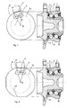
- Fig. 1 shows a side view of a rolling bearing according to the invention and a schematic plan view illustrating the length of the sensor strip as a function of the rolling element spacing.
- the reference numeral 2 refers to an outer ring of the bearing and the reference numeral 3 to an inner ring or on an inner ring half. Between the outer ring and the inner ring a plurality of rolling elements 5 is arranged in two rows.
- the reference numeral 7 refers to the rotating wheel flange.
- a sensor strip 4 is provided, which extends in the circumferential direction of the outer ring 2 and thus in a plane perpendicular to the plane of the figure.
- the reference numeral 11 denotes a sealing element and the reference numeral 12 a projection of the wheel flange 7 for the axial fixing of the inner ring halves third
- the outer periphery of the outer ring 2 is circular in this embodiment.
- the reference character Kw refers to the circular line of the rolling elements 5, d. H. the circle on which the centers or the axes of rotation of the rolling elements 5 are arranged.
- the reference symbol L denotes the active length of the sensor strip 4.
- the measuring grid length of the strain gauge corresponds to the rolling body distance d projected from the center point M on the lateral surface of the outer ring, or an integral multiple thereof.
- R is the radius of the peripheral surface of the outer ring
- n is the number of rolling elements 5 in a row.
- the active length depends here on the outer diameter of the outer ring 2.
- Fig. 2 shows another embodiment of the rolling bearing according to the invention.
- the essential difference lies in the configuration of the outer circumference of the outer ring 2.
- This has in the embodiment shown in FIG. 2 flattened areas 13, on which sensor strips are arranged.
- the length of the sensor strip running straight here could be determined, for example, for geometrical considerations with the aid of the radiation sets.
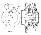
- Fig. 3 shows a further embodiment of the rolling bearing according to the invention.
- the sensor strip is arranged on a flattening 14 raised in relation to the circular shape of the outer ring.
- the strain gage is substantially rectilinear and its length may also result from geometrical considerations with the aid of the ray sets.
- the surface on which the strain gauge 4 is disposed may take other forms, but in any case it is crucial that the length of this strain gauge corresponds to the above-mentioned projection or a multiple thereof or adapted to it.
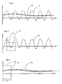
- Fig. 4 shows a comparison of the sensor signals.
- the reference numeral 17 refers to a recorded with a strain gauge according to the prior art signal.
- the signal has the above-mentioned periodic fluctuations caused by the passage of the rolling element arise at the strain gauge.
- the reference numeral 18 refers to a signal with a strain gauge according to the invention, which is adjusted by the periodic portion of the signal 17. In the case of the signal 17, this signal must be integrated over at least one signal period to determine the metrologically relevant DC component.
- the amplitude A is plotted against the time t.
- Fig. 5 shows such integration. More specifically, in Fig. 5, a time window 19 is shown indicating the minimum necessary window width for the moving averaging. The integration via this window gives the metrologically relevant value of the DC component.
- Fig. 6 shows an illustration of the time delay ⁇ t by the moving averaging.
- reference numeral 19 again refers to the time window necessary to perform averaging.
- the signal 17a recorded with a prior art strain gage and moving averaging is delayed by the time difference ⁇ t. H. relative to the corresponding signal, which was recorded with the strain gauge according to the invention, is offset. This can be omitted by the sensor strip according to the invention, the time delay.
Abstract
Description
Die vorliegende Erfindung bezieht sich auf ein Wälzlager mit einem Sensor. Die Erfindung wird unter Bezugnahme auf ein Wälzlager in einem Kraftfahrzeug beschrieben, es wird jedoch darauf hingewiesen, dass die Erfindung auch bei anderen Vorrichtungen, in denen Wälzlager eingesetzt werden, anwendbar ist.The present invention relates to a rolling bearing with a sensor. The invention will be described with reference to a rolling bearing in a motor vehicle, but it should be noted that the invention is also applicable to other devices in which rolling bearings are used.
Um die Sicherheit und den Fahrkomfort moderner Fahrzeuge weiter zu verbessern, benötigen die elektronischen Regelsysteme für den Fahrbetrieb im Fahrzeug zunehmend mehr Information über die aktuelle Fahrsituation. Zusätzlich zu den aktuellen Daten des Motors, des Getriebes und der Drehzahl der einzelnen Räder sollen auch die aktuellen Kräfte und Kraftrichtungen wie Radaufstandskräfte, die auf die einzelnen Reifen wirken, zur Regelung des Fahrbetriebs mit herangezogen werden. Um diese Kräfte zu erfassen sind aus dem Stand der Technik verschiedene Lösungsversuche bekannt. So ist es bekannt, bei einer Radlagereinheit an verschiedenen Stellen an dem jeweils stehenden Lagerring Sensoren anzuordnen. Aus den gemessenen Kräften an dem stehenden Ring des Radlagers können bei einer Geradeausfahrt oder bei einer Kurvenfahrt die Kräfte, die am Reifen wirken, bestimmt werden.In order to further improve the safety and ride comfort of modern vehicles, the electronic control systems for driving in the vehicle increasingly require more information about the current driving situation. In addition to the current data of the engine, the transmission and the speed of the individual wheels, the current forces and force directions, such as wheel contact forces acting on the individual tires, should also be used to control the driving operation. In order to detect these forces, various attempts at solution are known from the prior art. Thus, it is known to arrange at a wheel bearing unit at different locations on the respective stationary bearing ring sensors. From the measured Forces on the stationary ring of the wheel bearing, the forces acting on the tire can be determined during a straight-ahead or cornering.
Aus der
Die aus dem Stand der Technik bekannten Sensoren wie beispielsweise Dehnmessstreifen (DMS) geben bei der Messung der Kräfte ein periodisches Signal aus. Dieses Signal setzt sich zusammen aus einem periodischen Signal, welches punktsymmetrisch ist und einem Gleichanteil, der von der Belastung des Lagers abhängig ist. Der periodische Signalanteil entsteht durch die Relativbewegung der Wälzkörper gegenüber dem Sensorstreifen, d. h. die Periode hängt damit von der Wälzkörperumlauffrequenz und der Anzahl der Wälzkörper ab. Damit wird im Stand der Technik ein in Abhängigkeit von der Wälzkörperumlauffrequenz periodisches Signal gemessen. So treten beispielsweise bei einem Wälzlager mit zwölf Wälzkörpern pro Umlauf der Wälzkörper zwölf Perioden auf.The known from the prior art sensors such as strain gauges (DMS) give in the measurement of forces a periodic signal. This signal is composed of a periodic signal, which is point-symmetrical and a DC component, which depends on the load of the bearing. The periodic signal component is caused by the relative movement of the rolling elements relative to the sensor strip, d. H. the period thus depends on the Wälzkörperumlauffrequenz and the number of rolling elements. Thus, a periodic signal is measured in the prior art as a function of the Wälzkörperumlauffrequenz. Thus, for example, occur in a rolling bearing with twelve rolling elements per revolution of the rolling elements on twelve periods.
Messtechnisch interessant ist der Gleichanteil aus dem die jeweils wirkenden Kräfte ermittelt werden. Im Stand der Technik werden gleitende Mittelwertfilter mit der Fensterbreite einer Signalperiode verwendet. Auch ist es bekannt, das Signal über die Signalperiode integrieren, um den Gleichanteil von dem periodischen Signal zu trennen.Metrologically interesting is the DC component from which the respective acting forces are determined. The prior art uses moving average filters with the window width of a signal period. It is also known to integrate the signal over the signal period to separate the DC component from the periodic signal.
Bei dieser Methode tritt jedoch das Problem auf, dass zwischen dem Auftreten eines Kraft- oder Momentenereignisses bis zur Ausgabe des dadurch entstandenen Gleichanteils der gemessenen Dehnung ein Zeitversatz auftritt, der proportional zur Dauer einer Signalperiode ist. Daneben ist es nicht möglich, bei einem stehendem Lager ohne Kenntnis der Wälzkörperposition von den gemessenen Dehnungen auf die wirkende Kräfte und Momente zurück zu schließen, da, wie erwähnt, das von dem DMS-Streifen ausgegebene Signal auch von der Lage der Wälzkörper gegenüber dem DMS-Streifen abhängt.In this method, however, the problem arises that between the occurrence of a force or torque event until the issue of the resulting DC component of the measured strain a time offset occurs, which is proportional to the duration of a signal period. In addition, it is not possible for a stationary bearing without knowledge of the rolling element from the measured strains on the forces acting and moments back, since, as mentioned, the signal output from the DMS strip also depends on the position of the rolling elements relative to the DMS strip.
Der vorliegenden Erfindung liegt daher die Aufgabe zugrunde, ein kraft- und Momente messendes Wälzlagers zur Verfügung zu stellen, welches sowohl im Stillstand als auch in allen Drehzahlenbereichen, in denen das Lager betrieben werden kann, eine drehzahlunabhängige und qualitativ gleich bleibende Signalerfassung bzw. Auswertung und Ausgabe ermöglicht. Daneben soll das Auswerteverfahren vereinfacht werden und insbesondere auf die Verwendung zusätzlicher Filter wie ein gleitender Mittelwertfilter und dergleichen verzichtet werden. Weiterhin soll die Signalerfassung vereinfacht werden.The present invention is therefore an object of the invention to provide a force and moments measuring rolling bearing available, which both at standstill and in all speed ranges in which the bearing can be operated, a speed-independent and qualitatively constant signal detection and evaluation and Edition possible. In addition, the evaluation procedure should be simplified and in particular the use of additional filters such as a sliding average filter and the like should be dispensed with. Furthermore, the signal acquisition should be simplified.
Dies wird erfindungsgemäß durch ein Wälzlager nach Anspruch 1 erreicht. Vorteilhafte Ausführungsformen und Weiterbildungen sind Gegenstand der Unteransprüche.This is inventively achieved by a rolling bearing according to claim 1. Advantageous embodiments and further developments are the subject of the dependent claims.
Das erfindungsgemäße Wälzlager weist einen Außenring und einen Innenring auf und eine Vielzahl von zwischen dem Außenring und dem Innenring angeordneten Wälzkörpern. Dabei weist das Wälzlager wenigstens einen Sensorstreifen auf, der an einer Umfangsfläche wenigstens eines Lagerrings angeordnet ist. Erfindungsgemäß weist der Sensorstreifen eine vorgegebene aktive Länge auf und diese aktive Länge ist unter Berücksichtigung des Abstandes zweier benachbarter Wälzkörper festgelegt. Dabei kann der Sensorstreifen an der Umfangsfläche angeordnet sein, er kann jedoch auch an einem an die Umfangsfläche angrenzenden Gehäuseteil vorgesehen sein.The rolling bearing according to the invention has an outer ring and an inner ring and a plurality of arranged between the outer ring and the inner ring rolling elements. In this case, the rolling bearing has at least one sensor strip, which is arranged on a peripheral surface of at least one bearing ring. According to the invention, the sensor strip has a predetermined active length and this active length is determined taking into account the distance between two adjacent rolling elements. In this case, the sensor strip may be arranged on the peripheral surface, but it may also be provided on a housing part adjacent to the peripheral surface.
Der Abstand zweier benachbarter Wälzkörper kann einerseits direkt der geometrische Abstand der Mittelpunkte dieser beiden Wälzkörper sein. Daneben ist es auch möglich, den Abstand über den Winkel, den die jeweiligen Mittelpunkte der beiden Wälzkörper bezüglich des Lagermittelpunkts miteinander einschließen, zu bestimmen.The distance between two adjacent rolling elements can be directly on the one hand, the geometric distance of the centers of these two rolling elements. In addition, it is also possible to adjust the distance over the angle that the respective Include centers of the two rolling elements with respect to the bearing center point to determine.
Unter der aktiven Länge des Sensorstreifens wird diejenige Länge verstanden, über die hinweg die auf den Sensorstreifen übertragenen Kräfte ermittelt werden. Insbesondere handelt es sich dabei um die Messgitterlänge eines DMS bzw. den Bereich der Dehnungsübertragung auf dem DMS.The active length of the sensor strip is understood to be the length over which the forces transmitted to the sensor strip are determined. In particular, this involves the measuring grid length of a strain gage or the area of strain transmission on the strain gage.
Bevorzugt handelt es sich bei der Umfangsfläche um eine den Wälzkörpern abgewandte Umfangsfläche.The peripheral surface is preferably a circumferential surface facing away from the rolling bodies.
Unter der den Wälzkörpern abgewandten Umfangsfläche, wird diejenige Umfangsfläche eines Innen- oder Außenrings verstanden, die nicht mit den Wälzkörpern in Kontakt steht. Im Falle des Außenrings handelt es sich insbesondere um den Außenumfang desselben und im Falle des Innenrings um dessen Innenumfang.Under the circumferential surface facing away from the rolling elements, that peripheral surface of an inner or outer ring is understood, which is not in contact with the rolling elements. In the case of the outer ring, it is in particular the outer circumference of the same and in the case of the inner ring around its inner circumference.
Durch die Berücksichtigung des Abstandes zweier benachbarter Wälzkörper bei der Festlegung der aktiven Länge des Sensormessstreifens, können diejenigen Messeffekte, welche durch das Vorbeiführen der Wälzkörper an dem Messstreifen entstehen, unterdrückt werden und damit bereits das gemessene Signal von dem oben beschriebenen periodischen Anteil befreit werden.By taking into account the distance between two adjacent rolling elements in determining the active length of the sensor measuring strip, those measuring effects, which are caused by the passing of the rolling elements on the measuring strip, can be suppressed and thus already freed the measured signal from the periodic component described above.
Vorzugsweise ist die aktive Länge ein ganzzahliges Vielfaches des auf die abgewandte Umfangsfläche projizierten Abstandes der benachbarten Wälzkörper. Bei dieser Ausführungsform wird durch diese spezielle geometrische Form eine Mittelung des gemessenen Signals erreicht. Insbesondere wird kein periodisches Signal ausgegeben, da das von dem Sensorstreifen ausgegebene Signal unabhängig von der genauen Position der Wälzkörper bezüglich des Sensorstreifens ist. Damit wird durch diese Ausführungsform die gleitende Mittelwertbildung aus dem Stand der Technik im Zeitbereich des Sensorstreifen-Signals durch eine geometrische Mittelung durch die gezielte Formgebung des Sensorstreifens ersetzt. Diese geometrische Mittelung erzeugt keinen Zeitversatz.Preferably, the active length is an integer multiple of the distance projected to the remote circumferential surface of the adjacent rolling elements. In this embodiment, an averaging of the measured signal is achieved by this special geometric shape. In particular, no periodic signal is output because the signal output from the sensor strip is independent of the exact position of the rolling elements with respect to the sensor strip. Thus, by this embodiment, the moving averaging of the prior art in the time domain of Sensor strip signal replaced by a geometric averaging by the targeted shaping of the sensor strip. This geometric averaging does not produce a time offset.
Genauer entspricht bei Verwendung eines DMS als Sensorstreifen sowohl die Messgitterlänge des DMS als auch der Bereich der Dehnungsübertragung auf den DMS dem auf die abgewandte Umfangsfläche projizierten Wälzkörperabstand oder einem ganzzahligen Vielfachen davon.More specifically, when using a strain gage as the sensor strip, both the gage length of the gage and the strain gearing area on the strain gage correspond to the rolling element pitch projected on the opposite circumferential surface or an integer multiple thereof.
Falls beispielsweise der Sensorstreifen auf dem Außenring angeordnet ist, wäre insoweit die Mantelfläche dieses Außenrings für die Bestimmung der Messgitterlänge und der Dehnungsübertragung des DMS entscheidend.If, for example, the sensor strip is arranged on the outer ring, the lateral surface of this outer ring would be decisive for the determination of the measuring grid length and the strain transmission of the DMS.
Bei anderen Ausführungsformen kann jedoch die aktive Länge auch beispielsweise geringfügig geringer oder höher als der auf die abgewandte Umfangsfläche projizierte Abstand sein. In diesem Falle würde neben dem Gleichanteil auch ein geringfügiger periodischer Anteil ausgegebenen werden, der gleichzeitig als Maß für die Umlauffrequenz der Wälzkörper verwendet werden könnte. Entscheidend ist jedoch, dass sich, wie oben gesagt, die aktive Länge des Sensorstreifens an dem Wälzkörperabstand orientiert.However, in other embodiments, the active length may also be, for example, slightly less or higher than the distance projected on the opposite circumferential surface. In this case, in addition to the DC component, a small periodic component would also be output, which could at the same time be used as a measure of the rotational frequency of the rolling bodies. The decisive factor, however, is that, as stated above, the active length of the sensor strip is oriented at the rolling element spacing.
Unter dem projizierten Abstand wird eine Projektion ausgehend vom Mittelpunkt des Wälzlagers verstanden. Je nach der Formgebung der entsprechenden Umfangsfläche kann es sich bei der projizierten Fläche um eine ebene oder gekrümmte Fläche handeln.The projected distance is understood to mean a projection starting from the center of the rolling bearing. Depending on the shape of the corresponding peripheral surface, the projected surface may be a flat or curved surface.
Vorzugsweise ist die aktive Länge der auf die abgewandte Umfangsfläche projizierte Abstand zweier benachbarter Wälzkörper. Dies stellt den Spezialfall dar, dass es sich bei dem ganzzahligen Vielfachen das genau Einfache des projizierten Abstandes der benachbarten Wälzkörper handelt.Preferably, the active length of the projected on the opposite peripheral surface distance between two adjacent rolling elements. This represents the special case that the integer multiple is the exact simple of the projected distance of the adjacent rolling elements.
Bei einer bevorzugten Ausführungsform ist der Sensorstreifen auf einem ruhenden Lagerring angeordnet. Diese Vorgehensweise ist vorteilhaft, da einerseits die gemessenen Signale einfacher übertragen werden können und andererseits bei der Auswertung der Kräfte nicht die jeweilige Drehposition eines drehenden Rings berücksichtigt werden muss.In a preferred embodiment, the sensor strip is arranged on a stationary bearing ring. This procedure is advantageous because, on the one hand, the measured signals can be transmitted more easily and, on the other hand, when evaluating the forces, the respective rotational position of a rotating ring need not be taken into account.
Bei einer weiteren bevorzugten Ausführungsform ist der Sensorstreifen auf dem Außenring des Lagers angeordnet. Dies bedeutet, dass, wie oben erwähnt, die Messgitterlänge des Sensorstreifens in diesem Fall dem auf die Mantelfläche des Außenrings projizierten Wälzkörperabstand oder einen ganzzahligen Vielfachen davon entspricht.In a further preferred embodiment, the sensor strip is arranged on the outer ring of the bearing. This means that, as mentioned above, the measuring grid length of the sensor strip in this case corresponds to the rolling body distance projected onto the outer surface of the outer ring or an integral multiple thereof.
Bei einer weiteren bevorzugten Ausführungsform ist eine Vielzahl von Sensorstreifen vorgesehen. Diese Sensorstreifen sind an dem jeweils ruhenden Lagerring an festen vorbestimmten Positionen angeordnet. Diese Positionen sind im Hinblick auf die zu messenden Kräfte ausgewählt, beispielsweise im Hinblick auf zu messende Gewichtskräfte, zu messende Bremskräfte oder auch zu bestimmende Reibbeiwerte.In a further preferred embodiment, a plurality of sensor strips is provided. These sensor strips are arranged on the respective stationary bearing ring at fixed predetermined positions. These positions are selected with regard to the forces to be measured, for example with regard to weight forces to be measured, braking forces to be measured or friction coefficients to be determined.
Vorzugsweise handelt es sich bei den Sensorstreifen um einen DMS-Streifen. Mit diesen Dehnungsmessstreifen oder Dünnschicht-Dehnungsmessstreifen können die Reaktionskräfte (die Spannungsveränderung) an dem jeweils feststehenden Lagerring des Radlagers ermittelt werden. Bei einer Fahrt ohne bremsen können aus diesen Belastungen direkt die Radaufstandskräfte ermittelt werden. In einer bevorzugten Ausführungsform könne auch Halbleiter-DMS verwendet werden. Diese bieten den Vorteil geringer Abmessungen.Preferably, the sensor strips are a DMS strip. These strain gauges or thin-film strain gauges can be used to determine the reaction forces (the change in tension) on the respectively fixed bearing ring of the wheel bearing. When driving without braking, the wheel contact forces can be determined directly from these loads. In a preferred embodiment, semiconductor DMS may also be used. These offer the advantage of small dimensions.
Anstelle eines Dehnmessstreifens wäre es auch möglich, neuerdings bekannt gewordene PZT (Blei-Zirkonat-Titanat) Fasern einzusetzen. Derartige Sensoren basieren auf dem piezoelektrischen Effekt. Die Fasern können dabei beispielsweise mit Epoxidharz vergossen werden.Instead of a strain gauge, it would also be possible to use recently known PZT (lead zirconate titanate) fibers. Such sensors are based on the piezoelectric effect. The fibers can be cast, for example, with epoxy resin.
Die vorliegende Erfindung ist weiterhin auf ein Fahrzeug und insbesondere auf ein Kraftfahrzeug mit einem Wälzlager der oben beschriebenen Art gerichtet.The present invention is further directed to a vehicle, and more particularly to a motor vehicle having a rolling bearing of the type described above.
Weitere Vorteile und Ausführungsformen ergeben sich aus den beigefügten Zeichnungen.Further advantages and embodiments will become apparent from the accompanying drawings.
Darin zeigen:
- Fig. 1
- eine Darstellung zur Geometrie eines Sensorstreifens in einer ersten Ausführungsform;
- Fig. 2
- eine Darstellung zur Geometrie eines Sensorstreifens in einer zweiten Ausführungsform;
- Fig. 3
- eine Darstellung zur Geometrie eines Sensorstreifens in einer dritten Ausführungsform;
- Fig. 4
- eine Darstellung eines mit einem erfindungsgemäßen DMS aufgenommenen Signals;
- Fig. 5
- eine Signalverarbeitung nach dem Stand der Technik; und
- Fig. 6
- eine Darstellung des zeitlichen Verzuges im Vergleich.
- Fig. 1
- a representation of the geometry of a sensor strip in a first embodiment;
- Fig. 2
- a representation of the geometry of a sensor strip in a second embodiment;
- Fig. 3
- a representation of the geometry of a sensor strip in a third embodiment;
- Fig. 4
- a representation of a signal recorded with a DMS according to the invention signal;
- Fig. 5
- a signal processing according to the prior art; and
- Fig. 6
- a representation of the time delay in comparison.
Fig. 1 zeigt eine Seitenansicht eines erfindungsgemäßen Wälzlagers sowie eine schematische Draufsicht zur Veranschaulichung der Länge des Sensorstreifens in Abhängigkeit von dem Wälzkörper-Abstand.Fig. 1 shows a side view of a rolling bearing according to the invention and a schematic plan view illustrating the length of the sensor strip as a function of the rolling element spacing.
Dabei bezieht sich das Bezugszeichen 2 auf einen Außenring des Lagers und das Bezugszeichen 3 auf einen Innenring bzw. auf eine Innenringhälfte. Zwischen dem Außenring und dem Innenring ist eine Vielzahl von Wälzkörpern 5 in zwei Reihen angeordnet.In this case, the
Das Bezugszeichen 7 bezieht sich auf den sich drehenden Radflansch. An dem Außenumfang des Außenrings 2 ist bei der in Fig. 1 gezeigten Ausführungsform ein Sensorstreifen 4 vorgesehen, der sich in der Umfangsrichtung des Außenrings 2 und damit in einer Ebene senkrecht zur Figurenebene erstreckt. Das Bezugszeichen 11 kennzeichnet ein Abdichtelement und das Bezugszeichen 12 einen Vorsprung des Radflansches 7 zur axialen Fixierung der Innenringhälften 3.The
Wie sich aus dem linken schematischen Teilbild von Fig. 1 ergibt, ist der Außenumfang des Außenrings 2 bei dieser Ausführungsform kreisförmig ausgebildet. Dabei bezieht sich das Bezugszeichen Kw auf die Kreislinie der Wälzkörper 5, d. h. diejenige Kreislinie, auf der die Mittelpunkte bzw. die Drehachsen der Wälzkörper 5 angeordnet sind. Das Bezugszeichen L kennzeichnet die aktive Länge des Sensorstreifens 4.As is apparent from the left schematic part of Fig. 1, the outer periphery of the
Wie eingangs erwähnt, entspricht die Messgitterlänge des Dehnmessstreifen dem auf die Mantelfläche des Außenrings ausgehend vom Mittelpunkt M projizierten Wälzkörperabstand d oder einem ganzzahligen Vielfachen davon.As mentioned at the beginning, the measuring grid length of the strain gauge corresponds to the rolling body distance d projected from the center point M on the lateral surface of the outer ring, or an integral multiple thereof.
Bei der in Fig. 1 gezeigten Ausführungsform könnte die aktive Länge ein L des Messstreifens auch ausgedrückt werden durch den Zusammenhang ![]()
wobei R der Radius der Umfangsfläche des Außenrings und n die Anzahl der Wälzkörper 5 in einer Reihe ist. Damit hängt die aktive Länge hier von dem Außendurchmesser des Außenrings 2 ab.In the embodiment shown in Fig. 1, the active length L of the measuring strip could also be expressed by the context ![]()
where R is the radius of the peripheral surface of the outer ring and n is the number of
Fig. 2 zeigt eine weitere Ausführungsform des erfindungsgemäßen Wälzlagers. Der wesentliche Unterschied liegt hier in der Ausgestaltung des Außenumfangs des Außenrings 2. Dieser weist bei der in Fig. 2 gezeigten Ausführungsform abgeflachte Bereiche 13 auf, auf denen Sensorstreifen angeordnet sind. Auch bei dieser Ausführungsform könnte die Länge des hier gerade verlaufenden Sensorstreifens beispielsweise aus geometrischen Überlegungen unter zu Hilfenahme der Strahlensätze ermittelt werden.Fig. 2 shows another embodiment of the rolling bearing according to the invention. The essential difference lies in the configuration of the outer circumference of the
Fig. 3 zeigt eine weitere Ausführungsform des erfindungsgemäßen Wälzlagers. Hier ist der Sensorstreifen an einer gegenüber der Kreisform des Außenrings erhabenen Abflachung 14 angeordnet. Auch in diesem Fall verläuft der DMS im Wesentlichen geradlinig und seine Länge kann sich ebenfalls aus geometrischen Überlegungen unter zu Hilfenahme der Strahlensätze ergeben.Fig. 3 shows a further embodiment of the rolling bearing according to the invention. Here, the sensor strip is arranged on a flattening 14 raised in relation to the circular shape of the outer ring. Also in this case, the strain gage is substantially rectilinear and its length may also result from geometrical considerations with the aid of the ray sets.
Zusätzlich zu den in den Figuren 1 - 3 gezeigten Ausführungsformen kann jedoch die Oberfläche, auf dem der Dehnmessstreifen 4 angeordnet ist, auch andere Formen annehmen, entscheidend ist jedoch in jedem Fall, dass die Länge dieses Dehnmessstreifens der oben erwähnten Projektion oder einem Vielfachen davon entspricht oder daran angepasst ist.In addition to the embodiments shown in FIGS. 1-3, however, the surface on which the strain gauge 4 is disposed may take other forms, but in any case it is crucial that the length of this strain gauge corresponds to the above-mentioned projection or a multiple thereof or adapted to it.
Fig. 4 zeigt einen Vergleich der Sensorssignale. Dabei bezieht sich das Bezugszeichen 17 auf ein mit einem Dehnmessstreifen nach dem Stand der Technik aufgenommenes Signal. Hier weist das Signal die oben erwähnten periodischen Schwankungen auf, die durch die Vorbeibewegung des Wälzkörpers an dem Dehnmessstreifen entstehen. Das Bezugszeichen 18 bezieht sich auf ein Signal mit einem erfindungsgemäßen Dehnmessstreifen, welches von dem periodischen Anteil des Signals 17 bereinigt ist. Im Fall des Signals 17 muss zur Ermittelung des messtechnisch relevanten Gleichanteils dieses Signal über wenigstens eine Signalperiode integriert werden. In den Figuren 4 - 6 ist die Amplitude A gegenüber der Zeit t aufgetragen.Fig. 4 shows a comparison of the sensor signals. In this case, the
Fig. 5 zeigt eine derartige Integration. Genauer gesagt ist in Fig. 5 ein Zeitfenster 19 gezeigt, welches die mindestens nötige Fensterbreite für die gleitende Mittelwertbildung anzeigt. Die Integration über dieses Fenster ergibt den messtechnisch relevanten Wert des Gleichanteils.Fig. 5 shows such integration. More specifically, in Fig. 5, a
Fig. 6 zeigt eine Veranschaulichung des Zeitverzugs Δt durch die gleitende Mittelwertbildung. Hier bezieht sich das Bezugszeichen 19 wiederum auf das Zeitfenster, welches nötig ist, um eine Mittelwertbildung durchzuführen. Bei zeitlicher Betrachtung ergibt sich, dass das Signal 17a, das mit einem Dehnmessstreifen nach dem Stand der Technik und gleitender Mittelwertbildung aufgenommen wurde, um die zeitliche Differenz Δt verspätet ist, d. h. gegenüber dem entsprechenden Signal, welches mit dem erfindungsgemäßen Dehnmessstreifen aufgenommen wurde, versetzt ist. Damit kann durch den erfindungsgemäßen Sensorstreifen der zeitliche Verzug entfallen.Fig. 6 shows an illustration of the time delay Δt by the moving averaging. Here,
Sämtliche in den Anmeldungsunterlagen offenbarten Merkmale werden als erfindungswesentlich beansprucht, sofern sie einzeln oder in Kombination gegenüber dem Stand der Technik neu sind.All disclosed in the application documents features are claimed as essential to the invention, provided they are new individually or in combination over the prior art.
- 11
- Wälzlagerroller bearing
- 22
- Außenringouter ring
- 33
- Innenring bzw. InnenringhälfteInner ring or inner ring half
- 44
- Sensorstreifensensor strip
- 55
- Wälzkörperrolling elements
- 66
-
Umfangsfläche des Außenrings 2Peripheral surface of the
outer ring 2 - 77
- sich drehender Radflanschrotating wheel flange
- 1111
- Abdichtelementsealing
- 1212
-
Vorsprung des Radflansches 7Projection of the
wheel flange 7 - 1313
- abgeflachte Bereicheflattened areas
- 1414
- erhabene Abflachungraised flattening
- 1717
- Signal mit Sensorstreifen nach Stand der TechnikSignal with sensor strips according to the prior art
- 17a17a
- zeitversetztes Signaltime-shifted signal
- 1818
- Signal mit erfindungsgemäßen SensorstreifenSignal with sensor strips according to the invention
- 1919
- ZeitfensterTime window
- dd
- Wälzkörperabstandrolling element
- LL
- aktive Länge des Sensorstreifensactive length of the sensor strip
- MM
- MittelpunktFocus
- nn
- Anzahl der WälzkörperNumber of rolling elements
- RR
- Radiusradius
- Kwkw
- Kreislinie der WälzkörperCircular line of the rolling elements
- Δt.delta.t
- Zeitverzugdelay
- AA
- Amplitudeamplitude
- tt
- ZeitTime
Claims (9)
dadurch gekennzeichnet, dass
der Sensorstreifen eine vorgegebene aktive Länge (L) aufweist und diese aktive Länge (L) unter Berücksichtigung des Abstandes (d) zweier benachbarter Wälzkörper (5) festgelegt ist.Rolling bearing having an outer ring (2), an inner ring (3) and a plurality of between the outer ring (2) and the inner ring (3) arranged rolling elements (5), wherein the rolling bearing (1) has at least one sensor strip (4) is arranged on a circumferential surface (6) of at least one bearing ring (2, 3),
characterized in that
the sensor strip has a predetermined active length (L) and this active length (L) is determined taking into account the distance (d) of two adjacent rolling elements (5).
dadurch gekennzeichnet, dass
die Umfangsfläche (6) eine den Wälzkörpern (5) abgewandte Umfangsfläche (6) ist.Rolling bearing according to claim 1,
characterized in that
the circumferential surface (6) is a circumferential surface (6) facing away from the rolling elements (5).
dadurch gekennzeichnet, dass
die aktive Länge ein ganzzahliges Vielfaches des auf die abgewandte Umfangsfläche (6) projiziertem Abstandes (d) der benachbarten Wälzkörper ist (5).Rolling bearing according to claim 1,
characterized in that
the active length is an integer multiple of the distance (d) of the adjacent rolling bodies projected onto the remote circumferential surface (6) (5).
dadurch gekennzeichnet, dass
die aktive Länge der auf die abgewandte Umfangsfläche (6) projizierte Abstand (d) zweier benachbarten Wälzkörper (5) ist.Rolling bearing according to at least one of the preceding claims,
characterized in that
the active length of the distance (d) of two adjacent rolling elements (5) projected onto the remote circumferential surface (6).
dadurch gekennzeichnet, dass
der Sensorstreifen (4) auf einem ruhenden Lagerring (2,3) angeordnet ist.Rolling bearing according to at least one of the preceding claims,
characterized in that
the sensor strip (4) is arranged on a stationary bearing ring (2, 3).
dadurch gekennzeichnet, dass
der Sensorstreifen auf dem Außenring (2) des Lagers angeordnet ist.Rolling bearing according to at least one of the preceding claims,
characterized in that
the sensor strip is arranged on the outer ring (2) of the bearing.
dadurch gekennzeichnet, dass
eine Vielzahl von Sensorstreifen (4) vorgesehen ist.Rolling bearing according to at least one of the preceding claims,
characterized in that
a plurality of sensor strips (4) is provided.
dadurch gekennzeichnet, dass
der Sensorstreifen (4) ein DMS-Streifen (4) oder ein Sensor auf Basis eines piezoelektrischen Effekts, insbesondere eine PZT (Blei-Zirkonat-Titanat) Faser, ist.Rolling bearing according to at least one of the preceding claims,
characterized in that
the sensor strip (4) is a strain gauge strip (4) or a sensor based on a piezoelectric effect, in particular a PZT (lead zirconate titanate) fiber.
Applications Claiming Priority (1)
| Application Number | Priority Date | Filing Date | Title |
|---|---|---|---|
| DE200610016476 DE102006016476A1 (en) | 2006-04-07 | 2006-04-07 | Rolling bearing with sensor |
Publications (2)
| Publication Number | Publication Date |
|---|---|
| EP1843055A1 true EP1843055A1 (en) | 2007-10-10 |
| EP1843055B1 EP1843055B1 (en) | 2012-10-31 |
Family
ID=38169693
Family Applications (1)
| Application Number | Title | Priority Date | Filing Date |
|---|---|---|---|
| EP20070006804 Not-in-force EP1843055B1 (en) | 2006-04-07 | 2007-03-31 | Roller bearing with sensor |
Country Status (2)
| Country | Link |
|---|---|
| EP (1) | EP1843055B1 (en) |
| DE (1) | DE102006016476A1 (en) |
Cited By (4)
| Publication number | Priority date | Publication date | Assignee | Title |
|---|---|---|---|---|
| WO2009076988A1 (en) * | 2007-12-18 | 2009-06-25 | Ab Skf | Bearing and sensor unit |
| EP2090793A1 (en) * | 2008-02-14 | 2009-08-19 | SNR Roulements | Roller bearing with differential rigidity of zones instrumented by deformation |
| EP2107260A1 (en) * | 2008-04-03 | 2009-10-07 | SNR Roulements | Rolling bearing with at least one axially limited and deformation sensitive area delivering a deformation signal |
| EP2311652A1 (en) * | 2008-08-05 | 2011-04-20 | JTEKT Corporation | Rolling bearing device |
Families Citing this family (4)
| Publication number | Priority date | Publication date | Assignee | Title |
|---|---|---|---|---|
| WO2009092390A1 (en) * | 2008-01-22 | 2009-07-30 | Ab Skf | Bearing and sensor unit |
| DE102010047928A1 (en) | 2010-10-08 | 2012-04-12 | Schaeffler Technologies Gmbh & Co. Kg | Rolling bearing for rotary bearing of a machine element |
| DE102011085258A1 (en) * | 2011-10-26 | 2013-05-02 | Aktiebolaget Skf | Bearing ring, bearing ring segment, bearing and method for setting a preload of a rolling bearing |
| DE102017214815A1 (en) * | 2017-08-24 | 2019-02-28 | Robert Bosch Gmbh | Carriage with a piezoresistive layer for load measurement |
Citations (4)
| Publication number | Priority date | Publication date | Assignee | Title |
|---|---|---|---|---|
| EP0018936A1 (en) * | 1979-03-22 | 1980-11-12 | Lechler, Gerhard, Dr.Ing. | Force measuring device for roller bearings |
| JPH06341430A (en) | 1993-06-02 | 1994-12-13 | Agency Of Ind Science & Technol | Rolling bearing with sensor |
| US5952587A (en) * | 1998-08-06 | 1999-09-14 | The Torrington Company | Imbedded bearing life and load monitor |
| DE10136438A1 (en) * | 2000-08-22 | 2002-03-07 | Bosch Gmbh Robert | Sensor arrangement for direct measurement of forces and moments acting on bearing box and derivation from these of other values useful in automatic vehicle control systems |
Family Cites Families (4)
| Publication number | Priority date | Publication date | Assignee | Title |
|---|---|---|---|---|
| DE2746937C2 (en) * | 1977-10-17 | 1986-11-06 | Gerhard Dr.-Ing. 1000 Berlin Lechler | Force measuring device |
| DE19522543A1 (en) * | 1994-08-01 | 1996-02-08 | Ntn Toyo Bearing Co Ltd | Piezoelectric measuring sensor system for roller bearings |
| DE10105298C1 (en) * | 2001-02-02 | 2002-08-14 | Fag Automobiltechnik Ag | Wheel bearing unit for measuring the contact forces between tires and road |
| DE10250340B4 (en) * | 2002-10-29 | 2016-06-09 | Schaeffler Technologies AG & Co. KG | As a rolling bearing trained Kraftmeßlager |
-
2006
- 2006-04-07 DE DE200610016476 patent/DE102006016476A1/en not_active Ceased
-
2007
- 2007-03-31 EP EP20070006804 patent/EP1843055B1/en not_active Not-in-force
Patent Citations (4)
| Publication number | Priority date | Publication date | Assignee | Title |
|---|---|---|---|---|
| EP0018936A1 (en) * | 1979-03-22 | 1980-11-12 | Lechler, Gerhard, Dr.Ing. | Force measuring device for roller bearings |
| JPH06341430A (en) | 1993-06-02 | 1994-12-13 | Agency Of Ind Science & Technol | Rolling bearing with sensor |
| US5952587A (en) * | 1998-08-06 | 1999-09-14 | The Torrington Company | Imbedded bearing life and load monitor |
| DE10136438A1 (en) * | 2000-08-22 | 2002-03-07 | Bosch Gmbh Robert | Sensor arrangement for direct measurement of forces and moments acting on bearing box and derivation from these of other values useful in automatic vehicle control systems |
Cited By (9)
| Publication number | Priority date | Publication date | Assignee | Title |
|---|---|---|---|---|
| WO2009076988A1 (en) * | 2007-12-18 | 2009-06-25 | Ab Skf | Bearing and sensor unit |
| EP2090793A1 (en) * | 2008-02-14 | 2009-08-19 | SNR Roulements | Roller bearing with differential rigidity of zones instrumented by deformation |
| FR2927678A1 (en) * | 2008-02-14 | 2009-08-21 | Snr Roulements Sa | BEARING BEARING WITH DIFFERENTIAL RIGIDITY OF DEFORMED INSTRUMENT ZONES |
| US8308369B2 (en) | 2008-02-14 | 2012-11-13 | Snr Roulements | Roller bearing with differential rigidity in the instrumented areas in deformation |
| EP2107260A1 (en) * | 2008-04-03 | 2009-10-07 | SNR Roulements | Rolling bearing with at least one axially limited and deformation sensitive area delivering a deformation signal |
| FR2929670A1 (en) * | 2008-04-03 | 2009-10-09 | Snr Roulements Soc Par Actions | BEARING BEARING COMPRISING AT LEAST ONE DEFORMED INSTRUMENT AREA THAT IS DELIMITED AXIALLY. |
| EP2311652A1 (en) * | 2008-08-05 | 2011-04-20 | JTEKT Corporation | Rolling bearing device |
| EP2311652A4 (en) * | 2008-08-05 | 2012-04-11 | Jtekt Corp | Rolling bearing device |
| US8690448B2 (en) | 2008-08-05 | 2014-04-08 | Jtekt Corporation | Rolling bearing device |
Also Published As
| Publication number | Publication date |
|---|---|
| DE102006016476A1 (en) | 2007-11-08 |
| EP1843055B1 (en) | 2012-10-31 |
Similar Documents
| Publication | Publication Date | Title |
|---|---|---|
| EP1843055B1 (en) | Roller bearing with sensor | |
| EP2877352B1 (en) | Method and device for estimating a profile depth of a tyre | |
| EP2276658B1 (en) | Measurement bearing, in particular for a wheel set of a rail vehicle | |
| DE60031305T2 (en) | bearing device | |
| DE19908701A1 (en) | Method and device for determining the emergency running condition of a pneumatic tire | |
| EP1353150B1 (en) | Angle detector | |
| DE102006057539A1 (en) | Method for mounting a detector mechanism of a planetary gear device | |
| EP2607856A2 (en) | Device for measuring torque, direction and rotation speed of a shaft of a gear unit, in particular of a drive shaft of an azimuth gear drive of a wind turbine | |
| DE102014204025A1 (en) | Component with a at least one sensor having measuring element | |
| DE102017126906A1 (en) | Achsrotations torque sensor | |
| WO2016165888A1 (en) | Actuator for a rear-wheel steering system of a motor vehicle | |
| EP2735766A1 (en) | Tilt drive or worm gear system and machine, assembly or vehicle component equipped with the same | |
| DE102018129119A1 (en) | Suspension actuator for a rear axle steering | |
| EP3328702A1 (en) | Method and system for analysing the wear behaviour of brake linings | |
| EP3268635A1 (en) | Planetary transmission | |
| DE102006031456B4 (en) | Storage arrangement with integrated torque measurement and device for controlling a torque distribution | |
| EP2786110B1 (en) | Method for monitoring the state of a bearing guiding an electric motor on a shaft | |
| DE10019710A1 (en) | Speed sensor for a differential axle of a vehicle includes a tone wheel formed by a rolling form tool attached to a hollow wheel flange in the body section of the differential housing | |
| DE102008046270B4 (en) | Direction indicator and method for determining the direction of rotation of a wheel | |
| DE102015221745A1 (en) | Method and device for determining a torque and drive unit | |
| DE10303876A1 (en) | Measuring arrangement, rolling bearing and method for determining the direction of movement of a rolling bearing component | |
| EP2980551B1 (en) | Motor vehicle brake test bench | |
| EP0935129A2 (en) | Multi-component measuring wheel | |
| EP1795881B1 (en) | Method and device for estimating the operating condition of a vehicle tyre | |
| WO2008138369A1 (en) | Method and device for determining a torque loading of a driveshaft |
Legal Events
| Date | Code | Title | Description |
|---|---|---|---|
| PUAI | Public reference made under article 153(3) epc to a published international application that has entered the european phase |
Free format text: ORIGINAL CODE: 0009012 |
|
| AK | Designated contracting states |
Kind code of ref document: A1 Designated state(s): AT BE BG CH CY CZ DE DK EE ES FI FR GB GR HU IE IS IT LI LT LU LV MC MT NL PL PT RO SE SI SK TR |
|
| AX | Request for extension of the european patent |
Extension state: AL BA HR MK YU |
|
| 17P | Request for examination filed |
Effective date: 20071123 |
|
| 17Q | First examination report despatched |
Effective date: 20071221 |
|
| AKX | Designation fees paid |
Designated state(s): AT BE BG CH CY CZ DE DK EE ES FI FR GB GR HU IE IS IT LI LT LU LV MC MT NL PL PT RO SE SI SK TR |
|
| RAP1 | Party data changed (applicant data changed or rights of an application transferred) |
Owner name: SCHAEFFLER TECHNOLOGIES AG & CO. KG |
|
| GRAP | Despatch of communication of intention to grant a patent |
Free format text: ORIGINAL CODE: EPIDOSNIGR1 |
|
| GRAS | Grant fee paid |
Free format text: ORIGINAL CODE: EPIDOSNIGR3 |
|
| GRAA | (expected) grant |
Free format text: ORIGINAL CODE: 0009210 |
|
| AK | Designated contracting states |
Kind code of ref document: B1 Designated state(s): AT BE BG CH CY CZ DE DK EE ES FI FR GB GR HU IE IS IT LI LT LU LV MC MT NL PL PT RO SE SI SK TR |
|
| REG | Reference to a national code |
Ref country code: GB Ref legal event code: FG4D Free format text: NOT ENGLISH Ref country code: CH Ref legal event code: EP |
|
| REG | Reference to a national code |
Ref country code: AT Ref legal event code: REF Ref document number: 582186 Country of ref document: AT Kind code of ref document: T Effective date: 20121115 |
|
| REG | Reference to a national code |
Ref country code: IE Ref legal event code: FG4D Free format text: LANGUAGE OF EP DOCUMENT: GERMAN |
|
| REG | Reference to a national code |
Ref country code: DE Ref legal event code: R096 Ref document number: 502007010781 Country of ref document: DE Effective date: 20130103 |
|
| REG | Reference to a national code |
Ref country code: SE Ref legal event code: TRGR |
|
| REG | Reference to a national code |
Ref country code: LT Ref legal event code: MG4D |
|
| REG | Reference to a national code |
Ref country code: NL Ref legal event code: VDEP Effective date: 20121031 |
|
| PG25 | Lapsed in a contracting state [announced via postgrant information from national office to epo] |
Ref country code: LT Free format text: LAPSE BECAUSE OF FAILURE TO SUBMIT A TRANSLATION OF THE DESCRIPTION OR TO PAY THE FEE WITHIN THE PRESCRIBED TIME-LIMIT Effective date: 20121031 Ref country code: ES Free format text: LAPSE BECAUSE OF FAILURE TO SUBMIT A TRANSLATION OF THE DESCRIPTION OR TO PAY THE FEE WITHIN THE PRESCRIBED TIME-LIMIT Effective date: 20130211 Ref country code: FI Free format text: LAPSE BECAUSE OF FAILURE TO SUBMIT A TRANSLATION OF THE DESCRIPTION OR TO PAY THE FEE WITHIN THE PRESCRIBED TIME-LIMIT Effective date: 20121031 Ref country code: NL Free format text: LAPSE BECAUSE OF FAILURE TO SUBMIT A TRANSLATION OF THE DESCRIPTION OR TO PAY THE FEE WITHIN THE PRESCRIBED TIME-LIMIT Effective date: 20121031 Ref country code: IS Free format text: LAPSE BECAUSE OF FAILURE TO SUBMIT A TRANSLATION OF THE DESCRIPTION OR TO PAY THE FEE WITHIN THE PRESCRIBED TIME-LIMIT Effective date: 20130228 |
|
| PG25 | Lapsed in a contracting state [announced via postgrant information from national office to epo] |
Ref country code: GR Free format text: LAPSE BECAUSE OF FAILURE TO SUBMIT A TRANSLATION OF THE DESCRIPTION OR TO PAY THE FEE WITHIN THE PRESCRIBED TIME-LIMIT Effective date: 20130201 Ref country code: CY Free format text: LAPSE BECAUSE OF FAILURE TO SUBMIT A TRANSLATION OF THE DESCRIPTION OR TO PAY THE FEE WITHIN THE PRESCRIBED TIME-LIMIT Effective date: 20121031 Ref country code: LV Free format text: LAPSE BECAUSE OF FAILURE TO SUBMIT A TRANSLATION OF THE DESCRIPTION OR TO PAY THE FEE WITHIN THE PRESCRIBED TIME-LIMIT Effective date: 20121031 Ref country code: PT Free format text: LAPSE BECAUSE OF FAILURE TO SUBMIT A TRANSLATION OF THE DESCRIPTION OR TO PAY THE FEE WITHIN THE PRESCRIBED TIME-LIMIT Effective date: 20130228 Ref country code: PL Free format text: LAPSE BECAUSE OF FAILURE TO SUBMIT A TRANSLATION OF THE DESCRIPTION OR TO PAY THE FEE WITHIN THE PRESCRIBED TIME-LIMIT Effective date: 20121031 Ref country code: SI Free format text: LAPSE BECAUSE OF FAILURE TO SUBMIT A TRANSLATION OF THE DESCRIPTION OR TO PAY THE FEE WITHIN THE PRESCRIBED TIME-LIMIT Effective date: 20121031 |
|
| PG25 | Lapsed in a contracting state [announced via postgrant information from national office to epo] |
Ref country code: SK Free format text: LAPSE BECAUSE OF FAILURE TO SUBMIT A TRANSLATION OF THE DESCRIPTION OR TO PAY THE FEE WITHIN THE PRESCRIBED TIME-LIMIT Effective date: 20121031 Ref country code: BG Free format text: LAPSE BECAUSE OF FAILURE TO SUBMIT A TRANSLATION OF THE DESCRIPTION OR TO PAY THE FEE WITHIN THE PRESCRIBED TIME-LIMIT Effective date: 20130131 Ref country code: DK Free format text: LAPSE BECAUSE OF FAILURE TO SUBMIT A TRANSLATION OF THE DESCRIPTION OR TO PAY THE FEE WITHIN THE PRESCRIBED TIME-LIMIT Effective date: 20121031 Ref country code: CZ Free format text: LAPSE BECAUSE OF FAILURE TO SUBMIT A TRANSLATION OF THE DESCRIPTION OR TO PAY THE FEE WITHIN THE PRESCRIBED TIME-LIMIT Effective date: 20121031 Ref country code: EE Free format text: LAPSE BECAUSE OF FAILURE TO SUBMIT A TRANSLATION OF THE DESCRIPTION OR TO PAY THE FEE WITHIN THE PRESCRIBED TIME-LIMIT Effective date: 20121031 |
|
| PG25 | Lapsed in a contracting state [announced via postgrant information from national office to epo] |
Ref country code: RO Free format text: LAPSE BECAUSE OF FAILURE TO SUBMIT A TRANSLATION OF THE DESCRIPTION OR TO PAY THE FEE WITHIN THE PRESCRIBED TIME-LIMIT Effective date: 20121031 |
|
| PLBE | No opposition filed within time limit |
Free format text: ORIGINAL CODE: 0009261 |
|
| STAA | Information on the status of an ep patent application or granted ep patent |
Free format text: STATUS: NO OPPOSITION FILED WITHIN TIME LIMIT |
|
| BERE | Be: lapsed |
Owner name: SCHAEFFLER TECHNOLOGIES A.G. & CO. KG Effective date: 20130331 |
|
| 26N | No opposition filed |
Effective date: 20130801 |
|
| PG25 | Lapsed in a contracting state [announced via postgrant information from national office to epo] |
Ref country code: MC Free format text: LAPSE BECAUSE OF NON-PAYMENT OF DUE FEES Effective date: 20130331 |
|
| REG | Reference to a national code |
Ref country code: CH Ref legal event code: PL |
|
| GBPC | Gb: european patent ceased through non-payment of renewal fee |
Effective date: 20130331 |
|
| REG | Reference to a national code |
Ref country code: DE Ref legal event code: R097 Ref document number: 502007010781 Country of ref document: DE Effective date: 20130801 |
|
| REG | Reference to a national code |
Ref country code: IE Ref legal event code: MM4A |
|
| PG25 | Lapsed in a contracting state [announced via postgrant information from national office to epo] |
Ref country code: BE Free format text: LAPSE BECAUSE OF NON-PAYMENT OF DUE FEES Effective date: 20130331 Ref country code: LI Free format text: LAPSE BECAUSE OF NON-PAYMENT OF DUE FEES Effective date: 20130331 Ref country code: IE Free format text: LAPSE BECAUSE OF NON-PAYMENT OF DUE FEES Effective date: 20130331 Ref country code: GB Free format text: LAPSE BECAUSE OF NON-PAYMENT OF DUE FEES Effective date: 20130331 Ref country code: CH Free format text: LAPSE BECAUSE OF NON-PAYMENT OF DUE FEES Effective date: 20130331 |
|
| REG | Reference to a national code |
Ref country code: DE Ref legal event code: R081 Ref document number: 502007010781 Country of ref document: DE Owner name: SCHAEFFLER TECHNOLOGIES GMBH & CO. KG, DE Free format text: FORMER OWNER: SCHAEFFLER TECHNOLOGIES AG & CO. KG, 91074 HERZOGENAURACH, DE Effective date: 20140214 Ref country code: DE Ref legal event code: R081 Ref document number: 502007010781 Country of ref document: DE Owner name: SCHAEFFLER TECHNOLOGIES AG & CO. KG, DE Free format text: FORMER OWNER: SCHAEFFLER KG, 91074 HERZOGENAURACH, DE Effective date: 20121031 Ref country code: DE Ref legal event code: R081 Ref document number: 502007010781 Country of ref document: DE Owner name: SCHAEFFLER TECHNOLOGIES AG & CO. KG, DE Free format text: FORMER OWNER: SCHAEFFLER TECHNOLOGIES AG & CO. KG, 91074 HERZOGENAURACH, DE Effective date: 20140214 Ref country code: DE Ref legal event code: R081 Ref document number: 502007010781 Country of ref document: DE Owner name: SCHAEFFLER TECHNOLOGIES GMBH & CO. KG, DE Free format text: FORMER OWNER: SCHAEFFLER KG, 91074 HERZOGENAURACH, DE Effective date: 20121031 |
|
| REG | Reference to a national code |
Ref country code: AT Ref legal event code: MM01 Ref document number: 582186 Country of ref document: AT Kind code of ref document: T Effective date: 20130331 |
|
| PG25 | Lapsed in a contracting state [announced via postgrant information from national office to epo] |
Ref country code: MT Free format text: LAPSE BECAUSE OF FAILURE TO SUBMIT A TRANSLATION OF THE DESCRIPTION OR TO PAY THE FEE WITHIN THE PRESCRIBED TIME-LIMIT Effective date: 20121031 |
|
| PG25 | Lapsed in a contracting state [announced via postgrant information from national office to epo] |
Ref country code: AT Free format text: LAPSE BECAUSE OF NON-PAYMENT OF DUE FEES Effective date: 20130331 |
|
| REG | Reference to a national code |
Ref country code: DE Ref legal event code: R081 Ref document number: 502007010781 Country of ref document: DE Owner name: SCHAEFFLER TECHNOLOGIES AG & CO. KG, DE Free format text: FORMER OWNER: SCHAEFFLER TECHNOLOGIES GMBH & CO. KG, 91074 HERZOGENAURACH, DE Effective date: 20150216 |
|
| PG25 | Lapsed in a contracting state [announced via postgrant information from national office to epo] |
Ref country code: TR Free format text: LAPSE BECAUSE OF FAILURE TO SUBMIT A TRANSLATION OF THE DESCRIPTION OR TO PAY THE FEE WITHIN THE PRESCRIBED TIME-LIMIT Effective date: 20121031 |
|
| PG25 | Lapsed in a contracting state [announced via postgrant information from national office to epo] |
Ref country code: LU Free format text: LAPSE BECAUSE OF NON-PAYMENT OF DUE FEES Effective date: 20130331 Ref country code: HU Free format text: LAPSE BECAUSE OF FAILURE TO SUBMIT A TRANSLATION OF THE DESCRIPTION OR TO PAY THE FEE WITHIN THE PRESCRIBED TIME-LIMIT; INVALID AB INITIO Effective date: 20070331 |
|
| REG | Reference to a national code |
Ref country code: FR Ref legal event code: PLFP Year of fee payment: 10 |
|
| PG25 | Lapsed in a contracting state [announced via postgrant information from national office to epo] |
Ref country code: IT Free format text: LAPSE BECAUSE OF NON-PAYMENT OF DUE FEES Effective date: 20160331 |
|
| REG | Reference to a national code |
Ref country code: FR Ref legal event code: PLFP Year of fee payment: 11 |
|
| PG25 | Lapsed in a contracting state [announced via postgrant information from national office to epo] |
Ref country code: IT Free format text: LAPSE BECAUSE OF NON-PAYMENT OF DUE FEES Effective date: 20160331 |
|
| PGRI | Patent reinstated in contracting state [announced from national office to epo] |
Ref country code: IT Effective date: 20170710 |
|
| REG | Reference to a national code |
Ref country code: FR Ref legal event code: PLFP Year of fee payment: 12 |
|
| PGFP | Annual fee paid to national office [announced via postgrant information from national office to epo] |
Ref country code: SE Payment date: 20200325 Year of fee payment: 14 Ref country code: IT Payment date: 20200324 Year of fee payment: 14 |
|
| PGFP | Annual fee paid to national office [announced via postgrant information from national office to epo] |
Ref country code: FR Payment date: 20200326 Year of fee payment: 14 |
|
| PGFP | Annual fee paid to national office [announced via postgrant information from national office to epo] |
Ref country code: DE Payment date: 20200528 Year of fee payment: 14 |
|
| REG | Reference to a national code |
Ref country code: DE Ref legal event code: R119 Ref document number: 502007010781 Country of ref document: DE |
|
| REG | Reference to a national code |
Ref country code: SE Ref legal event code: EUG |
|
| PG25 | Lapsed in a contracting state [announced via postgrant information from national office to epo] |
Ref country code: SE Free format text: LAPSE BECAUSE OF NON-PAYMENT OF DUE FEES Effective date: 20210401 Ref country code: DE Free format text: LAPSE BECAUSE OF NON-PAYMENT OF DUE FEES Effective date: 20211001 Ref country code: FR Free format text: LAPSE BECAUSE OF NON-PAYMENT OF DUE FEES Effective date: 20210331 |
|
| P01 | Opt-out of the competence of the unified patent court (upc) registered |
Effective date: 20230523 |
|
| PG25 | Lapsed in a contracting state [announced via postgrant information from national office to epo] |
Ref country code: IT Free format text: LAPSE BECAUSE OF NON-PAYMENT OF DUE FEES Effective date: 20210331 |