EP1842666A2 - Method and device for printing plate-shaped workpieces - Google Patents
Method and device for printing plate-shaped workpieces Download PDFInfo
- Publication number
- EP1842666A2 EP1842666A2 EP07003380A EP07003380A EP1842666A2 EP 1842666 A2 EP1842666 A2 EP 1842666A2 EP 07003380 A EP07003380 A EP 07003380A EP 07003380 A EP07003380 A EP 07003380A EP 1842666 A2 EP1842666 A2 EP 1842666A2
- Authority
- EP
- European Patent Office
- Prior art keywords
- workpiece
- printing
- thickness
- measured
- pressure
- Prior art date
- Legal status (The legal status is an assumption and is not a legal conclusion. Google has not performed a legal analysis and makes no representation as to the accuracy of the status listed.)
- Granted
Links
- 238000007639 printing Methods 0.000 title claims abstract description 71
- 238000000034 method Methods 0.000 title claims abstract description 19
- 238000005259 measurement Methods 0.000 claims abstract description 15
- 238000006073 displacement reaction Methods 0.000 claims description 3
- 238000003384 imaging method Methods 0.000 claims description 3
- 238000011144 upstream manufacturing Methods 0.000 claims description 2
- 239000002023 wood Substances 0.000 description 9
- 230000008859 change Effects 0.000 description 5
- 230000008901 benefit Effects 0.000 description 3
- 238000010586 diagram Methods 0.000 description 2
- 238000010017 direct printing Methods 0.000 description 2
- 239000007888 film coating Substances 0.000 description 2
- 238000009501 film coating Methods 0.000 description 2
- 239000003086 colorant Substances 0.000 description 1
- 238000005034 decoration Methods 0.000 description 1
- 230000003111 delayed effect Effects 0.000 description 1
- 230000001419 dependent effect Effects 0.000 description 1
- 239000002649 leather substitute Substances 0.000 description 1
- 238000004519 manufacturing process Methods 0.000 description 1
- 239000000463 material Substances 0.000 description 1
- 230000003287 optical effect Effects 0.000 description 1
- 230000001151 other effect Effects 0.000 description 1
- 239000004033 plastic Substances 0.000 description 1
- 230000008569 process Effects 0.000 description 1
- 230000009467 reduction Effects 0.000 description 1
- 230000004044 response Effects 0.000 description 1
- 238000005096 rolling process Methods 0.000 description 1
- 239000004575 stone Substances 0.000 description 1
- 230000001960 triggered effect Effects 0.000 description 1
Images


Classifications
-
- B—PERFORMING OPERATIONS; TRANSPORTING
- B41—PRINTING; LINING MACHINES; TYPEWRITERS; STAMPS
- B41F—PRINTING MACHINES OR PRESSES
- B41F17/00—Printing apparatus or machines of special types or for particular purposes, not otherwise provided for
- B41F17/24—Printing apparatus or machines of special types or for particular purposes, not otherwise provided for for printing on flat surfaces of polyhedral articles
- B41F17/26—Printing apparatus or machines of special types or for particular purposes, not otherwise provided for for printing on flat surfaces of polyhedral articles by rolling contact
-
- B—PERFORMING OPERATIONS; TRANSPORTING
- B41—PRINTING; LINING MACHINES; TYPEWRITERS; STAMPS
- B41F—PRINTING MACHINES OR PRESSES
- B41F13/00—Common details of rotary presses or machines
- B41F13/08—Cylinders
- B41F13/24—Cylinder-tripping devices; Cylinder-impression adjustments
- B41F13/34—Cylinder lifting or adjusting devices
-
- B—PERFORMING OPERATIONS; TRANSPORTING
- B41—PRINTING; LINING MACHINES; TYPEWRITERS; STAMPS
- B41F—PRINTING MACHINES OR PRESSES
- B41F33/00—Indicating, counting, warning, control or safety devices
- B41F33/0072—Devices for measuring the pressure between cylinders or bearer rings
-
- B—PERFORMING OPERATIONS; TRANSPORTING
- B44—DECORATIVE ARTS
- B44F—SPECIAL DESIGNS OR PICTURES
- B44F9/00—Designs imitating natural patterns
- B44F9/02—Designs imitating natural patterns wood grain effects
Definitions
- the invention relates to a method and an apparatus for printing plate-shaped workpieces according to the preambles of claims 1 and 9. Accordingly, the workpieces are printed in a printing nip, which is formed by two spaced-apart adjustable pressure rollers.
- the plate-shaped workpieces are transported for this purpose by means of a transport device to the printing nip.
- the pressure rollers forming the printing nip can be printing cylinders for direct printing, application rollers for indirect printing and impression cylinders.
- the print image is indispensable for the print image to be positioned on the workpiece within very close tolerances, typically with tolerances of about ⁇ 0.1 mm to ⁇ 0.25 mm. Only in this way is it possible to achieve an optical quality of the printed surface that is comparable to conventional film coating.
- the printing gap forming pressure rollers are adjustable in their distance from each other to print plate-shaped workpieces of different thickness can. Again, completely different conditions are present, such as the printing of paper sheets and paper webs or films.
- the mutual adjustment of the pressure rollers is difficult to create in the required parallelism, which ensures the desired accuracy in printing even with large workpieces and correspondingly long pressure rollers.
- a height restriction of the pressure rollers, ie a non-parallelism in the plane spanned by the pressure roller axes level results in pressure by the flexibility of rolling on the workpiece surface pressure roller over the width not constant remaining effective radius.
- the parallelism of the pressure rollers must therefore be readjusted by hand.
- a sheet of paper is introduced into the nip, optionally with a plate therein, and reciprocated in the nip.
- An experienced printer can then use the hand-held sheet of paper to sense whether or not the nip is parallel across its entire width. This tactile measurement and fine-tuning provides useful results in tenths to hundredths of a millimeter range.
- the present invention is therefore based on the object to propose a method and an apparatus of the type mentioned, which allow to print plate-shaped workpieces with improved print image tolerances.
- the invention proposes to measure before the nip, the thickness of each workpiece, optionally - if present - together with the conveyor belt and its tolerant thickness, and the pressure nip forming pressure rollers by means of actuators at their bearings automatically to the measured thickness of the workpiece - if necessary with conveyor - set.
- the press nip is accordingly adjusted to this wedge shape by interleaving the two pressure rollers relative to one another, ie by obliquely changing the distance between the two pressure rollers, so that the effective radius of the pressure roller exceeds the entire width of the workpiece remains constant and so the desired minimum image tolerance values can be achieved.
- the basic principle of the present invention is thus provided on both sides, alternately independent motorized pressure gap adjustment as a function of a previously measured in-line workpiece thickness signal.
- the thickness measurement can take place in the transport direction over the entire workpiece length, so that a thickness profile is measured, by means of which the printing gap can then be adjusted in real time as the workpiece passes.
- This measure allows regardless of a change in thickness of the workpiece over the width of an adjustment of the pressure nip at changes in thickness of the workpiece over its length.
- such can also be used to correct the correlation between the thickness measured before the pressure and the adjustment of the pressure gap.
- the measured difference of the bearing forces can generate a correction element.
- the conditions in printing presses of the present type are complex, and an adjustment of the printing gap in real time in response to corresponding measured values generates a vibratory system, so that it is advantageous may be to average the bearing forces and their difference in time intervals and then perform a trend correction calculated by a suitable algorithm.
- a measured bearing force difference then does not directly affect the workpiece just measured, but tends to result in better and better results across several workpieces.
- the present invention for measuring the workpiece thickness before reaching the nip sensor sensor advantageously also the leading edge of the workpiece can be detected and accelerated or delayed with this information, the workpiece and / or a pressure roller involved in printing to ensure a positionally correct image beginning on the workpiece ,
- This method is inherently out of the DE 103.33 626 A1 known.
- the two pressure rollers of the printing nip can be interlocked to a small extent as offset adjustment, so that a transversely directed to the transport direction of the workpiece force acts on this.
- This may be desirable in order to guide the workpiece reliably along an edge boundary, for example of a side ruler, and thus to ensure a precise pass through all printing gaps of a multicolor printing press in the case of rectangular plates.
- the present invention thickness measuring device in front of the printing nip can be designed so that above and below the workpiece Distance sensors are arranged and the difference of the thickness of the workpiece is determined.
- the thickness measuring device may also consist of two imaging sensors which laterally scan the two side edges of the workpiece and accordingly record a profile thereof.
- the thickness gauge may consist of a measuring calender provided with displacement sensors for determining the thickness of the workpiece.
- a measuring calender provides the great advantage of a measuring calender to the values measured by it correspond exactly to those values which have to be set at the printing nip, even if the workpiece does not have an exact wedge shape, but a certain waviness, which can only be averaged out by the correction of the printing nip because the pressure rollers are cylindrically shaped.
- not to be underestimated advantage of a Meßkalander offers the possibility not only displacement sensors, but also to attach force sensors to its bearings in order to carry out the above-described force measurement or force difference measurement before the workpiece reaches the nip. This opens up the possibility of adjusting the pressure gap before the pressure by means of a force difference measurement.
- the present invention is particularly suitable for multi-color printing, so that preferably a plurality of pressure gaps are arranged in line one behind the other.
- a very high accuracy results when printing on the different colors, while the workpiece-dependent correction requirement can be carried out by a single thickness measurement before reaching the first printing nip.
- the force measurement at the bearings of the individual pressure rollers is specific for each pressure nip.
- FIG. 1 an embodiment of a device according to the invention is shown schematically in plan view. It is a printing machine for a simple direct printing or a first printing station for a multi-color printing machine, the other printing stations are not shown for simplicity.
- a conveyor belt 1 passes through a pressure nip 2, which is formed by a pressure roller formed as a gravure cylinder 3 and a non-visible in plan view, arranged below the conveyor belt 1 impression cylinder.
- the gravure cylinder 3 is height adjustable, wherein the two servomotors 4 and 5 can be operated independently.
- a plate-shaped workpiece 7 is brought in a symbolized by the arrow 8 passage direction to the pressure nip 2, where it is transferred to the conveyor belt 1.
- a thickness measuring device 9 which is formed here from each of two above and below the workpiece 7 arranged right and left distance sensors 10. Accordingly, the workpiece 7 is measured both on its right and on its left side to detect differences in thickness, for example by a slight wedge shape. If such differences in thickness are present, the left positioning motor 4 and the right positioning motor 5 are correspondingly adjusted differently, so that the gravure cylinder 3 is slightly entangled against the impression cylinder in order to reproduce the wedge shape of the workpiece 7. Accordingly, the effective radius of the gravure cylinder 3 is then constant over the entire width of the workpiece 7 during printing, so that no image distortions occur. A lateral deflection of the workpiece 7 is then not to be feared in the nip 2.
- the left and right servomotors 4, 5 shown only symbolically in FIG. 1 are also provided with force measuring sensors in order to measure, directly or indirectly, the bearing forces acting on the gravure cylinder during the printing of the workpiece 7.
- a difference of the left and right bearing forces means that the setting of gravure cylinder 3 and counter-pressure cylinder due to an offset or other effects, the thickness profile of the workpiece 7 does not exactly over the width and therefore undesirably a difference in the effective radius of the engraving cylinder 3 from the left to the right side of the workpiece 7 in spite of the adjusted due to the thickness gauge 9 servo motors 4 and 5 occurs. This can then be used for the tendency correction of the relationship between the values recorded in the thickness measuring device 9 and the adjustment of the servomotors 4 and 5 for the following workpieces 7.
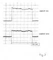
- FIG. 2 shows a diagram of the forces measured by the two force measuring sensors assigned to the servomotors 4 and 5.
- the bearing force is recorded on the left and bottom, the bearing force on the right over time, whereby - due to the approximate rectangular shape of the forces occurring - is clearly visible, that in the time applied, a workpiece 7 has been transported through the printing nip 2.
- the bearing force on the left was significantly higher than the bearing force on the right, which suggests that on average the thickness profile of the workpiece 7 does not harmonize with the setting of the engraving cylinder 3 and the counterpressure roller.
- the higher left bearing force indicates that there the effective radius of the engraving cylinder 3 is lower than on the right side.
- the force measuring sensors record the time course of the left and right bearing forces, as well as with the thickness gauge 9, not only the thickness difference of the workpiece 7 between the right and left sides are measured, but also its thickness profile in throughput direction.
- FIG. 3 and Figure 4 show two different embodiments of a thickness measuring device 9 of the device according to the invention.
- a total of four distance sensors 10 are provided for thickness measurement, seen above the workpiece in the direction of passage 8 on the left side 10a and on the right side 10b and below the workpiece on the left side 10c and on the right side 10d.
- the thickness of the workpiece 7 is measured on the right and left.
- a front edge sensor 11 sets down a signal as soon as the leading edge 7 of the workpiece passes it. With the help of this signal can then - as is well known - the printed image are triggered or optionally the gravure cylinder 3 or arranged between the gravure cylinder and the workpiece 7 blanket cylinder so accelerated or decelerated that the print image start coincides with the front edge of the workpiece 7 and no Edge remains.
- FIG. 4 Another principle of a thickness measurement is shown in FIG. 4: viewed in the direction of passage 8, laterally next to the workpiece, two CCD cameras 12 are arranged, with a left CCD camera 12a scanning the left side edge of the workpiece 7, while a right CCD camera 12b monitors the right side edge of the workpiece 7. Based on the pixels recorded by the CCD cameras 12 and their gray values, the respective thickness of the workpiece 7 guided past the CCD cameras 12 can be determined.
Landscapes
- Engineering & Computer Science (AREA)
- Mechanical Engineering (AREA)
- Life Sciences & Earth Sciences (AREA)
- Wood Science & Technology (AREA)
- Inking, Control Or Cleaning Of Printing Machines (AREA)
- Printing Methods (AREA)
- Delivering By Means Of Belts And Rollers (AREA)
- Screen Printers (AREA)
Abstract
Description
Die Erfindung betrifft ein Verfahren und eine Vorrichtung zum Bedrucken von plattenförmigen Werkstücken nach den Oberbegriffen der Ansprüche 1 und 9. Demnach werden die Werkstücke in einem Druckspalt bedruckt, der von zwei in ihrem Abstand zueinander einstellbaren Druckwalzen gebildet wird. Die plattenförmigen Werkstücke werden hierzu mittels einer Transporteinrichtung zum Druckspalt transportiert. Die den Druckspalt bildenden Druckwalzen können Druckzylinder für den direkten Druck, Auftragswalzen für den indirekten Druck sowie Gegendruckzylinder sein.The invention relates to a method and an apparatus for printing plate-shaped workpieces according to the preambles of
Solche Druckverfahren und entsprechende Vorrichtungen sind seit Langem bekannt. In jüngerer Zeit werden mittels eines solchen Druckverfahrens zunehmend auch Druckbilder von Dekoren und Maserungen auf Holzwerkstoffplatten und dergleichen aufgebracht, um diesen ein Aussehen von Echtholz zu geben. Dies ist nicht nur gegenüber einem Echtholzfurnier, sondern auch gegenüber der seit Längerem gebräuchlichen Folienbeschichtung von Holzwerkstoffplatten kostengünstiger.Such printing methods and corresponding devices have been known for a long time. Recently, by means of such a printing process, printed images of decors and grains are increasingly applied to wood-based panels and the like in order to give them an appearance of real wood. This is not only more cost effective compared to a real wood veneer, but also compared with the film coating of wood-based panels that has been in use for a long time.
Für eine möglichst hohe Qualitätsanmutung reicht allerdings ein einfacher Einfarbendruck nicht aus. Es ist vielmehr erwünscht, die Maserung oder das Dekor im Mehrfarbendruck auf die plattenförmigen Werkstücke aufzubringen. Dies ist durchaus nicht nur bei Holzwerkstoffen der Fall; auch Anwendungen bei anderen Werkstoffen, die durch einen Oberflächendruck qualitativ verbessert werden können, wie beispielsweise Stein oder Kunstleder, oder auch Kunststoffteile, können durch einen Mehrfarbendruck optisch aufgewertet werden.For a high quality impression, however, a simple single-color printing is not enough. Rather, it is desirable to apply the grain or the decoration in multi-color printing on the plate-shaped workpieces. This is certainly not the case only with wood-based panels; also applications with other materials, which can be qualitatively improved by a surface pressure, such as stone or artificial leather, or plastic parts, can be visually upgraded by a multi-color print.
Gerade für einen qualitativ hochwertigen Mehrfarbendruck ist es jedoch unabdingbar, dass das Druckbild auf dem Werkstück innerhalb sehr enger Toleranzen positioniert wird, typischerweise mit Toleranzen von etwa ± 0,1 mm bis ± 0,25 mm. Nur so kann eine mit der herkömmlichen Folienbeschichtung vergleichbare optische Qualität der bedruckten Oberfläche erzielt werden.However, especially for high quality multi-color printing, it is indispensable for the print image to be positioned on the workpiece within very close tolerances, typically with tolerances of about ± 0.1 mm to ± 0.25 mm. Only in this way is it possible to achieve an optical quality of the printed surface that is comparable to conventional film coating.
Diese Anforderungen sind bei den vorliegend verarbeiteten plattenförmigen Werkstücken allerdings ungleich schwerer einzuhalten, als bei herkömmlichen Druckmaschinen für Papier oder Folien. Denn die Werkstücke laufen nicht endlos durch die Druckmaschine, und ein Drucken nach dem Vorbild von Papier-Bogendruckmaschinen ist in aller Regel wegen der Unnachgiebigkeit der betreffenden plattenförmigen Werkstücke nicht möglich. Gleichzeitig sind gerade plattenförmige Werkstücke, die mit Holzmaserungen und Holzdekoren bedruckt werden sollen, bis zu mehreren Quadratmetern groß, ohne dass die beim Druck einzuhaltenden Toleranzen sich ändern würden. Die Anforderungen an die exakte Ausrichtung der am Druck beteiligten Druckwalzen und deren Fertigungstoleranzen sind dementsprechend extrem hoch und in realiter kaum korrekt voreinzustellen.However, these requirements are much harder to comply with the presently processed plate-shaped workpieces, as in conventional printing machines for paper or film. Because the workpieces do not run endlessly through the printing press, and printing on the model of paper sheet printing machines is usually not possible because of the intransigence of the relevant plate-shaped workpieces. At the same time straight plate-shaped workpieces that are to be printed with wood grain and wood decors, up to several square meters in size, without the pressure to be maintained tolerances would change. The requirements for the exact alignment of the pressure rollers involved in the printing and their manufacturing tolerances are accordingly extremely high and hardly preset in realiter.
Erschwerend kommt hinzu, dass bei Druckmaschinen der vorliegenden Art die den Druckspalt bildenden Druckwalzen in ihrem Abstand zueinander einstellbar sind, um plattenförmige Werkstücke unterschiedlicher Dicke bedrucken zu können. Auch hier liegen wiederum völlig andere Verhältnisse vor, wie beim Drucken von Papierbögen und Papierbahnen oder Folien. Das Gegeneinander-Verstellen der Druckwalzen ist kaum in der erforderlichen Parallelität zu schaffen, die auch bei großen Werkstücken und dementsprechend langen Druckwalzen die erwünschte Genauigkeit im Druck gewährleistet. Eine Höhenschränkung der Druckwalzen, also eine Unparallelität in der durch die Druckwalzenachsen aufgespannten Ebene ergibt jedoch beim Druck durch die Nachgiebigkeit der auf der Werkstückoberfläche abrollenden Druckwalze einen über die Breite nicht konstant bleibenden Wirkradius. Beim indirekten Druck und den dort üblicherweise verwendeten Druckwalzen ergibt eine Änderung des Druckwalzen-Wirkradius um lediglich 0,1 mm jedoch schon eine Längenänderung des Druckbildes um etwa 0,6 mm je Abwickellänge der Druckwalze. Dies würde schon weit außerhalb der erwünschten bzw. für einen hochwertigen Mehrfarbendruck erforderlichen Druckbildtoleranzen liegen.To make matters worse, that in printing presses of the present type, the printing gap forming pressure rollers are adjustable in their distance from each other to print plate-shaped workpieces of different thickness can. Again, completely different conditions are present, such as the printing of paper sheets and paper webs or films. The mutual adjustment of the pressure rollers is difficult to create in the required parallelism, which ensures the desired accuracy in printing even with large workpieces and correspondingly long pressure rollers. A height restriction of the pressure rollers, ie a non-parallelism in the plane spanned by the pressure roller axes level results in pressure by the flexibility of rolling on the workpiece surface pressure roller over the width not constant remaining effective radius. In the case of indirect printing and the printing rollers usually used there, however, a change in the printing roller effective radius by only 0.1 mm already results in a change in length of the printed image by about 0.6 mm per unwinding length of the printing cylinder. This would already far beyond the desired or required for a high-quality multi-color printing print tolerances.
Die Parallelität der Druckwalzen muss daher von Hand nachjustiert werden. Hierzu wird ein Blatt Papier in den Druckspalt eingeführt, gegebenenfalls mit einer darin liegenden Platte, und im Druckspalt hin- und herbewegt. Ein erfahrener Drucker kann dann mit dem in der Hand gehaltenen Blatt Papier erfühlen, ob der Druckspalt über seine gesamte Breite parallel ist oder nicht. Diese mit Gespür durchgeführte Messung und das entsprechende Feinjustieren erzielt brauchbare Ergebnisse im Zehntel- bis Hundertstel-mm-Bereich.The parallelism of the pressure rollers must therefore be readjusted by hand. For this purpose, a sheet of paper is introduced into the nip, optionally with a plate therein, and reciprocated in the nip. An experienced printer can then use the hand-held sheet of paper to sense whether or not the nip is parallel across its entire width. This tactile measurement and fine-tuning provides useful results in tenths to hundredths of a millimeter range.
Gleichwohl ist insbesondere bei großflächigen plattenförmigen Werkstücken zu beobachten, dass der Mehrfarbendruck unscharf aussieht und die Platten teilweise sogar beim Durchtritt durch den Druckspalt minimal um die Hochachse gedreht werden.Nevertheless, it can be observed, in particular in the case of large-area plate-shaped workpieces, that the multicolor printing looks blurred and the plates are sometimes even rotated minimally around the vertical axis when they pass through the printing gap.
Der vorliegenden Erfindung liegt daher die Aufgabe zugrunde, ein Verfahren und eine Vorrichtung der eingangs genannten Art vorzuschlagen, die ermöglichen, plattenförmige Werkstücke mit verbesserten Druckbildtoleranzen zu bedrucken.The present invention is therefore based on the object to propose a method and an apparatus of the type mentioned, which allow to print plate-shaped workpieces with improved print image tolerances.
Gelöst ist diese Aufgabe durch ein Verfahren mit den Merkmalen des Anspruchs 1 und durch eine Vorrichtung mit den Merkmalen des Anspruchs 9.This object is achieved by a method having the features of
Bevorzugte Weiterbildungen des Verfahrens sind in den Ansprüchen 2 bis 8 niedergelegt; bevorzugte Ausgestaltungen der erfindungsgemäßen Vorrichtung finden sich in den Ansprüchen 10 bis 16.Preferred embodiments of the method are set forth in
Erfindungsgemäß ist bei der Analyse des Problems der unscharfen Drucke bzw. der zu großen Druckbildtoleranzen trotz exakter Ausrichtung der Druckwalzen von Hand erkannt worden, dass das Hauptproblem in den Dickentoleranzen der plattenförmigen Werkstücke liegt. Insbesondere große Holzwerkstoffplatten haben meist einen leicht keilförmigen Querschnitt, was einer Höhenverschränkung der Druckwalzen im Ergebnis entspricht. Denn die dickere Seite der Holzwerkstoffplatte führt bei parallelen Druckwalzen zu einer Verringerung des Wirkradius der Druckwalze gegenüber der dünneren Seite des Werkstücks, die durchaus 0,1 bis 0,2 mm betragen kann. Wie oben bereits erwähnt, bewirkt dies jedoch eine Längenänderung des Druckbildes je Abwickellänge der Druckwalze um etwa 0,65 bis 1,3 mm. Auch eine leichte Welligkeit oder Keilform des Werkstücks in Längsrichtung beeinflusst die Druckqualität und die Druckbildtoleranzen durch eine jeweils höhere oder niedrigere Andruckhöhe, wodurch einerseits zu hohe Andruckkräfte und andererseits zu niedrigere Andruckkräfte mit schwachem oder verwischtem Druckbild resultieren.According to the invention has been recognized in the analysis of the problem of blurred prints or too large print tolerances despite accurate alignment of the pressure rollers by hand that the main problem lies in the thickness tolerances of the plate-shaped workpieces. In particular, large wood-based panels usually have a slightly wedge-shaped cross section, which corresponds to a height entanglement of the pressure rollers in the result. Because the thicker side of the wood-based panel leads to a reduction in parallel pressure rollers the effective radius of the pressure roller against the thinner side of the workpiece, which may well be 0.1 to 0.2 mm. However, as already mentioned above, this causes a change in length of the printed image per unwinding length of the pressure roller by about 0.65 to 1.3 mm. Even a slight ripple or wedge shape of the workpiece in the longitudinal direction affects the print quality and the image tolerances by a respective higher or lower pressure height, resulting on the one hand too high pressure forces and on the other hand to lower pressure forces with weak or blurred print image.
Aufgrund dieser Erkenntnisse wird erfindungsgemäß vorgeschlagen, vor dem Druckspalt die Dicke eines jeden Werkstücks, gegebenenfalls - wenn vorhanden - mitsamt dem Transportband und dessen toleranzbehafteten Dicke, zu messen und die den Druckspalt bildenden Druckwalzen mittels Stellmotoren an deren Lagern automatisch auf die gemessene Dicke des Werkstücks - gegebenenfalls mit Transportband - einzustellen. Insofern eine über die Breite des Werkstücks unterschiedliche Dicke gemessen wird, beispielsweise eine Keilform, wird der Druckspalt dementsprechend durch Verschränken der beiden Druckwalzen gegeneinander, also durch schiefwinkliges Verändern des Abstandes der beiden Druckwalzen zueinander, auf diese Keilform eingestellt, so dass der Wirkradius der Druckwalze über die gesamte Breite des Werkstücks konstant bleibt und so die erwünschten minimalen Bildtoleranz-Werte erzielt werden können.Based on these findings, the invention proposes to measure before the nip, the thickness of each workpiece, optionally - if present - together with the conveyor belt and its tolerant thickness, and the pressure nip forming pressure rollers by means of actuators at their bearings automatically to the measured thickness of the workpiece - if necessary with conveyor - set. Insofar as a thickness that is different across the width of the workpiece is measured, for example a wedge shape, the press nip is accordingly adjusted to this wedge shape by interleaving the two pressure rollers relative to one another, ie by obliquely changing the distance between the two pressure rollers, so that the effective radius of the pressure roller exceeds the entire width of the workpiece remains constant and so the desired minimum image tolerance values can be achieved.
Das grundlegende Prinzip der vorliegenden Erfindung ist also eine beidseitig vorgesehene, wechselweise unabhängige motorische Druckspaltverstellung in Abhängigkeit von einem zuvor in Linie gemessenen Werkstück-Dickensignal.The basic principle of the present invention is thus provided on both sides, alternately independent motorized pressure gap adjustment as a function of a previously measured in-line workpiece thickness signal.
Sinnvollerweise wird die Dicke des Werkstücks an mindestens zwei Messpunkten gemessen, deren Verbindungsstrecke im Wesentlichen parallel zu den Druckwalzenachsen verläuft. Hierdurch kann eine sehr einfach herzustellende Korrelation der Werkstückdicke mit der Druckspaltverstellung erzielt werden, insbesondere für minimal keilförmige Platten.It makes sense to measure the thickness of the workpiece at at least two measuring points whose connecting path runs essentially parallel to the pressure roller axes. This allows a very easy to produce correlation of the workpiece thickness can be achieved with the pressure gap adjustment, especially for minimal wedge-shaped plates.
Die Dickenmessung kann in Transportrichtung über die gesamte Werkstücklänge erfolgen, so dass ein Dickenprofil gemessen wird, anhand dessen dann der Druckspalt beim Durchtritt des Werkstücks in Echtzeit verstellt werden kann. Diese Maßnahme ermöglicht unabhängig von einer Dickenänderung des Werkstücks über dessen Breite eine Anpassung des Druckspalts bei Dickenänderungen des Werkstücks über dessen Länge. Ideal ist es natürlich, wenn sowohl die Dickentoleranzen in der Breite als auch diejenigen in der Länge des Werkstücks durch entsprechendes Einstellen des Druckspalts kompensiert werden können, um einen exakten Druck auf die Plattenoberfläche aufzubringen.The thickness measurement can take place in the transport direction over the entire workpiece length, so that a thickness profile is measured, by means of which the printing gap can then be adjusted in real time as the workpiece passes. This measure allows regardless of a change in thickness of the workpiece over the width of an adjustment of the pressure nip at changes in thickness of the workpiece over its length. Of course, it is ideal if both the thickness tolerances in the width and those in the length of the workpiece can be compensated for by adjusting the pressure gap to apply an exact pressure to the plate surface.
Ganz besondere Vorteile ergeben sich im Rahmen der vorliegenden Erfindung außerdem, wenn die Einstellung des Druckspalts nicht nur anhand der vor dem Druck erfolgten Dickenmessung durchgeführt wird, sondern auch die beim Druck auf die Druckwalzen und dementsprechend auf deren Lager einwirkenden Kräfte gemessen werden. Denn eine gemessene Differenz der Lagerkräfte gibt einen Hinweis darauf, dass entweder die Druckwalzenoberflächen nicht parallel sind, also eine Höhenschränkung vorliegt, oder dass das gerade bedruckte Werkstück keine parallelen Oberflächen aufweist. In beiden Fällen werden dann die an den Lagern einer Druckwalze vorhandenen Stellmotoren so lange betätigt, bis die Differenz der Lagerkräfte in etwa Null ist oder gegebenenfalls einem gewünschten Offset-Wert entspricht.In the context of the present invention, particular advantages also result if the adjustment of the pressure nip is not only carried out on the basis of the thickness measurement carried out prior to the printing, but also the forces acting upon the pressure rollers and accordingly on their bearings are measured. For a measured difference in the bearing forces gives an indication that either the pressure roller surfaces are not parallel, so there is a height restriction, or that the currently printed workpiece has no parallel surfaces. In both cases, the existing on the bearings of a pressure roller servomotors are then operated until the difference in the bearing forces is approximately zero or optionally corresponds to a desired offset value.
Alternativ oder zusätzlich zur direkten oder indirekten Ansteuerung der Stellmotoren aufgrund der gemessenen Lagerkräfte-Differenz kann eine solche auch dazu benutzt werden, die Korrelation zwischen der vor dem Druck gemessenen Dicke und der Verstellung des Druckspalts zu korrigieren. Denn beispielsweise kann es durchaus der Fall sein, dass durch eine geringe Höhenschränkung der beiden Druckwalzen ein unerwünschter Parallelitäts-Offset besteht, der auch durch ein Verstellen des Druckspalts aufgrund der Dickenmessungen der Werkstücke nicht beseitigt wird. Hier kann die gemessene Differenz der Lagerkräfte ein Korrekturglied generieren.Alternatively, or in addition to the direct or indirect control of the servomotors due to the measured bearing forces difference, such can also be used to correct the correlation between the thickness measured before the pressure and the adjustment of the pressure gap. For example, it may well be the case that there is an undesirable parallelism offset by a small height restriction of the two pressure rollers, which is not eliminated by an adjustment of the pressure gap due to the thickness measurements of the workpieces. Here, the measured difference of the bearing forces can generate a correction element.
Die Verhältnisse in Druckmaschinen der vorliegenden Art sind jedoch komplex, und eine Verstellung des Druckspalts in Echtzeit als Rückmeldung auf entsprechende Messwerte generiert ein schwingungsfähiges System, so dass es vorteilhaft sein kann, die Lagerkräfte und deren Differenz in Zeitintervallen zu mitteln und dann eine mittels eines geeigneten Algorithmus errechnete Tendenzkorrektur durchzuführen. Eine gemessene Lagerkraft-Differenz wirkt sich dann also nicht unmittelbar auf das gerade gemessene Werkstück aus, sondern führt in der Tendenz über mehrere Werkstücke hinweg zu immer besseren Ergebnissen.However, the conditions in printing presses of the present type are complex, and an adjustment of the printing gap in real time in response to corresponding measured values generates a vibratory system, so that it is advantageous may be to average the bearing forces and their difference in time intervals and then perform a trend correction calculated by a suitable algorithm. A measured bearing force difference then does not directly affect the workpiece just measured, but tends to result in better and better results across several workpieces.
Soweit nicht nur der Differenzwert der beiden Lagerkräfte gemessen wird, sondern auch deren Absolutwert, können daraus Rückschlüsse erhalten werden über das Dickenprofil in Längsrichtung des Werkstücks. Beispielsweise bei einer leichten Keilform von Werkstücken nicht nur in der Breite, sondern auch in der Länge, ist der Verlauf der Absolutwerte der gemessenen Lagerkräfte ein Maß für die Keilform des Werkstücks in Längsrichtung, während die Differenz der Lagerkräfte ein Maß für die Keilform in der Breite - unter Berücksichtigung einer etwa vorhandenen Höhenschränkung der beiden Druckwalzen - ist.Insofar as not only the differential value of the two bearing forces is measured, but also their absolute value, conclusions can be obtained about the thickness profile in the longitudinal direction of the workpiece. For example, in a slight wedge shape of workpieces not only in width, but also in length, the course of the absolute values of the measured bearing forces is a measure of the wedge shape of the workpiece in the longitudinal direction, while the difference of the bearing forces is a measure of the wedge shape in width - Taking into account any existing height restriction of the two pressure rollers - is.
Mit der zur erfindungsgemäßen Messung der Werkstückdicke vor Erreichen des Druckspalts vorhandenen Sensorik kann vorteilhafterweise auch die Vorderkante des Werkstücks mit erfasst werden und mit dieser Information das Werkstück und/oder eine beim Druck beteiligte Druckwalze beschleunigt oder verzögert werden, um einen lagegenauen Bildanfang auf dem Werkstück sicherzustellen. Dieses Verfahren ist an sich aus der
Wenn es die geforderte Druckbildtoleranz zulässt, können die beiden Druckwalzen des Druckspalts in einem geringen Maße als Offset-Einstellung gegeneinander verschränkt werden, so dass eine quer zur Transportrichtung des Werkstücks gerichtete Kraft auf dieses einwirkt. Dies kann erwünscht sein, um das Werkstück zuverlässig entlang einer Randbegrenzung, beispielsweise eines Seitenlineals zu führen und bei rechteckigen Platten so einen lagegenauen Durchlauf durch sämtliche Druckspalte einer Mehrfarben-Druckmaschine zu gewährleisten.If it allows the required print image tolerance, the two pressure rollers of the printing nip can be interlocked to a small extent as offset adjustment, so that a transversely directed to the transport direction of the workpiece force acts on this. This may be desirable in order to guide the workpiece reliably along an edge boundary, for example of a side ruler, and thus to ensure a precise pass through all printing gaps of a multicolor printing press in the case of rectangular plates.
Die erfindungsgemäß vorhandene Dickenmesseinrichtung vor dem Druckspalt kann so ausgestaltet werden, dass oberhalb und unterhalb des Werkstücks Abstandssensoren angeordnet sind und über Differenzbildung die Dicke des Werkstücks ermittelt wird.The present invention thickness measuring device in front of the printing nip can be designed so that above and below the workpiece Distance sensors are arranged and the difference of the thickness of the workpiece is determined.
Alternativ hierzu kann die Dickenmesseinrichtung auch aus zwei bildgebenden Sensoren bestehen, die seitlich die beiden Seitenkanten des Werkstücks abtasten und dementsprechend ein Profil desselben aufnehmen.Alternatively, the thickness measuring device may also consist of two imaging sensors which laterally scan the two side edges of the workpiece and accordingly record a profile thereof.
Als weitere Alternative kann die Dickenmesseinrichtung aus einem Messkalander bestehen, der mit Wegsensoren versehen ist, um die Dicke des Werkstücks zu ermitteln. Der große Vorteil eines Messkalanders besteht darin, dass die von diesem gemessenen Werte exakt denjenigen Werten entsprechen, die beim Druckspalt eingestellt werden müssen, auch wenn das Werkstück keine exakte Keilform aufweist, sondern eine gewisse Welligkeit, die durch die Korrektur des Druckspalts nur ausgemittelt werden kann, da die Druckwalzen zylindrisch geformt sind. Als weiterer, nicht zu unterschätzender Vorteil bietet ein Messkalander die Möglichkeit, nicht nur Wegsensoren, sondern auch Kraftsensoren an dessen Lagern anzubringen, um die oben beschriebene Kräftemessung bzw. Kraftdifferenz-Messung schon durchzuführen, bevor das Werkstück den Druckspalt erreicht. Dies eröffnet die Möglichkeit, den Druckspalt noch vor dem Druck anhand einer Kraftdifferenz-Messung zu verstellen.As a further alternative, the thickness gauge may consist of a measuring calender provided with displacement sensors for determining the thickness of the workpiece. The great advantage of a measuring calender is that the values measured by it correspond exactly to those values which have to be set at the printing nip, even if the workpiece does not have an exact wedge shape, but a certain waviness, which can only be averaged out by the correction of the printing nip because the pressure rollers are cylindrically shaped. As a further, not to be underestimated advantage of a Meßkalander offers the possibility not only displacement sensors, but also to attach force sensors to its bearings in order to carry out the above-described force measurement or force difference measurement before the workpiece reaches the nip. This opens up the possibility of adjusting the pressure gap before the pressure by means of a force difference measurement.
Wie eingangs erwähnt, ist die vorliegende Erfindung insbesondere für den Mehrfarbendruck geeignet, so dass vorzugsweise mehrere Druckspalte in Linie hintereinander angeordnet sind. Hier ergibt sich dann durch die Korrekturmöglichkeit aufgrund einer Kräftemessung an allen Druckspalten eine sehr hohe Genauigkeit beim Übereinanderdrucken der verschiedenen Farben, während der werkstückabhängige Korrekturbedarf durch eine einmalige Dickenmessung vor Erreichen des ersten Druckspaltes durchgeführt werden kann. Die Kräftemessung an den Lagern der einzelnen Druckwalzen ist demgegenüber für jeden Druckspalt spezifisch.As mentioned above, the present invention is particularly suitable for multi-color printing, so that preferably a plurality of pressure gaps are arranged in line one behind the other. In this case, due to the possibility of correction due to a force measurement at all printing nips, a very high accuracy results when printing on the different colors, while the workpiece-dependent correction requirement can be carried out by a single thickness measurement before reaching the first printing nip. In contrast, the force measurement at the bearings of the individual pressure rollers is specific for each pressure nip.
Ein Ausführungsbeispiel der vorliegenden Erfindung wird im Folgenden anhand der beigefügten Zeichnungen beschrieben und erläutert. Es zeigen:
Figur 1- eine schematische Draufsicht auf ein Ausführungsbeispiel einer erfindungsgemäßen Druckvorrichtung;
Figur 2- ein Diagramm der Lagerkräfte einer Druckwalze aus Figur 1;
Figur 3- eine schematische Darstellung einer Dickenmesseinrichtung für die in
Figur 1 gezeigte Vorrichtung; Figur 4- eine schematische Darstellung eines anderen Ausführungsbeispiels einer Dickenmesseinrichtung.
- FIG. 1
- a schematic plan view of an embodiment of a printing device according to the invention;
- FIG. 2
- a diagram of the bearing forces of a pressure roller of Figure 1;
- FIG. 3
- a schematic representation of a thickness measuring device for the device shown in Figure 1;
- FIG. 4
- a schematic representation of another embodiment of a thickness measuring device.
In Figur 1 ist in Draufsicht schematisch ein Ausführungsbeispiel für eine erfindungsgemäße Vorrichtung dargestellt. Es handelt sich um eine Druckmaschine für einen einfachen Direkt-Druck bzw. eine erste Druckstation für eine Mehrfarben-Druckmaschine, deren weitere Druckstationen zur Vereinfachung nicht dargestellt sind. Ein Transportband 1 läuft durch einen Druckspalt 2, der durch eine als Gravurzylinder ausgebildete Druckwalze 3 und einen in Draufsicht nicht sichtbaren, unterhalb des Transportbandes 1 angeordneten GegendruckZylinder gebildet ist. Mittels eines linken 4 und eines rechten Stellmotors 5 ist der Gravurzylinder 3 höhenverstellbar, wobei die beiden Stellmotoren 4 und 5 unabhängig voneinander betätigt werden können. Auf einer vorgelagerten Rollenbahn 6 aufliegend wird ein plattenförmiges Werkstück 7 in einer durch den Pfeil 8 symbolisierten Durchlaufrichtung an den Druckspalt 2 herangeführt, wo es an das Transportband 1 übergeben wird. Zuvor passiert es eine Dickenmesseinrichtung 9, die hier aus jeweils zwei oberhalb und unterhalb des Werkstücks 7 angeordnete rechte und linke Abstandssensoren 10 gebildet ist. Dementsprechend wird das Werkstück 7 sowohl an seiner rechten als auch an seiner linken Seite vermessen, um Dickenunterschiede etwa durch eine leichte Keilform zu erkennen. Liegen solche Dickenunterschiede vor, werden der linke Stellmotor 4 und der rechte Stellmotor 5 entsprechend unterschiedlich verstellt, so dass der Gravurzylinder 3 gegen den Gegendruckzylinder leicht verschränkt wird, um die Keilform des Werkstücks 7 nachzuvollziehen. Dementsprechend ist dann beim Druck der wirksame Radius der Gravurzylinders 3 über die gesamte Breite des Werkstücks 7 konstant, so dass keinerlei Bildverzerrungen entstehen. Auch eine seitliche Ablenkung des Werkstücks 7 ist dann im Druckspalt 2 nicht zu befürchten.In Figure 1, an embodiment of a device according to the invention is shown schematically in plan view. It is a printing machine for a simple direct printing or a first printing station for a multi-color printing machine, the other printing stations are not shown for simplicity. A
Die in Figur 1 nur symbolisch dargestellten linken und rechten Stellmotoren 4, 5 sind außerdem mit Kraftmesssensoren versehen, um die auf den Gravurzylinder beim Bedrucken des Werkstücks 7 wirkenden Lagerkräfte direkt oder indirekt zu messen. Eine Differenz der linken und rechten Lagerkräfte bedeutet, dass die Schränkung von Gravurzylinder 3 und Gegendruckzylinder aufgrund eines Offsets oder sonstiger Effekte den Dickenverlauf des Werkstücks 7 über dessen Breite nicht exakt nachvollzieht und daher unerwünschterweise ein Unterschied im Wirkradius des Gravurzylinders 3 von der linken zur rechten Seite des Werkstücks 7 trotz der aufgrund der Dickenmesseinrichtung 9 verstellten Stellmotoren 4 und 5 auftritt. Dies kann dann zur Tendenzkorrektur des Zusammenhangs zwischen den in der Dickenmesseinrichtung 9 aufgenommenen Werten und der Verstellung der Stellmotoren 4 und 5 für die nachfolgenden Werkstücke 7 verwendet werden.The left and
Ein Diagramm der von den beiden, den Stellmotoren 4 und 5 zugeordneten Kraftmesssensoren gemessenen Kräfte zeigt Figur 2. Oben ist die Lagerkraft links und unten die Lagerkraft rechts über der Zeit aufgezeichnet, wobei - aufgrund der annäherenden Rechteckform der auftretenden Kräfte - gut zu erkennen ist, dass in der aufgetragenen Zeit ein Werkstück 7 durch den Druckspalt 2 transportiert worden ist. Im hier gezeigten Fall war die Lagerkraft links deutlich höher als die Lagerkraft rechts, was darauf hindeutet, dass im Mittel der Dickenverlauf des Werkstücks 7 mit der Schränkung des Gravurzylinders 3 und der Gegendruckwalze nicht harmoniert. Die höhere linke Lagerkraft weist daraufhin, dass dort der wirksame Radius des Gravurzylinders 3 geringer ist als auf der rechten Seite.FIG. 2 shows a diagram of the forces measured by the two force measuring sensors assigned to the
Da, wie in Figur 2 dargestellt, die Kraftmesssensoren den zeitlichen Verlauf der linken und rechten Lagerkräfte aufnehmen, kann, wie auch mit der Dickenmesseinrichtung 9, nicht nur der Dickenunterschied des Werkstücks 7 zwischen dessen rechter und linker Seite gemessen werden, sondern auch dessen Dickenprofil in Durchlaufrichtung. Hierdurch ist eine Höhenverstellung der linken und rechten Stellmotoren 4 und 5 beim Durchlauf des Werkstücks 7 durch den Druckspalt 2 anhand des bekannten Dickenprofils in Echtzeit möglich, was die Druckbildtoleranz nochmals verbessert.Since, as shown in Figure 2, the force measuring sensors record the time course of the left and right bearing forces, as well as with the
Figur 3 und Figur 4 zeigen zwei unterschiedliche Ausführungsbeispiele für eine Dickenmesseinrichtung 9 der erfindungsgemäßen Vorrichtung. In Figur 3 sind insgesamt vier Abstandssensoren 10 zur Dickenmessung vorgesehen, und zwar oberhalb des Werkstücks in Durchlaufrichtung 8 gesehen auf der linken Seite 10a und auf der rechten Seite 10b sowie unterhalb des Werkstücks auf der linken Seite 10c und auf der rechten Seite 10d. Jeweils durch Differenzbildung der beiden linken Abstandsensoren 10a und 10c bzw. der beiden rechten Abstandsensoren 10b und 10d wird rechts und links die Dicke des Werkstücks 7 gemessen.Figure 3 and Figure 4 show two different embodiments of a
In Figur 3 zusätzlich zu erkennen ist ein Vorderkantensensor 11, der ein Signal absetzt, sobald die Vorderkante 7 des Werkstücks ihn passiert. Mit Hilfe dieses Signals kann dann - wie an sich bekannt - das Druckbild getriggert werden oder gegebenenfalls der Gravurzylinder 3 oder ein zwischen dem Gravurzylinder und dem Werkstück 7 angeordneter Gummituchzylinder so beschleunigt oder abgebremst werden, dass der Druckbildanfang mit der Vorderkante des Werkstücks 7 zusammenfällt und kein Rand verbleibt.In addition, it can be seen in FIG. 3 that a
In Figur 4 wird ein anderes Prinzip einer Dickenmessung gezeigt: In Durchlaufrichtung 8 gesehen, seitlich neben dem Werkstück, sind zwei CCD-Kameras 12 angeordnet, wobei eine linke CCD-Kamera 12a die linke Seitenkante des Werkstücks 7 abtastet, während eine rechte CCD-Kamera 12b die rechte Seitenkante des Werkstücks 7 überwacht. Anhand der von den CCD-Kameras 12 aufgenommenen Pixeln und deren Grauwerten kann die jeweils an den CCD-Kameras 12 vorbeigeführte Dicke des Werkstücks 7 ermittelt werden.Another principle of a thickness measurement is shown in FIG. 4: viewed in the direction of
Claims (16)
dadurch gekennzeichnet,
dass vor dem oder während des Transports zum Druckspalt die Dicke eines jeden Werkstücks gemessen wird, und dass der Druckspalt vor dem Druckvorgang mittels parallelem oder schiefwinkligen Verändern des Abstands der beiden Druckwalzen zueinander, entsprechend der gemessenen Dicke des Werkstücks eingestellt wird.Method for printing plate-shaped workpieces in a printing nip, which is formed by two pressure rollers which are adjustable with respect to each other, the plate-shaped workpiece being transported on a transport device to the printing nip and printed on passing through the printing nip,
characterized,
in that the thickness of each workpiece is measured prior to or during transport to the printing nip, and that the printing nip is adjusted before printing by means of parallel or oblique changing of the distance of the two pressure rollers from one another according to the measured thickness of the workpiece.
dadurch gekennzeichnet,
dass die Dicke des Werkstücks an mindestens zwei Messpunkten gemessen wird, wobei die Verbindungsstrecke der beiden Messpunkte im Wesentlichen parallel zu den Druckwalzenachsen verläuft.Method according to claim 1,
characterized,
that the thickness of the workpiece is measured at at least two measuring points, wherein the link of the two measurement points is substantially parallel to the pressure roller axes.
dadurch gekennzeichnet,
dass die Messung der Werkstückdicke in Transportrichtung über die gesamte Werkstücklänge erfolgt und hierdurch ein Dickenprofil gemessen wird, wobei der Druckspalt beim Durchtritt des Werkstücks entsprechend dem gemessenen Dickenprofil in Echtzeit eingestellt wird.Method according to one of claims 1 or 2,
characterized,
that the measurement of the thickness of the workpiece is carried out in the transport direction over the entire length of the workpiece, and thereby a thickness profile with the pressure gap during the passage of the workpiece corresponding to the measured thickness profile in real time is set is measured.
dadurch gekennzeichnet,
dass während des Drucks die auf die Lager der Druckwalzen einwirkenden Lagerkräfte gemessen werden, und dass bei einer Differenz der gemessenen Lagerkräfte der Abstand der beiden Druckwalzen zueinander schiefwinklig verändert wird, bis die Differenz der Lagerkräfte in etwa Null oder in etwa gleich einem gewünschten Offset-Wert ist.Method according to at least one of claims 1 to 3,
characterized,
that during the pressure acting on the bearings of the pressure rollers bearing forces are measured and that the distance of the two pressure rollers is changed to one another at an oblique angle with a difference between the measured bearing forces, until the difference of the bearing forces in approximately zero or approximately equal to a desired offset value is.
dadurch gekennzeichnet,
dass während des Drucks die auf die Lager der Druckwalzen einwirkenden Lagerkräfte gemessen werden, und dass eine Differenz der gemessenen Lagerkräfte für die nachfolgend zu bedruckenden Werkstücke als Korrekturwert in die entsprechend der gemessenen Dicke der Werkstücke erfolgende Einstellung des Druckspalts einfließt.Method according to at least one of claims 1 to 4,
characterized,
in that the bearing forces acting on the bearings of the pressure rollers are measured during the printing, and that a difference of the measured bearing forces for the workpieces to be subsequently printed acts as a correction value in the adjustment of the pressure gap according to the measured thickness of the workpieces.
dadurch gekennzeichnet,
dass das Verändern des Abstands der beiden Druckwalzen zueinander entsprechend der gemessenen Lagerkräfte oder das Einfließen als Korrekturwert in die Einstellung des Druckspalts auf der Grundlage von in Zeitintervallen ermittelten Differenzwerten der Lagerkräfte erfolgt, um insgesamt eine Tendenzkorrektur zu erzielen.Method according to one of claims 4 or 5,
characterized,
in that the variation of the spacing of the two pressure rollers relative to one another according to the measured bearing forces or the influence as a correction value in the adjustment of the pressure gap is carried out on the basis of differential values of the bearing forces determined at time intervals in order to achieve overall tendency correction.
dadurch gekennzeichnet,
dass beim Messen der Dicke der Werkstücke gleichzeitig deren Vorderkante erfasst wird, und mit dieser Information das Werkstück und/oder eine bildgebende Druckwalze beschleunigt oder verzögert wird, um einen lagegenauen Bildanfang auf dem Werkstück sicherzustellen.Method according to at least one of claims 1 to 6,
characterized,
that when measuring the thickness of the workpieces at the same time the leading edge is detected, and with this information, the workpiece and / or an imaging pressure roller is accelerated or decelerated to ensure a positionally accurate image on the workpiece.
dadurch gekennzeichnet,
dass die beiden Druckwalzen des Druckspalts als Offset-Einstellung gegeneinander verschränkt werden, so dass eine quer zur Transportrichtung gerichtete Kraft auf die Werkstücke einwirkt, um diese entlang einer Randbegrenzung zu führen.Method according to at least one of claims 1 to 7,
characterized,
that the two pressure rollers of the printing gap are offset from each other as an offset setting, so that a transversely directed to the transport direction Force acts on the workpieces to guide them along a perimeter boundary.
dadurch gekennzeichnet,
dass vor oder an der Transporteinrichtung (1), dem Druckspalt (2) vorgeschaltet, eine Dickenmesseinrichtung (9) zum Erfassen der Dicke der transportierten Werkstücke (7) angeordnet ist, und dass an mindestens einer der beiden den Druckspalt (2) bildenden Druckwalzen (3) beidseits im Bereich von deren Lagern Stellmotoren (4, 5) zum einseitigen und/oder beidseitigen Verändern des Abstands der beiden Druckwalzen (3) zueinander angebracht sind, wobei die Dickenmesseinrichtung (9) und die Stellmotoren (4, 5) mit einer Steuereinheit verknüpft sind, welche so programmiert ist, dass sie entsprechend der gemessenen Dicke des Werkstücks (7) mittels ein- oder beidseitigem Verstellen der Stellmotoren (4, 5) den Druckspalt (2) vor dem Druckvorgang parallel oder schiefwinklig verändert.Apparatus for carrying out the method according to at least one of claims 1 to 8, with two spaced apart adjustable pressure rollers (3) forming a pressure nip (2) for printing a plate-shaped workpiece (7), and a transport device (1) for transporting of the workpiece (7) to the printing nip (2),
characterized,
that connected upstream in front of or on the transport device (1), the printing gap (2), a thickness measuring means (9) for detecting the thickness of the transported workpieces (7) is arranged, and that on at least one of the two the printing gap (2) forming pressure rollers ( 3) on both sides in the region of their bearings servomotors (4, 5) for unilateral and / or two-sided changing the distance between the two pressure rollers (3) are mounted to each other, wherein the thickness gauge (9) and the servo motors (4, 5) with a control unit are linked, which is programmed according to the measured thickness of the workpiece (7) by means of one or two-sided adjustment of the servo motors (4, 5) the printing gap (2) before printing parallel or obliquely.
dadurch gekennzeichnet,
dass die Dickenmesseinrichtung (9) oberhalb und unterhalb des Werkstücks (7) angeordnete Abstandssensoren (10) umfasst.Device according to claim 9,
characterized,
in that the thickness measuring device (9) comprises distance sensors (10) arranged above and below the workpiece (7).
dadurch gekennzeichnet,
dass die Dickenmesseinrichtung (9) mindestens zwei die Seitenkanten des Werkstücks (7) abtastende bildgebende Sensoren (12) umfasst.Device according to claim 9,
characterized,
that the thickness measuring means (9) at least two side edges of the workpiece (7) comprises scanning imaging sensors (12).
dadurch gekennzeichnet,
dass die Dickenmesseinrichtung (9) einen Messkalander mit Weg- und/oder Kraftmesssensoren umfasst.Device according to claim 9,
characterized,
that the thickness measuring means (9) comprises a Messkalander with displacement and / or force measuring sensors.
dadurch gekennzeichnet,
dass die Transporteinrichtung (1) im Wesentlichen aus einem Transportband besteht, das durch den Druckspalt (2) geführt ist.Device according to at least one of claims 9 to 12,
characterized,
that the transport device (1) essentially consists of a conveyor belt, which is guided through the pressure nip (2).
dadurch gekennzeichnet,
dass an den Lagern mindestens einer Druckwalze (3) Kraftmesssensoren zur Detektion der Lagerkräfte angebracht sind, wobei die Kraftmesssensoren mit der Steuereinheit verknüpft sind und wobei die Steuereinheit so programmiert ist, dass bei einer Differenz der von den Kraftmesssensoren gemessenen Lagerkräfte der Abstand der beiden Druckwalzen (3) zueinander schiefwinklig verändert wird, bis die Differenz der Lagerkräfte in etwa Null oder in etwa gleich einem gewünschten Offsetwert ist.Device according to at least one of claims 9 to 13,
characterized,
in that force measuring sensors for detecting the bearing forces are attached to the bearings of at least one pressure roller (3), the force measuring sensors being linked to the control unit and the control unit being programmed such that, given a difference in the bearing forces measured by the force measuring sensors, the distance of the two pressure rollers ( 3) is changed obliquely to each other until the difference of the bearing forces is approximately zero or approximately equal to a desired offset value.
dadurch gekennzeichnet,
dass eine gemessene Differenz der Lagerkräfte für die nachfolgend zu bedruckenden Werkstücke (7) als Korrekturwert in die entsprechend der gemessenen Dicke der Werkstücke (7) erfolgende Einstellung des Druckspalts (2) einfließt.Device according to at least one of claims 9 to 14,
characterized,
in that a measured difference of the bearing forces for the workpieces (7) to be subsequently printed flows as correction value into the adjustment of the pressure gap (2) taking place according to the measured thickness of the workpieces (7).
dadurch gekennzeichnet,
dass mehrere Druckspalte (2) in Linie hintereinander angeordnet sind.Device according to at least one of claims 9 to 15,
characterized,
that a plurality of pressure gaps (2) are arranged in line one behind the other.
Applications Claiming Priority (1)
| Application Number | Priority Date | Filing Date | Title |
|---|---|---|---|
| DE102006016694A DE102006016694B4 (en) | 2006-04-08 | 2006-04-08 | Method and device for printing plate-shaped workpieces |
Publications (3)
| Publication Number | Publication Date |
|---|---|
| EP1842666A2 true EP1842666A2 (en) | 2007-10-10 |
| EP1842666A3 EP1842666A3 (en) | 2011-05-25 |
| EP1842666B1 EP1842666B1 (en) | 2013-03-27 |
Family
ID=38346153
Family Applications (1)
| Application Number | Title | Priority Date | Filing Date |
|---|---|---|---|
| EP07003380A Active EP1842666B1 (en) | 2006-04-08 | 2007-02-17 | Method and device for printing plate-shaped workpieces |
Country Status (7)
| Country | Link |
|---|---|
| US (1) | US20080028960A1 (en) |
| EP (1) | EP1842666B1 (en) |
| CN (1) | CN101049756A (en) |
| BR (1) | BRPI0701351A (en) |
| DE (1) | DE102006016694B4 (en) |
| ES (1) | ES2433375T3 (en) |
| TW (1) | TW200744854A (en) |
Cited By (2)
| Publication number | Priority date | Publication date | Assignee | Title |
|---|---|---|---|---|
| EP2022568A2 (en) * | 2007-08-07 | 2009-02-11 | GE.MA.TA. S.p.A. | Machine for painting and pattern printing on flat rigid panels |
| ITMI20091461A1 (en) * | 2009-08-11 | 2011-02-12 | Agostino Leveni | PRINTING SYSTEM WITH REPRODUCING MICROCINCIDES ROLLER DRAWINGS OR EFFECTS AND THAT COLORING USING ELECTROSTATIC THERMO-DURING POWDERS OR COLORED PIGMENTS PUT IN SUSPENSION IN A LIQUID VEHICLE. |
Families Citing this family (3)
| Publication number | Priority date | Publication date | Assignee | Title |
|---|---|---|---|---|
| CN103057262A (en) * | 2011-10-24 | 2013-04-24 | 致伸科技股份有限公司 | Printing control method used for printing device and printing device |
| CN109230732A (en) * | 2018-08-31 | 2019-01-18 | 江苏中印印务集团有限公司 | Print deviation correcting device |
| KR102422810B1 (en) * | 2021-11-18 | 2022-07-19 | 한국기계연구원 | Printing apparatus and printing pressure controlling method for printing apparatus |
Citations (3)
| Publication number | Priority date | Publication date | Assignee | Title |
|---|---|---|---|---|
| FR676977A (en) | 1929-06-21 | 1930-03-01 | Masa Gmbh Zur Herstellung Kuns | Machine for printing drawings by transport |
| DE581049C (en) | 1933-07-20 | Julius Fischer Maschinenfabrik | Machine for printing boards, panels or the like. | |
| WO2003035398A1 (en) | 2001-10-24 | 2003-05-01 | Nebiolo Printech S.P.A. | An offset printing press |
Family Cites Families (12)
| Publication number | Priority date | Publication date | Assignee | Title |
|---|---|---|---|---|
| GB1544050A (en) * | 1976-06-16 | 1979-04-11 | Fuji Photo Film Co Ltd | Marking apparatus |
| FR2519583A1 (en) * | 1982-01-12 | 1983-07-18 | Smh Alcatel | TRAINING AND PRINTING MECHANISM FOR POSTAGE MACHINE |
| DE3429049A1 (en) * | 1984-08-07 | 1986-02-20 | Robert Bürkle GmbH & Co, 7290 Freudenstadt | Device for coating planar workpieces with materials which are capable of flowing |
| DE3801429C2 (en) * | 1988-01-20 | 1998-05-20 | Siemens Ag | Printing device with adjustable counter pressure roller |
| US5118209A (en) * | 1990-03-30 | 1992-06-02 | Transtechnology Corporation | Print gap optimizer |
| DE4326794C2 (en) * | 1993-08-10 | 1999-03-11 | Kammann Maschf Werner | Method and device for printing flat individual objects |
| DE19949951C2 (en) * | 1999-10-16 | 2003-06-18 | Ltg Mailaender Gmbh | Painting or printing machine and control method therefor |
| JP2002361993A (en) * | 2001-06-07 | 2002-12-18 | Nec Corp | Sealing apparatus |
| WO2004022465A1 (en) * | 2002-08-30 | 2004-03-18 | Fujitsu Limited | Method for detecting corner turndown of paper sheet and program for detecting corner of paper sheet |
| WO2004086150A1 (en) * | 2003-03-26 | 2004-10-07 | Multi Sign A/S | Printing on metal by selective electrostatic powder coating |
| DE10333626A1 (en) * | 2003-07-24 | 2005-02-17 | Robert Bürkle GmbH | Device for printing on flat workpieces |
| DE102004011229A1 (en) * | 2004-03-04 | 2005-09-29 | Theodor Hymmen Holding Gmbh | Method of printing a plate or panel esp. a wooden panel for e.g. wooden flooring or wall panels where the pressure of the print rollers is controlled based on a measured length of a reference image |
-
2006
- 2006-04-08 DE DE102006016694A patent/DE102006016694B4/en not_active Expired - Fee Related
-
2007
- 2007-02-17 EP EP07003380A patent/EP1842666B1/en active Active
- 2007-02-17 ES ES07003380T patent/ES2433375T3/en active Active
- 2007-03-26 TW TW096110302A patent/TW200744854A/en unknown
- 2007-03-27 US US11/691,663 patent/US20080028960A1/en not_active Abandoned
- 2007-04-04 BR BRPI0701351-5A patent/BRPI0701351A/en not_active IP Right Cessation
- 2007-04-06 CN CNA2007100910755A patent/CN101049756A/en active Pending
Patent Citations (3)
| Publication number | Priority date | Publication date | Assignee | Title |
|---|---|---|---|---|
| DE581049C (en) | 1933-07-20 | Julius Fischer Maschinenfabrik | Machine for printing boards, panels or the like. | |
| FR676977A (en) | 1929-06-21 | 1930-03-01 | Masa Gmbh Zur Herstellung Kuns | Machine for printing drawings by transport |
| WO2003035398A1 (en) | 2001-10-24 | 2003-05-01 | Nebiolo Printech S.P.A. | An offset printing press |
Cited By (3)
| Publication number | Priority date | Publication date | Assignee | Title |
|---|---|---|---|---|
| EP2022568A2 (en) * | 2007-08-07 | 2009-02-11 | GE.MA.TA. S.p.A. | Machine for painting and pattern printing on flat rigid panels |
| EP2022568A3 (en) * | 2007-08-07 | 2010-06-30 | GE.MA.TA. S.p.A. | Machine for painting and pattern printing on flat rigid panels |
| ITMI20091461A1 (en) * | 2009-08-11 | 2011-02-12 | Agostino Leveni | PRINTING SYSTEM WITH REPRODUCING MICROCINCIDES ROLLER DRAWINGS OR EFFECTS AND THAT COLORING USING ELECTROSTATIC THERMO-DURING POWDERS OR COLORED PIGMENTS PUT IN SUSPENSION IN A LIQUID VEHICLE. |
Also Published As
| Publication number | Publication date |
|---|---|
| DE102006016694B4 (en) | 2010-10-07 |
| ES2433375T3 (en) | 2013-12-10 |
| US20080028960A1 (en) | 2008-02-07 |
| DE102006016694A1 (en) | 2007-10-18 |
| CN101049756A (en) | 2007-10-10 |
| BRPI0701351A (en) | 2007-12-11 |
| TW200744854A (en) | 2007-12-16 |
| EP1842666B1 (en) | 2013-03-27 |
| EP1842666A3 (en) | 2011-05-25 |
Similar Documents
| Publication | Publication Date | Title |
|---|---|---|
| EP1500504B1 (en) | Apparatus for printing flat articles produced from wood-fibre material | |
| DE102007049670B4 (en) | Method for register correction in a processing machine and processing machine | |
| EP1829685B1 (en) | Film transfer device with variable film sheet guidance | |
| EP2253442B1 (en) | Processing device and process for working a panel-shaped workpiece | |
| EP1842666B1 (en) | Method and device for printing plate-shaped workpieces | |
| EP2763851A2 (en) | Print finishing method and corresponding device | |
| EP1759844B2 (en) | Process for printing correcting | |
| EP3081516B1 (en) | Method and device for producing a safety element | |
| EP1717030B1 (en) | Device for printing flat workpieces | |
| DE102012202503A1 (en) | Method for processing edge of e.g. wooden plate with edge tape, used in furniture and component industry, involves adjusting profile cutter based on detection result of thickness allowance of edge tape in Y-direction | |
| EP1156400A1 (en) | Method and device for adjusting the register to congruent perfecting of a multicolor printing press | |
| DE102006044488B4 (en) | Method for determining a repeat length web tension function on a printing press and control auxiliary device for carrying out | |
| EP3426492B1 (en) | Method for checking the maintenance of register of printed images to be printed on two opposite sides of a printing material | |
| AT15693U1 (en) | ALIGNING A PLATFORM OBJECT | |
| DE10358190A1 (en) | Multi-color image printing machine controlling process, involves controlling speed of rollers to measure feed speed of printing plate, where speed of one roller is controlled with respect to another roller to move plate at constant speed | |
| EP3659950B1 (en) | Substrate processing device with an assembly and method for operating a substrate processing device | |
| DE102009047776B4 (en) | Method and device for measuring a running direction of a substrate web | |
| DE102007021787B4 (en) | Method for controlling a printing machine | |
| DE19954301A1 (en) | Process and plant for the production of at least 4-ply corrugated cardboard | |
| DE102009016727A1 (en) | Transport and aligning system for conveying sheets to process in coating machine, has two drives for goods spaced apart from each other, where inclined position correction of goods takes place by short-term differential speed of drives | |
| EP0504486A1 (en) | Method for multicolour printing in register a web, particularly a thin web | |
| DE102015200148B4 (en) | Method for adapting at least one length of an area to be formed on a plurality of printed sheets of the same size by printing technology | |
| DE10231323B4 (en) | Device for measuring a layer of material webs | |
| EP3867178B1 (en) | Machine that processes a panel-shaped substrate and that has a system, method for set up, and method for the operation of a system | |
| DE19914356C2 (en) | Foil laying system for covering the top or bottom side of carrier boards with foils |
Legal Events
| Date | Code | Title | Description |
|---|---|---|---|
| PUAI | Public reference made under article 153(3) epc to a published international application that has entered the european phase |
Free format text: ORIGINAL CODE: 0009012 |
|
| AK | Designated contracting states |
Kind code of ref document: A2 Designated state(s): AT BE BG CH CY CZ DE DK EE ES FI FR GB GR HU IE IS IT LI LT LU LV MC NL PL PT RO SE SI SK TR |
|
| AX | Request for extension of the european patent |
Extension state: AL BA HR MK YU |
|
| PUAL | Search report despatched |
Free format text: ORIGINAL CODE: 0009013 |
|
| AK | Designated contracting states |
Kind code of ref document: A3 Designated state(s): AT BE BG CH CY CZ DE DK EE ES FI FR GB GR HU IE IS IT LI LT LU LV MC NL PL PT RO SE SI SK TR |
|
| AX | Request for extension of the european patent |
Extension state: AL BA HR MK RS |
|
| 17P | Request for examination filed |
Effective date: 20110726 |
|
| AKX | Designation fees paid |
Designated state(s): DE ES IT |
|
| GRAP | Despatch of communication of intention to grant a patent |
Free format text: ORIGINAL CODE: EPIDOSNIGR1 |
|
| GRAS | Grant fee paid |
Free format text: ORIGINAL CODE: EPIDOSNIGR3 |
|
| GRAA | (expected) grant |
Free format text: ORIGINAL CODE: 0009210 |
|
| AK | Designated contracting states |
Kind code of ref document: B1 Designated state(s): DE ES IT |
|
| REG | Reference to a national code |
Ref country code: DE Ref legal event code: R096 Ref document number: 502007011502 Country of ref document: DE Effective date: 20130523 |
|
| REG | Reference to a national code |
Ref country code: ES Ref legal event code: FG2A Ref document number: 2433375 Country of ref document: ES Kind code of ref document: T3 Effective date: 20131210 |
|
| PLBE | No opposition filed within time limit |
Free format text: ORIGINAL CODE: 0009261 |
|
| STAA | Information on the status of an ep patent application or granted ep patent |
Free format text: STATUS: NO OPPOSITION FILED WITHIN TIME LIMIT |
|
| 26N | No opposition filed |
Effective date: 20140103 |
|
| REG | Reference to a national code |
Ref country code: DE Ref legal event code: R097 Ref document number: 502007011502 Country of ref document: DE Effective date: 20140103 |
|
| PGFP | Annual fee paid to national office [announced via postgrant information from national office to epo] |
Ref country code: IT Payment date: 20230228 Year of fee payment: 17 |
|
| P01 | Opt-out of the competence of the unified patent court (upc) registered |
Effective date: 20230509 |
|
| PGFP | Annual fee paid to national office [announced via postgrant information from national office to epo] |
Ref country code: ES Payment date: 20240319 Year of fee payment: 18 |
|
| PGFP | Annual fee paid to national office [announced via postgrant information from national office to epo] |
Ref country code: DE Payment date: 20240124 Year of fee payment: 18 |