EP1842510A1 - Zwischenwirbelimplantat - Google Patents
Zwischenwirbelimplantat Download PDFInfo
- Publication number
- EP1842510A1 EP1842510A1 EP07004640A EP07004640A EP1842510A1 EP 1842510 A1 EP1842510 A1 EP 1842510A1 EP 07004640 A EP07004640 A EP 07004640A EP 07004640 A EP07004640 A EP 07004640A EP 1842510 A1 EP1842510 A1 EP 1842510A1
- Authority
- EP
- European Patent Office
- Prior art keywords
- implant according
- anchoring
- anchoring sections
- sections
- parts
- Prior art date
- Legal status (The legal status is an assumption and is not a legal conclusion. Google has not performed a legal analysis and makes no representation as to the accuracy of the status listed.)
- Granted
Links
Images




Classifications
-
- A—HUMAN NECESSITIES
- A61—MEDICAL OR VETERINARY SCIENCE; HYGIENE
- A61F—FILTERS IMPLANTABLE INTO BLOOD VESSELS; PROSTHESES; DEVICES PROVIDING PATENCY TO, OR PREVENTING COLLAPSING OF, TUBULAR STRUCTURES OF THE BODY, e.g. STENTS; ORTHOPAEDIC, NURSING OR CONTRACEPTIVE DEVICES; FOMENTATION; TREATMENT OR PROTECTION OF EYES OR EARS; BANDAGES, DRESSINGS OR ABSORBENT PADS; FIRST-AID KITS
- A61F2/00—Filters implantable into blood vessels; Prostheses, i.e. artificial substitutes or replacements for parts of the body; Appliances for connecting them with the body; Devices providing patency to, or preventing collapsing of, tubular structures of the body, e.g. stents
- A61F2/02—Prostheses implantable into the body
- A61F2/30—Joints
- A61F2/44—Joints for the spine, e.g. vertebrae, spinal discs
- A61F2/442—Intervertebral or spinal discs, e.g. resilient
-
- A—HUMAN NECESSITIES
- A61—MEDICAL OR VETERINARY SCIENCE; HYGIENE
- A61F—FILTERS IMPLANTABLE INTO BLOOD VESSELS; PROSTHESES; DEVICES PROVIDING PATENCY TO, OR PREVENTING COLLAPSING OF, TUBULAR STRUCTURES OF THE BODY, e.g. STENTS; ORTHOPAEDIC, NURSING OR CONTRACEPTIVE DEVICES; FOMENTATION; TREATMENT OR PROTECTION OF EYES OR EARS; BANDAGES, DRESSINGS OR ABSORBENT PADS; FIRST-AID KITS
- A61F2/00—Filters implantable into blood vessels; Prostheses, i.e. artificial substitutes or replacements for parts of the body; Appliances for connecting them with the body; Devices providing patency to, or preventing collapsing of, tubular structures of the body, e.g. stents
- A61F2/02—Prostheses implantable into the body
- A61F2/30—Joints
- A61F2002/30001—Additional features of subject-matter classified in A61F2/28, A61F2/30 and subgroups thereof
- A61F2002/30003—Material related properties of the prosthesis or of a coating on the prosthesis
- A61F2002/3006—Properties of materials and coating materials
- A61F2002/30072—Coating made of plastically deformable or self-moulding material
-
- A—HUMAN NECESSITIES
- A61—MEDICAL OR VETERINARY SCIENCE; HYGIENE
- A61F—FILTERS IMPLANTABLE INTO BLOOD VESSELS; PROSTHESES; DEVICES PROVIDING PATENCY TO, OR PREVENTING COLLAPSING OF, TUBULAR STRUCTURES OF THE BODY, e.g. STENTS; ORTHOPAEDIC, NURSING OR CONTRACEPTIVE DEVICES; FOMENTATION; TREATMENT OR PROTECTION OF EYES OR EARS; BANDAGES, DRESSINGS OR ABSORBENT PADS; FIRST-AID KITS
- A61F2/00—Filters implantable into blood vessels; Prostheses, i.e. artificial substitutes or replacements for parts of the body; Appliances for connecting them with the body; Devices providing patency to, or preventing collapsing of, tubular structures of the body, e.g. stents
- A61F2/02—Prostheses implantable into the body
- A61F2/30—Joints
- A61F2002/30001—Additional features of subject-matter classified in A61F2/28, A61F2/30 and subgroups thereof
- A61F2002/30003—Material related properties of the prosthesis or of a coating on the prosthesis
- A61F2002/3006—Properties of materials and coating materials
- A61F2002/30075—Properties of materials and coating materials swellable, e.g. when wetted
-
- A—HUMAN NECESSITIES
- A61—MEDICAL OR VETERINARY SCIENCE; HYGIENE
- A61F—FILTERS IMPLANTABLE INTO BLOOD VESSELS; PROSTHESES; DEVICES PROVIDING PATENCY TO, OR PREVENTING COLLAPSING OF, TUBULAR STRUCTURES OF THE BODY, e.g. STENTS; ORTHOPAEDIC, NURSING OR CONTRACEPTIVE DEVICES; FOMENTATION; TREATMENT OR PROTECTION OF EYES OR EARS; BANDAGES, DRESSINGS OR ABSORBENT PADS; FIRST-AID KITS
- A61F2/00—Filters implantable into blood vessels; Prostheses, i.e. artificial substitutes or replacements for parts of the body; Appliances for connecting them with the body; Devices providing patency to, or preventing collapsing of, tubular structures of the body, e.g. stents
- A61F2/02—Prostheses implantable into the body
- A61F2/30—Joints
- A61F2002/30001—Additional features of subject-matter classified in A61F2/28, A61F2/30 and subgroups thereof
- A61F2002/30108—Shapes
- A61F2002/3011—Cross-sections or two-dimensional shapes
- A61F2002/30138—Convex polygonal shapes
- A61F2002/30153—Convex polygonal shapes rectangular
-
- A—HUMAN NECESSITIES
- A61—MEDICAL OR VETERINARY SCIENCE; HYGIENE
- A61F—FILTERS IMPLANTABLE INTO BLOOD VESSELS; PROSTHESES; DEVICES PROVIDING PATENCY TO, OR PREVENTING COLLAPSING OF, TUBULAR STRUCTURES OF THE BODY, e.g. STENTS; ORTHOPAEDIC, NURSING OR CONTRACEPTIVE DEVICES; FOMENTATION; TREATMENT OR PROTECTION OF EYES OR EARS; BANDAGES, DRESSINGS OR ABSORBENT PADS; FIRST-AID KITS
- A61F2/00—Filters implantable into blood vessels; Prostheses, i.e. artificial substitutes or replacements for parts of the body; Appliances for connecting them with the body; Devices providing patency to, or preventing collapsing of, tubular structures of the body, e.g. stents
- A61F2/02—Prostheses implantable into the body
- A61F2/30—Joints
- A61F2002/30001—Additional features of subject-matter classified in A61F2/28, A61F2/30 and subgroups thereof
- A61F2002/30316—The prosthesis having different structural features at different locations within the same prosthesis; Connections between prosthetic parts; Special structural features of bone or joint prostheses not otherwise provided for
- A61F2002/30329—Connections or couplings between prosthetic parts, e.g. between modular parts; Connecting elements
-
- A—HUMAN NECESSITIES
- A61—MEDICAL OR VETERINARY SCIENCE; HYGIENE
- A61F—FILTERS IMPLANTABLE INTO BLOOD VESSELS; PROSTHESES; DEVICES PROVIDING PATENCY TO, OR PREVENTING COLLAPSING OF, TUBULAR STRUCTURES OF THE BODY, e.g. STENTS; ORTHOPAEDIC, NURSING OR CONTRACEPTIVE DEVICES; FOMENTATION; TREATMENT OR PROTECTION OF EYES OR EARS; BANDAGES, DRESSINGS OR ABSORBENT PADS; FIRST-AID KITS
- A61F2/00—Filters implantable into blood vessels; Prostheses, i.e. artificial substitutes or replacements for parts of the body; Appliances for connecting them with the body; Devices providing patency to, or preventing collapsing of, tubular structures of the body, e.g. stents
- A61F2/02—Prostheses implantable into the body
- A61F2/30—Joints
- A61F2002/30001—Additional features of subject-matter classified in A61F2/28, A61F2/30 and subgroups thereof
- A61F2002/30316—The prosthesis having different structural features at different locations within the same prosthesis; Connections between prosthetic parts; Special structural features of bone or joint prostheses not otherwise provided for
- A61F2002/30329—Connections or couplings between prosthetic parts, e.g. between modular parts; Connecting elements
- A61F2002/30405—Connections or couplings between prosthetic parts, e.g. between modular parts; Connecting elements made by screwing complementary threads machined on the parts themselves
-
- A—HUMAN NECESSITIES
- A61—MEDICAL OR VETERINARY SCIENCE; HYGIENE
- A61F—FILTERS IMPLANTABLE INTO BLOOD VESSELS; PROSTHESES; DEVICES PROVIDING PATENCY TO, OR PREVENTING COLLAPSING OF, TUBULAR STRUCTURES OF THE BODY, e.g. STENTS; ORTHOPAEDIC, NURSING OR CONTRACEPTIVE DEVICES; FOMENTATION; TREATMENT OR PROTECTION OF EYES OR EARS; BANDAGES, DRESSINGS OR ABSORBENT PADS; FIRST-AID KITS
- A61F2/00—Filters implantable into blood vessels; Prostheses, i.e. artificial substitutes or replacements for parts of the body; Appliances for connecting them with the body; Devices providing patency to, or preventing collapsing of, tubular structures of the body, e.g. stents
- A61F2/02—Prostheses implantable into the body
- A61F2/30—Joints
- A61F2002/30001—Additional features of subject-matter classified in A61F2/28, A61F2/30 and subgroups thereof
- A61F2002/30316—The prosthesis having different structural features at different locations within the same prosthesis; Connections between prosthetic parts; Special structural features of bone or joint prostheses not otherwise provided for
- A61F2002/30329—Connections or couplings between prosthetic parts, e.g. between modular parts; Connecting elements
- A61F2002/30476—Connections or couplings between prosthetic parts, e.g. between modular parts; Connecting elements locked by an additional locking mechanism
- A61F2002/30485—Connections or couplings between prosthetic parts, e.g. between modular parts; Connecting elements locked by an additional locking mechanism plastically deformable
-
- A—HUMAN NECESSITIES
- A61—MEDICAL OR VETERINARY SCIENCE; HYGIENE
- A61F—FILTERS IMPLANTABLE INTO BLOOD VESSELS; PROSTHESES; DEVICES PROVIDING PATENCY TO, OR PREVENTING COLLAPSING OF, TUBULAR STRUCTURES OF THE BODY, e.g. STENTS; ORTHOPAEDIC, NURSING OR CONTRACEPTIVE DEVICES; FOMENTATION; TREATMENT OR PROTECTION OF EYES OR EARS; BANDAGES, DRESSINGS OR ABSORBENT PADS; FIRST-AID KITS
- A61F2/00—Filters implantable into blood vessels; Prostheses, i.e. artificial substitutes or replacements for parts of the body; Appliances for connecting them with the body; Devices providing patency to, or preventing collapsing of, tubular structures of the body, e.g. stents
- A61F2/02—Prostheses implantable into the body
- A61F2/30—Joints
- A61F2/30767—Special external or bone-contacting surface, e.g. coating for improving bone ingrowth
- A61F2/30771—Special external or bone-contacting surface, e.g. coating for improving bone ingrowth applied in original prostheses, e.g. holes or grooves
- A61F2002/30772—Apertures or holes, e.g. of circular cross section
- A61F2002/30774—Apertures or holes, e.g. of circular cross section internally-threaded
-
- A—HUMAN NECESSITIES
- A61—MEDICAL OR VETERINARY SCIENCE; HYGIENE
- A61F—FILTERS IMPLANTABLE INTO BLOOD VESSELS; PROSTHESES; DEVICES PROVIDING PATENCY TO, OR PREVENTING COLLAPSING OF, TUBULAR STRUCTURES OF THE BODY, e.g. STENTS; ORTHOPAEDIC, NURSING OR CONTRACEPTIVE DEVICES; FOMENTATION; TREATMENT OR PROTECTION OF EYES OR EARS; BANDAGES, DRESSINGS OR ABSORBENT PADS; FIRST-AID KITS
- A61F2210/00—Particular material properties of prostheses classified in groups A61F2/00 - A61F2/26 or A61F2/82 or A61F9/00 or A61F11/00 or subgroups thereof
- A61F2210/0061—Particular material properties of prostheses classified in groups A61F2/00 - A61F2/26 or A61F2/82 or A61F9/00 or A61F11/00 or subgroups thereof swellable
-
- A—HUMAN NECESSITIES
- A61—MEDICAL OR VETERINARY SCIENCE; HYGIENE
- A61F—FILTERS IMPLANTABLE INTO BLOOD VESSELS; PROSTHESES; DEVICES PROVIDING PATENCY TO, OR PREVENTING COLLAPSING OF, TUBULAR STRUCTURES OF THE BODY, e.g. STENTS; ORTHOPAEDIC, NURSING OR CONTRACEPTIVE DEVICES; FOMENTATION; TREATMENT OR PROTECTION OF EYES OR EARS; BANDAGES, DRESSINGS OR ABSORBENT PADS; FIRST-AID KITS
- A61F2220/00—Fixations or connections for prostheses classified in groups A61F2/00 - A61F2/26 or A61F2/82 or A61F9/00 or A61F11/00 or subgroups thereof
- A61F2220/0025—Connections or couplings between prosthetic parts, e.g. between modular parts; Connecting elements
-
- A—HUMAN NECESSITIES
- A61—MEDICAL OR VETERINARY SCIENCE; HYGIENE
- A61F—FILTERS IMPLANTABLE INTO BLOOD VESSELS; PROSTHESES; DEVICES PROVIDING PATENCY TO, OR PREVENTING COLLAPSING OF, TUBULAR STRUCTURES OF THE BODY, e.g. STENTS; ORTHOPAEDIC, NURSING OR CONTRACEPTIVE DEVICES; FOMENTATION; TREATMENT OR PROTECTION OF EYES OR EARS; BANDAGES, DRESSINGS OR ABSORBENT PADS; FIRST-AID KITS
- A61F2230/00—Geometry of prostheses classified in groups A61F2/00 - A61F2/26 or A61F2/82 or A61F9/00 or A61F11/00 or subgroups thereof
- A61F2230/0002—Two-dimensional shapes, e.g. cross-sections
- A61F2230/0017—Angular shapes
- A61F2230/0019—Angular shapes rectangular
-
- A—HUMAN NECESSITIES
- A61—MEDICAL OR VETERINARY SCIENCE; HYGIENE
- A61F—FILTERS IMPLANTABLE INTO BLOOD VESSELS; PROSTHESES; DEVICES PROVIDING PATENCY TO, OR PREVENTING COLLAPSING OF, TUBULAR STRUCTURES OF THE BODY, e.g. STENTS; ORTHOPAEDIC, NURSING OR CONTRACEPTIVE DEVICES; FOMENTATION; TREATMENT OR PROTECTION OF EYES OR EARS; BANDAGES, DRESSINGS OR ABSORBENT PADS; FIRST-AID KITS
- A61F2310/00—Prostheses classified in A61F2/28 or A61F2/30 - A61F2/44 being constructed from or coated with a particular material
- A61F2310/00005—The prosthesis being constructed from a particular material
- A61F2310/00011—Metals or alloys
- A61F2310/00023—Titanium or titanium-based alloys, e.g. Ti-Ni alloys
Definitions
- the invention relates to an intervertebral implant having at least one abutment element having a vertebral body contact surface and having a swellable core which is connected to the abutment element on the side remote from the vertebral body abutment surface, the abutment element comprising a support on one side of which the vertebral body Abutment surface is arranged and carries projections on its other side, which are enclosed by the material of the core.
- intervertebral implants which have a arranged between two end plates made of metal or plastic hydrogel core.
- This hydrogel core consists of a swellable material, which can increase its volume by absorbing water and therefore has a certain structural similarity to a natural disc.
- the permanent connection between such a core of a relatively soft material on the one hand and the end plates of a rigid material on the other hand is difficult to accomplish. It is known, for example, to allow the swellable material to migrate into a porous structure of the end plates ( US 5,314,478 ), but this is only possible if the end plates have a corresponding porous structure.
- problems may arise in that the porous structure is filled by the swellable material to the extent that the ingrowth of bone substance is hindered in the porous structure.
- intervertebral bodies are also known in which soft core materials are connected by projections to the end plates, these projections are formed as ribs or strips ( US 5,674,294 ) or as a screw-in plate ( EP 0317972 A1 ).
- the connection takes place only in a partial region of the contact surface between the core material and the material of the end plates or contact elements.
- an intervertebral implant of the type described above in that the projections have elongated thread-like or rod-shaped anchoring sections, which extend at a distance from the carrier and are freely accessible on all sides.
- the soft material surrounds these thread- or rod-shaped sections on all sides due to their universally free accessibility, the anchoring sections are thus completely embedded in the softer material and thus form an intermediate link between the carrier and the core material that connects these materials permanently and very firmly together.
- the anchoring portions preferably extend substantially parallel to the vertebral body abutment surface and spaced from the side of the carrier remote from the vertebral body abutment so that a closed layer of the softer core material may be disposed between the anchoring portions and the carrier.
- the anchoring is therefore not limited to certain areas of the contact surface.
- crossing anchoring sections can form a net-like structure, ie a structure in the manner of a woven or knitted fabric.
- the carrier has frame-shaped side parts on which the anchoring sections are held.
- the anchoring sections are then practically stretched between these side parts, this is especially true when using flat, net-like structures.
- the anchoring parts can, for example, dip into holes in the frame-shaped side parts and be fixed in these. To fix the anchoring parts can be screwed into the holes.
- the anchoring parts are defined via thickening or knots on the outside of the side parts in the holes.
- the anchoring parts consist of swellable material and enclose projections and recesses when swelling in the holes. When receiving water thus results in a positive fixing of the anchoring parts in the holes.
- the anchoring portions are U-shaped with two transverse to the straps and the anchoring sections on the carrier defining legs and a web connecting them.
- the bridge normally runs essentially in a plane which is parallel to the vertebral body bearing surface and spaced from the carrier, in particular the legs and the bridge can be substantially rectilinear.
- anchoring sections may be formed from a single thread-like or rod-shaped component, which forms a larger number of anchoring sections formed in a U-shape by corresponding bends or bends.
- crossing anchoring parts form a planar component which is connected at its edges to the carrier.
- the planar component forms an automatically manageable component, which is connected as such to the carrier.
- the side surfaces in the region of the bandage have a circumferential groove for receiving the edges of the planar component.
- the anchoring portions may either be embedded in the material of the core from the beginning, and this composite material is then connected as a whole to the carrier, or it is provided that the anchoring portions are connected to the carrier and then placed on the anchoring portions of the core material is, which surrounds the anchoring sections when swelling, ie when taking up liquid.
- anchoring sections are designed as pliable, ie as bendable threads or wires.
- the anchoring portions may be made of metal, preferably titanium or a titanium alloy.
- the anchoring sections are coated with a swellable material, so that when enclosing these anchoring sections an intimate connection between the anchoring sections and the surrounding core material takes place.
- the anchoring sections it would also be possible to manufacture the anchoring sections completely from a swellable material, so that when the material swells, the anchoring sections and the surrounding core material join together particularly well.
- the anchoring portions may also consist of a hydrophobic polymer, for example of a stretched polyethylene, which in a particularly preferred form with a hydrophilic, water-swellable, but not soluble polymer is coated.
- the anchoring sections consist of a hydrogel or a xerogel.
- an intervertebral implant 1 is arranged in the intervertebral space 2 between two adjacent vertebral bodies 3, 4. It comprises a lower end plate 5 and an upper end plate 6 and a core 7 arranged between these two end plates 5 and 6.
- the two end plates 5, 6 are mirror images of each other, therefore, only the lower end plate 5 will be described below.
- the end plate 5 with the upwardly projecting edge 9 consists of a bending-resistant and dimensionally stable, biocompatible material, for example of titanium or a titanium alloy or even of a thermoplastic material, for example of polyetheretherketone.
- the end plate 5 is formed substantially rectangular with rounded corners and adapted in size of the cross-sectional area of the vertebral bodies 3, 4, so that substantially the entire intervertebral space is covered by the end plates.
- a larger number of transverse to the longitudinal direction of the edge 9 holes 11 are arranged in the upwardly projecting edge 9, which are designed in the illustrated embodiment as a continuous internal threaded holes.
- the ends of thread or wire-shaped anchoring sections 12 dive, extending in this way across the entire interior 10.
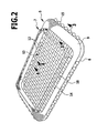
- the anchoring portions 12 of respective opposite parts of the edge 9 are parallel to each other, and the anchoring portions 12 of the mutually perpendicular portions of the edge 9 are accordingly perpendicular to each other, that is, they intersect and thus form a reticulated anchoring surface 13. This extends parallel to the end plate 5 at a distance from the top 14 and in the interior 10. In this case, the entire interior is uniformly covered by the anchoring sections 12, as can be seen from the illustration of Figure 2.
- the anchoring portions 12 are connected with their dipping into the holes 11 ends fixed to the edge 9.
- the anchoring portions 12 may have a coating of swellable material which increases its volume under water absorption. It may be only the sheath, but it may also be provided that the anchoring portion is made entirely of such a material.
- the ends of this way trained anchoring sections 12 are arranged in the region of the edge 9 in an internally threaded bore. Before swelling of the swellable casing, the swellable material does not enter into the threads of the internally threaded bore due to its small volume (FIG. 3 a), that is, the outer diameter of the anchoring sections corresponds to the smallest inner diameter of the internally threaded bore, so that the anchoring sections can be inserted into the internally threaded bore.
- the determination of the anchoring portions 12 in the edge 9 can also be exclusively or additionally by thickening 15, which rest on the outside of the edge 9 and the anchoring portions 12 span between the opposite parts of the frame 9.
- the core consists of a swellable hydrogel, a material that can increase its volume under fluid intake.
- the swellable material of the core 7 increases in fluid intake, that is, after implantation in the intervertebral space 2, its volume, and it encloses the material of the core 7, the anchoring portions 12 of the anchoring surface 13 on all sides, that is, the entire interior 10 of the two end plates 5, 6 is completely filled, as shown in Figure 5.
- the anchoring sections 12 are embedded in the material of the core 7 and thus a toothed connection of the core with the adjacent end plates.
- anchoring sections 12 which in turn are coated with a polymer
- it may be the same polymeric material, as in the material of the core, but it can also be used different polymeric materials that intimately cross-linked with each other received.
- the anchoring portions 12 are in the form of a net-like anchoring surface 13.
Landscapes
- Health & Medical Sciences (AREA)
- Engineering & Computer Science (AREA)
- Biomedical Technology (AREA)
- Neurology (AREA)
- Orthopedic Medicine & Surgery (AREA)
- Cardiology (AREA)
- Oral & Maxillofacial Surgery (AREA)
- Transplantation (AREA)
- Heart & Thoracic Surgery (AREA)
- Vascular Medicine (AREA)
- Life Sciences & Earth Sciences (AREA)
- Animal Behavior & Ethology (AREA)
- General Health & Medical Sciences (AREA)
- Public Health (AREA)
- Veterinary Medicine (AREA)
- Prostheses (AREA)
- Slide Fasteners, Snap Fasteners, And Hook Fasteners (AREA)
Abstract
Description
- Die Erfindung betrifft ein Zwischenwirbelimplantat mit mindestens einem eine Wirbelkörper-Anlagefläche aufweisenden Anlageelement und mit einem quellfähigen Kern, der auf der von der Wirbelkörper-Anlagefläche abgewandten Seite mit dem Anlageelement verbunden ist, wobei das Anlageelement einen Träger umfaßt, auf dessen einer Seite die Wirbelkörper-Anlagefläche angeordnet ist und der auf seiner anderen Seite Vorsprünge trägt, die von dem Material des Kerns umschlossen werden.
- Für die Rekonstruktion der Bandscheibe werden Zwischenwirbelimplantate eingesetzt, die einen zwischen zwei Endplatten aus Metall oder Kunststoff angeordneten Hydrogelkern aufweisen. Dieser Hydrogelkern besteht aus einem quellfähigen Material, das unter Aufnahme von Wasser sein Volumen vergrößern kann und daher eine gewisse strukturelle Ähnlichkeit zu einer natürlichen Bandscheibe aufweist. Die dauerhafte Verbindung zwischen einem solchen Kern aus einem relativ weichen Material einerseits und den Endplatten aus einem starren Material andererseits ist schwierig zu bewerkstelligen. Es ist beispielsweise bekannt, das quellfähige Material in eine poröse Struktur der Endplatten einwandern zu lassen (
US 5,314,478 ), dies ist jedoch nur dann möglich, wenn die Endplatten eine entsprechende poröse Struktur aufweisen. Außerdem können sich dabei Probleme dadurch ergeben, daß die poröse Struktur durch das quellfähige Material soweit ausgefüllt wird, daß das Einwachsen von Knochensubstanz in die poröse Struktur behindert wird. - Es sind auch Konstruktionen von Zwischenwirbelkörpern bekannt, bei denen weiche Kernmaterialien über Vorsprünge mit den Endplatten verbunden werden, diese Vorsprünge sind dabei als Rippen oder Leisten ausgebildet (
US 5,674,294 ) oder als einschraubbare Teller (EP 0317972 A1 ). Die Verbindung erfolgt dabei nur immer in einem Teilbereich der Kontaktfläche zwischen Kernmaterial und dem Material der Endplatten oder Anlageelemente. - Es ist Aufgabe der Erfindung, ein gattungsgemäßes Zwischenwirbelimplantat so zu verbessern, daß der Kontakt zwischen einem weicheren Kernmaterial einerseits und einem daran anliegenden Anlageelement des Zwischenwirbelimplantats andererseits verbessert wird.
- Diese Aufgabe wird bei einem Zwischenwirbelimplantat der eingangs beschriebenen Art erfindungsgemäß dadurch gelöst, daß die Vorsprünge längliche faden- oder stabförmige Verankerungsabschnitte aufweisen, die im Abstand vom Träger verlaufen und allseits frei zugänglich sind. Das weiche Material umgibt diese faden- oder stabförmigen Abschnitte aufgrund ihrer allseits freien Zugänglichkeit allseitig, die Verankerungsabschnitte sind also vollständig in das weichere Material eingebettet und bilden so ein Zwischenglied zwischen dem Träger und dem Kernmaterial, das diese Materialien dauerhaft und sehr fest miteinander verbindet.
- Die Verankerungsabschnitte verlaufen vorzugsweise im wesentlichen parallel zur Wirbelkörper-Anlagefläche und im Abstand von der der Wirbelkörper-Anlagefläche abgewandten Seite des Trägers, so daß zwischen den Verankerungsabschnitten und dem Träger eine geschlossene Schicht des weicheren Kernmaterials angeordnet sein kann.
- Besonders vorteilhaft ist es, wenn im wesentlichen die gesamte Fläche des Trägers Verankerungsabschnitte aufweist. Es kann dann eine Verbindung zwischen dem Träger einerseits und dem Kernmaterial andererseits über die gesamte Kontaktfläche der beiden Materialien hergestellt werden, die Verankerung wird also nicht nur auf bestimmte Bereiche der Kontaktfläche beschränkt.
- Mehrere Verankerungsabschnitte können parallel zueinander verlaufen.
- Bei einer besonders bevorzugten Ausführungsform ist vorgesehen, daß sich verschiedene Verankerungsabschnitte überkreuzen.
- Insbesondere können sich überkreuzende Verankerungsabschnitte eine netzförmige Struktur ausbilden, also eine Struktur nach Art eines Gewebes oder Gewirkes.
- Besonders vorteilhaft ist es, wenn der Träger rahmenförmige Seitenteile aufweist, an denen die Verankerungsabschnitte gehalten sind. Die Verankerungsabschnitte sind dann zwischen diesen Seitenteilen praktisch aufgespannt, dies gilt insbesondere bei Verwendung von flächigen, netzförmigen Strukturen.
- Die Verankerungsteile können beispielsweise in Bohrungen der rahmenförmigen Seitenteile eintauchen und in diesen festgelegt sein. Zur Festlegung können die Verankerungsteile in die Bohrungen eingeschraubt sein.
- Bei einer anderen Ausführungsform ist vorgesehen, daß die Verankerungsteile über Verdickungen oder Knoten an der Außenseite der Seitenteile in den Bohrungen festgelegt sind.
- Bei einer weiteren Ausführungsform bestehen die Verankerungsteile aus quellfähigem Material und umschließen beim Quellen Vorsprünge und Rücksprünge in den Bohrungen. Bei Aufnahme von Wasser ergibt sich somit eine formschlüssige Festlegung der Verankerungsteile in den Bohrungen.
- Bei einer weiteren bevorzugten Ausführungsform sind die Verankerungsabschnitte U-förmig ausgebildet mit zwei quer zu den Trägern verlaufenden und die Verankerungsabschnitte am Träger festlegenden Schenkeln und einem diese verbindenden Steg. Bei diesen Verankerungsabschnitten läuft der Steg normalerweise im wesentlichen in einer Ebene, die parallel zur Wirbelkörper-Anlagefläche und im Abstand vom Träger angeordnet ist, insbesondere können die Schenkel und der Steg im wesentlichen geradlinig verlaufen.
- Es ist dabei günstig, wenn die Schenkel in Bohrungen im Träger eintauchen und in diesen festgelegt sind.
- Mehrere benachbarte Verankerungsabschnitte können aus einem einzigen faden- oder stabförmigen Bauteil gebildet sein, das durch entsprechende Abbiegungen oder Abwinklungen eine größere Anzahl von U-förmig ausgebildeten Verankerungsabschnitten ausbildet.
- Besonders vorteilhaft ist es, wenn sich überkreuzende Verankerungsteile ein flächiges Bauelement ausbilden, das an seinen Rändern mit dem Träger verbunden ist. In diesem Falle bildet das flächige Bauelement ein selbsttätig handhabbares Bauteil, das als solches mit dem Träger verbunden wird.
- Zur Verbindung kann der Träger an seinen Seitenflächen eine umlaufende Bandage tragen, die die Ränder des flächigen Bauteils gegen die Seitenflächen spannt.
- Es ist dabei vorteilhaft, wenn die Seitenflächen im Bereich der Bandage eine umlaufende Nut zur Aufnahme der Ränder des flächigen Bauteils aufweisen.
- Die Verankerungsabschnitte können entweder von Anfang an in das Material des Kernes eingebettet sein, und dieser Verbundwerkstoff wird dann als Ganzes mit dem Träger verbunden, oder aber es ist vorgesehen, daß die Verankerungsabschnitte mit dem Träger verbunden sind und daß dann auf die Verankerungsabschnitte das Kernmaterial aufgelegt wird, das beim Quellen, also bei Aufnahme von Flüssigkeit, dann die Verankerungsabschnitte umgreift.
- Bei bevorzugten Ausführungsformen kann es vorteilhaft sein, wenn die Verankerungsabschnitte biegeschlaff ausgebildet sind, also als biegbare Fäden oder Drähte.
- Die Verankerungsabschnitte können aus Metall bestehen, vorzugsweise aus Titan oder einer Titanlegierung.
- Zusätzlich kann vorgesehen sein, daß die Verankerungsabschnitte mit einem quellfähigen Material beschichtet sind, so daß beim Umschließen dieser Verankerungsabschnitte eine innige Verbindung zwischen den Verankerungsabschnitten und dem umgebenden Kernmaterial erfolgt. Grundsätzlich wäre es auch möglich, die Verankerungsabschnitte vollständig aus einem quellfähigen Material zu fertigen, so daß beim Quellen des Materials die Verankerungsabschnitte und das umgebende Kernmaterial sich besonders gut miteinander verbinden.
- Die Verankerungsabschnitte können auch aus einem hydrophoben Polymer bestehen, beispielsweise aus einem verstreckten Polyethylen, welches in einer besonders bevorzugten Form mit einem hydrophilen, in Wasser quellbaren, aber nicht lösbaren Polymer ummantelt ist.
- Bei einer anderen Ausführungsform ist vorgesehen, daß die Verankerungsabschnitte aus einem Hydrogel oder einem Xerogel bestehen.
- Die nachfolgende Beschreibung bevorzugter Ausführungsformen der Erfindung dient im Zusammenhang mit der Zeichnung der näheren Erläuterung. Es zeigen:
- Figur 1:
- eine perspektivische Ansicht von zwei Wirbelkörpern mit einem dazwischen eingesetzten Zwischenwirbelimplantat;
- Figur 2:
- eine Endplatte des Zwischenwirbelimplantats der Figur 1 mit einem darauf aufgelegten Kern aus einem quellfähigen Material;
- Figur 3a:
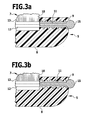
- eine Schnittansicht längs Linie 3-3 in Figur 2 vor dem Aufquellen einer quellfähigen Ummantelung eines Verankerungsabschnittes;
- Figur 3b:
- eine Ansicht ähnlich Figur 3a nach dem Aufquellen der quellfähigen Ummantelung des Verankerungsabschnittes;
- Figur 4:
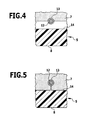
- eine Schnittansicht längs Linie 4-4 in Figur 2 vor dem Aufquellen des quellfähigen Materials;
- Figur 5:
- eine Ansicht ähnlich Figur 4 nach dem Aufquellen des quellfähigen Materials;
- Figur 6:
- eine Ansicht ähnlich Figur 2 bei einem Ausführungsbeispiel mit U-förmigen Verankerungsabschnitten;
- Figur 7:
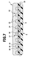
- eine Schnittansicht längs Linie 7-7 in Figur 6;
- Figur 8:
- eine Ansicht ähnlich Figur 2 mit einem netzförmigen Bauteil aus Verankerungsabschnitten und
- Figur 9:
- eine Schnittansicht längs Linie 9-9.
- In Figur 1 ist ein Zwischenwirbelimplantat 1 im Zwischenwirbelraum 2 zwischen zwei benachbarten Wirbelkörpern 3, 4 angeordnet. Es umfaßt eine untere Endplatte 5 und eine obere Endplatte 6 und einen zwischen diesen beiden Endplatten 5 und 6 angeordneten Kern 7. Die beiden Endplatten 5, 6 sind spiegelbildlich zueinander ausgebildet, nachfolgend wird daher nur die untere Endplatte 5 näher beschrieben.
- Sie umfaßt an ihrer Unterseite eine ebene Anlagefläche 8 und an ihrer Oberseite einen nach oben überstehenden, rahmenförmigen Rand 9, der in sich geschlossen ist und einen Innenraum 10 umschließt, der nach unten durch die Endplatte 5 verschlossen ist und nach oben hin offen ist.
- Die Endplatte 5 mit dem nach oben überstehenden Rand 9 besteht aus einem biegefesten und formstabilen, biokompatiblen Material, beispielsweise aus Titan oder einer Titanlegierung oder aber auch aus einem thermoplastischen Kunststoff, beispielsweise aus Polyetheretherketon. Im dargestellten Ausführungsbeispiel ist die Endplatte 5 im wesentlichen rechteckförmig ausgebildet mit abgerundeten Ecken und in ihrer Größe der Querschnittsfläche der Wirbelkörper 3, 4 angepaßt, so daß im wesentlichen der gesamte Zwischenwirbelraum von den Endplatten überdeckt wird.
- Bei dem in den Figuren 1 bis 3 dargestellten Ausführungsbeispiel sind in dem nach oben überstehenden Rand 9 eine größere Anzahl von quer zur Längsrichtung des Randes 9 verlaufenden Bohrungen 11 angeordnet, die in dem dargestellten Ausführungsbeispiel als durchgehende Innengewindebohrungen ausgeführt sind. In jeweils gegenüberliegende derartige Bohrungen 11 der Endplatte tauchen die Enden von faden- oder drahtförmigen Verankerungsabschnitten 12 ein, die sich auf diese Weise quer durch den gesamten Innenraum 10 erstrecken. Die Verankerungsabschnitte 12 von jeweils gegenüberliegenden Teilen des Randes 9 verlaufen parallel zueinander, und die Verankerungsabschnitte 12 der senkrecht zueinander verlaufenden Abschnitte des Randes 9 verlaufen dementsprechend senkrecht zueinander, das heißt sie überkreuzen sich und bilden somit eine netzartige Verankerungsfläche 13 aus. Diese erstreckt sich parallel zur Endplatte 5 im Abstand von deren Oberseite 14 und im Innenraum 10. Dabei wird der gesamte Innenraum gleichmäßig von den Verankerungsabschnitten 12 überdeckt, wie dies aus der Darstellung der Figur 2 zu entnehmen ist.
- Die Verankerungsabschnitte 12 sind mit ihren in die Bohrungen 11 eintauchenden Enden fest mit dem Rand 9 verbunden. Wie aus den Figuren 3a und 3b zu entnehmen ist, können die Verankerungsabschnitte 12 eine Beschichtung aus quellfähigem Material aufweisen, welches unter Wasseraufnahme sein Volumen vergrößert. Es kann sich dabei nur um die Ummantelung handeln, es kann aber auch vorgesehen sein, daß der Verankerungsabschnitt vollständig aus einem solchen Material besteht. Die Enden der in dieser Weise ausgebildeten Verankerungsabschnitte 12 sind im Bereich des Randes 9 in einer Innengewindebohrung angeordnet. Vor dem Aufquellen der quellfähigen Ummantelung tritt das quellfähige Material aufgrund seines geringen Volumens nicht in die Gewindegänge der Innengewindebohrung ein (Figur 3a), das heißt der Außendurchmesser der Verankerungsabschnitte entspricht dem kleinsten Innendurchmesser der Innengewindebohrung, so daß die Verankerungsabschnitte in die Innengewindebohrung eingeschoben werden können.
- Nach Flüssigkeitsaufnahme vergrößert sich das Volumen des quellfähigen Mantelmaterials oder des quellfähigen Materials der Verankerungsabschnitte derart, daß dieses Material in die Gewindegänge eintritt und diese mehr oder weniger vollständig ausfüllt, wie dies in Figur 3b dargestellt ist. Dadurch ergibt sich eine formschlüssige Verankerung der Verankerungsabschnitte im Rand 9.
- Die Festlegung der Verankerungsabschnitte 12 im Rand 9 kann aber auch ausschließlich oder zusätzlich durch Verdickungen 15 erfolgen, die an der Außenseite des Randes 9 anliegen und die Verankerungsabschnitte 12 zwischen den gegenüberliegenden Teilen des Rahmens 9 aufspannen.
- Die Verankerungsabschnitte 12 bestehen aus einem Material in Form eines Fadens, insbesondere eines biegeschlaffen Fadens oder in Form eines Drahtes oder eines sehr dünnen, länglichen Stabes, so daß zwischen der Oberseite 14 der Endplatte 5 und der Unterseite der Verankerungsabschnitte 12 ein Abstand verbleibt (Figur 4).
- Die Verankerungsabschnitte können vorzugsweise aus Metall bestehen, insbesondere aus Titan oder einer Titanlegierung, es sind aber auch andere Materialien verwendbar, beispielsweise hydrophobe Polymere wie verstrecktes Polyethylen, bevorzugt hochmolekulares Polyethylen, insbesondere ultrahochmolekulares Polyethylen (UHMWPE) oder nicht vollständig gequollenes Hydrogel, oder die Verankerungsabschnitte können aus einem Hydrogel oder einem Xerogel bestehen, also einem reinen, wasserfreien Polymer. Die Verankerungsabschnitte 12 können als Multifilament oder Monofilament ausgebildet sein, und es ist möglich, daß die Verankerungsabschnitte 12 zusätzlich beschichtet sind, beispielsweise mit einem quellfähigen Xerogel, welches bei Kontakt mit der vorhandenen Körperflüssigkeit ein Hydrogel ausbildet.
- Auf die von den Verankerungsabschnitten 12 ausgebildete Verankerungsfläche 13 ist der plattenförmige, in seinem Querschnitt dem Querschnitt des Innenraumes 10 angepaßte Kern aufgelegt, so daß dessen Unterseite auf den Verankerungsabschnitten 12 aufliegt. An der Oberseite des Zwischenwirbelimplantates 1 kann die gleich aufgebaute obere Endplatte 6 aufgelegt werden, die sich dann mit ihren Verankerungsabschnitten 12 an der Oberseite des Kerns 7 abstützt.
- Der Kern besteht aus einem quellfähigen Hydrogel, also einem Material, das unter Flüssigkeitsaufnahme sein Volumen vergrößern kann.
- Als Hydrogele kommen prinzipiell alle nicht degradierbaren hydrophilen Polymere in Frage. Beispiele sind Polyacrylsäure und deren Derivate wie Polymethacrylsäure, Polyacrylsäureamid, Polyacrylonitril, Polyacrylsäureester, Polyhydroxyethylmethacrylate, außerdem Polyvinylpyrrolidon (PVP), Polyurethane, hochmolekularer Polyvinylalkohol.
- Denkbar sind auch Polymerblends (Copolymere, welche über kovalente Bindungen miteinander verbunden sind) aus den oben genannten Polymeren oder Interpenetrating Networks (IPN) aus den oben genannten Polymeren. IPN bestehen aus mindestens zwei unterschiedlichen Polymeren, deren Polymerketten ineinander verhakt sind und über physikalische Wechselwirkungen (van der Waals-, elektrostatische, H-Brückenbindungen und / oder ionische Kräfte) miteinander verbunden sind.
- Weitere Polymermischungen, welche eingesetzt werden können, sind Copolymer sowie IPN aus Polyacrylaten (Polyacrylsäure und deren Derivate wie Polymethacrylsäure, Polyacrylsäureamid, Polyacrylsäurenitril, Polyacrylsäureester) mit Polycaprolacton.
- Das quellfähige Material des Kernes 7 vergrößert bei Flüssigkeitsaufnahme, das heißt nach der Implantation in den Zwischenwirbelraum 2, sein Volumen, und dabei umschließt das Material des Kernes 7 die Verankerungsabschnitte 12 der Verankerungsfläche 13 allseits, das heißt der gesamte Innenraum 10 der beiden Endplatten 5, 6 wird vollständig ausgefüllt, wie dies in Figur 5 dargestellt ist. Dadurch erfolgt eine Einbettung der Verankerungsabschnitte 12 in das Material des Kernes 7 und damit eine verzahnende Verbindung des Kernes mit den benachbarten Endplatten.
- Diese Verbindung kann noch dadurch verbessert werden, daß zwischen dem Material der Verankerungsabschnitte und dem Material des Kernes nicht nur ein Formschluß ausgebildet wird, sondern daß zusätzlich flexible elektrostatische, ionische oder van-der-Waals-Wechselwirkungen zur Verankerung des Kernes mit den Verankerungsabschnitten genutzt werden. Dabei lassen sich die Eigenschaften des Materials des Kernes 7, insbesondere die Quellfähigkeit, durch unterschiedliche Parameter des quellfähigen Materials in gewissen Grenzen variieren, beispielsweise durch die Verwendung eines unterschiedlichen Molekulargewichts, durch einen unterschiedlichen Vernetzungsgrad oder durch ein unterschiedliches Herstellungsverfahren.
- Insbesondere ergibt sich eine besonders gute Vernetzung bei Verankerungsabschnitten 12, die ihrerseits mit einem Polymer beschichtet sind, dabei kann es sich um dasselbe polymere Material handeln, wie beim Material des Kernes, es können aber auch unterschiedliche polymere Materialien eingesetzt werden, die miteinander eine innige Vernetzung eingehen.
- Bei dem Ausführungsbeispiel der Figuren 1 bis 5 liegen die Verankerungsabschnitte 12 in Form einer netzartigen Verankerungsfläche 13 vor.
- Es sind auch andere geometrische Anordnungen der Verankerungsabschnitte 12 auf den Endplatten 5, 6 möglich, wichtig ist lediglich, daß dem quellfähigen Material die Möglichkeit gegeben wird, die Verankerungsabschnitte allseitig zu umschließen.
- Bei dem Ausführungsbeispiel der Figuren 6 und 7 wird ein in die Endplatte 5 eingebettetes, drahtförmiges Bauelement durch nebeneinanderliegende Bohrungen 16 in der Oberseite 14 der Endplatte 5 so schlaufenförmig nach oben und wieder nach unten geführt, daß oberhalb der Oberseite 14 der Endplatte 5 im Querschnitt U-förmige Brücken oder Schlaufen 17 entstehen mit aus den Bohrungen 16 senkrecht nach oben austretenden parallelen Schenkeln 18, 19 und diese verbindenden, parallel zur Oberseite 14 und im Abstand von dieser verlaufenden Stegen 20. Eine größere Anzahl derartiger Reihen von Schlaufen 17 sind an der Oberseite 14 der Endplatte 5 nebeneinander angeordnet und überdecken dadurch die gesamte Oberseite 14. Die parallel zur Oberseite 14 verlaufenden Stege 20 bilden dabei eine Verankerungsfläche 13 aus, auf die der Kern 7 in ähnlicher Weise wie im Ausführungsbeispiel der Figuren 1 bis 5 aufgelegt wird. Beim Quellen umschließt das Material des Kernes dann die Stege 20 allseits und auch die aus der Oberseite 14 vorstehenden Schenkel 18, 19, so daß eine feste und sichere Verbindung zwischen dem Kern 7 und der Endplatte 5 gewährleistet ist.
- Die schlaufenförmigen Bauelemente können als Drahtelemente ausgebildet sein, also aus einem metallischen Werkstoff bestehen, insbesondere aus Titan oder einer Titanlegierung, es kann sich dabei aber auch um Polymerfäden handeln, die in diesem Falle vorzugsweise biegesteif ausgebildet sind, beispielsweise um Polyethylenfäden.
- Eine weitere mögliche Ausgestaltung ist in dem Ausführungsbeispiel der Figuren 8 und 9 dargestellt. Dort sind parallel zueinander verlaufende und sich kreuzende Verankerungsabschnitte 12 zu einer Verankerungsfläche 13 kombiniert, die als selbständig handhabbares Bauteil ausgebildet ist. Zu diesem Zweck können die Verankerungsabschnitte beispielsweise verwebt sein oder an den Kreuzungspunkten in geeigneter Weise miteinander verbunden sein. Im Randbereich wird dieses selbsttätig handhabbare, netzartige Bauteil 21 mit nach unten abgebogenen Rändern ausgebildet, das heißt die Enden der Verankerungsabschnitte 12 werden nach unten gebogen, so daß sie von außen an den Seitenflächen 20 der Endplatte 5 zur Anlage kommen, wenn das Bauteil 21 die Endplatte 5 überdeckend auf diese aufgelegt wird (Figur 8). Die Enden 23 der Verankerungsabschnitte 12 werden dann durch eine umlaufende Bandage 24 fest gegen die Seitenflächen 22 gedrückt, so daß dadurch das Bauteil 21 an der Endplatte 5 dauerhaft festgelegt wird. Die Fixierung wird dadurch unterstützt, daß in der Seitenfläche 22 eine umlaufende Nut 25 eingearbeitet ist, die sich längs der Seitenflächen 22 um die gesamte Endplatte 5 herum erstreckt und in die die Enden 23 durch die Bandage 24 hineingedrückt werden (Figur 9).
- Auf das Bauteil 21 ist in ähnlicher Weise wie bei den voranstehend beschriebenen Ausführungsbeispielen der Kern 7 aufgelegt, der dann beim Quellen die Verankerungsabschnitte 12 allseits umgibt und zu einer festen Verbindung mit der Endplatte 5 kommt.
- Grundsätzlich wäre es auch möglich, den Kern 7 bereits vor der Montage des Bauteils 21 an der Endplatte 5 mit dem Bauteil 21 zu verbinden, also das Bauteil 21 in den Kern 7 schon bei der Herstellung einzubetten. Ein Kern mit in dieser Weise eingebettetem Bauteil 21 kann dann auf eine Endplatte 5 aufgesetzt und durch die Bandage 24 an der Endplatte 5 festgelegt werden. Damit erhält man bereits eine Verbindung vor dem Quellen des quellfähigen Materials im Körper.
Claims (25)
- Zwischenwirbelimplantat (1) mit mindestens einem eine Wirbelkörper-Anlagefläche (8) aufweisenden Anlageelement und mit einem quellfähigen Kern (7), der auf der der Wirbelkörper-Anlagefläche (8) abgewandten Seite mit dem Anlageelement verbunden ist, wobei das Anlageelement einen Träger (5) umfaßt, auf dessen einer Seite die Wirbelkörper-Anlagefläche (8) angeordnet ist und der auf seiner anderen Seite Vorsprünge trägt, die von dem Material des Kernes (7) umschlossen werden, dadurch gekennzeichnet, daß die Vorsprünge längliche, faden-oder stabförmige Verankerungsabschnitte (12) aufweisen, die im Abstand vom Träger (5) verlaufen und allseits frei zugänglich sind.
- Implantat nach Anspruch 1, dadurch gekennzeichnet, daß die Verankerungsabschnitte (12) im wesentlichen parallel zur Wirbelkörper-Anlagefläche (8) und im Abstand von der der Wirbelkörper-Anlagefläche (8) abgewandten Seite (14) des Trägers (5) verlaufen.
- Implantat nach Anspruch 1 oder 2, dadurch gekennzeichnet, daß im wesentlichen die gesamte Fläche des Trägers (5) Verankerungsabschnitte (12) aufweist.
- Implantat nach einem der Ansprüche 1 bis 3, dadurch gekennzeichnet, daß mehrere Verankerungsabschnitte (12) parallel zueinander verlaufen.
- Implantat nach einem der Ansprüche 1 bis 3, dadurch gekennzeichnet, daß sich verschiedene Verankerungsabschnitte (12) überkreuzen.
- Implantat nach Anspruch 5, dadurch gekennzeichnet, daß sich überkreuzende Verankerungsabschnitte (12) eine netzförmige Struktur (13; 21) ausbilden.
- Implantat nach einem der voranstehenden Ansprüche, dadurch gekennzeichnet, daß der Träger (5) rahmenförmige Seitenteile (9) aufweist, an denen die Verankerungsabschnitte (12) gehalten sind.
- Implantat nach Anspruch 7, dadurch gekennzeichnet, daß die Verankerungsteile (12) in Bohrungen (11) der rahmenförmigen Seitenteile (9) eintauchen und in diesen festgelegt sind.
- Implantat nach Anspruch 8, dadurch gekennzeichnet, daß die Verankerungsteile (12) in die Bohrungen (11) eingeschraubt sind.
- Implantat nach Anspruch 8, dadurch gekennzeichnet, daß die Verankerungsteile (12) über Verdickungen (15) oder Knoten an der Außenseite der Seitenteile (9) in den Bohrungen (11) festgelegt sind.
- Implantat nach Anspruch 8, dadurch gekennzeichnet, daß die Verankerungsteile (12) aus quellfähigem Material bestehen und beim Quellen Vorsprünge und Rücksprünge in den Bohrungen (11) umschließen.
- Implantat nach einem der Ansprüche 1 bis 5, dadurch gekennzeichnet, daß die Verankerungsabschnitte (12) U-förmig ausgebildet sind mit zwei quer zu dem Träger (5) verlaufenden und die Verankerungsabschnitte (12) am Träger (5) festlegenden Schenkeln (18, 19) und einem diese verbindenden Steg (20).
- Implantat nach Anspruch 12, dadurch gekennzeichnet, daß die Schenkel (18, 19) und der Steg (20) im wesentlichen geradlinig verlaufen.
- Implantat nach Anspruch 12 oder 13, dadurch gekennzeichnet, daß die Schenkeln (18, 19) in Bohrungen (16) im Träger (5) eintauchen und in diesen festgelegt sind.
- Implantat nach einem der Ansprüche 12 bis 14, dadurch gekennzeichnet, daß mehrere benachbarte Verankerungsabschnitte (12) aus einem einzigen faden- oder stabförmigen Bauteil gebildet werden.
- Implantat nach einem der Ansprüche 5 oder 6, dadurch gekennzeichnet, daß sich überkreuzende Verankerungsteile (12) ein flächiges Bauelement (21) ausbilden, das an seinen Rändern mit dem Träger (5) verbunden ist.
- Implantat nach Anspruch 16, dadurch gekennzeichnet, daß der Träger (5) an seinen Seitenflächen (22) eine umlaufende Bandage (24) trägt, die die Ränder des flächigen Bauteils (21) gegen sie Seitenflächen (22) spannt.
- Implantat nach Anspruch 17, dadurch gekennzeichnet, daß die Seitenflächen (22) im Bereich der Bandage (24) eine umlaufende Nut (25) zur Aufnahme der Ränder des flächigen Bauteils (21) aufweisen.
- Implantat nach einem der voranstehenden Ansprüche, dadurch gekennzeichnet, daß die Verankerungsabschnitte (12) biegeschlaff ausgebildet sind.
- Implantat nach einem der voranstehenden Ansprüche, dadurch gekennzeichnet, daß die Verankerungsabschnitte (12) aus Metall bestehen.
- Implantat nach Anspruch 20, dadurch gekennzeichnet, daß die Verankerungsabschnitte (12) aus Titan oder einer Titanlegierung bestehen.
- Implantat nach Anspruch 20 oder 21, dadurch gekennzeichnet, daß die Verankerungsabschnitte (12) mit einem quellfähigen Material beschichtet sind.
- Implantat nach einem der Ansprüche 1 bis 19, dadurch gekennzeichnet, daß die Verankerungsabschnitte (12) aus einem hydrophoben Polymer bestehen.
- Implantat nach Anspruch 23, dadurch gekennzeichnet, daß die Verankerungsabschnitte (12) aus Polyethylen bestehen.
- Implantat nach einem der Ansprüche 1 bis 19, dadurch gekennzeichnet, daß die Verankerungsabschnitte (12) aus einem Hydrogel oder einem Xerogel bestehen.
Applications Claiming Priority (1)
| Application Number | Priority Date | Filing Date | Title |
|---|---|---|---|
| DE102006016986A DE102006016986A1 (de) | 2006-04-06 | 2006-04-06 | Zwischenwirbelimplantat |
Publications (2)
| Publication Number | Publication Date |
|---|---|
| EP1842510A1 true EP1842510A1 (de) | 2007-10-10 |
| EP1842510B1 EP1842510B1 (de) | 2008-09-03 |
Family
ID=38222726
Family Applications (1)
| Application Number | Title | Priority Date | Filing Date |
|---|---|---|---|
| EP07004640A Active EP1842510B1 (de) | 2006-04-06 | 2007-03-07 | Zwischenwirbelimplantat |
Country Status (5)
| Country | Link |
|---|---|
| US (1) | US20070239277A1 (de) |
| EP (1) | EP1842510B1 (de) |
| AT (1) | ATE406856T1 (de) |
| DE (2) | DE102006016986A1 (de) |
| ES (1) | ES2310919T3 (de) |
Families Citing this family (6)
| Publication number | Priority date | Publication date | Assignee | Title |
|---|---|---|---|---|
| DE102008005998B4 (de) * | 2008-01-25 | 2010-01-14 | Aesculap Ag | Zwischenwirbelimplantat |
| US9050194B2 (en) | 2009-05-06 | 2015-06-09 | Stryker Spine | Expandable spinal implant apparatus and method of use |
| US8353964B2 (en) * | 2010-11-04 | 2013-01-15 | Carpenter Clyde T | Anatomic total disc replacement |
| EP2903567B1 (de) * | 2012-10-02 | 2017-08-09 | McCullen, Seth | Implantierbare vorrichtungen für muskuloskelettäre reparatur und regeneration |
| WO2016054463A1 (en) | 2014-10-02 | 2016-04-07 | Mccullen Seth | Anatomically designed meniscus implantable devices |
| WO2018204440A2 (en) | 2017-05-02 | 2018-11-08 | Mccullen Seth | Composite joint implant |
Citations (3)
| Publication number | Priority date | Publication date | Assignee | Title |
|---|---|---|---|---|
| US5314478A (en) * | 1991-03-29 | 1994-05-24 | Kyocera Corporation | Artificial bone connection prosthesis |
| EP0610837A1 (de) * | 1993-02-09 | 1994-08-17 | Acromed Corporation | Bandscheibe |
| US20040068320A1 (en) * | 2002-10-04 | 2004-04-08 | Robie Bruce H. | Prosthetic disc and vertebral body replacement device having pyrolytic carbon bearing members |
Family Cites Families (18)
| Publication number | Priority date | Publication date | Assignee | Title |
|---|---|---|---|---|
| JPH01136655A (ja) * | 1987-11-24 | 1989-05-29 | Asahi Optical Co Ltd | 人工椎間板 |
| CA1318469C (en) * | 1989-02-15 | 1993-06-01 | Acromed Corporation | Artificial disc |
| FR2709949B1 (fr) * | 1993-09-14 | 1995-10-13 | Commissariat Energie Atomique | Prothèse de disque intervertébral. |
| US5824094A (en) * | 1997-10-17 | 1998-10-20 | Acromed Corporation | Spinal disc |
| US20010016773A1 (en) * | 1998-10-15 | 2001-08-23 | Hassan Serhan | Spinal disc |
| US6139579A (en) * | 1997-10-31 | 2000-10-31 | Depuy Motech Acromed, Inc. | Spinal disc |
| US6162252A (en) * | 1997-12-12 | 2000-12-19 | Depuy Acromed, Inc. | Artificial spinal disc |
| US6602291B1 (en) * | 1999-04-05 | 2003-08-05 | Raymedica, Inc. | Prosthetic spinal disc nucleus having a shape change characteristic |
| US7066960B1 (en) * | 2002-06-28 | 2006-06-27 | Dickman Curtis A | Intervertebral disk replacement |
| JP4240399B2 (ja) * | 2003-04-14 | 2009-03-18 | ジンテーズ ゲゼルシャフト ミト ベシュレンクテル ハフツング | 椎間インプラント |
| US20050216087A1 (en) * | 2004-01-05 | 2005-09-29 | St. Francis Medical Technologies, Inc. | Disk repair structures for positioning disk repair material |
| US8012210B2 (en) * | 2004-01-16 | 2011-09-06 | Warsaw Orthopedic, Inc. | Implant frames for use with settable materials and related methods of use |
| US20060058881A1 (en) * | 2004-09-16 | 2006-03-16 | Trieu Hai H | Intervertebral disc nucleus implants and methods |
| US20060173542A1 (en) * | 2004-12-28 | 2006-08-03 | Takiron Co., Ltd. | Biomaterial for artificial cartilage |
| US8864831B2 (en) * | 2005-01-19 | 2014-10-21 | K2M, Inc. | Fixation of elastomer to rigid structures |
| US20070150059A1 (en) * | 2005-12-22 | 2007-06-28 | Depuy Spine, Inc. | Methods and devices for intervertebral augmentation using injectable formulations and enclosures |
| WO2007130648A2 (en) * | 2006-05-05 | 2007-11-15 | Ceramatec, Inc. | Fully or partially bioresorbable orthopedic implant |
| US20070270969A1 (en) * | 2006-05-17 | 2007-11-22 | Schmid Steven R | Welded-woven materials |
-
2006
- 2006-04-06 DE DE102006016986A patent/DE102006016986A1/de not_active Withdrawn
-
2007
- 2007-03-07 ES ES07004640T patent/ES2310919T3/es active Active
- 2007-03-07 EP EP07004640A patent/EP1842510B1/de active Active
- 2007-03-07 DE DE502007000095T patent/DE502007000095D1/de active Active
- 2007-03-07 AT AT07004640T patent/ATE406856T1/de active
- 2007-04-03 US US11/732,697 patent/US20070239277A1/en not_active Abandoned
Patent Citations (3)
| Publication number | Priority date | Publication date | Assignee | Title |
|---|---|---|---|---|
| US5314478A (en) * | 1991-03-29 | 1994-05-24 | Kyocera Corporation | Artificial bone connection prosthesis |
| EP0610837A1 (de) * | 1993-02-09 | 1994-08-17 | Acromed Corporation | Bandscheibe |
| US20040068320A1 (en) * | 2002-10-04 | 2004-04-08 | Robie Bruce H. | Prosthetic disc and vertebral body replacement device having pyrolytic carbon bearing members |
Also Published As
| Publication number | Publication date |
|---|---|
| EP1842510B1 (de) | 2008-09-03 |
| DE102006016986A1 (de) | 2007-10-18 |
| ATE406856T1 (de) | 2008-09-15 |
| US20070239277A1 (en) | 2007-10-11 |
| DE502007000095D1 (de) | 2008-10-16 |
| ES2310919T3 (es) | 2009-01-16 |
Similar Documents
| Publication | Publication Date | Title |
|---|---|---|
| EP1842510B1 (de) | Zwischenwirbelimplantat | |
| DE10004712C1 (de) | Knochenplatte | |
| DE69223264T2 (de) | Implantierbare leitung | |
| DE69839098T2 (de) | Spannungsregulierender fusionskäfig für wirbelsäulenfusionschirurgie | |
| DE102008005998A1 (de) | Zwischenwirbelimplantat | |
| US20030120257A1 (en) | Method for introducing an internal helical formation into a flexible tubular material | |
| EP0622058A2 (de) | Implantierbares Verankerungsorgan zur Aufnahme von Prothesen, künstlichen Gelenkteilen u.dgl. | |
| EP2502604A1 (de) | Gelenkpfannenimplantat | |
| AT515117B1 (de) | Zahnimplantatsystem | |
| DE102010036489A1 (de) | Behälterunterteil und Behälteroberteil eines Sterilbehälters und Sterilbehälter | |
| EP2946750B1 (de) | Stent-graft und einführvorrichtung | |
| DE19816828A1 (de) | Zwischenwirbelfusionsimplantat | |
| DE102007051782B4 (de) | Implantat zum Ersetzen einer Facettengelenkfläche | |
| EP1624831A1 (de) | Vorrichtung zur implantation in eine menschliche oder tierische wirbelsäule | |
| EP2203133B1 (de) | Facettengelenkimplantat | |
| EP0663193A1 (de) | Künstliche Hüftgelenkpfanne | |
| DE20315613U1 (de) | Zwischenwirbelimplantat | |
| DE19520158C2 (de) | Chirurgischer Clip | |
| DE102010004133A1 (de) | Spreizbares Zwischenwirbelimplantat zum Einsetzen zwischen benachbarten Wirbelkörpern | |
| WO2010006786A1 (de) | Implantat mit einer geflochtenen gitterstruktur und verfahren zum herstellen eines derartigen implantats | |
| EP2355754B1 (de) | Implantat | |
| DE202006005896U1 (de) | Zwischenwirbelimplantat | |
| DE102006029605A1 (de) | Brustimplantat | |
| DE202008013320U1 (de) | Implantat zur Fixierung benachbarter Knochenplatten | |
| WO2001056506A1 (de) | Implantat zur temporären fixation von gewebe |
Legal Events
| Date | Code | Title | Description |
|---|---|---|---|
| PUAI | Public reference made under article 153(3) epc to a published international application that has entered the european phase |
Free format text: ORIGINAL CODE: 0009012 |
|
| AK | Designated contracting states |
Kind code of ref document: A1 Designated state(s): AT BE BG CH CY CZ DE DK EE ES FI FR GB GR HU IE IS IT LI LT LU LV MC MT NL PL PT RO SE SI SK TR |
|
| AX | Request for extension of the european patent |
Extension state: AL BA HR MK YU |
|
| 17P | Request for examination filed |
Effective date: 20070908 |
|
| GRAP | Despatch of communication of intention to grant a patent |
Free format text: ORIGINAL CODE: EPIDOSNIGR1 |
|
| AKX | Designation fees paid |
Designated state(s): AT BE BG CH CY CZ DE DK EE ES FI FR GB GR HU IE IS IT LI LT LU LV MC MT NL PL PT RO SE SI SK TR |
|
| GRAS | Grant fee paid |
Free format text: ORIGINAL CODE: EPIDOSNIGR3 |
|
| RAP1 | Party data changed (applicant data changed or rights of an application transferred) |
Owner name: AESCULAP AG |
|
| GRAA | (expected) grant |
Free format text: ORIGINAL CODE: 0009210 |
|
| AK | Designated contracting states |
Kind code of ref document: B1 Designated state(s): AT BE BG CH CY CZ DE DK EE ES FI FR GB GR HU IE IS IT LI LT LU LV MC MT NL PL PT RO SE SI SK TR |
|
| REG | Reference to a national code |
Ref country code: GB Ref legal event code: FG4D Free format text: NOT ENGLISH |
|
| REG | Reference to a national code |
Ref country code: CH Ref legal event code: NV Representative=s name: ISLER & PEDRAZZINI AG Ref country code: CH Ref legal event code: EP |
|
| REG | Reference to a national code |
Ref country code: IE Ref legal event code: FG4D Free format text: LANGUAGE OF EP DOCUMENT: GERMAN |
|
| REF | Corresponds to: |
Ref document number: 502007000095 Country of ref document: DE Date of ref document: 20081016 Kind code of ref document: P |
|
| REG | Reference to a national code |
Ref country code: ES Ref legal event code: FG2A Ref document number: 2310919 Country of ref document: ES Kind code of ref document: T3 |
|
| PG25 | Lapsed in a contracting state [announced via postgrant information from national office to epo] |
Ref country code: NL Free format text: LAPSE BECAUSE OF FAILURE TO SUBMIT A TRANSLATION OF THE DESCRIPTION OR TO PAY THE FEE WITHIN THE PRESCRIBED TIME-LIMIT Effective date: 20080903 Ref country code: LT Free format text: LAPSE BECAUSE OF FAILURE TO SUBMIT A TRANSLATION OF THE DESCRIPTION OR TO PAY THE FEE WITHIN THE PRESCRIBED TIME-LIMIT Effective date: 20080903 |
|
| PG25 | Lapsed in a contracting state [announced via postgrant information from national office to epo] |
Ref country code: LV Free format text: LAPSE BECAUSE OF FAILURE TO SUBMIT A TRANSLATION OF THE DESCRIPTION OR TO PAY THE FEE WITHIN THE PRESCRIBED TIME-LIMIT Effective date: 20080903 Ref country code: SI Free format text: LAPSE BECAUSE OF FAILURE TO SUBMIT A TRANSLATION OF THE DESCRIPTION OR TO PAY THE FEE WITHIN THE PRESCRIBED TIME-LIMIT Effective date: 20080903 Ref country code: FI Free format text: LAPSE BECAUSE OF FAILURE TO SUBMIT A TRANSLATION OF THE DESCRIPTION OR TO PAY THE FEE WITHIN THE PRESCRIBED TIME-LIMIT Effective date: 20080903 |
|
| NLV1 | Nl: lapsed or annulled due to failure to fulfill the requirements of art. 29p and 29m of the patents act | ||
| REG | Reference to a national code |
Ref country code: IE Ref legal event code: FD4D |
|
| PG25 | Lapsed in a contracting state [announced via postgrant information from national office to epo] |
Ref country code: IE Free format text: LAPSE BECAUSE OF FAILURE TO SUBMIT A TRANSLATION OF THE DESCRIPTION OR TO PAY THE FEE WITHIN THE PRESCRIBED TIME-LIMIT Effective date: 20080903 Ref country code: BG Free format text: LAPSE BECAUSE OF FAILURE TO SUBMIT A TRANSLATION OF THE DESCRIPTION OR TO PAY THE FEE WITHIN THE PRESCRIBED TIME-LIMIT Effective date: 20081203 |
|
| PG25 | Lapsed in a contracting state [announced via postgrant information from national office to epo] |
Ref country code: IS Free format text: LAPSE BECAUSE OF FAILURE TO SUBMIT A TRANSLATION OF THE DESCRIPTION OR TO PAY THE FEE WITHIN THE PRESCRIBED TIME-LIMIT Effective date: 20090103 Ref country code: PT Free format text: LAPSE BECAUSE OF FAILURE TO SUBMIT A TRANSLATION OF THE DESCRIPTION OR TO PAY THE FEE WITHIN THE PRESCRIBED TIME-LIMIT Effective date: 20090203 Ref country code: CZ Free format text: LAPSE BECAUSE OF FAILURE TO SUBMIT A TRANSLATION OF THE DESCRIPTION OR TO PAY THE FEE WITHIN THE PRESCRIBED TIME-LIMIT Effective date: 20080903 Ref country code: SK Free format text: LAPSE BECAUSE OF FAILURE TO SUBMIT A TRANSLATION OF THE DESCRIPTION OR TO PAY THE FEE WITHIN THE PRESCRIBED TIME-LIMIT Effective date: 20080903 Ref country code: RO Free format text: LAPSE BECAUSE OF FAILURE TO SUBMIT A TRANSLATION OF THE DESCRIPTION OR TO PAY THE FEE WITHIN THE PRESCRIBED TIME-LIMIT Effective date: 20080903 |
|
| PLBE | No opposition filed within time limit |
Free format text: ORIGINAL CODE: 0009261 |
|
| STAA | Information on the status of an ep patent application or granted ep patent |
Free format text: STATUS: NO OPPOSITION FILED WITHIN TIME LIMIT |
|
| PG25 | Lapsed in a contracting state [announced via postgrant information from national office to epo] |
Ref country code: DK Free format text: LAPSE BECAUSE OF FAILURE TO SUBMIT A TRANSLATION OF THE DESCRIPTION OR TO PAY THE FEE WITHIN THE PRESCRIBED TIME-LIMIT Effective date: 20080903 Ref country code: EE Free format text: LAPSE BECAUSE OF FAILURE TO SUBMIT A TRANSLATION OF THE DESCRIPTION OR TO PAY THE FEE WITHIN THE PRESCRIBED TIME-LIMIT Effective date: 20080903 |
|
| 26N | No opposition filed |
Effective date: 20090604 |
|
| BERE | Be: lapsed |
Owner name: AESCULAP A.G. Effective date: 20090331 |
|
| PG25 | Lapsed in a contracting state [announced via postgrant information from national office to epo] |
Ref country code: MC Free format text: LAPSE BECAUSE OF NON-PAYMENT OF DUE FEES Effective date: 20090331 |
|
| PG25 | Lapsed in a contracting state [announced via postgrant information from national office to epo] |
Ref country code: SE Free format text: LAPSE BECAUSE OF FAILURE TO SUBMIT A TRANSLATION OF THE DESCRIPTION OR TO PAY THE FEE WITHIN THE PRESCRIBED TIME-LIMIT Effective date: 20081203 |
|
| PG25 | Lapsed in a contracting state [announced via postgrant information from national office to epo] |
Ref country code: BE Free format text: LAPSE BECAUSE OF NON-PAYMENT OF DUE FEES Effective date: 20090331 |
|
| PG25 | Lapsed in a contracting state [announced via postgrant information from national office to epo] |
Ref country code: PL Free format text: LAPSE BECAUSE OF FAILURE TO SUBMIT A TRANSLATION OF THE DESCRIPTION OR TO PAY THE FEE WITHIN THE PRESCRIBED TIME-LIMIT Effective date: 20080903 |
|
| PG25 | Lapsed in a contracting state [announced via postgrant information from national office to epo] |
Ref country code: GR Free format text: LAPSE BECAUSE OF FAILURE TO SUBMIT A TRANSLATION OF THE DESCRIPTION OR TO PAY THE FEE WITHIN THE PRESCRIBED TIME-LIMIT Effective date: 20081204 |
|
| PG25 | Lapsed in a contracting state [announced via postgrant information from national office to epo] |
Ref country code: IT Free format text: LAPSE BECAUSE OF NON-PAYMENT OF DUE FEES Effective date: 20100307 |
|
| PG25 | Lapsed in a contracting state [announced via postgrant information from national office to epo] |
Ref country code: LU Free format text: LAPSE BECAUSE OF NON-PAYMENT OF DUE FEES Effective date: 20090307 |
|
| PG25 | Lapsed in a contracting state [announced via postgrant information from national office to epo] |
Ref country code: HU Free format text: LAPSE BECAUSE OF FAILURE TO SUBMIT A TRANSLATION OF THE DESCRIPTION OR TO PAY THE FEE WITHIN THE PRESCRIBED TIME-LIMIT Effective date: 20090304 |
|
| PG25 | Lapsed in a contracting state [announced via postgrant information from national office to epo] |
Ref country code: TR Free format text: LAPSE BECAUSE OF FAILURE TO SUBMIT A TRANSLATION OF THE DESCRIPTION OR TO PAY THE FEE WITHIN THE PRESCRIBED TIME-LIMIT Effective date: 20080903 |
|
| PG25 | Lapsed in a contracting state [announced via postgrant information from national office to epo] |
Ref country code: CY Free format text: LAPSE BECAUSE OF FAILURE TO SUBMIT A TRANSLATION OF THE DESCRIPTION OR TO PAY THE FEE WITHIN THE PRESCRIBED TIME-LIMIT Effective date: 20080903 |
|
| PGFP | Annual fee paid to national office [announced via postgrant information from national office to epo] |
Ref country code: IT Payment date: 20140325 Year of fee payment: 8 Ref country code: AT Payment date: 20140320 Year of fee payment: 8 |
|
| REG | Reference to a national code |
Ref country code: DE Ref legal event code: R082 Ref document number: 502007000095 Country of ref document: DE Representative=s name: HOEGER, STELLRECHT & PARTNER PATENTANWAELTE MB, DE |
|
| REG | Reference to a national code |
Ref country code: AT Ref legal event code: MM01 Ref document number: 406856 Country of ref document: AT Kind code of ref document: T Effective date: 20150307 |
|
| PG25 | Lapsed in a contracting state [announced via postgrant information from national office to epo] |
Ref country code: IT Free format text: LAPSE BECAUSE OF NON-PAYMENT OF DUE FEES Effective date: 20150307 |
|
| PG25 | Lapsed in a contracting state [announced via postgrant information from national office to epo] |
Ref country code: AT Free format text: LAPSE BECAUSE OF NON-PAYMENT OF DUE FEES Effective date: 20150307 |
|
| REG | Reference to a national code |
Ref country code: FR Ref legal event code: PLFP Year of fee payment: 10 |
|
| PGFP | Annual fee paid to national office [announced via postgrant information from national office to epo] |
Ref country code: CH Payment date: 20160322 Year of fee payment: 10 Ref country code: ES Payment date: 20160322 Year of fee payment: 10 Ref country code: DE Payment date: 20160322 Year of fee payment: 10 |
|
| PGFP | Annual fee paid to national office [announced via postgrant information from national office to epo] |
Ref country code: GB Payment date: 20160322 Year of fee payment: 10 Ref country code: FR Payment date: 20160322 Year of fee payment: 10 |
|
| REG | Reference to a national code |
Ref country code: DE Ref legal event code: R119 Ref document number: 502007000095 Country of ref document: DE |
|
| REG | Reference to a national code |
Ref country code: CH Ref legal event code: PL |
|
| GBPC | Gb: european patent ceased through non-payment of renewal fee |
Effective date: 20170307 |
|
| REG | Reference to a national code |
Ref country code: FR Ref legal event code: ST Effective date: 20171130 |
|
| PG25 | Lapsed in a contracting state [announced via postgrant information from national office to epo] |
Ref country code: DE Free format text: LAPSE BECAUSE OF NON-PAYMENT OF DUE FEES Effective date: 20171003 Ref country code: FR Free format text: LAPSE BECAUSE OF NON-PAYMENT OF DUE FEES Effective date: 20170331 |
|
| PG25 | Lapsed in a contracting state [announced via postgrant information from national office to epo] |
Ref country code: LI Free format text: LAPSE BECAUSE OF NON-PAYMENT OF DUE FEES Effective date: 20170331 Ref country code: GB Free format text: LAPSE BECAUSE OF NON-PAYMENT OF DUE FEES Effective date: 20170307 Ref country code: CH Free format text: LAPSE BECAUSE OF NON-PAYMENT OF DUE FEES Effective date: 20170331 |
|
| REG | Reference to a national code |
Ref country code: ES Ref legal event code: FD2A Effective date: 20180703 |
|
| PG25 | Lapsed in a contracting state [announced via postgrant information from national office to epo] |
Ref country code: ES Free format text: LAPSE BECAUSE OF NON-PAYMENT OF DUE FEES Effective date: 20170308 |