EP1841631B1 - Fastening system for fastening a rear window wiper to a vehicle - Google Patents
Fastening system for fastening a rear window wiper to a vehicle Download PDFInfo
- Publication number
- EP1841631B1 EP1841631B1 EP05850236A EP05850236A EP1841631B1 EP 1841631 B1 EP1841631 B1 EP 1841631B1 EP 05850236 A EP05850236 A EP 05850236A EP 05850236 A EP05850236 A EP 05850236A EP 1841631 B1 EP1841631 B1 EP 1841631B1
- Authority
- EP
- European Patent Office
- Prior art keywords
- latching
- bearing body
- fastening system
- vehicle
- wiper
- Prior art date
- Legal status (The legal status is an assumption and is not a legal conclusion. Google has not performed a legal analysis and makes no representation as to the accuracy of the status listed.)
- Not-in-force
Links
Images


Classifications
-
- B—PERFORMING OPERATIONS; TRANSPORTING
- B60—VEHICLES IN GENERAL
- B60S—SERVICING, CLEANING, REPAIRING, SUPPORTING, LIFTING, OR MANOEUVRING OF VEHICLES, NOT OTHERWISE PROVIDED FOR
- B60S1/00—Cleaning of vehicles
- B60S1/02—Cleaning windscreens, windows or optical devices
- B60S1/04—Wipers or the like, e.g. scrapers
- B60S1/32—Wipers or the like, e.g. scrapers characterised by constructional features of wiper blade arms or blades
- B60S1/34—Wiper arms; Mountings therefor
- B60S1/3488—Means for mounting wiper arms onto the vehicle
- B60S1/349—Means for mounting the wiper bearing to the vehicle body
-
- B—PERFORMING OPERATIONS; TRANSPORTING
- B60—VEHICLES IN GENERAL
- B60S—SERVICING, CLEANING, REPAIRING, SUPPORTING, LIFTING, OR MANOEUVRING OF VEHICLES, NOT OTHERWISE PROVIDED FOR
- B60S1/00—Cleaning of vehicles
- B60S1/02—Cleaning windscreens, windows or optical devices
- B60S1/56—Cleaning windscreens, windows or optical devices specially adapted for cleaning other parts or devices than front windows or windscreens
- B60S1/58—Cleaning windscreens, windows or optical devices specially adapted for cleaning other parts or devices than front windows or windscreens for rear windows
- B60S1/583—Cleaning windscreens, windows or optical devices specially adapted for cleaning other parts or devices than front windows or windscreens for rear windows including wiping devices
-
- B—PERFORMING OPERATIONS; TRANSPORTING
- B60—VEHICLES IN GENERAL
- B60S—SERVICING, CLEANING, REPAIRING, SUPPORTING, LIFTING, OR MANOEUVRING OF VEHICLES, NOT OTHERWISE PROVIDED FOR
- B60S1/00—Cleaning of vehicles
- B60S1/02—Cleaning windscreens, windows or optical devices
- B60S1/04—Wipers or the like, e.g. scrapers
- B60S1/043—Attachment of the wiper assembly to the vehicle
- B60S1/0438—Attachement of separate wiper motor assembly to the vehicle
Definitions
- the invention relates to a fastening arrangement for a rear window wiper on a vehicle, in which the electric drive device is arranged in the interior of the vehicle body and the wiper shaft carrying the rear window wiper is guided to the outside.
- Rear wiper devices of the type described above generally have a wiper motor and a worm gear coupled to its output shaft, on the worm wheel eccentrically a pin is mounted, which acts on a coupling rod, the rotational movement of the worm wheel on a sprocket segment and a non-rotatably connected to the wiper shaft Gear or segment in a pendulum motion of the wiper shaft and arranged on this wiper arm.
- the wiper motor can also be a reversible motor, which is connected to a planetary gear, the output shaft is also the wiper shaft.
- the drive units (drive devices) are each arranged inside the vehicle, and the wiper shaft and a bearing for these are guided through a through hole to the outside.
- the arrangement may be made so that the respective drive device fixed to the body structure and the wiper shaft are guided through the lower edge of the rear window in the middle.
- the associated advantage is a large wiping field with a pendulum motion of the wiper arm in an angular range of 180 °, whereby the corner regions of the rear window can be detected with.
- the arrangement requires the introduction of a corresponding hole in the rear window.
- the wiper shaft is rotatably mounted in a sleeve-like spacer by means of a bushing (wiper shaft bearing), which extends with play through an opening in the rear window.
- a bushing wiper shaft bearing
- This clearance is sealed by two annular sealing members of an elastomeric material by means of a glass protector disposed between the outer circumference of the sleeve and the inner peripheries of the two circular sealing members.
- the latter also prevent the transmission of mechanical vibrations from the wiper shaft to the rear window (acoustic decoupling).
- the determination of the windshield wiper device is carried out in addition to a body baffle with the help of a bracket to which the wiper motor is attached.
- At one in the DE 694 06 244 T2 described mounting arrangement is between a wiper shaft receiving bearing and a through hole (opening) in the rear window the vehicle or in a part of the vehicle body, a remote mounting sleeve inserted to allow the attachment of the drive device with a clamping nut on a extending on the outside of the vehicle threaded portion of the bearing. Between the mounting sleeve and the edge of the through hole, a seal is arranged, on which the clamping nut rests with a washer.
- the drive unit is attached to a mounting plate which is arranged fixed to the vehicle.
- a generic mounting arrangement is from the WO-A-01/08945 known.
- the insert is advantageously connected by an adhesive bond with the body panel and the outside is designed such that it is flush with the rear window.
- the inside of the vehicle formed into a mounting bracket insert takes the bearing body with the wiper shaft and connected to this drive device via a latching connection so that the entire windshield wiper system is easily releasably attached to the insert. A screwing the same with the vehicle body is unnecessary so that the assembly process is shortened.
- the vehicle inner side end portion of the support bracket may be formed into a latching sleeve consisting of a plurality of axially parallel latching segments for the bearing body, which engages behind an annular bead formed in this latching state.
- the locking segments bearing body side be adapted to the annular bead and enclose them positively in VerrastungsSullivan, which contributes to the stability and reliability of the attachment, especially in conjunction with a clamp that can be arranged on the locking sleeve and presses the locking segments to the bearing body.
- the locking connection between the bearing body and the support bracket or insert can also be designed such that the bearing body has on its peripheral surface formed in the axial direction locking element with a molded on the drive device side of the molded mushroom-shaped locking head which engages in a trained on the support bracket guide groove in which in the direction of the vehicle outside on the locking element to inclined elastic locking webs are formed, which engage behind the locking head in the Verrastungsposition.
- the locking webs are to be bent out of the rear grip and thereby to press into trained pockets.
- a rubber-elastic element is arranged, which seals the bearing body relative to the support bracket and thus the windshield wiper device relative to the insert in the axial-radial direction.
- the rubber-elastic element takes over the acoustic decoupling of the drive device from the insert and thus of the vehicle body and of the Fahrzugemia. Further fastening and decoupling omitted.
- the rubber-elastic element may be formed as an axially extending sealing sleeve, which is produced in a space provided between the bearing body and the support bracket for this space by injecting the rubber-elastic material.
- the rubber-elastic element may be provided in the arrangement region of the sealing sleeve or in the region of the intermediate space with concentric grooves.
- Fig. 1 shows a arranged on the rear window 1 a tailgate 2 of a vehicle windshield wiper system with a pendulum driven wiper shaft 3, a non-rotatably mounted on this wiper arm 4 and at a free end fixed to the vehicle spray nozzle 5, which will not be discussed further below, and a Connecting device 6 for a wiper blade 7.
- the wiper shaft 3 and the vehicle inside arranged electrical drive device (30, Fig. 3 ) for these are mounted on an insert 8 made of plastic, which in a recess (9, Fig. 2 ) is formed in the adjacent to the rear window 1 body panel 10.
- This insert 8 allows the arrangement of the wiper shaft 3 in the boundary region between the body panel 10 and the rear window 1, so that the wiper arm 4 and wiper blade 7 formed wiper sweeps a wiping field 11 of substantially 180 °, which is indicated by dashed lines.
- the insert 8 has a vehicle interior side formed and inserted into the recess 9 mounting plate 13 with a support bracket 14 and a vehicle outside trained and integrally connected thereto cover plate 15, which overlaps the recess 9 surrounding body panel edge outside and in a is arranged by the outer body panel 16 formed recess 17, with its outer surface is flush and a uniform joint 18 is formed with this.
- cover plate 15 In the lateral transition regions between the plates 13 and 15, a thin wall projection 19 is formed in each case, which covers the given in the recess 9 between the body panel edge and the support bar 13 gap 20.
- an opening 22 is formed, the arrangement and implementation of the in a bearing body (21, Fig.
- the support bracket 14 has at its Vehicle inside end portion of a detent segments 23 formed detent sleeve 24 for connection to the bearing body (21).
- This insert 8 is connected by means of a bead of adhesive 25 with the recess 9 surrounding body panel edge cohesively.
- the rear window 1 is adapted to the shape of the cover plate 15 and is positively on derem upper edge 26 and on the adjoining edge 27 of the body outer panel 16 in the region of the recess 17 and is by means of an adhesive layer, not shown on the support plate 13 and by means of Adhesive bead 25 firmly connected to the body panel edge.
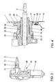
- Fig. 3 shows a drive device 30 formed by a wiper motor 28 and a gear 29 with the oscillating driven and guided in the bearing body 21 wiper shaft 3 for rotationally fixed arrangement of the wiper arm 4, wherein the drive device connected to the bearing body 21 drive device side, an annular bead 31 which is connected to the latching sleeve 24th the support bracket 14 is engageable, and has concentrically arranged grooves 32 on its circumference.
- the support bracket 14 encloses the bearing body 21, wherein the locking segments 23 engage behind the annular bead 31, so that the bearing body 21 carrying the drive device 30 is firmly, but releasably braced with the support bracket 14.
- the locking segments 23 are peripherally provided with a recess 33 for receiving a clamp 34, which stabilizes the latching connection and secures against rotation of the bearing body 21 in the bracket 14.
- annular gap 35 is formed in the region between the front region of the bearing body 21 and the annular bead 31, in which the bearing body 21 is provided with the concentrically arranged grooves 32 and in which a sealing and at the same acoustic decoupling element 36th is injected from a rubber-elastic material.
- a support bracket 37 which is formed inside the vehicle inside the insert 8, and a bearing body 38
- the latter have on its peripheral surface formed in the axial direction arrow-shaped locking element 39 with a mushroom-shaped locking head 40 and the support bracket 37 a guide 41 and a latching recess 42 for the locking element 39.
- two elastically bendable locking webs 43 are integrally formed, which are pressed apart during insertion of the locking element 39 and engage behind the locking head 40 in its locking position, which in Fig. 5b is shown.
- the two locking webs pressed apart and thereby released from the rear grip, so that the locking element 39 can be pulled by the guide groove 41 from the recess 42.
Landscapes
- Engineering & Computer Science (AREA)
- Mechanical Engineering (AREA)
- Power-Operated Mechanisms For Wings (AREA)
- Seal Device For Vehicle (AREA)
- Body Structure For Vehicles (AREA)
Abstract
Description
Die Erfindung betrifft eine Befestigungsanordnung für einen Heckscheibenwischer an einem Fahrzeug, bei der die elektrische Antriebsvorrichtung im Innern der Fahrzeugkarosserie angeordnet und die den Heckscheibenwischer tragende Wischerwelle nach außen geführt ist.The invention relates to a fastening arrangement for a rear window wiper on a vehicle, in which the electric drive device is arranged in the interior of the vehicle body and the wiper shaft carrying the rear window wiper is guided to the outside.
Heckscheibenwischervorrichtungen der vorstehend beschriebenen Art weisen in der Regel einen Wischermotor und ein mit dessen Abtriebswelle gekoppeltes Schneckengetriebe auf, an dessen Schneckenrad exzentrisch ein Zapfen gelagert ist, der an einer Koppelstange angreift, die die Rotationsbewegung des Schneckenrades über ein Zahnkranzsegment und ein mit der Wischerwelle drehfest verbundenes Zahnrad oder -segment in eine Pendelbewegung der Wischerwelle und des an dieser angeordneten Wischerarmes umsetzt. Der Wischermotor kann aber auch ein Reversiermotor sein, der mit einem Planetengetriebe verbunden ist, dessen Abtriebswelle zugleich die Wischerwelle ist. Die Antriebseinheiten (Antriebsvorrichtungen) sind jeweils im Innern des Fahrzeugs angeordnet, und die Wischerwelle und ein Lager für diese sind durch ein Durchgangsloch nach außen geführt. Dabei kann die Anordnung so vorgenommen sein, dass die jeweilige Antriebsvorrichtung am Karosserieaufbau festgelegt und die Wischerwelle durch den unteren Rand der Heckscheibe in deren Mitte geführt sind. Der damit verbundene Vorteil ist ein großes Wischfeld mit einer Pendelbewegung des Wischerarmes in einem Winkelbereich von 180°, wodurch auch die Eckbereiche der Heckscheibe mit erfasst werden können. Die Anordnung setzt die Einbringung eines entsprechenden Loches in die Heckscheibe voraus.Rear wiper devices of the type described above generally have a wiper motor and a worm gear coupled to its output shaft, on the worm wheel eccentrically a pin is mounted, which acts on a coupling rod, the rotational movement of the worm wheel on a sprocket segment and a non-rotatably connected to the wiper shaft Gear or segment in a pendulum motion of the wiper shaft and arranged on this wiper arm. But the wiper motor can also be a reversible motor, which is connected to a planetary gear, the output shaft is also the wiper shaft. The drive units (drive devices) are each arranged inside the vehicle, and the wiper shaft and a bearing for these are guided through a through hole to the outside. The arrangement may be made so that the respective drive device fixed to the body structure and the wiper shaft are guided through the lower edge of the rear window in the middle. The associated advantage is a large wiping field with a pendulum motion of the wiper arm in an angular range of 180 °, whereby the corner regions of the rear window can be detected with. The arrangement requires the introduction of a corresponding hole in the rear window.
In der
Bei einer in der
Bei der Anordnung einer Öffnung im unteren Randbereich der Heckscheibe ist jedoch ein Mindestabstand vom unteren Rand zu beachten, damit die Heckscheibe die durch die Anordnung der Scheibenwischeranlage auftretenden Kräfte dauerhaft und zuverlässig aufnehmen kann. Die damit verbundene Anordnung des Scheibenwischers kann zu einer Sichtbehinderung für den Fahrer führen.When arranging an opening in the lower edge region of the rear window, however, a minimum distance from the lower edge is to be observed so that the rear window can permanently and reliably absorb the forces occurring due to the arrangement of the windscreen wiper system. The associated arrangement of the windscreen wiper can lead to a visual obstruction for the driver.
Eine gattungsgemäße Befestigungsanordnung ist aus der
Es ist Aufgabe der Erfindung, die Befestigungsanordnung für einen Heckscheibenwischer an einem Fahrzeug nach dem Oberbegriff des Anspruchs 1 so zu gestalten, dass eine Sichtbehinderung durch den Scheibenwischer für den Fahrer weitgehend vermieden wird.It is an object of the invention to design the mounting arrangement for a rear window wiper on a vehicle according to the preamble of claim 1 so that a visual obstruction by the windshield wiper for the driver is largely avoided.
Diese Aufgabe wird bei einer Befestigungsanordnung nach dem Oberbegriff des Anspruchs 1 durch dessen kennzeichnende Merkmalen gelöst. Vorteilhafte Ausgestaltungen sind in den Unteransprüchenaufgeführt.This object is achieved in a mounting arrangement according to the preamble of claim 1 by its characterizing features. Advantageous embodiments are set forth in the subclaims.
Erfindungsgemäß wird diese Aufgabe durch die Merkmale des Anspruchs 1 gelößt.According to the invention this object is solved by the features of claim 1.
Dadurch gelingt es, dass die Wischerwelle in der Höhe des Karosserieblechrandes zur Anordnung gelangt, und die Umkehrstellungen des Scheibenwischers an diesem Rand liegen, so dass sowohl eine Pendelbewegung des Wischerarmes in einem Winkelbereich von 180° ermöglicht ist als auch eine Sichtbehinderung durch den Scheibenwischer für den Fahrer weitgehend vermieden wird.This makes it possible that the wiper shaft reaches the arrangement in the height of the body panel edge, and the reversing positions of the windscreen wiper are at this edge, so that both a pendulum motion of the wiper arm in an angular range of 180 ° is possible as well as a visual obstruction by the windshield wiper for Driver is largely avoided.
Der Einsatz wird vorteilhaft durch eine Klebeverbindung mit dem Karosserieblech verbunden und ist außenseitig derart gestaltet, dass dieser bündig mit der Heckscheibe abschließt. Der fahrzeuginnenseitig zu einem Halterungsbock ausgebildete Einsatz nimmt den Lagerkörper mit der Wischerwelle und der mit dieser verbundenen Antriebsvorrichtung über eine Rastverbindung auf, so dass die gesamte Scheibenwischeranlage auf einfache Weise an dem Einsatz lösbar befestigt ist. Eine Verschraubung derselben mit der Fahrzeugkarosserie erübrigt sich damit, wodurch der Montageprozess verkürzt wird.The insert is advantageously connected by an adhesive bond with the body panel and the outside is designed such that it is flush with the rear window. The inside of the vehicle formed into a mounting bracket insert takes the bearing body with the wiper shaft and connected to this drive device via a latching connection so that the entire windshield wiper system is easily releasably attached to the insert. A screwing the same with the vehicle body is unnecessary so that the assembly process is shortened.
Dazu kann der fahrzeuginnenseitige Endbereich des Halterungsbockes zu einer aus mehreren achsparallelen Rastsegmenten bestehenden Rasthülse für den Lagerkörper ausgebildet sein, die im Verrastungszustand eine an diesem ausgebildete Ringwulst hintergreift. Dabei können die Rastsegmente lagerkörperseitig an die Ringwulst angepasst sein und diese im Verrastungszustand formschlüssig umschließen, was zur Stabilität und Zuverlässigkeit der Befestigung beiträgt, insbesondere in Verbindung mit einer Klemmschelle, die auf der Rasthülse anordbar ist und die die Rastsegmente an den Lagerkörper anpresst.For this purpose, the vehicle inner side end portion of the support bracket may be formed into a latching sleeve consisting of a plurality of axially parallel latching segments for the bearing body, which engages behind an annular bead formed in this latching state. In this case, the locking segments bearing body side be adapted to the annular bead and enclose them positively in Verrastungszustand, which contributes to the stability and reliability of the attachment, especially in conjunction with a clamp that can be arranged on the locking sleeve and presses the locking segments to the bearing body.
Die Rastverbindung zwischen dem Lagerkörper und dem Halterungsbock bzw. Einsatz kann auch derart gestaltet sein, dass der Lagerkörper auf seiner Umfangsfläche ein in axialer Richtung ausgebildetes Rastelement mit einem auf der der Antriebsvorrichtung abgewandten Seite angeformten pilzkopfförmigen Rastkopf aufweist, der in eine am Halterungsbock ausgebildete Führungsnut eingreift, in der in Richtung der Fahrzeugaußenseite auf das Rastelement zu geneigte elastische Raststege ausgebildet sind, die den Rastkopf in der Verrastungsposition hintergreifen. Zum Zwecke des Lösens der Rastverbindung sind die Raststege aus dem Hintergriff zu biegen und dabei in ausgebildete Taschen zu drücken.The locking connection between the bearing body and the support bracket or insert can also be designed such that the bearing body has on its peripheral surface formed in the axial direction locking element with a molded on the drive device side of the molded mushroom-shaped locking head which engages in a trained on the support bracket guide groove in which in the direction of the vehicle outside on the locking element to inclined elastic locking webs are formed, which engage behind the locking head in the Verrastungsposition. For the purpose of releasing the locking connection, the locking webs are to be bent out of the rear grip and thereby to press into trained pockets.
Zwischen dem Lagerkörper und dem Halterungsbock ist ein gummielastisches Element angeordnet, dass den Lagerkörper gegenüber dem Halterungsbock und damit die Scheibenwischvorrichtung gegenüber dem Einsatz in axial-radialer Richtung abdichtet. Zugleich übernimmt das gummielastische Element die akustische Entkopplung der Antriebsvorrichtung vom Einsatz und damit von der Fahrzeugkarosserie und von der Fahrzugscheibe. Weitere Befestigungs- und Entkopplungselemente entfallen.Between the bearing body and the support bracket, a rubber-elastic element is arranged, which seals the bearing body relative to the support bracket and thus the windshield wiper device relative to the insert in the axial-radial direction. At the same time, the rubber-elastic element takes over the acoustic decoupling of the drive device from the insert and thus of the vehicle body and of the Fahrzugscheibe. Further fastening and decoupling omitted.
Das gummielastische Element kann als in axialer Richtung erstreckte Dichtungshülse ausgebildet sein, die in einem zwischen dem Lagerkörper und dem Halterungsbock für diesen vorgesehenen Zwischenraum durch Einspritzen des gummielastischen Materials erzeugt ist. Zur Verbesserung der Dichtungswirkung kann der Lagerkörper im Anordnungsbereich der Dichtungshülse bzw. im Bereich des Zwischenraumes mit konzentrischen Rillen versehen sein.The rubber-elastic element may be formed as an axially extending sealing sleeve, which is produced in a space provided between the bearing body and the support bracket for this space by injecting the rubber-elastic material. To improve the sealing effect of the bearing body may be provided in the arrangement region of the sealing sleeve or in the region of the intermediate space with concentric grooves.
Die Erfindung wird nachstehend anhand eines Ausführungsbeispiels erläutert. Die zugehörigen Zeichnungen zeigen:
- Fig. 1:
- die Heckklappe eines Fahrzeugs mit einer an einem Einsatz angeordneten Scheibenwi- scheranlage,
- Fig. 2:
- den Einsatz, perspektivisch und vergrößert,
- Fig. 3:
- eine Antriebsvorrichtung mit einem Lagerkörper und einer in dieser gelagerten Wischer- welle,
- Fig. 4:
- eine Befestigungsanordnung des Lagerkörpers am Einsatz vermittels einer Rastverbin- dung in einem Axialschnitt, gegenüber
Fig. 3 vergrößert, und - Fig. 5a und b:
- eine andere Ausführung einer Rastverbindung zwischen dem Lagerkörper und dem Einsatz.
- Fig. 1:
- the tailgate of a vehicle with a windshield wiper system arranged on an insert,
- Fig. 2:
- the use, perspective and enlarged,
- 3:
- a drive device with a bearing body and a wiper shaft mounted therein,
- 4:
- a fastening arrangement of the bearing body on the insert by means of a latching connection in an axial section, opposite
Fig. 3 enlarged, and - 5a and b:
- another embodiment of a latching connection between the bearing body and the insert.
Die in
In dem in
Bei der in den
- 11
- Heckscheiberear window
- 22
- Heckklappetailgate
- 33
- Wischerwellewiper shaft
- 44
- Wischerarmwiper
- 55
- Spritzdüsenozzle
- 66
- Anschlussvorrichtungconnection device
- 77
- Wischerblattwiper blade
- 88th
- Einsatzcommitment
- 99
- Ausnehmungrecess
- 1010
- Karosserieblechbody sheet
- 1111
- Wischfeldwiping field
- 1212
- --
- 1313
- Halterungsplattesupport plate
- 1414
- Halterungsbockmounting support
- 1515
- Deckplattecover plate
- 1616
- KarosserieaußenblechBody outer panel
- 1717
- Einsenkungdepression
- 1818
- FugeGap
- 1919
- WandungsansatzWandungsansatz
- 2020
- Spaltgap
- 2121
- Lagerkörperbearing body
- 2222
- Öffnungopening
- 2323
- RastsegmentRest segment
- 2424
- Rasthülselocking sleeve
- 2525
- Klebstoffraupeadhesive bead
- 2626
- Randedge
- 2727
- Randedge
- 2828
- Wischermotorwiper motor
- 2929
- Getriebetransmission
- 3030
- Antriebsvorrichtungdriving device
- 3131
- Ringwulsttorus
- 3232
- Rillegroove
- 3333
- Einsenkungdepression
- 3434
- Klemmschelleclamp
- 3535
- Ringspaltannular gap
- 3636
- Entkopplungselementdecoupling element
- 3737
- Halterungsbockmounting support
- 3838
- Lagerkörperbearing body
- 3939
- Rastelementlocking element
- 4040
- RastkopfRastkopf
- 4141
- Führungsnutguide
- 4242
- Rastausnehmungrecess
- 4343
- Raststeglatching web
Claims (10)
- Fastening system for fastening a rear window wiper to a vehicle, in which the electric drive device (30) is arranged on the inside of the vehicle and the wiper shaft (3) which drives the wiper arm (4) and has a bearing body (21, 38) is guided in a sealed and acoustically decoupled manner to the outside through an opening (22), characterized in that the opening (22) is arranged in a mounted block (14, 37) which protrudes in the interior of the vehicle and is intended for the bearing body (21, 38) and the drive device (30) which is connected to the bearing body, the mounting block (14, 37) having a plate-like extension (15) which is arranged as an insert (8) in a recess (9) in the bodywork panel (10) bordering the rear window (1).
- Fastening system according to Claim 1, characterized in that the insert (8) is connected to the bodywork panel (10) with a cohesive material joint by means of an adhesive connection (25):
- Fastening system according to Claim 1, characterized in that the rear window (1) ends flush with the extension (15).
- Fastening system according to Claim 1, characterized in that the bearing body (21, 38) is latched releasably to the mounting block (14, 37).
- Fastening system according to Claim 4, characterized in that that end region of the mounting
block (21) which is on the inside of the vehicle is designed to form a latching sleeve (24) for the bearing body (21), the latching sleeve consisting of a plurality of axially parallel latching segments (23) and, in the latching state, engaging behind an annular bead (31) formed on the bearing body. - Fastening system according to Claim 5, characterized in that the latching segments (23) are matched on the inside to the annular bead (31) and, in the latching state, surround said annular bead in a form-fitting manner.
- Fastening system according to Claim 5, characterized in that a clamping clip (34) is arranged on the latching sleeve (24).
- Fastening system according to Claim 4, characterized in that the circumferential side of the bearing body (38) has a latching element (39) which is formed in the axial direction and has a latching head (40) which is moulded on on the side facing away from the drive device (30) and engages in a guide groove (41) formed on the mounting block (37) and in a latching recess (42), in which latching webs (43) which are inclined towards the latching element (39) and engage behind the latching head (40) are formed.
- Fastening system according Claim 1, characterized in that the bearing body (21, 38) is sealed off from the mounting block (14, 37) by a sealing sleeve (36) extending in the axial direction.
- Fastening system according to Claim 9, characterized in that the bearing body (21) has concentric flutes (32) or concentric annular grooves in the region in which the sealing sleeve (36) is arranged.
Applications Claiming Priority (2)
| Application Number | Priority Date | Filing Date | Title |
|---|---|---|---|
| DE102005002256A DE102005002256A1 (en) | 2005-01-18 | 2005-01-18 | Fastening arrangement for a rear window wiper on a vehicle |
| PCT/EP2005/013109 WO2006076947A1 (en) | 2005-01-18 | 2005-12-07 | Fastening system for fastening a rear window wiper to a vehicle |
Publications (2)
| Publication Number | Publication Date |
|---|---|
| EP1841631A1 EP1841631A1 (en) | 2007-10-10 |
| EP1841631B1 true EP1841631B1 (en) | 2011-07-13 |
Family
ID=35966045
Family Applications (1)
| Application Number | Title | Priority Date | Filing Date |
|---|---|---|---|
| EP05850236A Not-in-force EP1841631B1 (en) | 2005-01-18 | 2005-12-07 | Fastening system for fastening a rear window wiper to a vehicle |
Country Status (4)
| Country | Link |
|---|---|
| EP (1) | EP1841631B1 (en) |
| AT (1) | ATE516182T1 (en) |
| DE (1) | DE102005002256A1 (en) |
| WO (1) | WO2006076947A1 (en) |
Families Citing this family (7)
| Publication number | Priority date | Publication date | Assignee | Title |
|---|---|---|---|---|
| DE102005061385A1 (en) * | 2005-12-22 | 2007-06-28 | Robert Bosch Gmbh | Automotive rear windscreen wiper has shaft extending through window or body panel with rear internal fixture for drive mechanism |
| DE102008033831B4 (en) | 2008-07-19 | 2017-07-06 | Volkswagen Ag | Mounting arrangement for a windshield wiper device on a vehicle |
| DE102010007896A1 (en) | 2010-02-13 | 2011-08-18 | Volkswagen AG, 38440 | Mounting portion for fastening electromotor at inner metal sheet of rear door in car, has two projections extended outwardly from portion, where projections and abutment surface are arranged in longitudinal direction of axle |
| DE102010062236A1 (en) * | 2010-12-01 | 2012-06-06 | Robert Bosch Gmbh | wiper drive |
| DE102012101042A1 (en) | 2012-02-09 | 2013-08-14 | Dr. Ing. H.C. F. Porsche Aktiengesellschaft | Insert element for rear window of motor vehicle, has hole near window lower edge for incorporating wiper shaft of windscreen wiper, where hole is inserted into notch of rear window of laminated glass |
| DE102014105755B4 (en) | 2014-04-24 | 2022-12-08 | Dr. Ing. H.C. F. Porsche Aktiengesellschaft | Insert element for a rear window of a motor vehicle |
| CN112339711B (en) * | 2020-10-28 | 2023-03-24 | 长春阿尔特汽车技术有限公司 | Rear wiper with controllable wiping position |
Family Cites Families (3)
| Publication number | Priority date | Publication date | Assignee | Title |
|---|---|---|---|---|
| FR2796915B1 (en) * | 1999-07-30 | 2001-10-05 | Valeo Systemes Dessuyage | REAR CROSS-SECTION OF A MOTOR VEHICLE AND MODULE FOR EQUIPMENT OF SUCH A REAR SECTION |
| FR2824041B1 (en) * | 2001-04-30 | 2003-06-13 | Valeo Systemes Dessuyage | MOTOR VEHICLE EQUIPMENT MODULE |
| FR2853606B1 (en) * | 2003-04-11 | 2006-04-21 | Valeo Systemes Dessuyage | METHOD AND ARRANGEMENT FOR THE ASSEMBLY IN SUCCESSION OF TWO MOVEMENTS ACCORDING TO A LONGITUDINAL DIRECTION |
-
2005
- 2005-01-18 DE DE102005002256A patent/DE102005002256A1/en not_active Withdrawn
- 2005-12-07 AT AT05850236T patent/ATE516182T1/en active
- 2005-12-07 WO PCT/EP2005/013109 patent/WO2006076947A1/en active Application Filing
- 2005-12-07 EP EP05850236A patent/EP1841631B1/en not_active Not-in-force
Also Published As
| Publication number | Publication date |
|---|---|
| ATE516182T1 (en) | 2011-07-15 |
| WO2006076947A1 (en) | 2006-07-27 |
| EP1841631A1 (en) | 2007-10-10 |
| DE102005002256A1 (en) | 2006-07-20 |
Similar Documents
| Publication | Publication Date | Title |
|---|---|---|
| EP1841631B1 (en) | Fastening system for fastening a rear window wiper to a vehicle | |
| EP2300285B1 (en) | Windshield wiper drive and motor vehicle having a windshield wiper drive | |
| EP0882642B1 (en) | Motor vehicle with an air guide device at the back | |
| DE19943293C2 (en) | Holding device for an ultrasonic transducer on an outer part of a motor vehicle | |
| EP1837256B1 (en) | Windscreen wiper drive assembly | |
| EP1735194B1 (en) | Windshield wiper, especially for a motor vehicle | |
| DE102005008632A1 (en) | Fastening arrangement for windscreen wiper device on vehicle has wiper shaft guided out through opening in windscreen by bearing component which is supported by mounting block installed in opening on inside of vehicle | |
| EP2168227A1 (en) | Drive device | |
| DE102008024699B4 (en) | Motor vehicle | |
| EP1577169B1 (en) | Sensor holder for a bumper, with a retaining bracket. | |
| EP1966010B1 (en) | Window wiper system for a vehicle, in particular a rear window wiper system for a motor vehicle | |
| EP2335959A1 (en) | Seal for sealing the lower part of a motor vehicle window | |
| EP2883782B1 (en) | Component for forming an air conduit element for a motor vehicle and motor vehicle with a component | |
| EP1384616B2 (en) | Seal configuration, in particular for the sealing of a movable window pane for a vehicle | |
| WO2009013039A1 (en) | Fastening arrangement | |
| DE102004030465C9 (en) | Mount a windshield of a motor vehicle | |
| DE10253273B4 (en) | Mounting arrangement for a windshield wiper system with a reversible motor | |
| DE102006011418A1 (en) | Fastening arrangement for vehicle`s windscreen wiper device, has body fastened to support having clamping devices with which clamping units are brought into contact around bearing body axis by rotation movement of drive unit and are twisted | |
| DE202018101085U1 (en) | System for transmitting power between a drive gear and a drive shaft | |
| EP2655109A1 (en) | Securing of a pane of glass provided with an insert-moulded edge section, in particular a pane of glass for an automobile | |
| DE102008045105A1 (en) | Fastening arrangement for rear window wiper arrangement at vehicle, has seal arranged between windowpane and assembly plate, and fastening nuts screwed to bolts in vehicle inner side, and deforming drive device with windowpane and plate | |
| DE19939054A1 (en) | Sealing bearing element for a drive shaft | |
| EP2651705A1 (en) | Driving device, in particular for a windscreen wiper apparatus in a vehicle | |
| DE10247229B4 (en) | Sealing arrangement, in particular for sealing the windshield of a motor vehicle | |
| DE102011000972A1 (en) | Adjusting drive, particularly adjusting device, for steering column adjustment or vehicle seat of motor vehicle, has housing and output shaft that is rotatably supported in housing |
Legal Events
| Date | Code | Title | Description |
|---|---|---|---|
| PUAI | Public reference made under article 153(3) epc to a published international application that has entered the european phase |
Free format text: ORIGINAL CODE: 0009012 |
|
| 17P | Request for examination filed |
Effective date: 20070820 |
|
| AK | Designated contracting states |
Kind code of ref document: A1 Designated state(s): AT BE BG CH CY CZ DE DK EE ES FI FR GB GR HU IE IS IT LI LT LU LV MC NL PL PT RO SE SI SK TR |
|
| DAX | Request for extension of the european patent (deleted) | ||
| 17Q | First examination report despatched |
Effective date: 20081020 |
|
| GRAP | Despatch of communication of intention to grant a patent |
Free format text: ORIGINAL CODE: EPIDOSNIGR1 |
|
| GRAS | Grant fee paid |
Free format text: ORIGINAL CODE: EPIDOSNIGR3 |
|
| GRAA | (expected) grant |
Free format text: ORIGINAL CODE: 0009210 |
|
| AK | Designated contracting states |
Kind code of ref document: B1 Designated state(s): AT BE BG CH CY CZ DE DK EE ES FI FR GB GR HU IE IS IT LI LT LU LV MC NL PL PT RO SE SI SK TR |
|
| REG | Reference to a national code |
Ref country code: GB Ref legal event code: FG4D Free format text: NOT ENGLISH |
|
| REG | Reference to a national code |
Ref country code: CH Ref legal event code: EP |
|
| REG | Reference to a national code |
Ref country code: IE Ref legal event code: FG4D Free format text: LANGUAGE OF EP DOCUMENT: GERMAN |
|
| REG | Reference to a national code |
Ref country code: DE Ref legal event code: R096 Ref document number: 502005011622 Country of ref document: DE Effective date: 20110908 |
|
| REG | Reference to a national code |
Ref country code: NL Ref legal event code: VDEP Effective date: 20110713 |
|
| PG25 | Lapsed in a contracting state [announced via postgrant information from national office to epo] |
Ref country code: FI Free format text: LAPSE BECAUSE OF FAILURE TO SUBMIT A TRANSLATION OF THE DESCRIPTION OR TO PAY THE FEE WITHIN THE PRESCRIBED TIME-LIMIT Effective date: 20110713 Ref country code: LT Free format text: LAPSE BECAUSE OF FAILURE TO SUBMIT A TRANSLATION OF THE DESCRIPTION OR TO PAY THE FEE WITHIN THE PRESCRIBED TIME-LIMIT Effective date: 20110713 Ref country code: NL Free format text: LAPSE BECAUSE OF FAILURE TO SUBMIT A TRANSLATION OF THE DESCRIPTION OR TO PAY THE FEE WITHIN THE PRESCRIBED TIME-LIMIT Effective date: 20110713 Ref country code: PT Free format text: LAPSE BECAUSE OF FAILURE TO SUBMIT A TRANSLATION OF THE DESCRIPTION OR TO PAY THE FEE WITHIN THE PRESCRIBED TIME-LIMIT Effective date: 20111114 Ref country code: IS Free format text: LAPSE BECAUSE OF FAILURE TO SUBMIT A TRANSLATION OF THE DESCRIPTION OR TO PAY THE FEE WITHIN THE PRESCRIBED TIME-LIMIT Effective date: 20111113 Ref country code: SE Free format text: LAPSE BECAUSE OF FAILURE TO SUBMIT A TRANSLATION OF THE DESCRIPTION OR TO PAY THE FEE WITHIN THE PRESCRIBED TIME-LIMIT Effective date: 20110713 |
|
| REG | Reference to a national code |
Ref country code: IE Ref legal event code: FD4D |
|
| PG25 | Lapsed in a contracting state [announced via postgrant information from national office to epo] |
Ref country code: GR Free format text: LAPSE BECAUSE OF FAILURE TO SUBMIT A TRANSLATION OF THE DESCRIPTION OR TO PAY THE FEE WITHIN THE PRESCRIBED TIME-LIMIT Effective date: 20111014 Ref country code: SI Free format text: LAPSE BECAUSE OF FAILURE TO SUBMIT A TRANSLATION OF THE DESCRIPTION OR TO PAY THE FEE WITHIN THE PRESCRIBED TIME-LIMIT Effective date: 20110713 Ref country code: PL Free format text: LAPSE BECAUSE OF FAILURE TO SUBMIT A TRANSLATION OF THE DESCRIPTION OR TO PAY THE FEE WITHIN THE PRESCRIBED TIME-LIMIT Effective date: 20110713 Ref country code: CY Free format text: LAPSE BECAUSE OF FAILURE TO SUBMIT A TRANSLATION OF THE DESCRIPTION OR TO PAY THE FEE WITHIN THE PRESCRIBED TIME-LIMIT Effective date: 20110713 Ref country code: LV Free format text: LAPSE BECAUSE OF FAILURE TO SUBMIT A TRANSLATION OF THE DESCRIPTION OR TO PAY THE FEE WITHIN THE PRESCRIBED TIME-LIMIT Effective date: 20110713 |
|
| PG25 | Lapsed in a contracting state [announced via postgrant information from national office to epo] |
Ref country code: IE Free format text: LAPSE BECAUSE OF FAILURE TO SUBMIT A TRANSLATION OF THE DESCRIPTION OR TO PAY THE FEE WITHIN THE PRESCRIBED TIME-LIMIT Effective date: 20110713 Ref country code: SK Free format text: LAPSE BECAUSE OF FAILURE TO SUBMIT A TRANSLATION OF THE DESCRIPTION OR TO PAY THE FEE WITHIN THE PRESCRIBED TIME-LIMIT Effective date: 20110713 Ref country code: CZ Free format text: LAPSE BECAUSE OF FAILURE TO SUBMIT A TRANSLATION OF THE DESCRIPTION OR TO PAY THE FEE WITHIN THE PRESCRIBED TIME-LIMIT Effective date: 20110713 |
|
| PLBE | No opposition filed within time limit |
Free format text: ORIGINAL CODE: 0009261 |
|
| STAA | Information on the status of an ep patent application or granted ep patent |
Free format text: STATUS: NO OPPOSITION FILED WITHIN TIME LIMIT |
|
| PG25 | Lapsed in a contracting state [announced via postgrant information from national office to epo] |
Ref country code: IT Free format text: LAPSE BECAUSE OF FAILURE TO SUBMIT A TRANSLATION OF THE DESCRIPTION OR TO PAY THE FEE WITHIN THE PRESCRIBED TIME-LIMIT Effective date: 20110713 Ref country code: EE Free format text: LAPSE BECAUSE OF FAILURE TO SUBMIT A TRANSLATION OF THE DESCRIPTION OR TO PAY THE FEE WITHIN THE PRESCRIBED TIME-LIMIT Effective date: 20110713 Ref country code: RO Free format text: LAPSE BECAUSE OF FAILURE TO SUBMIT A TRANSLATION OF THE DESCRIPTION OR TO PAY THE FEE WITHIN THE PRESCRIBED TIME-LIMIT Effective date: 20110713 |
|
| 26N | No opposition filed |
Effective date: 20120416 |
|
| PG25 | Lapsed in a contracting state [announced via postgrant information from national office to epo] |
Ref country code: DK Free format text: LAPSE BECAUSE OF FAILURE TO SUBMIT A TRANSLATION OF THE DESCRIPTION OR TO PAY THE FEE WITHIN THE PRESCRIBED TIME-LIMIT Effective date: 20110713 |
|
| BERE | Be: lapsed |
Owner name: VOLKSWAGEN A.G. Effective date: 20111231 |
|
| PG25 | Lapsed in a contracting state [announced via postgrant information from national office to epo] |
Ref country code: MC Free format text: LAPSE BECAUSE OF NON-PAYMENT OF DUE FEES Effective date: 20111231 |
|
| REG | Reference to a national code |
Ref country code: CH Ref legal event code: PL |
|
| REG | Reference to a national code |
Ref country code: DE Ref legal event code: R097 Ref document number: 502005011622 Country of ref document: DE Effective date: 20120416 |
|
| GBPC | Gb: european patent ceased through non-payment of renewal fee |
Effective date: 20111207 |
|
| REG | Reference to a national code |
Ref country code: FR Ref legal event code: ST Effective date: 20120831 |
|
| REG | Reference to a national code |
Ref country code: DE Ref legal event code: R084 Ref document number: 502005011622 Country of ref document: DE Effective date: 20120811 |
|
| PG25 | Lapsed in a contracting state [announced via postgrant information from national office to epo] |
Ref country code: GB Free format text: LAPSE BECAUSE OF NON-PAYMENT OF DUE FEES Effective date: 20111207 Ref country code: LI Free format text: LAPSE BECAUSE OF NON-PAYMENT OF DUE FEES Effective date: 20111231 Ref country code: BE Free format text: LAPSE BECAUSE OF NON-PAYMENT OF DUE FEES Effective date: 20111231 Ref country code: CH Free format text: LAPSE BECAUSE OF NON-PAYMENT OF DUE FEES Effective date: 20111231 |
|
| REG | Reference to a national code |
Ref country code: AT Ref legal event code: MM01 Ref document number: 516182 Country of ref document: AT Kind code of ref document: T Effective date: 20111207 |
|
| PG25 | Lapsed in a contracting state [announced via postgrant information from national office to epo] |
Ref country code: FR Free format text: LAPSE BECAUSE OF NON-PAYMENT OF DUE FEES Effective date: 20120102 Ref country code: ES Free format text: LAPSE BECAUSE OF FAILURE TO SUBMIT A TRANSLATION OF THE DESCRIPTION OR TO PAY THE FEE WITHIN THE PRESCRIBED TIME-LIMIT Effective date: 20111024 |
|
| PG25 | Lapsed in a contracting state [announced via postgrant information from national office to epo] |
Ref country code: LU Free format text: LAPSE BECAUSE OF NON-PAYMENT OF DUE FEES Effective date: 20111207 |
|
| PG25 | Lapsed in a contracting state [announced via postgrant information from national office to epo] |
Ref country code: AT Free format text: LAPSE BECAUSE OF NON-PAYMENT OF DUE FEES Effective date: 20111207 Ref country code: BG Free format text: LAPSE BECAUSE OF FAILURE TO SUBMIT A TRANSLATION OF THE DESCRIPTION OR TO PAY THE FEE WITHIN THE PRESCRIBED TIME-LIMIT Effective date: 20111013 |
|
| PG25 | Lapsed in a contracting state [announced via postgrant information from national office to epo] |
Ref country code: TR Free format text: LAPSE BECAUSE OF FAILURE TO SUBMIT A TRANSLATION OF THE DESCRIPTION OR TO PAY THE FEE WITHIN THE PRESCRIBED TIME-LIMIT Effective date: 20110713 |
|
| PG25 | Lapsed in a contracting state [announced via postgrant information from national office to epo] |
Ref country code: HU Free format text: LAPSE BECAUSE OF FAILURE TO SUBMIT A TRANSLATION OF THE DESCRIPTION OR TO PAY THE FEE WITHIN THE PRESCRIBED TIME-LIMIT Effective date: 20110713 |
|
| PGFP | Annual fee paid to national office [announced via postgrant information from national office to epo] |
Ref country code: DE Payment date: 20161231 Year of fee payment: 12 |
|
| REG | Reference to a national code |
Ref country code: DE Ref legal event code: R119 Ref document number: 502005011622 Country of ref document: DE |
|
| PG25 | Lapsed in a contracting state [announced via postgrant information from national office to epo] |
Ref country code: DE Free format text: LAPSE BECAUSE OF NON-PAYMENT OF DUE FEES Effective date: 20180703 |