EP1840009A2 - Karosserie für ein Kraftfahrzeug - Google Patents
Karosserie für ein Kraftfahrzeug Download PDFInfo
- Publication number
- EP1840009A2 EP1840009A2 EP07005985A EP07005985A EP1840009A2 EP 1840009 A2 EP1840009 A2 EP 1840009A2 EP 07005985 A EP07005985 A EP 07005985A EP 07005985 A EP07005985 A EP 07005985A EP 1840009 A2 EP1840009 A2 EP 1840009A2
- Authority
- EP
- European Patent Office
- Prior art keywords
- support element
- body according
- deformation
- longitudinal
- longitudinal member
- Prior art date
- Legal status (The legal status is an assumption and is not a legal conclusion. Google has not performed a legal analysis and makes no representation as to the accuracy of the status listed.)
- Granted
Links
- 239000011324 bead Substances 0.000 claims description 6
- 230000003014 reinforcing effect Effects 0.000 description 2
- 229910000831 Steel Inorganic materials 0.000 description 1
- 238000005452 bending Methods 0.000 description 1
- 238000004519 manufacturing process Methods 0.000 description 1
- 238000007493 shaping process Methods 0.000 description 1
- 239000010959 steel Substances 0.000 description 1
Images
Classifications
-
- B—PERFORMING OPERATIONS; TRANSPORTING
- B62—LAND VEHICLES FOR TRAVELLING OTHERWISE THAN ON RAILS
- B62D—MOTOR VEHICLES; TRAILERS
- B62D25/00—Superstructure or monocoque structure sub-units; Parts or details thereof not otherwise provided for
- B62D25/02—Side panels
-
- B—PERFORMING OPERATIONS; TRANSPORTING
- B62—LAND VEHICLES FOR TRAVELLING OTHERWISE THAN ON RAILS
- B62D—MOTOR VEHICLES; TRAILERS
- B62D25/00—Superstructure or monocoque structure sub-units; Parts or details thereof not otherwise provided for
- B62D25/02—Side panels
- B62D25/025—Side sills thereof
-
- B—PERFORMING OPERATIONS; TRANSPORTING
- B62—LAND VEHICLES FOR TRAVELLING OTHERWISE THAN ON RAILS
- B62D—MOTOR VEHICLES; TRAILERS
- B62D25/00—Superstructure or monocoque structure sub-units; Parts or details thereof not otherwise provided for
- B62D25/04—Door pillars ; windshield pillars
-
- B—PERFORMING OPERATIONS; TRANSPORTING
- B62—LAND VEHICLES FOR TRAVELLING OTHERWISE THAN ON RAILS
- B62D—MOTOR VEHICLES; TRAILERS
- B62D25/00—Superstructure or monocoque structure sub-units; Parts or details thereof not otherwise provided for
- B62D25/20—Floors or bottom sub-units
- B62D25/2009—Floors or bottom sub-units in connection with other superstructure subunits
- B62D25/2036—Floors or bottom sub-units in connection with other superstructure subunits the subunits being side panels, sills or pillars
Definitions
- the invention relates to a bodywork for a motor vehicle with a side member delimiting a bottom group longitudinal member, with a base plate attached to the bottom plate and with a supported on the side member, a door recess rearwardly limiting column.
- Such a body is for example from the EP 0 844 165 B1 known.
- the trained as a B-pillar column is placed on a sill of the longitudinal member and connected via an obliquely supported on the bottom plate reinforcing plate with the bottom group.
- the sill supports forces generated during a frontal crash, while the reinforcing plate initiates forces from the B-pillar into the underbody during a side impact.
- the passenger compartment of the motor vehicle is kept largely intact in a crash.
- a disadvantage of the known body is that the connection of the B-pillar to the bottom group is very difficult to manufacture.
- the connection of the B-pillar to the floor assembly has very large dimensions, which leads to high costs, for example, when using high-strength steels.
- the invention is based on the problem, a body of the type mentioned in such a way that it ensures a uniform deformation of the body in the event of a crash and that it is possible to produce cost.
- the body according to the invention with the support element requires only a single component, which degrades uniformly and selectively deformation forces in a crash with appropriate shaping.
- the body according to the invention is structurally particularly simple and can be manufactured inexpensively.
- the support element at this point in the body according to the invention can prevent a twisting of the sill. Therefore, a uniform deformation of the body is ensured in the event of a crash.
- the size of the support element can be adjusted according to the dimensions of the adjacent components.
- the support element contributes, when the support element is fixed to an inner panel and to an outer panel of the longitudinal member.
- the support element thus generates a Abstützschott and supports the outer structure of the longitudinal member from the inner and thus prevents their failure in a crash.
- a bending of flanges in the connection of the column to the longitudinal member can be according to an advantageous development simply avoid the invention when the support element is attached laterally to the side member.
- torsional forces are reliably supported by the articulation of the support element both on the longitudinal member and on the bottom plate and the column.
- targeted deformation forces can be reduced if the support element has a deformation element in a central area and if the deformation element has a lower flexural rigidity in at least one loading direction than the areas of the support element adjacent to the deformation element. This prevents that the support element in a crash leads to an overload of the adjacent components of the body according to the invention.
- the deformation member is structurally particularly simple according to another advantageous embodiment of the invention, when the deformation member has a bead. With this configuration, the deformation member allows a targeted reduction of the deformation forces in one direction. In another direction, the deformation member is relatively stiff and prevents failure of the adjacent to the support member components in a crash.
- the body according to the invention has a particularly high rigidity, when the bead is arranged parallel to the longitudinal member.
- a disturbance of the interior through the support member can be easily avoided according to another advantageous embodiment of the invention, when the support element is arranged below the inner panel of the longitudinal member.
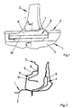
- the floor assembly 1 shows a partial region of a body of a motor vehicle with a floor assembly 1, a passenger compartment and a column 2 arranged vertically as a B-pillar.
- the floor assembly 1 has a floor panel 3 and is projecting outwardly from a longitudinal member 4 limited.
- an inner panel 5 delimiting the longitudinal member 4 inwardly is shown only in FIG.
- the column 2 is connected to the longitudinal member 4.
- a supporting element 6 is fastened at its upper end to the region of the column 2 facing the longitudinal member 4.
- the support member 6 has a flange 7.
- the support member 6 is supported at the bottom of the bottom plate 3 down.
- the lateral ends of the support element 6 are fastened to the side member 4.
- the support element 6 has a deformation element 8.
- the deformation element 8 has a bead 10 arranged parallel to the side rail 4.
- the support member 6 is disposed below the inner panel 5 of the longitudinal member 4 and thus between the inner panel and an outer panel 9.
- the bead 10 of the deformation member 8 protrudes in the direction of the inner panel 5.
- the support member 6 is connected to the components of the longitudinal member 4.
- the support of the support member 6 on the floor panel 3 is not shown in FIG 2 for the simplicity of the drawing.
- the support member 6 stiffens the longitudinal member 4 at a torsional stress. Thus, a particularly uniform load on the body is achieved in a crash.
- the support element 6 thus deliberately reduces deformation forces in the event of a crash.
Landscapes
- Engineering & Computer Science (AREA)
- Chemical & Material Sciences (AREA)
- Combustion & Propulsion (AREA)
- Transportation (AREA)
- Mechanical Engineering (AREA)
- Body Structure For Vehicles (AREA)
- Motor Or Generator Frames (AREA)
Abstract
Description
- Die Erfindung betrifft eine Karosserie für ein Kraftfahrzeug mit einem eine Bodengruppe seitlich begrenzenden Längsträger, mit einem an dem Längsträger befestigten Bodenblech und mit einer sich an dem Längsträger abstützenden, eine Türausnehmung nach hinten begrenzenden Säule.
- Eine solche Karosserie ist beispielsweise aus der
EP 0 844 165 B1 bekannt. Hierbei ist die als B-Säule ausgebildete Säule auf einen Schweller des Längsträgers aufgesetzt und über ein schräg sich an dem Bodenblech abstützendes Verstärkungsblech mit der Bodengruppe verbunden. Der Schweller stützt bei einem Frontalcrash entstehende Kräfte ab, während das Verstärkungsblech bei einem Seitenaufprall Kräfte von der B-Säule in die Bodengruppe einleitet. Hierdurch wird bei einem Crash die Fahrgastzelle des Kraftfahrzeuges weitgehend intakt gehalten. Nachteilig bei der bekannten Karosserie ist jedoch, dass die Anbindung der B-Säule an die Bodengruppe nur sehr schwer zu fertigen ist. Weiterhin weist die Anbindung der B-Säule an die Bodengruppe sehr große Abmessungen auf, was beispielsweise beim Einsatz von hochfesten Stählen zu hohen Kosten führt. - Der Erfindung liegt das Problem zugrunde, eine Karosserie der eingangs genannten Art so weiterzubilden, dass sie eine gleichmäßige Deformation der Karosserie im Crashfall gewährleistet und dass sie möglichst kostengünstig herstellbar ist.
- Dieses Problem wird erfindungsgemäß gelöst durch ein Stützelement, welches sich nach oben hin an dem dem Längsträger zugewandten Bereich der Säule und nach unten hin an dem Bodenblech abstützt.
- Durch diese Gestaltung benötigt die erfindungsgemäße Karosserie mit dem Stützelement nur ein einzelnes Bauteil, welches bei entsprechender Formgebung gleichmäßig und gezielt Deformationskräfte bei einem Crash abbaut. Hierdurch ist die erfindungsgemäße Karosserie konstruktiv besonders einfach aufgebaut und lässt sich kostengünstig fertigen. Weiterhin vermag das Stützelement an dieser Stelle in der erfindungsgemäßen Karosserie ein Tordieren des Schwellers zu verhindern. Daher wird im Crashfall eine gleichmäßige Deformation der Karosserie gewährleistet. Die Größe des Stützelementes kann entsprechend den Abmessungen der angrenzenden Bauteile angepasst werden.
- Zur weiteren Erhöhung der Stabilität der erfindungsgemäßen Karosserie im Bereich des Anschlusses der Säule an dem Längsträger trägt es bei, wenn das Stützelement an einem Innenblech und an einem Außenblech des Längsträgers befestigt ist. Das Stützelement erzeugt damit einen Abstützschott und stützt die äußere Struktur des Längsträgers gegen die innere ab und verhindert damit deren Versagen bei einem Crash.
- Ein Aufbiegen von Flanschen im Anschluss der Säule an dem Längsträger lässt sich gemäß einer vorteilhaften Weiterbildung der Erfindung einfach vermeiden, wenn das Stützelement seitlich an dem Längsträger befestigt ist. Durch die Anlenkung des Stützelementes sowohl an dem Längsträger als auch an dem Bodenblech und der Säule werden zudem Torsionskräfte zuverlässig abgestützt.
- Bei einem Crash des Kraftfahrzeuges lassen sich gemäß einer anderen vorteilhaften Weiterbildung der Erfindung gezielt Deformationskräfte abbauen, wenn das Stützelement in einem mittleren Bereich ein Deformationsglied aufweist und wenn das Deformationsglied in zumindest einer Belastungsrichtung eine geringere Biegesteifheit aufweist als die an das Deformationsglied angrenzenden Bereiche des Stützelementes. Hierdurch wird verhindert, dass das Stützelement bei einem Crash zu einer Überlastung der angrenzenden Bauteile der erfindungsgemäßen Karosserie führt.
- Das Deformationsglied gestaltet sich gemäß einer anderen vorteilhaften Weiterbildung der Erfindung konstruktiv besonders einfach, wenn das Deformationsglied eine Sicke aufweist. Durch diese Gestaltung ermöglicht das Deformationsglied einen gezielten Abbau der Deformationskräfte in einer Richtung. In einer anderen Richtung ist das Deformationsglied relativ steif und verhindert ein Versagen der an das Stützelement angrenzenden Bauteile bei einem Crash.
- In Längsrichtung weist die erfindungsgemäße Karosserie eine besonders hohe Steifheit auf, wenn die Sicke parallel zu dem Längsträger angeordnet ist.
- Eine Störung des Innenraums durch das Stützelement lässt sich gemäß einer anderen vorteilhaften Weiterbildung der Erfindung einfach vermeiden, wenn das Stützelement unterhalb des Innenblechs des Längsträgers angeordnet ist.
- Die Erfindung lässt verschiedene Ausführungsformen zu. Zur weiteren Verdeutlichung ihres Grundprinzips ist eine davon in der Zeichnung dargestellt und wird nachfolgend beschrieben. Die Zeichnung zeigt in
- Fig. 1
- perspektivisch einen Teilbereich einer erfindungsgemäßen Karosserie im Bereich einer Anbindung der B-Säule an eine Bodengruppe,
- Fig. 2
- eine Schnittdarstellung durch einen Teilbereich der erfindungsgemäßen Karosserie aus Figur 1 entlang der Linie II - II.
- Figur 1 zeigt einen Teilbereich einer Karosserie eines Kraftfahrzeuges mit einer Bodengruppe 1, einer Fahrgastzelle und einer vertikal zu der Bodengruppe 1 angeordneten, als B-Säule ausgebildeten Säule 2. Die Bodengruppe 1 weist ein Bodenblech 3 auf und ist nach außen hin von einem Längsträger 4 begrenzt. Zur Vereinfachung der Zeichnung sind ein den Längsträger 4 nach innen hin begrenzendes Innenblech 5 nur in Figur 2 dargestellt. Die Säule 2 ist mit dem Längsträger 4 verbunden. Ein Stützelement 6 ist an seinem oberen Ende an dem dem Längsträger 4 zugewandten Bereich der Säule 2 befestigt. Hierfür hat das Stützelement 6 einen Flansch 7. Weiterhin stützt sich das Stützelement 6 nach unten hin an dem Bodenblech 3 ab. Die seitlichen Enden des Stützelementes 6 sind an dem Längsträger 4 befestigt. Im mittleren Bereich hat das Stützelement 6 ein Deformationsglied 8. Das Deformationsglied 8 hat eine parallel zu dem Längsträger 4 angeordnete Sicke 10.
- wie Figur 2 in einer Schnittdarstellung durch den Teilbereich der Karosserie aus Figur 1 erkennen lässt, ist das Stützelement 6 unterhalb des Innenblechs 5 des Längsträgers 4 und damit zwischen dem Innenblech und einem Außenblech 9 angeordnet. Die Sicke 10 des Deformationsgliedes 8 ragt dabei in Richtung des Innenblechs 5. In dem senkrecht zur zeichenebene weisenden Ende ist das Stützelement 6 mit den Bauteilen des Längsträgers 4 verbunden. Die Abstützung des Stützelementes 6 an dem Bodenblech 3 ist zur Vereinfachung der Zeichnung in Figur 2 nicht dargestellt. Das Stützelement 6 versteift den Längsträger 4 bei einer Torsionsbeanspruchung. Damit wird bei einem Crash eine besonders gleichmäßige Belastung der Karosserie erreicht. Das Stützelement 6 baut damit gezielt Deformationskräfte beim Crash ab.
Claims (7)
- Karosserie für ein Kraftfahrzeug mit einem eine Bodengruppe (1) seitlich begrenzenden Längsträger (4), mit einem an dem Längsträger (4) befestigten Bodenblech (3) und mit einer sich an dem Längsträger (4) abstützenden, eine Türausnehmung nach hinten begrenzenden Säule (2), gekennzeichnet durch ein Stützelement (6), welches sich nach oben hin an dem dem Längsträger (4) zugewandten Bereich der Säule (2) und nach unten hin an dem Bodenblech (3) abstützt.
- Karosserie nach Anspruch 1, dadurch gekennzeichnet, dass das Stützelement (6) an einem Innenblech und an einem Außenblech (9) des Längsträgers (4) befestigt ist.
- Karosserie nach Anspruch 1 oder 2, dadurch gekennzeichnet, dass das Stützelement (6) seitlich an dem Längsträger (4) befestigt ist.
- Karosserie nach zumindest einem der vorhergehenden Ansprüche, dadurch gekennzeichnet, dass das Stützelement (6) in einem mittleren Bereich ein Deformationsglied (8) aufweist und dass das Deformationsglied (8) in zumindest einer Belastungsrichtung eine geringere Biegesteifheit aufweist als die an das Deformationsglied (8) angrenzenden Bereiche des Stützelementes (6).
- Karosserie nach zumindest einem der vorhergehenden Ansprüche, dadurch gekennzeichnet, dass das Deformationsglied (8) eine Sicke (10) aufweist.
- Karosserie nach zumindest einem der vorhergehenden Ansprüche, dadurch gekennzeichnet, dass die Sicke (10) parallel zu dem Längsträger (4) angeordnet ist.
- Karosserie nach zumindest einem der vorhergehenden Ansprüche, dadurch gekennzeichnet, dass das Stützelement (6) unterhalb des Innenblechs (5) des Längsträgers (4) angeordnet ist.
Applications Claiming Priority (1)
| Application Number | Priority Date | Filing Date | Title |
|---|---|---|---|
| DE200610013650 DE102006013650A1 (de) | 2006-03-24 | 2006-03-24 | Karosserie für ein Kraftfahrzeug |
Publications (3)
| Publication Number | Publication Date |
|---|---|
| EP1840009A2 true EP1840009A2 (de) | 2007-10-03 |
| EP1840009A3 EP1840009A3 (de) | 2008-03-12 |
| EP1840009B1 EP1840009B1 (de) | 2012-08-22 |
Family
ID=38191245
Family Applications (1)
| Application Number | Title | Priority Date | Filing Date |
|---|---|---|---|
| EP20070005985 Not-in-force EP1840009B1 (de) | 2006-03-24 | 2007-03-23 | Karosserie für ein Kraftfahrzeug |
Country Status (2)
| Country | Link |
|---|---|
| EP (1) | EP1840009B1 (de) |
| DE (1) | DE102006013650A1 (de) |
Cited By (8)
| Publication number | Priority date | Publication date | Assignee | Title |
|---|---|---|---|---|
| FR2934232A1 (fr) * | 2008-07-28 | 2010-01-29 | Peugeot Citroen Automobiles Sa | Systeme de montage etanche du pied central de la caisse d'un vehicule automobile sur le longeron du soubassement. |
| DE102009012237A1 (de) | 2009-03-07 | 2010-09-09 | Dr. Ing. H.C. F. Porsche Aktiengesellschaft | Karosserie für ein Kraftfahrzeug |
| CN102114869A (zh) * | 2010-08-17 | 2011-07-06 | 浙江吉利汽车研究院有限公司 | 汽车发动机舱纵梁与立柱安装结构 |
| FR2989051A1 (fr) * | 2012-04-05 | 2013-10-11 | Peugeot Citroen Automobiles Sa | Caisse de vehicule automobile comprenant un renfort de pied milieu elargi. |
| EP2623399A4 (de) * | 2010-09-28 | 2014-04-16 | Toyota Motor Co Ltd | Fahrzeugaufbaukonstruktion |
| CN106891999A (zh) * | 2015-12-17 | 2017-06-27 | 北汽福田汽车股份有限公司 | 车身门框结构、车辆和车身门框结构的制造方法 |
| CN109760751A (zh) * | 2017-11-10 | 2019-05-17 | 本特勒尔汽车技术有限公司 | 用于汽车的带有支撑柱的装置 |
| CN112793671A (zh) * | 2021-01-27 | 2021-05-14 | 浙江零跑科技有限公司 | 一种多传力途径的b柱下接头结构 |
Families Citing this family (5)
| Publication number | Priority date | Publication date | Assignee | Title |
|---|---|---|---|---|
| DE102009006875B4 (de) * | 2009-01-31 | 2019-05-23 | Dr. Ing. H.C. F. Porsche Aktiengesellschaft | Karosserieseitenstruktur eines Kraftfahrzeugs |
| DE102010001231B4 (de) * | 2010-01-26 | 2019-07-04 | Deutsches Zentrum für Luft- und Raumfahrt e.V. | Struktureinrichtung für ein Fahrzeug |
| DE102011055342B4 (de) * | 2011-11-15 | 2021-05-06 | Dr. Ing. H.C. F. Porsche Aktiengesellschaft | Karosserieseitenstruktur |
| DE102012004501B4 (de) * | 2012-03-05 | 2015-07-30 | Audi Ag | Säulenstruktur für eine Fahrzeugkarosserie |
| DE102013224056B4 (de) | 2012-11-30 | 2025-07-10 | Deutsches Zentrum für Luft- und Raumfahrt e.V. | Tragende Struktur und Fahrzeug |
Citations (4)
| Publication number | Priority date | Publication date | Assignee | Title |
|---|---|---|---|---|
| JPH06211164A (ja) | 1993-01-14 | 1994-08-02 | Toyota Motor Corp | 車体の側部構造 |
| US5388885A (en) | 1993-02-01 | 1995-02-14 | General Motors Corporation | Body structure of a motor vehicle |
| US5820204A (en) | 1994-08-31 | 1998-10-13 | Fuji Jukogyo Kabushiki Kaisha | Body structure for a motor vehicle |
| EP0844165B1 (de) | 1996-11-14 | 2002-01-30 | Adam Opel Ag | Bodengruppe für eine Kraftfahrzeugkarosserie |
-
2006
- 2006-03-24 DE DE200610013650 patent/DE102006013650A1/de not_active Withdrawn
-
2007
- 2007-03-23 EP EP20070005985 patent/EP1840009B1/de not_active Not-in-force
Patent Citations (4)
| Publication number | Priority date | Publication date | Assignee | Title |
|---|---|---|---|---|
| JPH06211164A (ja) | 1993-01-14 | 1994-08-02 | Toyota Motor Corp | 車体の側部構造 |
| US5388885A (en) | 1993-02-01 | 1995-02-14 | General Motors Corporation | Body structure of a motor vehicle |
| US5820204A (en) | 1994-08-31 | 1998-10-13 | Fuji Jukogyo Kabushiki Kaisha | Body structure for a motor vehicle |
| EP0844165B1 (de) | 1996-11-14 | 2002-01-30 | Adam Opel Ag | Bodengruppe für eine Kraftfahrzeugkarosserie |
Cited By (10)
| Publication number | Priority date | Publication date | Assignee | Title |
|---|---|---|---|---|
| FR2934232A1 (fr) * | 2008-07-28 | 2010-01-29 | Peugeot Citroen Automobiles Sa | Systeme de montage etanche du pied central de la caisse d'un vehicule automobile sur le longeron du soubassement. |
| DE102009012237A1 (de) | 2009-03-07 | 2010-09-09 | Dr. Ing. H.C. F. Porsche Aktiengesellschaft | Karosserie für ein Kraftfahrzeug |
| DE102009012237B4 (de) | 2009-03-07 | 2019-03-07 | Dr. Ing. H.C. F. Porsche Aktiengesellschaft | Karosserie für ein Kraftfahrzeug |
| CN102114869A (zh) * | 2010-08-17 | 2011-07-06 | 浙江吉利汽车研究院有限公司 | 汽车发动机舱纵梁与立柱安装结构 |
| EP2623399A4 (de) * | 2010-09-28 | 2014-04-16 | Toyota Motor Co Ltd | Fahrzeugaufbaukonstruktion |
| FR2989051A1 (fr) * | 2012-04-05 | 2013-10-11 | Peugeot Citroen Automobiles Sa | Caisse de vehicule automobile comprenant un renfort de pied milieu elargi. |
| CN106891999A (zh) * | 2015-12-17 | 2017-06-27 | 北汽福田汽车股份有限公司 | 车身门框结构、车辆和车身门框结构的制造方法 |
| CN106891999B (zh) * | 2015-12-17 | 2020-01-17 | 北京宝沃汽车有限公司 | 车身门框结构、车辆和车身门框结构的制造方法 |
| CN109760751A (zh) * | 2017-11-10 | 2019-05-17 | 本特勒尔汽车技术有限公司 | 用于汽车的带有支撑柱的装置 |
| CN112793671A (zh) * | 2021-01-27 | 2021-05-14 | 浙江零跑科技有限公司 | 一种多传力途径的b柱下接头结构 |
Also Published As
| Publication number | Publication date |
|---|---|
| DE102006013650A1 (de) | 2007-10-11 |
| EP1840009A3 (de) | 2008-03-12 |
| EP1840009B1 (de) | 2012-08-22 |
Similar Documents
| Publication | Publication Date | Title |
|---|---|---|
| EP1840009B1 (de) | Karosserie für ein Kraftfahrzeug | |
| DE69825711T2 (de) | Fahrerhaus für eine Baumaschine | |
| EP1829767B1 (de) | Hilfsrahmen zur Befestigung an einer Karosserie eines Kraftwagens | |
| DE102011081095B4 (de) | Längslenkerbefestigungsstruktur | |
| DE10232841A1 (de) | Bodenträgeranordnung an Kraftfahrzeugen | |
| DE102019134712B4 (de) | Karosserieteilstruktur für ein wenigstens teilweise batteriebetriebenes Kraftfahrzeug | |
| DE102007041382B4 (de) | Reserveradmulde für ein Kraftfahrzeug | |
| DE10232842A1 (de) | Bodenversteifungsstruktur an Kraftfahrzeugen | |
| DE102008056501B4 (de) | Kraftfahrzeugkarosserie | |
| DE10220796A1 (de) | Karosserie für ein Kraftfahrzeug | |
| DE102011002964A1 (de) | Lagerung eines Querstabilisators an einem rahmenartigen Achsträger eines zweispurigen Fahrzeugs | |
| DE102006033990A1 (de) | Kraftfahrzeug mit einer Längs- und Querträger aufweisenden Tragstruktur | |
| EP1314632B1 (de) | Karosserie mit rahmenartigem Achsträger | |
| DE10119131A1 (de) | Fahrzeugtür mit einer Crashabstützung | |
| EP1488986B1 (de) | Kraftfahrzeug mit einer Verbindungsanordnung im Dachbereich | |
| EP1632422B1 (de) | Karosserie für ein Kraftfahrzeug | |
| DE102005018830B3 (de) | Rahmenkonstruktion zur Aufnahme eines schwenkbar gelagerten Fahrerhauses eines Lastkraftwagens | |
| EP1449746B1 (de) | Kraftfahrzeugkarosserie mit Verstärkungsblech zwischen Dachspriegel, Säule und Seitenwand | |
| EP0555744B1 (de) | Radeinbau an Karosserien für Kraftfahrzeuge | |
| DE102005061295A1 (de) | Türstruktur | |
| DE102012015334B4 (de) | Befestigungsanordnung einer Versteifungsstrebe an einem Windschutzscheiben-Querträger | |
| DE102004003193B4 (de) | Fahrerhaus für ein Nutzfahrzeug | |
| DE102008027199B4 (de) | Queraussteifungsstruktur für ein Kraftfahrzeug | |
| DE102006039032B4 (de) | Stützanordnung für eine Kraftwagenkarosserie | |
| DE102006015415B4 (de) | Karosserie für einen Personenkraftwagen |
Legal Events
| Date | Code | Title | Description |
|---|---|---|---|
| PUAI | Public reference made under article 153(3) epc to a published international application that has entered the european phase |
Free format text: ORIGINAL CODE: 0009012 |
|
| AK | Designated contracting states |
Kind code of ref document: A2 Designated state(s): AT BE BG CH CY CZ DE DK EE ES FI FR GB GR HU IE IS IT LI LT LU LV MC MT NL PL PT RO SE SI SK TR |
|
| AX | Request for extension of the european patent |
Extension state: AL BA HR MK YU |
|
| PUAL | Search report despatched |
Free format text: ORIGINAL CODE: 0009013 |
|
| AK | Designated contracting states |
Kind code of ref document: A3 Designated state(s): AT BE BG CH CY CZ DE DK EE ES FI FR GB GR HU IE IS IT LI LT LU LV MC MT NL PL PT RO SE SI SK TR |
|
| AX | Request for extension of the european patent |
Extension state: AL BA HR MK YU |
|
| 17P | Request for examination filed |
Effective date: 20080912 |
|
| 17Q | First examination report despatched |
Effective date: 20081010 |
|
| AKX | Designation fees paid |
Designated state(s): AT BE BG CH CY CZ DE DK EE ES FI FR GB GR HU IE IS IT LI LT LU LV MC MT NL PL PT RO SE SI SK TR |
|
| RAP1 | Party data changed (applicant data changed or rights of an application transferred) |
Owner name: GM GLOBAL TECHNOLOGY OPERATIONS LLC |
|
| GRAP | Despatch of communication of intention to grant a patent |
Free format text: ORIGINAL CODE: EPIDOSNIGR1 |
|
| GRAS | Grant fee paid |
Free format text: ORIGINAL CODE: EPIDOSNIGR3 |
|
| GRAA | (expected) grant |
Free format text: ORIGINAL CODE: 0009210 |
|
| AK | Designated contracting states |
Kind code of ref document: B1 Designated state(s): AT BE BG CH CY CZ DE DK EE ES FI FR GB GR HU IE IS IT LI LT LU LV MC MT NL PL PT RO SE SI SK TR |
|
| REG | Reference to a national code |
Ref country code: GB Ref legal event code: FG4D Free format text: NOT ENGLISH |
|
| REG | Reference to a national code |
Ref country code: CH Ref legal event code: EP |
|
| REG | Reference to a national code |
Ref country code: IE Ref legal event code: FG4D Free format text: LANGUAGE OF EP DOCUMENT: GERMAN |
|
| REG | Reference to a national code |
Ref country code: AT Ref legal event code: REF Ref document number: 571811 Country of ref document: AT Kind code of ref document: T Effective date: 20120915 |
|
| REG | Reference to a national code |
Ref country code: DE Ref legal event code: R096 Ref document number: 502007010407 Country of ref document: DE Effective date: 20121018 |
|
| REG | Reference to a national code |
Ref country code: NL Ref legal event code: VDEP Effective date: 20120822 |
|
| REG | Reference to a national code |
Ref country code: LT Ref legal event code: MG4D Effective date: 20120822 |
|
| PG25 | Lapsed in a contracting state [announced via postgrant information from national office to epo] |
Ref country code: IS Free format text: LAPSE BECAUSE OF FAILURE TO SUBMIT A TRANSLATION OF THE DESCRIPTION OR TO PAY THE FEE WITHIN THE PRESCRIBED TIME-LIMIT Effective date: 20121222 Ref country code: CY Free format text: LAPSE BECAUSE OF FAILURE TO SUBMIT A TRANSLATION OF THE DESCRIPTION OR TO PAY THE FEE WITHIN THE PRESCRIBED TIME-LIMIT Effective date: 20120822 Ref country code: LT Free format text: LAPSE BECAUSE OF FAILURE TO SUBMIT A TRANSLATION OF THE DESCRIPTION OR TO PAY THE FEE WITHIN THE PRESCRIBED TIME-LIMIT Effective date: 20120822 Ref country code: FI Free format text: LAPSE BECAUSE OF FAILURE TO SUBMIT A TRANSLATION OF THE DESCRIPTION OR TO PAY THE FEE WITHIN THE PRESCRIBED TIME-LIMIT Effective date: 20120822 |
|
| PG25 | Lapsed in a contracting state [announced via postgrant information from national office to epo] |
Ref country code: GR Free format text: LAPSE BECAUSE OF FAILURE TO SUBMIT A TRANSLATION OF THE DESCRIPTION OR TO PAY THE FEE WITHIN THE PRESCRIBED TIME-LIMIT Effective date: 20121123 Ref country code: PT Free format text: LAPSE BECAUSE OF FAILURE TO SUBMIT A TRANSLATION OF THE DESCRIPTION OR TO PAY THE FEE WITHIN THE PRESCRIBED TIME-LIMIT Effective date: 20121224 Ref country code: LV Free format text: LAPSE BECAUSE OF FAILURE TO SUBMIT A TRANSLATION OF THE DESCRIPTION OR TO PAY THE FEE WITHIN THE PRESCRIBED TIME-LIMIT Effective date: 20120822 Ref country code: SI Free format text: LAPSE BECAUSE OF FAILURE TO SUBMIT A TRANSLATION OF THE DESCRIPTION OR TO PAY THE FEE WITHIN THE PRESCRIBED TIME-LIMIT Effective date: 20120822 Ref country code: SE Free format text: LAPSE BECAUSE OF FAILURE TO SUBMIT A TRANSLATION OF THE DESCRIPTION OR TO PAY THE FEE WITHIN THE PRESCRIBED TIME-LIMIT Effective date: 20120822 |
|
| PG25 | Lapsed in a contracting state [announced via postgrant information from national office to epo] |
Ref country code: NL Free format text: LAPSE BECAUSE OF FAILURE TO SUBMIT A TRANSLATION OF THE DESCRIPTION OR TO PAY THE FEE WITHIN THE PRESCRIBED TIME-LIMIT Effective date: 20120822 |
|
| PG25 | Lapsed in a contracting state [announced via postgrant information from national office to epo] |
Ref country code: DK Free format text: LAPSE BECAUSE OF FAILURE TO SUBMIT A TRANSLATION OF THE DESCRIPTION OR TO PAY THE FEE WITHIN THE PRESCRIBED TIME-LIMIT Effective date: 20120822 Ref country code: CZ Free format text: LAPSE BECAUSE OF FAILURE TO SUBMIT A TRANSLATION OF THE DESCRIPTION OR TO PAY THE FEE WITHIN THE PRESCRIBED TIME-LIMIT Effective date: 20120822 Ref country code: RO Free format text: LAPSE BECAUSE OF FAILURE TO SUBMIT A TRANSLATION OF THE DESCRIPTION OR TO PAY THE FEE WITHIN THE PRESCRIBED TIME-LIMIT Effective date: 20120822 Ref country code: ES Free format text: LAPSE BECAUSE OF FAILURE TO SUBMIT A TRANSLATION OF THE DESCRIPTION OR TO PAY THE FEE WITHIN THE PRESCRIBED TIME-LIMIT Effective date: 20121203 Ref country code: EE Free format text: LAPSE BECAUSE OF FAILURE TO SUBMIT A TRANSLATION OF THE DESCRIPTION OR TO PAY THE FEE WITHIN THE PRESCRIBED TIME-LIMIT Effective date: 20120822 |
|
| PGFP | Annual fee paid to national office [announced via postgrant information from national office to epo] |
Ref country code: GB Payment date: 20130320 Year of fee payment: 7 Ref country code: FR Payment date: 20130325 Year of fee payment: 7 Ref country code: DE Payment date: 20130320 Year of fee payment: 7 |
|
| PG25 | Lapsed in a contracting state [announced via postgrant information from national office to epo] |
Ref country code: PL Free format text: LAPSE BECAUSE OF FAILURE TO SUBMIT A TRANSLATION OF THE DESCRIPTION OR TO PAY THE FEE WITHIN THE PRESCRIBED TIME-LIMIT Effective date: 20120822 Ref country code: SK Free format text: LAPSE BECAUSE OF FAILURE TO SUBMIT A TRANSLATION OF THE DESCRIPTION OR TO PAY THE FEE WITHIN THE PRESCRIBED TIME-LIMIT Effective date: 20120822 Ref country code: IT Free format text: LAPSE BECAUSE OF FAILURE TO SUBMIT A TRANSLATION OF THE DESCRIPTION OR TO PAY THE FEE WITHIN THE PRESCRIBED TIME-LIMIT Effective date: 20120822 |
|
| PLBE | No opposition filed within time limit |
Free format text: ORIGINAL CODE: 0009261 |
|
| STAA | Information on the status of an ep patent application or granted ep patent |
Free format text: STATUS: NO OPPOSITION FILED WITHIN TIME LIMIT |
|
| 26N | No opposition filed |
Effective date: 20130523 |
|
| PG25 | Lapsed in a contracting state [announced via postgrant information from national office to epo] |
Ref country code: BG Free format text: LAPSE BECAUSE OF FAILURE TO SUBMIT A TRANSLATION OF THE DESCRIPTION OR TO PAY THE FEE WITHIN THE PRESCRIBED TIME-LIMIT Effective date: 20121122 |
|
| REG | Reference to a national code |
Ref country code: DE Ref legal event code: R097 Ref document number: 502007010407 Country of ref document: DE Effective date: 20130523 |
|
| BERE | Be: lapsed |
Owner name: GM GLOBAL TECHNOLOGY OPERATIONS LLC Effective date: 20130331 |
|
| PG25 | Lapsed in a contracting state [announced via postgrant information from national office to epo] |
Ref country code: MC Free format text: LAPSE BECAUSE OF NON-PAYMENT OF DUE FEES Effective date: 20130331 |
|
| REG | Reference to a national code |
Ref country code: CH Ref legal event code: PL |
|
| REG | Reference to a national code |
Ref country code: IE Ref legal event code: MM4A |
|
| PG25 | Lapsed in a contracting state [announced via postgrant information from national office to epo] |
Ref country code: IE Free format text: LAPSE BECAUSE OF NON-PAYMENT OF DUE FEES Effective date: 20130323 Ref country code: CH Free format text: LAPSE BECAUSE OF NON-PAYMENT OF DUE FEES Effective date: 20130331 Ref country code: LI Free format text: LAPSE BECAUSE OF NON-PAYMENT OF DUE FEES Effective date: 20130331 Ref country code: BE Free format text: LAPSE BECAUSE OF NON-PAYMENT OF DUE FEES Effective date: 20130331 |
|
| REG | Reference to a national code |
Ref country code: AT Ref legal event code: MM01 Ref document number: 571811 Country of ref document: AT Kind code of ref document: T Effective date: 20130323 |
|
| PG25 | Lapsed in a contracting state [announced via postgrant information from national office to epo] |
Ref country code: MT Free format text: LAPSE BECAUSE OF FAILURE TO SUBMIT A TRANSLATION OF THE DESCRIPTION OR TO PAY THE FEE WITHIN THE PRESCRIBED TIME-LIMIT Effective date: 20120822 |
|
| PG25 | Lapsed in a contracting state [announced via postgrant information from national office to epo] |
Ref country code: AT Free format text: LAPSE BECAUSE OF NON-PAYMENT OF DUE FEES Effective date: 20130323 |
|
| REG | Reference to a national code |
Ref country code: DE Ref legal event code: R119 Ref document number: 502007010407 Country of ref document: DE |
|
| GBPC | Gb: european patent ceased through non-payment of renewal fee |
Effective date: 20140323 |
|
| REG | Reference to a national code |
Ref country code: FR Ref legal event code: ST Effective date: 20141128 |
|
| REG | Reference to a national code |
Ref country code: DE Ref legal event code: R119 Ref document number: 502007010407 Country of ref document: DE Effective date: 20141001 |
|
| PG25 | Lapsed in a contracting state [announced via postgrant information from national office to epo] |
Ref country code: GB Free format text: LAPSE BECAUSE OF NON-PAYMENT OF DUE FEES Effective date: 20140323 Ref country code: DE Free format text: LAPSE BECAUSE OF NON-PAYMENT OF DUE FEES Effective date: 20141001 Ref country code: FR Free format text: LAPSE BECAUSE OF NON-PAYMENT OF DUE FEES Effective date: 20140331 |
|
| PG25 | Lapsed in a contracting state [announced via postgrant information from national office to epo] |
Ref country code: TR Free format text: LAPSE BECAUSE OF FAILURE TO SUBMIT A TRANSLATION OF THE DESCRIPTION OR TO PAY THE FEE WITHIN THE PRESCRIBED TIME-LIMIT Effective date: 20120822 |
|
| PG25 | Lapsed in a contracting state [announced via postgrant information from national office to epo] |
Ref country code: HU Free format text: LAPSE BECAUSE OF FAILURE TO SUBMIT A TRANSLATION OF THE DESCRIPTION OR TO PAY THE FEE WITHIN THE PRESCRIBED TIME-LIMIT; INVALID AB INITIO Effective date: 20070323 Ref country code: LU Free format text: LAPSE BECAUSE OF NON-PAYMENT OF DUE FEES Effective date: 20130323 |