EP1839604A1 - Dispositif destiné à l'exécution de recherches et opérations chirurgicales de l'utérus - Google Patents
Dispositif destiné à l'exécution de recherches et opérations chirurgicales de l'utérus Download PDFInfo
- Publication number
- EP1839604A1 EP1839604A1 EP07006115A EP07006115A EP1839604A1 EP 1839604 A1 EP1839604 A1 EP 1839604A1 EP 07006115 A EP07006115 A EP 07006115A EP 07006115 A EP07006115 A EP 07006115A EP 1839604 A1 EP1839604 A1 EP 1839604A1
- Authority
- EP
- European Patent Office
- Prior art keywords
- handle
- extension
- jaw
- sliding sleeve
- ring
- Prior art date
- Legal status (The legal status is an assumption and is not a legal conclusion. Google has not performed a legal analysis and makes no representation as to the accuracy of the status listed.)
- Granted
Links
- 210000004291 uterus Anatomy 0.000 title claims description 16
- 210000003813 thumb Anatomy 0.000 claims description 12
- 230000007246 mechanism Effects 0.000 claims description 10
- 238000001356 surgical procedure Methods 0.000 claims description 6
- 238000006073 displacement reaction Methods 0.000 claims description 5
- 230000008901 benefit Effects 0.000 description 20
- 210000001215 vagina Anatomy 0.000 description 18
- 210000003679 cervix uteri Anatomy 0.000 description 13
- 210000003811 finger Anatomy 0.000 description 8
- 230000000007 visual effect Effects 0.000 description 5
- 238000003780 insertion Methods 0.000 description 3
- 230000037431 insertion Effects 0.000 description 3
- 238000002357 laparoscopic surgery Methods 0.000 description 3
- 238000001839 endoscopy Methods 0.000 description 2
- 230000008921 facial expression Effects 0.000 description 2
- 210000004247 hand Anatomy 0.000 description 2
- 239000003550 marker Substances 0.000 description 2
- 208000025865 Ulcer Diseases 0.000 description 1
- 210000001015 abdomen Anatomy 0.000 description 1
- 210000003484 anatomy Anatomy 0.000 description 1
- 208000031513 cyst Diseases 0.000 description 1
- 238000011010 flushing procedure Methods 0.000 description 1
- 238000009802 hysterectomy Methods 0.000 description 1
- 239000007788 liquid Substances 0.000 description 1
- 238000000034 method Methods 0.000 description 1
- 230000008569 process Effects 0.000 description 1
- 238000007789 sealing Methods 0.000 description 1
- 230000007480 spreading Effects 0.000 description 1
- 238000011477 surgical intervention Methods 0.000 description 1
- 230000007704 transition Effects 0.000 description 1
- 231100000397 ulcer Toxicity 0.000 description 1
Images


Classifications
-
- A—HUMAN NECESSITIES
- A61—MEDICAL OR VETERINARY SCIENCE; HYGIENE
- A61B—DIAGNOSIS; SURGERY; IDENTIFICATION
- A61B17/00—Surgical instruments, devices or methods, e.g. tourniquets
- A61B17/42—Gynaecological or obstetrical instruments or methods
- A61B17/4241—Instruments for manoeuvring or retracting the uterus, e.g. during laparoscopic surgery
-
- A—HUMAN NECESSITIES
- A61—MEDICAL OR VETERINARY SCIENCE; HYGIENE
- A61B—DIAGNOSIS; SURGERY; IDENTIFICATION
- A61B17/00—Surgical instruments, devices or methods, e.g. tourniquets
- A61B17/28—Surgical forceps
- A61B17/29—Forceps for use in minimally invasive surgery
- A61B17/2909—Handles
- A61B2017/2912—Handles transmission of forces to actuating rod or piston
-
- A—HUMAN NECESSITIES
- A61—MEDICAL OR VETERINARY SCIENCE; HYGIENE
- A61B—DIAGNOSIS; SURGERY; IDENTIFICATION
- A61B17/00—Surgical instruments, devices or methods, e.g. tourniquets
- A61B17/28—Surgical forceps
- A61B17/29—Forceps for use in minimally invasive surgery
- A61B2017/2946—Locking means
-
- A—HUMAN NECESSITIES
- A61—MEDICAL OR VETERINARY SCIENCE; HYGIENE
- A61B—DIAGNOSIS; SURGERY; IDENTIFICATION
- A61B17/00—Surgical instruments, devices or methods, e.g. tourniquets
- A61B17/42—Gynaecological or obstetrical instruments or methods
- A61B2017/4216—Operations on uterus, e.g. endometrium
Definitions
- the invention relates to a device for performing examinations and surgical interventions on the uterus, having a body from the distal end of which protrudes an extension which can be introduced into a cervical canal, with an adjustable jaw part for fixing cervical tissue between the extension and the jaw part, and with a handle for adjusting the jaw part.
- Such a device in the form of a uterine forceps is from the catalog of Karl Storz GmbH & Co. KG, Tuttlingen, "STORZ, THE WORLD OF ENDOSCOPY, LAPAROSCOPY" 5th edition 1/2005, page 328 (Device No. 26168 QN).
- Such devices are used in the medical field for the examination and performance of surgical procedures on the uterus.
- the extension which is arranged at a distal end of the device, is inserted through the vagina into the cervical canal. With the extension located in the cervical canal, the uterus is mobilized. If a flushing channel is additionally provided, the uterus can be rinsed. Examinations and other manipulations are performed by another device, such as a hysterectomy.
- a uterine manipulator known model CLERMONT-FERRAND is a uterine manipulator known model CLERMONT-FERRAND.
- This uterine manipulator consists of an approximately rod-shaped body. At the proximal end of a pivoting handle with a hand-to-grip handle is arranged. At the distal end a pivotable extension is arranged. The extension and the grip tab are connected to one another in such a way that pivoting the grip tab causes the extension to pivot. With a second hand, the uterine manipulator is gripped either on its body or on a laterally projecting rod to thereby hold the approximately 50 cm long manipulator.
- the desired angled position of the extension relative to the elongated body is adjusted by the grip tab and can be locked via a residual mechanism in five locking positions between 0 ° and 90 °.
- vault identification can also be performed by moving the manipulator rod proximally.
- the uterine manipulator is also equipped with a sealing system that prevents leakage of CO 2 introduced into the uterus after opening the vaginal vault.
- This uterine manipulator is very expansive, very long and requires both hands to handle.
- this uterine manipulator is limited to the manipulation of the uterus and identification of the vault.
- large devices have to be guided through the vagina to the uterus in addition to the uterine manipulator. This is very uncomfortable for the patient, and is also unwieldy for the doctor to perform, since he has two devices to operate simultaneously.
- the device mentioned above is a uterus forceps according to QUINONES-NEUBÜSER for laparoscopy and for perturbation.
- the body is formed as a scissor-like forceps, at the proximal end of a handle is arranged.
- the handle parts of the handle which are designed as two finger lugs, are connected via a lock.
- One of the jaw parts arranged at the distal end is designed as a toothed jaw part.
- the second jaw part carries the extension.
- a channel is present in this jaw part, whose distal end carries the extension. The channel is curved due to the pincer-like shapes of the body and must be guided over the hinge, around which the two scissor or pliers parts are pivotable.
- the pincer-like body of the uterine forceps does not conform to the anatomical shape of the vagina so that it is very difficult to guide through the vagina to the cervix.
- the handle of the uterine forceps is gripped by two fingers and can be actuated by pivoting the two handle parts about the hinge axis.
- the scissor-like grip parts gripped by the two fingers obstruct the operator a large area of the field of view. Due to the pincer-like design of the uterine forceps, it is hardly possible, the jamming jaw independently of the To move jaw part with the extension or vice versa. Thereby, the desired positioning of the extension, through which the uterus is to be rinsed or pertubiert, difficult to perform.
- the object is achieved in that the body is designed as an approximately rod-shaped body, and that the handle is arranged on the body, that it is actuated by a, the body engaging hand.
- the rod-shaped body can be grasped by a human hand.
- the palm of your hand and the fingers closed around the rod-shaped Body.
- the body is not only very strong and secure to touch, this also takes little space touching.
- the field of view is considerably less affected by a rod-shaped body grasped by a hand than when gripping a scissor handle with finger-eyes.
- the handle for moving the jaw part is arranged on the body so that it can be removed by hand, e.g. from a finger, which has seized the body, is actuated. The body still remains gripped by the hand, so it is firm and secure to hold. This allows the handling of the device with one hand.
- the operator can gently insert the rod-shaped body gripped by a hand into the vagina, while the jaw part is initially placed tightly on the extension via the handle.
- the extension extends distally away from the rod-shaped body and forms a rigid unit with this.
- the extension is in contrast to the above-mentioned prior art no moving or pivoting component. Thus, it can be specifically introduced through the vagina and brought to the cervix.
- the jaw member Before inserting the appendage into the cervix, the jaw member may be moved slightly laterally away from the appendage.
- the jaw part After insertion of the extension into the cervix, the jaw part is moved to fix the position, whereby tissue of the cervix is clamped between extension and jaw part.
- a channel passing therethrough is present in the body.
- This measure has the advantage that a further additional medical instrument can be introduced and passed through the channel passing through the body, e.g. an endoscope.
- the body has a handle on the proximal side and a rod on the distal side, between which the handle is arranged.
- This measure has the advantage that a particularly slender design adapted to the anatomy of the vagina is provided, that is, the device can be introduced atraumatically for the patient.
- the handling of the handling person is very ergonomic, because the device can be inserted into the vagina via the distal rod, the handle and the handle remain outside the body.
- the handle of a hand which has detected the body or the handle, actuated by turning and / or pushing and / or pressing an element.
- This measure has the advantage that the control of the movement of the jaw part can be accomplished by a particularly ergonomic design, namely by a rotational and / or pushing and / or pushing movement of the handle.
- the device can still be held by the hand grasping it, so that the movement of the jaw requires only one hand.
- the element of the handle of a thumb of the gripping hand is actuated.
- This measure has the advantage that only the thumb must be used to control the movement of the jaw part, the palm and the remaining fingers are still available to hold the device.
- the element is designed as a ring element.
- This measure has the advantage that such an element, without visual contact or high concentration, can be grasped by a finger, for example by the thumb, and moved in accordance with the manipulations.
- a trough for inserting the thumb is formed in the ring element.
- This measure has the considerable advantage that the trough can be felt by the thumb easily and without visual contact, and after the thumb is placed in the trough, a secure fit is ensured to operate the handle.
- the handle is in operative connection with the jaw member such that rotation of the handle causes pivoting of the jaw member.
- the handle is operatively connected to a helical groove of a sliding sleeve, so that a rotation of the handle causes an axial displacement of the sliding sleeve along the body.
- This measure has the advantage that a rotational movement of the handle can be converted into an axial displacement of the sliding sleeve in a mechanically very simple manner, which can be safely guided again along the rod-shaped body.
- the sliding sleeve is then corresponding to the jaw in connection.
- the sliding sleeve is connected to an actuating element which converts a linear movement of the sliding sleeve into a pivoting movement of the jaw part directed towards or away from the extension.
- This measure has the considerable advantage that measures taken by little room can be implemented the linear movement of the sleeve in a pivoting movement of the jaw part.
- the actuating element can be guided along the rod-shaped body to the jaw part.
- the actuating element is connected on the distal side with a ring, which is pivotable about an axis extending transversely to the longitudinal axis of the body, wherein the ring carries the distally projecting jaw part.
- two opposing adjustable jaw parts are present.
- tissue of the cervix between the jaw part and extension can be clamped by the opposing jaw parts in two places, so that the device is held firmly and securely.
- This also provides the opportunity to release the device by hand, and to prepare and accomplish with both hands other manipulations or, for example, the insertion of further instruments through the device.
- two rings pivotable about a common axis are provided, each of which carries a jaw member and each of the rings is connected via an actuating element with the sliding sleeve.
- This measure has the advantage that the two jaw parts can be pivoted synchronously and both mouth parts can be pivoted simultaneously by the linear displacement of the sliding sleeve via the actuating elements.
- the rings are then arranged concentrically and pivotable about a common axis.
- This measure has the advantage that a space-saving compact design can be achieved at the distal end region of the device.
- the handle is provided with a latching mechanism, via which the handle and thus a jaw member in a certain position relative to the extension can be latched.
- This measure has the advantage that the jaw parts can be locked in certain pivoting positions, so that, for example, when tissue is clamped sufficiently firmly between jaw part and extension, this position is maintained via the latching mechanism. This allows the operator to release the device, as previously mentioned, to perform other manipulations.
- the latching mechanism on a detent, which is arranged in the handle.
- This measure has the advantage that the catch can be ergonomically operated the same as the handle, for example, by the thumb of a hand that has grasped the device.
- the extension is formed as a cone through which the channel passes.
- This measure has the advantage that over the distal outlet opening of the cone and thus of the channel more instruments can be passed through the device quite specifically.
- the cone facilitates insertion into the cervical canal.
- a jaw part has at least one tip facing the extension.
- This measure has the advantage that the tissue between the jaw part and extension can be kept particularly tight by the tips.
- the or the jaw parts are pivotable relative to the stationary extension.
- This measure has the advantage that the projection remains in place when the jaw parts are actuated, for example already inserted into the cervical canal, and only the jaw parts move relative thereto. This also contributes to a simple and safe handling.
- a mark is present on the body and on the handle movable relative thereto, whose relative position to one another indicates the respective pivoting position of the at least one jaw part with respect to the extension.
- This measure has the considerable advantage that the operator is shown how far away or how close a jaw part is on the extension.
- the distal end region at the end of the vagina is at the transition to the uterus, an area that is difficult to see.
- the markers now give the operator a feeling of how far the jaws are moved that he is doing can see relatively poorly, so that a fixation of the device on the cervical tissue can be performed atraumatic, so that there is no risk that the jaw parts are driven too deep into the tissue and injure this.
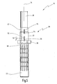
- the device 10 has a rod-shaped body 12, from the distal end 14 of which an extension 16 protrudes.
- the extension 16 is formed as a cone 18.
- a proximal end region 20, just over about one third of the total length of the device 10, is formed as a handle 22.
- a notch pattern 24 is cut, so that the device 10 can be firmly and securely grasped by a human hand in the region of the handle 24.
- the remaining body 12 is formed as a rod 26, the outside of which is smooth.
- the rod 26 has an extension 78, in which, as will be explained in more detail below, further components are accommodated.
- a handle 28 is arranged between rod 26 and handle 22.
- the handle 28 serves to move two jaw parts 30 and 31 arranged opposite one another at the distal end 14 of the rod 26.
- Fig. 1 a position is shown in which the jaws 30, 31 are spread apart or pivoted from the extension 16 a maximum. By pressing the handle 28, the two jaw members 30 and 31 can be moved so far on the extension 16 or pivoted until they touch this about.
- a channel 32 passes centrally whose central longitudinal axis corresponds to the longitudinal axis 34 of the device 10 (FIG. 3).
- the handle 28 has a ring member 36 whose outer diameter is slightly larger than the outer diameter of the handle 22 (Fig. 3).
- a recess 38 is recessed, which serves that a thumb of a human hand, which has grasped the handle 22, can be inserted into the recess 38 of the ring member 36.
- a sleeve 40 which surrounds a partially received in this sliding sleeve 42.
- the sliding sleeve 42 has on its outer side a helical groove 44 in which a radially inwardly projecting from the sleeve 40 of the ring member 36 pin 46 runs.
- the sliding sleeve 42 is slid longitudinally displaceable on the outside of the rod 26. From the inside of the handle 28, there are bolts 51 which engage in a circumferential annular groove of the body 12, which is not described here in detail.
- latching grooves 48 are cut on the outer side of the sliding sleeve 42 in which a catch 50 engages.
- the catch 50 is designed as a two-armed lever 52, as can be seen in particular from FIG. 5, which is pivotable or tiltable about an axis 54 transversely to the longitudinal axis 34 of the device 10.
- One arm of the lever 52 carries the detent 50 which engages with the notches 48, the opposite arm of the lever 52 has a pusher 56 projecting radially outward.
- This latching mechanism 60 can be actuated by the same finger, for example the thumb, which also rotates the ring element 36. For this purpose, it is pressed on the pusher 56, so that then the lever 52 is pivoted against the force of a spring not shown here so that the catch 50 disengages from the notches 48.
- the sliding sleeve 42 is in each case connected to a rod-shaped actuating element 62 or 63, which extends distally in the axial direction.
- each actuator 62 and 63 is connected to a ring 64 and 65, the ring levels are transverse to the longitudinal axis 34 of the body 12 in a cross-sectional plane.
- the rings 64 and 65 are arranged coaxially with each other and are pivotable about a common axis 66.
- each actuating element 62 or 63 is connected to one of the rings 64 and 65 at the distal end via a tab 68 or 69 and an eye 70 or 71.
- Each ring 64 and 65 carries, projecting distally a jaw member 30 and 31.
- the respective jaw member 30 and 31 is diametrically opposite at the point at which the actuator 62 and 63 connected to the respective ring 64 and 65 respectively is.
- Fig. 6 a situation is shown in which the two rings 64 and 65 are aligned with each other in a plane. This is the spread position of the jaws 30 and 31.
- the inclination of the notches 48 is aligned so that the beveled catch 50 can run over the notches 48 when the jaw members 30 and 31 are moved from the position in Fig. 6 in the position of Fig. 7. That is, the catch 50 blocks the reverse movement, ie the movement of Fig. 7 of FIG. 6. To this To enable movement, the pusher 56 must be pressed and the catch 50 must disengage from the corresponding notch 48.
- the relative position of the marking 74 and 75 shown in FIG. 5, that is to say in a linear alignment represent the position of the jaw parts 30 or 31 pivoted outward to the maximum, as shown in FIG.
- the sleeve 40 Upon actuation of the handle 28, the sleeve 40 is rotated about the longitudinal axis 34, whereas the sliding sleeve 42 is not rotated. That is, for example, the marker 54, when rotated in a clockwise direction, moves to the right relative to the marker 75. The distance of the markings now indicates to the handling person how far the jaw parts 30, 31 are pivoted inwards.
- the device 10 In the handling of the device 10, this is, when applied to the extension 16 jaws 30, 31, as shown for example in Fig. 7, inserted into the vagina of a female person. Due to the rod-shaped design of the body 12, this is very easy and atraumatic for the patient to perform.
- the Device 10 is detected by the hand of a handler on the handle 22.
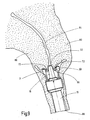
- FIG. 8 now shows a situation in which the device 10 is pushed through the vagina 88 and is brought up to the cervix 82 of a uterus 80.
- a rinsing liquid can be carried out.
- an endoscope may be passed to perform visual observations in the cervical canal 84.
- Instruments may also be performed to remove, for example, cysts or ulcers or the like in the cervical canal 84.
Applications Claiming Priority (1)
| Application Number | Priority Date | Filing Date | Title |
|---|---|---|---|
| DE102006016002A DE102006016002A1 (de) | 2006-03-30 | 2006-03-30 | Vorrichtung zum Durchführen von Untersuchungen und chirurgischen Eingriffen an der Gebärmutter |
Publications (2)
| Publication Number | Publication Date |
|---|---|
| EP1839604A1 true EP1839604A1 (fr) | 2007-10-03 |
| EP1839604B1 EP1839604B1 (fr) | 2012-10-03 |
Family
ID=38229126
Family Applications (1)
| Application Number | Title | Priority Date | Filing Date |
|---|---|---|---|
| EP07006115A Active EP1839604B1 (fr) | 2006-03-30 | 2007-03-24 | Dispositif destiné à l'exécution de recherches et opérations chirurgicales de l'utérus |
Country Status (3)
| Country | Link |
|---|---|
| US (1) | US8702723B2 (fr) |
| EP (1) | EP1839604B1 (fr) |
| DE (1) | DE102006016002A1 (fr) |
Cited By (5)
| Publication number | Priority date | Publication date | Assignee | Title |
|---|---|---|---|---|
| WO2013163609A1 (fr) * | 2012-04-26 | 2013-10-31 | Imds Corporation | Système de fixation de tissu pour saisir, retenir et libérer un tissu |
| CN105615961A (zh) * | 2014-08-04 | 2016-06-01 | 李峰 | 一种气管异物钳钳体 |
| CN109907806A (zh) * | 2019-04-26 | 2019-06-21 | 大连市妇女儿童医疗中心 | 举宫器 |
| CN111407381A (zh) * | 2020-04-09 | 2020-07-14 | 河北医科大学第四医院 | 一种自动举宫器 |
| CN111870327A (zh) * | 2020-09-04 | 2020-11-03 | 孙媛 | 一种妇产自动冲洗式刮宫装置 |
Families Citing this family (11)
| Publication number | Priority date | Publication date | Assignee | Title |
|---|---|---|---|---|
| DE102010024136B4 (de) * | 2010-06-17 | 2016-07-07 | Olympus Winter & Ibe Gmbh | Uterusmanipulator mit verstellbarer Portiokappe |
| US8608738B2 (en) | 2010-12-06 | 2013-12-17 | Soulor Surgical, Inc. | Apparatus for treating a portion of a reproductive system and related methods of use |
| US8603105B2 (en) * | 2011-06-21 | 2013-12-10 | Lsi Solutions, Inc. | Ergonomic, lighted uterine manipulator with cautery |
| US9089365B2 (en) | 2012-04-26 | 2015-07-28 | Imds Llc | Tissue fixation device |
| USD749725S1 (en) * | 2012-09-21 | 2016-02-16 | Lsi Solutions, Inc. | Handheld uterine manipulator with cervical cup |
| BR302014001463S1 (pt) * | 2013-10-04 | 2015-05-26 | Storz Karl Gmbh & Co Kg | Configuração aplicada em instrumento médico |
| US10092323B2 (en) | 2013-11-01 | 2018-10-09 | Lsi Solutions, Inc. | Ergonomic, lighted uterine manipulator with cautery |
| DE102015212379A1 (de) | 2015-07-02 | 2017-01-05 | Olympus Winter & Ibe Gmbh | Medizinisches Instrument, insbesondere Uterusmanipulator |
| US10806522B2 (en) | 2016-02-10 | 2020-10-20 | Covidien Lp | Colpotomy system for total laparoscopic hysterectomy |
| CN108420513B (zh) * | 2018-03-24 | 2024-05-03 | 王雷 | 子宫切除器 |
| US11730517B2 (en) | 2020-05-12 | 2023-08-22 | Covidien Lp | Robotic uterine manipulators with rollable sleeves |
Citations (4)
| Publication number | Priority date | Publication date | Assignee | Title |
|---|---|---|---|---|
| US5571115A (en) * | 1992-02-12 | 1996-11-05 | United States Surgical Corporation | Manipulator apparatus |
| DE19603981A1 (de) * | 1996-02-05 | 1997-08-07 | Wolf Gmbh Richard | Medizinisches Instrument zur Uterusmanipulation |
| DE20110921U1 (de) * | 2001-07-05 | 2001-12-06 | Trokamed Hengstler Gmbh | Uterus Manipulator |
| WO2002065924A2 (fr) * | 2001-02-20 | 2002-08-29 | Marcus Vincent Van Heerden | Manipulateur uterin |
Family Cites Families (7)
| Publication number | Priority date | Publication date | Assignee | Title |
|---|---|---|---|---|
| GB457229A (en) * | 1935-10-16 | 1936-11-24 | Herbert Linwood Sleigh | Improvements relating to the frames of vehicle and other seats |
| GB467229A (en) | 1935-12-05 | 1937-06-07 | George Arthur Marshall | New and useful improvements in the manufacture of obstetrical instruments for animaland human use |
| US3995619A (en) * | 1975-10-14 | 1976-12-07 | Glatzer Stephen G | Combination subcutaneous suture remover, biopsy sampler and syringe |
| JPS54144787A (en) * | 1978-05-02 | 1979-11-12 | Ouchi Teruo | Device for curving endoscope |
| US5709697A (en) * | 1995-11-22 | 1998-01-20 | United States Surgical Corporation | Apparatus and method for removing tissue |
| JPH11225951A (ja) * | 1998-02-17 | 1999-08-24 | Olympus Optical Co Ltd | 内視鏡用処置具 |
| US5980534A (en) * | 1998-10-07 | 1999-11-09 | Gimpelson; Richard J. | Cervical clamp |
-
2006
- 2006-03-30 DE DE102006016002A patent/DE102006016002A1/de not_active Withdrawn
-
2007
- 2007-03-24 EP EP07006115A patent/EP1839604B1/fr active Active
- 2007-03-30 US US11/694,026 patent/US8702723B2/en active Active
Patent Citations (4)
| Publication number | Priority date | Publication date | Assignee | Title |
|---|---|---|---|---|
| US5571115A (en) * | 1992-02-12 | 1996-11-05 | United States Surgical Corporation | Manipulator apparatus |
| DE19603981A1 (de) * | 1996-02-05 | 1997-08-07 | Wolf Gmbh Richard | Medizinisches Instrument zur Uterusmanipulation |
| WO2002065924A2 (fr) * | 2001-02-20 | 2002-08-29 | Marcus Vincent Van Heerden | Manipulateur uterin |
| DE20110921U1 (de) * | 2001-07-05 | 2001-12-06 | Trokamed Hengstler Gmbh | Uterus Manipulator |
Cited By (7)
| Publication number | Priority date | Publication date | Assignee | Title |
|---|---|---|---|---|
| WO2013163609A1 (fr) * | 2012-04-26 | 2013-10-31 | Imds Corporation | Système de fixation de tissu pour saisir, retenir et libérer un tissu |
| CN105615961A (zh) * | 2014-08-04 | 2016-06-01 | 李峰 | 一种气管异物钳钳体 |
| CN105615961B (zh) * | 2014-08-04 | 2017-12-22 | 张丛 | 一种气管异物钳钳体 |
| CN109907806A (zh) * | 2019-04-26 | 2019-06-21 | 大连市妇女儿童医疗中心 | 举宫器 |
| CN109907806B (zh) * | 2019-04-26 | 2021-04-02 | 大连市妇女儿童医疗中心 | 举宫器 |
| CN111407381A (zh) * | 2020-04-09 | 2020-07-14 | 河北医科大学第四医院 | 一种自动举宫器 |
| CN111870327A (zh) * | 2020-09-04 | 2020-11-03 | 孙媛 | 一种妇产自动冲洗式刮宫装置 |
Also Published As
| Publication number | Publication date |
|---|---|
| DE102006016002A1 (de) | 2007-10-04 |
| US8702723B2 (en) | 2014-04-22 |
| EP1839604B1 (fr) | 2012-10-03 |
| US20070260265A1 (en) | 2007-11-08 |
Similar Documents
| Publication | Publication Date | Title |
|---|---|---|
| EP1839604B1 (fr) | Dispositif destiné à l'exécution de recherches et opérations chirurgicales de l'utérus | |
| EP2060236B1 (fr) | Instrument médical destiné à la manipulation de l'utérus | |
| DE19912038C1 (de) | Handgriff für ein medizinisches Instrument | |
| DE19836481C1 (de) | Handgriff für ein medizinisches Instrument | |
| EP1056399B1 (fr) | Instrument a utiliser lors d'operations endoscopiques | |
| DE69735501T2 (de) | Systeme und instrumente zur minimal invasiven chirurgie | |
| EP0910293B1 (fr) | Instrument avec deux pinces independantes | |
| DE19652792C2 (de) | Medizinisches Handhabungsgerät, insbesondere für endoskopische Anwendungen | |
| DE19603981C2 (de) | Medizinisches Instrument zur Uterusmanipulation | |
| DE212019000498U1 (de) | Gleitschlitz-Mehrarmklemme | |
| EP0977513B1 (fr) | Instrument medical a tige coulissante | |
| DE102006042985A1 (de) | Elektrochirurgisches Instrument | |
| EP1750599B9 (fr) | Partie de prehension d'un instrument chirurgical | |
| EP1065979A1 (fr) | Instrument chirurgical muni d'un canal creux continu pour un autre instrument | |
| EP2769682B1 (fr) | Instrument endoscopique et tige pour un instrument endoscopique | |
| EP0926994B1 (fr) | Pince chirurgicale de prehension et de maintien | |
| DE102012110260B4 (de) | Betätigungsgriff für ein mikrochirurgisches Instrument | |
| EP1329201B1 (fr) | Instrument medical pour la chirurgie à caractère invasif minimum à assistance manuelle | |
| WO2018233773A1 (fr) | Instrument médical | |
| EP4346627A1 (fr) | Dispositif chirurgical permettant un maintien dans un tissu | |
| DE4216874C1 (fr) | ||
| DE102017114838A1 (de) | Getriebeanordnung und chirurgisches Instrument mit einer Getriebeanordnung | |
| DE102007001749B4 (de) | Chirurigsches Instrument | |
| DE102009037822B4 (de) | Medizinisches Instrument mit einer Haltesicherung | |
| DE212015000051U1 (de) | Chirurgischer Nadelhalter |
Legal Events
| Date | Code | Title | Description |
|---|---|---|---|
| PUAI | Public reference made under article 153(3) epc to a published international application that has entered the european phase |
Free format text: ORIGINAL CODE: 0009012 |
|
| AK | Designated contracting states |
Kind code of ref document: A1 Designated state(s): AT BE BG CH CY CZ DE DK EE ES FI FR GB GR HU IE IS IT LI LT LU LV MC MT NL PL PT RO SE SI SK TR |
|
| AX | Request for extension of the european patent |
Extension state: AL BA HR MK YU |
|
| 17P | Request for examination filed |
Effective date: 20080301 |
|
| AKX | Designation fees paid |
Designated state(s): DE FR GB IT |
|
| 17Q | First examination report despatched |
Effective date: 20100324 |
|
| GRAP | Despatch of communication of intention to grant a patent |
Free format text: ORIGINAL CODE: EPIDOSNIGR1 |
|
| GRAS | Grant fee paid |
Free format text: ORIGINAL CODE: EPIDOSNIGR3 |
|
| GRAA | (expected) grant |
Free format text: ORIGINAL CODE: 0009210 |
|
| AK | Designated contracting states |
Kind code of ref document: B1 Designated state(s): DE FR GB IT |
|
| REG | Reference to a national code |
Ref country code: GB Ref legal event code: FG4D Free format text: NOT ENGLISH |
|
| REG | Reference to a national code |
Ref country code: DE Ref legal event code: R081 Ref document number: 502007010611 Country of ref document: DE Owner name: KARL STORZ SE & CO. KG, DE Free format text: FORMER OWNER: KARL STORZ GMBH & CO. KG, 78532 TUTTLINGEN, DE |
|
| REG | Reference to a national code |
Ref country code: DE Ref legal event code: R096 Ref document number: 502007010611 Country of ref document: DE Effective date: 20121206 |
|
| PLBE | No opposition filed within time limit |
Free format text: ORIGINAL CODE: 0009261 |
|
| STAA | Information on the status of an ep patent application or granted ep patent |
Free format text: STATUS: NO OPPOSITION FILED WITHIN TIME LIMIT |
|
| 26N | No opposition filed |
Effective date: 20130704 |
|
| REG | Reference to a national code |
Ref country code: DE Ref legal event code: R097 Ref document number: 502007010611 Country of ref document: DE Effective date: 20130704 |
|
| REG | Reference to a national code |
Ref country code: FR Ref legal event code: PLFP Year of fee payment: 10 |
|
| REG | Reference to a national code |
Ref country code: FR Ref legal event code: PLFP Year of fee payment: 11 |
|
| REG | Reference to a national code |
Ref country code: DE Ref legal event code: R081 Ref document number: 502007010611 Country of ref document: DE Owner name: KARL STORZ SE & CO. KG INTELLECTUAL PROPERTY, DE Free format text: FORMER OWNER: KARL STORZ GMBH & CO. KG, 78532 TUTTLINGEN, DE Ref country code: DE Ref legal event code: R082 Ref document number: 502007010611 Country of ref document: DE Representative=s name: WITTE, WELLER & PARTNER PATENTANWAELTE MBB, DE Ref country code: DE Ref legal event code: R081 Ref document number: 502007010611 Country of ref document: DE Owner name: KARL STORZ SE & CO. KG, DE Free format text: FORMER OWNER: KARL STORZ GMBH & CO. KG, 78532 TUTTLINGEN, DE |
|
| REG | Reference to a national code |
Ref country code: FR Ref legal event code: PLFP Year of fee payment: 12 |
|
| PGFP | Annual fee paid to national office [announced via postgrant information from national office to epo] |
Ref country code: IT Payment date: 20180219 Year of fee payment: 12 |
|
| PG25 | Lapsed in a contracting state [announced via postgrant information from national office to epo] |
Ref country code: IT Free format text: LAPSE BECAUSE OF NON-PAYMENT OF DUE FEES Effective date: 20190324 |
|
| PGFP | Annual fee paid to national office [announced via postgrant information from national office to epo] |
Ref country code: FR Payment date: 20210218 Year of fee payment: 15 |
|
| PGFP | Annual fee paid to national office [announced via postgrant information from national office to epo] |
Ref country code: GB Payment date: 20210219 Year of fee payment: 15 |
|
| GBPC | Gb: european patent ceased through non-payment of renewal fee |
Effective date: 20220324 |
|
| PG25 | Lapsed in a contracting state [announced via postgrant information from national office to epo] |
Ref country code: GB Free format text: LAPSE BECAUSE OF NON-PAYMENT OF DUE FEES Effective date: 20220324 Ref country code: FR Free format text: LAPSE BECAUSE OF NON-PAYMENT OF DUE FEES Effective date: 20220331 |
|
| P01 | Opt-out of the competence of the unified patent court (upc) registered |
Effective date: 20230527 |
|
| PGFP | Annual fee paid to national office [announced via postgrant information from national office to epo] |
Ref country code: DE Payment date: 20240328 Year of fee payment: 18 |