EP1838244B1 - Lentille intraoculaire mince - Google Patents
Lentille intraoculaire mince Download PDFInfo
- Publication number
- EP1838244B1 EP1838244B1 EP05808164.7A EP05808164A EP1838244B1 EP 1838244 B1 EP1838244 B1 EP 1838244B1 EP 05808164 A EP05808164 A EP 05808164A EP 1838244 B1 EP1838244 B1 EP 1838244B1
- Authority
- EP
- European Patent Office
- Prior art keywords
- iol
- haptic
- haptics
- optic
- thickness
- Prior art date
- Legal status (The legal status is an assumption and is not a legal conclusion. Google has not performed a legal analysis and makes no representation as to the accuracy of the status listed.)
- Active
Links
- 230000007423 decrease Effects 0.000 claims description 30
- 230000003287 optical effect Effects 0.000 claims description 12
- 239000000463 material Substances 0.000 claims description 5
- NIXOWILDQLNWCW-UHFFFAOYSA-N acrylic acid group Chemical group C(C=C)(=O)O NIXOWILDQLNWCW-UHFFFAOYSA-N 0.000 claims description 2
- 238000001356 surgical procedure Methods 0.000 description 8
- 230000033001 locomotion Effects 0.000 description 6
- 208000002177 Cataract Diseases 0.000 description 4
- 210000001525 retina Anatomy 0.000 description 4
- 210000004087 cornea Anatomy 0.000 description 3
- 238000013461 design Methods 0.000 description 3
- 239000013598 vector Substances 0.000 description 3
- 230000004888 barrier function Effects 0.000 description 2
- 230000003247 decreasing effect Effects 0.000 description 2
- 230000010393 epithelial cell migration Effects 0.000 description 2
- 210000002159 anterior chamber Anatomy 0.000 description 1
- 201000009310 astigmatism Diseases 0.000 description 1
- 230000015572 biosynthetic process Effects 0.000 description 1
- 230000001413 cellular effect Effects 0.000 description 1
- 230000006835 compression Effects 0.000 description 1
- 238000007906 compression Methods 0.000 description 1
- 238000010276 construction Methods 0.000 description 1
- 230000001419 dependent effect Effects 0.000 description 1
- 238000000605 extraction Methods 0.000 description 1
- 238000010438 heat treatment Methods 0.000 description 1
- 238000002513 implantation Methods 0.000 description 1
- 238000003780 insertion Methods 0.000 description 1
- 230000037431 insertion Effects 0.000 description 1
- 238000005259 measurement Methods 0.000 description 1
- 230000005012 migration Effects 0.000 description 1
- 238000013508 migration Methods 0.000 description 1
- 230000002093 peripheral effect Effects 0.000 description 1
- 229920001296 polysiloxane Polymers 0.000 description 1
- 230000002250 progressing effect Effects 0.000 description 1
Images


Classifications
-
- A—HUMAN NECESSITIES
- A61—MEDICAL OR VETERINARY SCIENCE; HYGIENE
- A61F—FILTERS IMPLANTABLE INTO BLOOD VESSELS; PROSTHESES; DEVICES PROVIDING PATENCY TO, OR PREVENTING COLLAPSING OF, TUBULAR STRUCTURES OF THE BODY, e.g. STENTS; ORTHOPAEDIC, NURSING OR CONTRACEPTIVE DEVICES; FOMENTATION; TREATMENT OR PROTECTION OF EYES OR EARS; BANDAGES, DRESSINGS OR ABSORBENT PADS; FIRST-AID KITS
- A61F2/00—Filters implantable into blood vessels; Prostheses, i.e. artificial substitutes or replacements for parts of the body; Appliances for connecting them with the body; Devices providing patency to, or preventing collapsing of, tubular structures of the body, e.g. stents
- A61F2/02—Prostheses implantable into the body
- A61F2/14—Eye parts, e.g. lenses, corneal implants; Implanting instruments specially adapted therefor; Artificial eyes
- A61F2/16—Intraocular lenses
- A61F2/1613—Intraocular lenses having special lens configurations, e.g. multipart lenses; having particular optical properties, e.g. pseudo-accommodative lenses, lenses having aberration corrections, diffractive lenses, lenses for variably absorbing electromagnetic radiation, lenses having variable focus
- A61F2/1616—Pseudo-accommodative, e.g. multifocal or enabling monovision
-
- A—HUMAN NECESSITIES
- A61—MEDICAL OR VETERINARY SCIENCE; HYGIENE
- A61F—FILTERS IMPLANTABLE INTO BLOOD VESSELS; PROSTHESES; DEVICES PROVIDING PATENCY TO, OR PREVENTING COLLAPSING OF, TUBULAR STRUCTURES OF THE BODY, e.g. STENTS; ORTHOPAEDIC, NURSING OR CONTRACEPTIVE DEVICES; FOMENTATION; TREATMENT OR PROTECTION OF EYES OR EARS; BANDAGES, DRESSINGS OR ABSORBENT PADS; FIRST-AID KITS
- A61F2/00—Filters implantable into blood vessels; Prostheses, i.e. artificial substitutes or replacements for parts of the body; Appliances for connecting them with the body; Devices providing patency to, or preventing collapsing of, tubular structures of the body, e.g. stents
- A61F2/02—Prostheses implantable into the body
- A61F2/14—Eye parts, e.g. lenses, corneal implants; Implanting instruments specially adapted therefor; Artificial eyes
- A61F2/16—Intraocular lenses
- A61F2/1613—Intraocular lenses having special lens configurations, e.g. multipart lenses; having particular optical properties, e.g. pseudo-accommodative lenses, lenses having aberration corrections, diffractive lenses, lenses for variably absorbing electromagnetic radiation, lenses having variable focus
- A61F2/1648—Multipart lenses
-
- A—HUMAN NECESSITIES
- A61—MEDICAL OR VETERINARY SCIENCE; HYGIENE
- A61F—FILTERS IMPLANTABLE INTO BLOOD VESSELS; PROSTHESES; DEVICES PROVIDING PATENCY TO, OR PREVENTING COLLAPSING OF, TUBULAR STRUCTURES OF THE BODY, e.g. STENTS; ORTHOPAEDIC, NURSING OR CONTRACEPTIVE DEVICES; FOMENTATION; TREATMENT OR PROTECTION OF EYES OR EARS; BANDAGES, DRESSINGS OR ABSORBENT PADS; FIRST-AID KITS
- A61F2/00—Filters implantable into blood vessels; Prostheses, i.e. artificial substitutes or replacements for parts of the body; Appliances for connecting them with the body; Devices providing patency to, or preventing collapsing of, tubular structures of the body, e.g. stents
- A61F2/02—Prostheses implantable into the body
- A61F2/14—Eye parts, e.g. lenses, corneal implants; Implanting instruments specially adapted therefor; Artificial eyes
- A61F2/16—Intraocular lenses
- A61F2002/1681—Intraocular lenses having supporting structure for lens, e.g. haptics
- A61F2002/1689—Intraocular lenses having supporting structure for lens, e.g. haptics having plate-haptics
-
- A—HUMAN NECESSITIES
- A61—MEDICAL OR VETERINARY SCIENCE; HYGIENE
- A61F—FILTERS IMPLANTABLE INTO BLOOD VESSELS; PROSTHESES; DEVICES PROVIDING PATENCY TO, OR PREVENTING COLLAPSING OF, TUBULAR STRUCTURES OF THE BODY, e.g. STENTS; ORTHOPAEDIC, NURSING OR CONTRACEPTIVE DEVICES; FOMENTATION; TREATMENT OR PROTECTION OF EYES OR EARS; BANDAGES, DRESSINGS OR ABSORBENT PADS; FIRST-AID KITS
- A61F2250/00—Special features of prostheses classified in groups A61F2/00 - A61F2/26 or A61F2/82 or A61F9/00 or A61F11/00 or subgroups thereof
- A61F2250/0058—Additional features; Implant or prostheses properties not otherwise provided for
- A61F2250/0073—Force-limiting means
Definitions
- the present invention relates to intraocular lenses (also commonly referred to as IOLs), and more particularly relates to a thin IOLs that can be inserted through a very small incision in the eye and into the evacuated capsular bag of an eye.
- IOLs intraocular lenses
- the present invention relates to intraocular lenses (also commonly referred to as IOLs), and more particularly relates to a thin IOLs that can be inserted through a very small incision in the eye and into the evacuated capsular bag of an eye.
- Cataract surgery commonly involves removal of the eye's natural but clouded lens which is located in the capsular bag using a surgical technique known as phacoemulsification. It is desirable to have an incision in the eye as small as possible to improve heating and discourage formation of post-cataract astigmatism caused by the healed incision.
- the standard of today's incision size is 3mm or less. With even more recent surgical techniques, i.e. bi-manual phacoemulsification or laser-phaco, incisions of less than 2mm are possible. Of course if the IOL and/or the insertion instrument are larger than the incision size, the incision must be enlarged.
- IOL inserter In order to pass a flexible IOL through a small incision, it must be compressed to a smaller size and inserted in the eye using an instrument such as forceps or an IOL inserter. Examples of IOL inserters may be seen in commonly assigned U.S. Patent Nos. 5,944,725 and 6,336,932 . It will thus be appreciated that the material and dimensions of the IOL will dictate how small the IOL may be compressed without undergoing damage (i.e., larger dimensioned IOLs will not compress as small as a smaller sized IOL). Of course, the IOL cannot be so small as to lose its intended purpose of restoring the function of the eye's natural lens.
- haptics Positioning elements known as haptics are thus incorporated into the IOL design to help position and stabilize the optic in the capsular bag.
- US 6,425,917 B1 discloses a phakic IOL film frame which is a haptic system based on high modulus harder material shaped skeletal frame or plate haptic assembled with low modulus softer elastomeric hinged zones.
- the rigid frame or haptic in combination with the soft hinges will ensure that the lens is ideally situated in the anterior chamber angle of the eye.
- aspects of the present invention address the above stated need by providing a thin, foldable, IOL for placement in an evacuated capsular bag of an eye, the IOL comprising an optic having opposite anterior and posterior surfaces surrounded by a periphery.
- the IOL comprising an optic having opposite anterior and posterior surfaces surrounded by a periphery.
- four flexible haptics extend radially outwardly from the periphery, the haptics each having an elongated section and terminating in a free end.
- the first and second haptics are spaced from one another along a first portion of the optic edge and the third and fourth haptics are spaced from one another along a second portion of the optic edge winch is opposite the first portion of the optic edge.
- each haptic include at least two spaced fingers that extend in an anterior direction.
- the fingers flex and decrease the radius of curvature thereof in response to a radial compressive force applied thereto while the optic remains substantially aligned along the eye's optical axis.
- the fingers may also move toward one another to absorb the tangential forces imparted by the shrinking capsular bag.
- the fingers each have a length preferably about a quarter the length of the respective elongated sections.
- the proximal haptic length is thicker than a respective distal haptic length.
- the IOL further comprises a sharp edge defined along the optic periphery.
- the sharp edge presses against the posterior wall of the bag and acts as a barrier against cellular migration and posterior capsular opacification caused thereby.
- Embodiments of the invention are direct to a foldable IOL, comprising: a) an optic having a geometric center and a periphery, b) at least two haptics coupled to said optic, each having a proximal end and a distal end, each of said haptics having a thickness that decreases by at least 10% from the proximal end to the distal end.
- each of said haptics has a thickness that decreases from the proximal end to the distal end by 10% to 60%.
- each of said haptics has a thickness that decreases from the proximal end to the distal end by 15% to 40%.
- the decrease in thickness in each haptic is measured over a central 65% portion of each haptic.
- Each haptic may include at least one step.
- each haptic includes at least two steps.
- the thickness decreases smoothly over the length of the haptics.
- the thickness decreases linearly over the length of the haptics. The thickness may decrease monotonically over the length of the haptics.
- Some embodiments are directed to a foldable IOL, comprising a) an optic having a geometric center and a periphery, b) at least two flexible haptics coupled to the optic, each haptic having an anterior surface and a posterior surface, and a proximal end and a distal end, each haptic being concave on the anterior surface between the proximal end and distal end.
- at least one of the haptics has a single curvature between the proximal end and the distal end.
- at least one of the haptics has at least two curvatures between the proximal end and the distal end.
- At least one of the haptics has a curvature that varies continuously between the proximal end and the distal end. In some embodiments, for at least one of the haptics, the curvature of the anterior surface and the posterior surface is substantially the same.
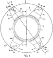
- IOL 10 includes an optic 11 having opposite anterior and posterior surfaces 12, 14, respectively, defining a geometric center GC and a periphery 16.
- the terms "anterior” and “posterior” refer to the anterior and posterior directions when IOL 10 is implanted in an eye.
- the anterior direction from the vantage point of the eye's capsular bag is toward the cornea.
- the posterior direction is toward the retina.
- the capsular bag 20 is schematically represented in Figs. 1 and 2 .
- Optic 11 is configured to direct light rays onto the eye's retina and thus replace the function of the eye's natural lens following removal thereof during cataract surgery.
- Optic 11 can be of any desired foldable material such as acrylic and silicone, for example, and the anterior and posterior surfaces 12, 14 may be of any desired optical design and combination thereof including planar, convex, concave, spherical and aspherical (including toric and multifocal).
- optic 11 is biconvex merely for purposes of discussion.
- the optic preferably has a maximum thickness T optic of between about 0.7 to 0.9mm.
- the IOL of the invention is intended for surgical implantation into the eye's capsular bag 20.
- the eye's natural lens is encased in a structure known as the capsular bag.
- the surgeon makes an opening (called a capsulorhexis) in the anterior wall 20c of the capsular bag 20 leaving an anterior wall flap 20d (see Fig. 2 ).
- the capsulorhexis is sized to be about 1mm less than the diameter of the IOL optic such that the anterior wall flap rests against the anterior surface of the IOL optic 11.
- the capsular bag 20 will shrink for about 3 months following surgery and this creates compressive forces on the implanted IOL.
- the IOL 10 is implanted such that the geometric center axis GC of optic 11 is substantially aligned along the eye's optical axis OA ( Fig. 2 ) and that this alignment be maintained in the presence of compressive forces being applied to the IOL.
- the present invention therefore provides an IOL designed to absorb these compressive forces while maintaining the optic geometric center GC substantially aligned along the optical axis OA. This is a particularly challenging endeavor when designing an IOL of thin construction.
- At least two haptics 30 extend from the optic periphery 16, the haptics being formed of a flexible material and configured to absorb compressive forces applied thereto.
- the haptics extend anteriorly at an angle "A" of about 5 to 15 degrees relative to the plane of the optic 11 (this angle is typically referred to as the vault angle).
- the terms "anterior”, “anteriorly” and “anterior direction” are meant to refer to the anterior direction (toward the cornea) when IOL 10 is implanted in an eye as described above.
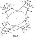
- IOL 10 includes four haptics 32-35 extending from optic periphery 16. Each haptic terminates in a free end 32a-35a which extends in an anterior direction relative to the elongated section 32b-35b of the respective haptic. With reference to Fig. 6 , in a preferred embodiment, haptic free ends 32a-35a extend relative to the elongated section of the respective haptic at an angle "B" of about 15° to 40° and more preferably about 33°. Each haptic free end 32a-35a may also taper from a maximum thickness T 3 to a minimum thickness T 4 . The tip of each haptic free end may be beveled with a bevel angle "C" of about 10° to 20° and more preferably about 18°.
- the elongated sections 32b-35b of haptics 32-35 When in an unstressed state (i.e., the state when no compressive forces are being applied to the IOL), the elongated sections 32b-35b of haptics 32-35 preferably extend substantially straight although a slight curvature is possible.
- the free ends 32a-35a each have a length preferably about a quarter of the length of the respective elongated sections 32b-35b although this may vary.
- the proximal haptic length (closer to periphery 16) has a thickness T 1 larger than the thickness T 2 of a respective distal haptic length (closer to the free end) (see Fig. 4 ).
- T 2 is between about 0.10 and 2.0mm and more preferably is about 0.15mm
- T 1 is between about 0.10 to 2.5mm and more preferably about 0.2mm.
- the thickness decreases by at least 10%. In some embodiments, the thickness decreases by at least 15%. In some embodiments, the thickness decreases by at least 20%.
- the reduction in thickness between the proximal end of the haptic and the distal end of the haptic is approximately in the range 10%-60%, and in some embodiments in the range 15%-40%, and in some embodiments in the range 20%-30%, and in some embodiments is approximately 25%.
- a thickness decrease is measured excluding any portion of the length of a haptic including a PCO sharp edge 13. Additionally, the thickness decrease is measured excluding any free end, thickness features, such free end features may include a localized increase in thickness to interface with the capsular bag. For example, in some embodiments, the reduction in thickness is measured over a central portion of approximately 65% of the length of the haptics (e.g., excluding the PCO sharp edge may exclude approximately 5%-15% of the distance along the proximal portion of the haptic, and excluding the free end may exclude approximately 20% of the distal portion of the haptic). Accordingly, it is to be appreciated that, a proximal end and/or a distal end may not be the absolute ends of the haptics.
- an IOL 10 illustrated in FIGs. 4 and 6 includes haptics having a single step in thickness
- haptics having two, three or four or more steps may also be implemented.
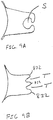
- the haptic illustrated in FIG. 7A includes two steps 136a and 136b forming three regions 137a, 137b and 137c having thickness of T 1 , T 2 and T 3 , respectively.
- each of the regions comprises a substantial portion of the length of the haptic (e.g., greater than approximately 15%, 20% or 30% of the haptic length).
- the regions may be equal in length.
- the regions may be approximately three equal regions comprising approximately 33% of the haptic length.
- the regions may be four equal regions of approximately 25%.
- the above haptics were discussed as having regions of equal length, it is to be appreciated that some embodiments have regions of substantial but unequal lengths on a haptic.
- at least one step 136c may be formed on an anterior surface of the haptic, and at least one step 136d formed on posterior surface of the haptic.
- the thickness is monotonically decreasing between the proximal end and the distal end. The term "monotonically decreasing" means that thickness does not increase when progressing from the proximal end to the distal end but may have one or more regions of constant thickness.
- the reduction in thickness decreases smoothly (i.e., there is no step) along the entire length or along one or more of the regions.
- the reduction in thickness is linear.
- the anterior and/or posterior side of the haptic may have a slope relative to a centerline 140 that extends along the length of the haptic and through the center of the thickness of the haptic.
- the reduction when proceeding from the proximal end to the distal end is greater than 15%; and in some embodiments the reduction in thickness is greater than 25%. It is to be appreciated that aspects of the invention directed to haptics having a reduced thickness as described in any of the embodiments described above may also have an angled free end, a haptic having a concave anterior surface, and/or fingers as described herein.
- the unstressed state of the exemplary embodiment of an IOL 10 is shown in solid lines.
- the optic 11 When implanted into the eye's capsular bag 20, the optic 11 is aligned substantially along the optical axis OA with the haptics 32-35 extending radially outward therefrom.
- the free ends 32a-35a of the haptics are positioned toward or near the bag equator 20b.
- radial compressive (stress) forces are applied to the IOL 10 and particularly along the haptics 32-35 thereof.
- the haptics 32-35 will flex with the direction of movement thereof being controlled by the free ends 32a-35a thereof.
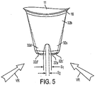
- the stressed state of the IOL 10 is shown in dashed lines in Figures 2 , 5 and 6 .
- the flexing movement proceeds in this predicted manner due to the unique haptic configurations of the invention.
- a compressive force is applied at the anteriorly extending free ends 32a-35a of the haptics, they respond by flexing further in an anterior direction. That is, they flex anteriorly and thereby decrease their radius of curvature from R 1 to R 2 where R 2 is less than R 1 ( Figs. 2 and 6 ).
- the haptics will flex anteriorly under a radial compressive force since the free ends 32a-35a already extend in an anterior direction (in their unstressed state as shown in solid lines) and are thus biased to continue flexing in this direction under compressive forces (to their stressed state as shown in dashed lines) as opposed to the opposite direction (i.e., posteriorly).
- the haptics will flex anteriorly under a radial compressive force since the proximal haptic length Hp (closer to periphery 16) has a thickness T 1 larger than the thickness T 2 of a respective distal haptic length H d (closer to the free end) as stated above. It is therefore practically an impossibility that the haptics would flex in the posterior direction under a radial compressive force.
- the anterior movement of the haptic flexing is initiated at the free ends 32a-35a thereof.
- the elongated sections 32b-35b of the haptics may also begin to flex anteriorly, predominantly at the thinner, distal haptic lengths DL thereof.
- the direction of haptic flex may also be considered with regard to the relation between the plane in which the haptics flex and the plane in which optic 11 lies. More particularly, the plane in which a respective haptic may flex is indicated at P h while the optic plane is indicated at P o in Figs. 1 and 2 . It is seen in these figures that these planes extend generally perpendicular to each other. It may thus be said that the haptics will flex in a respective plane P h that extends generally perpendicular to the plane P o in which optic 11 lies.
- optic 11 With the haptics thus absorbing the compressive forces in the manner described above, optic 11 remains substantially aligned along the eye's optical axis OA. When so aligned, the geometric center axis GC of the optic 11 is coincident with the eye's optical axis OA as shown in Fig. 2 . It is noted, however, that perfect alignment may not always be achievable due to variations in surgical techniques and capsular size, for example. Thus, while prefect alignment is the goal for best optical results, it is intended that the term "aligned" herein be interpreted to allow for less than perfect alignment between the geometric center of the optic and the eye's optical axis.
- optic 11 posterior movement of optic 11 is possible (along the optical axis OA), however, this is not considered a problem since firm contact between the posterior capsular wall 20a and the optic posterior surface 14 is desirable to prevent capsular opacification (PCO).
- optic 11 is provided with a sharp peripheral edge 13 which together with posterior capsular wall 20a, creates a barrier to epithelial cell migration from the capsular equator to the optic 11. Epithelial cell migration is a principal cause of PCO.
- the haptics may be curved along their lengths from the proximal end to the distal end, as illustrated in FIGs. 8A or 8B . That is, when traversing the haptic from the proximal end of the haptic to the distal end of the haptic, the lens is curved so as to be concave on the anterior surface of the haptic.
- the curvature has a single curvature along the entire length of the haptic from the proximal end to the distal end.
- the haptic may comprise two or more regions along the length, each region having a different curvature (not shown). In some embodiments, as illustrated in FIG.
- the haptic curvature varies continuously along the length of the haptic.
- the curvature or curvatures along the length of a haptic may be described, for example, by one or more of polynomial curvature, such as a conic curvature (e.g., an elliptical curvature, a hyperbolic curvature or a spherical curvature), a series of planar portions approximating a curve, or a curvature described point-by-point.
- the anterior surface and the posterior surface of the haptic have substantially the same curvatures as one another (the anterior surface being concave and the posterior surface being convex).
- the anterior surface and the posterior surface will have substantially the same curvature if the haptic has a uniform thickness along its length or if the thickness decreases a relatively small amount along its length.
- a curvature is determined excluding any portion of the length of a haptic including a PCO sharp edge 13. Additionally, the curvature of the haptic is determined excluding the free end features which may include a localized increase or decrease in curvature, for example, to interface with the capsular bag. For example, in some embodiments, the radius of curvature is measured over a central portion 820 approximately 65% of the haptics (e.g., excluding the PCO sharp edge 13 may exclude approximately 5%-15% of the distance along the haptic, and excluding free end 815 may exclude approximately 20% of the distal portion of the haptic).
- embodiments including a curvature as described above predispose a lens to move posteriorly upon radial compression resulting from shrinking of the capsular bag, and operates to maintain centration of the lens in a capsular bag. It is to be appreciated that aspects of the invention directed to a haptics having a curvature as described above may also have an angled free end, a reduced thickness, and/or fingers as described herein.
- the haptic free ends 32a-35a each comprise at least two spaced fingers 32c,d-35c,d, respectively ( Figs. 1 , 4 and 5 ).
- each finger pair extends substantially parallel to each other with the extreme tips 32c',d'-35c',d' thereof lying in a plane which is generally perpendicular to the geometric center axis GC of optic 11.
- the two fingers of a respective haptic may move toward one another to reduce or close the space therebetween such as from space S 1 to a space S 2 as shown in Fig. 5 .
- This movement absorbs particularly those compressive forces having a vector component directed tangentially to the circumference of the lens such as represented by vectors V R , for example, that are created by the dynamics of the shrinking capsular bag.
- the fingers are deformable toward one another in a tangential direction. It is to be appreciated the tangential force addressed by the fingers is perpendicular to the radial force addressed by the angle and curvature of the haptics discussed above.
- This aspect of the invention is particularly advantageous when combined with a thin lens design in that it also helps maintain the structural stability of the lens.
- This aspect is also advantageous when combined a structure capable of adapting to radial compressive forces such as a haptic having an anteriorly curved surface, a haptic that decreases in thickness from the proximal end to the distal end and/or haptics having angled free ends as described above. It is to be appreciated that, when used in such a combination, the lens is capable of maintaining stability in the presence of both tangential and radial forces which may result from capsular bag shrinkage.
- the groove may have any suitable shape.
- the IOL illustrated in Figure 9A includes a bulb-shaped notch S.
- the exemplary embodiment of an IOL illustrated in Figure 1 has two fingers, IOLs may have three, four, five or more fingers.
- the IOL illustrated in Figure 9B includes three fingers 832 and two notches T.
- the tips of the fingers 32c,d-35c,d extend at an angle of between about 10° and 50° relative to the remainder of the free end, and more preferably extends at an angle of between about 20° and 40°, and most preferably extends at an angle of about 33° relative to the remainder of a respective free end. It will be noticed that the angle corner may be located approximately mid-way along the space S 1 between each finger pair although this may vary.
- haptics are capable of absorbing compressive forces having a multitude of vectors such as those created by the dynamics of a shrinking capsular bag while the IOL optic 11 remains substantially aligned along the eye's optical axis as intended.
Landscapes
- Health & Medical Sciences (AREA)
- Ophthalmology & Optometry (AREA)
- Cardiology (AREA)
- Oral & Maxillofacial Surgery (AREA)
- Transplantation (AREA)
- Engineering & Computer Science (AREA)
- Biomedical Technology (AREA)
- Heart & Thoracic Surgery (AREA)
- Vascular Medicine (AREA)
- Life Sciences & Earth Sciences (AREA)
- Animal Behavior & Ethology (AREA)
- General Health & Medical Sciences (AREA)
- Public Health (AREA)
- Veterinary Medicine (AREA)
- Prostheses (AREA)
Claims (28)
- Lentille intraoculaire, IOL, pliable, pour le placement dans un sac capsulaire vidé d'un oeil, ladite IOL comprenant :(a) une optique (11) comportant des surfaces antérieure et postérieure opposées (12, 14) définissant un centre géométrique (GC) et une périphérie (16) ;(b) au moins deux haptiques (30, 32 à 35) ayant une section allongée (32b à 35b) et se terminant en une extrémité libre (32a à 35a), ladite extrémité libre (32a à 35a) s'étendant dans une direction antérieure selon un deuxième angle (B) par rapport à ladite section allongée (32b à 35b), caractérisée en ce que lesdites haptiques (30, 32 à 35) s'étendent chacune de ladite périphérie (16), chacune desdites haptiques (30, 32 à 35) a une épaisseur qui diminue de l'optique (11) jusqu'à l'extrémité libre (32a à 35a) ; lesdites haptiques (30, 32 à 35) s'étendent dans la direction antérieure selon un premier angle (A) par rapport à l'optique (11) ;dans laquelle, lorsqu'une force de compression radiale est appliquée aux extrémités libres (32a à 35a), les haptiques (30, 32 à 35) sont configurées pour fléchir dans la direction antérieure, et chacune des extrémités libres (32a à 35a) desdites haptiques (30, 32 à 35) est configurée pour fléchir dans un plan respectif qui s'étend généralement perpendiculairement au plan dans lequel l'optique (11) se trouve, dans laquelle l'optique (11) reste alignée le long de l'axe optique de l'oeil.
- IOL selon la revendication 1, dans laquelle ladite section allongée (32b à 35b) de chaque dite haptique (30, 32 à 35) s'étend sensiblement droite lorsqu'elle est dans une condition non contrainte.
- IOL selon la revendication 2, dans laquelle ledit deuxième angle (B) est entre environ 10° et 50°.
- IOL selon la revendication 2, dans laquelle ledit deuxième angle (B) est entre environ 20° et 40°.
- IOL selon la revendication 2, dans laquelle ledit deuxième angle (B) est d'environ 33°.
- IOL selon la revendication 2, dans laquelle l'épaisseur de chaque dite haptique (30, 32 à 35) diminue par pas.
- IOL selon la revendication 1, dans laquelle chaque extrémité libre (32a à 35a) comprend au moins deux doigts espacés (32c, d à 35c, d) se trouvant dans un plan commun qui s'étend généralement perpendiculairement à l'axe dudit centre géométrique optique (GC), lesdits au moins deux doigts espacés (32c, d à 35c, d) pouvant être déplacés les uns vers les autres en réponse à une force de compression appliquées à ceux-ci.
- IOL selon la revendication 7, dans laquelle chacune desdites extrémités libres (32a à 35a) comprend une extrémité chanfreinée.
- IOL selon la revendication 8, dans laquelle ladite extrémité chanfreinée a un angle de chanfrein (C) d'environ 10° à 20°.
- IOL selon la revendication 8, dans laquelle ladite extrémité chanfreinée a un angle de chanfrein (C) d'environ 18°.
- IOL selon la revendication 1, dans laquelle lesdites haptiques (30, 32 à 35) ont chacune une épaisseur maximum d'environ 0,2 mm.
- IOL selon la revendication 1, dans laquelle ladite lentille est réalisée en un matériau acrylique.
- IOL selon la revendication 1, dans laquelle chacune desdites extrémités libres (32a à 35a) comprend une extrémité chanfreinée.
- IOL selon la revendication 13, dans laquelle ladite extrémité chanfreinée a un angle de chanfrein (C) d'environ 10° à 20°.
- IOL selon la revendication 13, dans laquelle ladite extrémité chanfreinée a un angle de chanfrein (C) d'environ 18°.
- IOL selon la revendication 1, dans laquelle :l'épaisseur de chaque haptique (30, 32 à 35) diminue d'au moins 10 % de l'optique (11) jusqu'à l'extrémité libre (32a à 35a).
- IOL selon la revendication 16, dans laquelle l'épaisseur de chaque haptique (30, 32 à 35) diminue de 10 % à 60 % de l'optique (11) jusqu'à l'extrémité libre (32a à 35a).
- IOL selon la revendication 16, dans laquelle l'épaisseur de chaque haptique (30, 32 à 35) diminue de 15 % à 40 % de l'optique (11) jusqu'à l'extrémité libre (32a à 35a).
- IOL selon la revendication 16, dans laquelle l'épaisseur de chaque haptique (30, 32 à 35) diminue de 20 % à 30 % de l'optique (11) jusqu'à l'extrémité libre (32a à 35a).
- IOL selon la revendication 16, dans laquelle l'épaisseur de chaque haptique (30, 32 à 35) diminue d'environ 25 % de l'optique (11) jusqu'à l'extrémité libre (32a à 35a).
- IOL selon l'une quelconque des revendications 16 à 20, dans laquelle la diminution de l'épaisseur de chaque haptique (30, 32 à 35) se produit sur une partie centrale de 65 % de chaque haptique (30, 32 à 35).
- IOL selon l'une quelconque des revendications 16 à 20, dans laquelle chaque haptique (30, 32 à 35) comprend au moins un gradin.
- IOL selon l'une quelconque des revendications 16 à 20, dans laquelle chaque haptique (30, 32 à 35) comprend au moins deux gradins.
- IOL selon la revendication 23, dans laquelle au moins l'un des gradins est formé sur une surface antérieure d'au moins l'une des haptiques (30, 32 à 35) et au moins l'un des gradins est formé sur une surface postérieure d'au moins l'une des haptiques (30, 32 à 35).
- IOL selon l'une quelconque des revendications 16 à 20, dans laquelle l'épaisseur diminue régulièrement sur la longueur des haptiques (30, 32 à 35).
- IOL selon l'une quelconque des revendications 16 à 20, dans laquelle l'épaisseur diminue linéairement sur la longueur des haptiques (30, 32 à 35).
- IOL selon les revendications 16 à 20, dans laquelle l'épaisseur diminue de manière monotone sur la longueur des haptiques (30, 32 à 35).
- IOL selon la revendication 16, dans laquelle chaque haptique (30, 32 à 35) a une extrémité libre (32a à 35a) comprenant au moins deux doigts (32c, d à 35c, d) espacés l'un de l'autre.
Priority Applications (1)
| Application Number | Priority Date | Filing Date | Title |
|---|---|---|---|
| PL05808164T PL1838244T3 (pl) | 2004-11-19 | 2005-11-18 | Cienka soczewka wewnątrzgałkowa (lOL) |
Applications Claiming Priority (2)
| Application Number | Priority Date | Filing Date | Title |
|---|---|---|---|
| PCT/IB2004/004106 WO2006054130A1 (fr) | 2004-11-19 | 2004-11-19 | Cristallin artificiel mince |
| PCT/IB2005/003676 WO2006054178A2 (fr) | 2004-11-19 | 2005-11-18 | Implant intraoculaire mince |
Publications (2)
| Publication Number | Publication Date |
|---|---|
| EP1838244A2 EP1838244A2 (fr) | 2007-10-03 |
| EP1838244B1 true EP1838244B1 (fr) | 2017-06-07 |
Family
ID=34959604
Family Applications (1)
| Application Number | Title | Priority Date | Filing Date |
|---|---|---|---|
| EP05808164.7A Active EP1838244B1 (fr) | 2004-11-19 | 2005-11-18 | Lentille intraoculaire mince |
Country Status (10)
| Country | Link |
|---|---|
| US (1) | US9237946B2 (fr) |
| EP (1) | EP1838244B1 (fr) |
| JP (1) | JP5436780B2 (fr) |
| KR (1) | KR101304044B1 (fr) |
| CN (2) | CN101856281B (fr) |
| AU (1) | AU2005305605B2 (fr) |
| CA (2) | CA2588962C (fr) |
| ES (1) | ES2628589T3 (fr) |
| PL (1) | PL1838244T3 (fr) |
| WO (2) | WO2006054130A1 (fr) |
Families Citing this family (20)
| Publication number | Priority date | Publication date | Assignee | Title |
|---|---|---|---|---|
| US20080086208A1 (en) * | 2004-08-24 | 2008-04-10 | Nordan T Lee | Foldable Intraocular Lens With Adaptable Haptics |
| FR2922096B1 (fr) * | 2007-10-16 | 2010-01-08 | Ioltechnologie Production | Lentille intraoculaire pour sac capsulaire |
| US8940045B2 (en) * | 2010-11-24 | 2015-01-27 | Santen Pharmaceutical Co., Ltd. | Intraocular lens |
| JP6023799B2 (ja) * | 2011-05-23 | 2016-11-09 | カリフォルニア インスティチュート オブ テクノロジー | 調節性眼内レンズ |
| DE102012016893A1 (de) * | 2012-08-24 | 2014-05-15 | Be Innovative Gmbh | Intraokularlinse, insbesondere Kapselsackintraokularlinse |
| US10667903B2 (en) | 2013-01-15 | 2020-06-02 | Medicem Institute s.r.o. | Bioanalogic intraocular lens |
| US10441676B2 (en) | 2013-01-15 | 2019-10-15 | Medicem Institute s.r.o. | Light-adjustable hydrogel and bioanalogic intraocular lens |
| US11109957B2 (en) | 2014-09-22 | 2021-09-07 | Onpoint Vision, Inc. | Intraocular pseudophakic contact lens with mechanism for securing by anterior leaflet of capsular wall and related system and method |
| US10945832B2 (en) | 2014-09-22 | 2021-03-16 | Onpoint Vision, Inc. | Intraocular pseudophakic contact lens with mechanism for securing by anterior leaflet of capsular wall and related system and method |
| US11938018B2 (en) | 2014-09-22 | 2024-03-26 | Onpoint Vision, Inc. | Intraocular pseudophakic contact lens (IOPCL) for treating age-related macular degeneration (AMD) or other eye disorders |
| US10299910B2 (en) | 2014-09-22 | 2019-05-28 | Kevin J. Cady | Intraocular pseudophakic contact lens with mechanism for securing by anterior leaflet of capsular wall and related system and method |
| US10159562B2 (en) | 2014-09-22 | 2018-12-25 | Kevin J. Cady | Intraocular pseudophakic contact lenses and related systems and methods |
| JP6564031B2 (ja) | 2014-12-09 | 2019-08-21 | ノバルティス アーゲー | 調節性曲率変化眼内レンズ |
| WO2016160178A1 (fr) * | 2015-04-02 | 2016-10-06 | Novartis Ag | Lentille intraoculaire de type plaque, stable, facilitant une taille d'incision réduite |
| US11696823B2 (en) | 2015-04-14 | 2023-07-11 | Z Optics, Inc. | High definition and extended depth of field intraocular lens |
| US10285807B2 (en) * | 2015-04-14 | 2019-05-14 | Z Optics LLC | High definition and extended depth of field intraocular lens |
| US11547554B2 (en) | 2015-04-14 | 2023-01-10 | Z Optics, Inc. | High definition and extended depth of field intraocular lens |
| WO2020083828A1 (fr) * | 2018-10-24 | 2020-04-30 | Amo Groningen B.V. | Lentilles intraoculaires destinées à réduire le risque d'opacification de la capsule postérieure |
| GB2578639A (en) * | 2018-11-02 | 2020-05-20 | Rayner Intraocular Lenses Ltd | Hybrid accommodating intraocular lens assemblages including discrete lens unit with segmented lens haptics |
| KR102579838B1 (ko) * | 2021-03-11 | 2023-09-26 | 김주영 | 난시를 교정하기 위한 인공수정체 |
Family Cites Families (44)
| Publication number | Priority date | Publication date | Assignee | Title |
|---|---|---|---|---|
| DE2607462C3 (de) * | 1976-02-24 | 1982-11-04 | INPROHOLD Establishment, 9490 Vaduz | Linse als Ersatz für die aus dem Auge von Lebewesen operativ entfernte natürliche Linse |
| US4134160A (en) * | 1977-03-16 | 1979-01-16 | Bayers Jon Herbert | Intraocular lens |
| US4087866A (en) * | 1977-04-26 | 1978-05-09 | Coburn Optical Industries, Inc. | Intraocular lens |
| US4261065A (en) * | 1979-07-27 | 1981-04-14 | Tennant Jerald L | Artificial intraocular lens with forward-positioned optics |
| US4872876A (en) * | 1988-05-11 | 1989-10-10 | Nestle S.A. | Universal fit intraocular lens |
| US5476514A (en) * | 1990-04-27 | 1995-12-19 | Cumming; J. Stuart | Accommodating intraocular lens |
| US6197059B1 (en) * | 1990-04-27 | 2001-03-06 | Medevec Licensing, B.V. | Accomodating intraocular lens |
| US5217491A (en) * | 1990-12-27 | 1993-06-08 | American Cyanamid Company | Composite intraocular lens |
| US5476513A (en) * | 1992-02-28 | 1995-12-19 | Allergan, Inc. | Intraocular lens |
| US6322589B1 (en) * | 1995-10-06 | 2001-11-27 | J. Stuart Cumming | Intraocular lenses with fixated haptics |
| ES2207652T3 (es) * | 1994-08-05 | 2004-06-01 | BAUSCH & LOMB INCORPORATED | Dispositivo para la insercion de una lente intraocular flexible. |
| FR2723691B1 (fr) * | 1994-08-22 | 1997-01-24 | Philippe Crozafon | Implant intra-oculaire |
| JPH0876067A (ja) | 1994-09-09 | 1996-03-22 | Menicon Co Ltd | 眼内レンズ及びその製造方法 |
| ATE394080T1 (de) * | 1995-02-15 | 2008-05-15 | Medevec Licensing Bv | Anpassbare intraokulare linse mit t-förmigen haltebügeln |
| WO1997012564A1 (fr) * | 1995-10-06 | 1997-04-10 | Cumming J Stuart | Lentilles intraoculaires a haptiques fixes |
| US5944725A (en) * | 1996-09-26 | 1999-08-31 | Bausch & Lomb Surgical, Inc. | Method and apparatus for inserting a flexible membrane into an eye |
| US20050107875A1 (en) * | 1997-05-20 | 2005-05-19 | Eyeonics, Inc. | Accommodating lens with haptics |
| US5928282A (en) * | 1997-06-13 | 1999-07-27 | Bausch & Lomb Surgical, Inc. | Intraocular lens |
| US6162249A (en) * | 1998-05-29 | 2000-12-19 | Allergan | IOI for inhibiting cell growth and reducing glare |
| US6228115B1 (en) * | 1998-11-05 | 2001-05-08 | Bausch & Lomb Surgical, Inc. | Intraocular lenses with improved axial stability |
| US6224628B1 (en) * | 1999-04-23 | 2001-05-01 | Thinoptx, Inc. | Haptics for an intraocular lens |
| US6200344B1 (en) * | 1999-04-29 | 2001-03-13 | Bausch & Lomb Surgical, Inc. | Inraocular lenses |
| US6406494B1 (en) * | 1999-04-30 | 2002-06-18 | Allergan Sales, Inc. | Moveable intraocular lens |
| FR2795944B1 (fr) * | 1999-07-08 | 2001-11-02 | Corneal Ind | Implant intraoculaire |
| US6685741B2 (en) * | 1999-07-29 | 2004-02-03 | Bausch & Lomb Incorporated | Intraocular lenses |
| US20020087210A1 (en) * | 1999-09-02 | 2002-07-04 | Donald Carrol Stenger | Intraocular |
| FR2804860B1 (fr) * | 2000-02-16 | 2002-04-12 | Humanoptics Ag | Implant cristallinien accomodatif |
| US6425917B1 (en) * | 2000-05-12 | 2002-07-30 | Tekia | Phakic iol film frame |
| US6554860B2 (en) * | 2000-05-15 | 2003-04-29 | Bausch & Lomb Incorporated | Foldable iris fixated intraocular lenses |
| US6849091B1 (en) * | 2000-05-19 | 2005-02-01 | Eyeonics, Inc. | Lens assembly for depth of focus |
| US6827738B2 (en) * | 2001-01-30 | 2004-12-07 | Timothy R. Willis | Refractive intraocular implant lens and method |
| US20030014107A1 (en) * | 2001-06-28 | 2003-01-16 | Michael Reynard | Multifocal phakic intraocular lens |
| JP4054551B2 (ja) * | 2001-07-11 | 2008-02-27 | 株式会社ニデック | 眼内レンズ研磨方法 |
| DE10139027A1 (de) * | 2001-08-15 | 2003-02-27 | Humanoptics Ag | Intraokulares Implantat |
| US20030097177A1 (en) * | 2001-11-21 | 2003-05-22 | Tran Son Trung | Posterior chamber phakic lens |
| US20050107874A1 (en) | 2002-03-18 | 2005-05-19 | Ehud Assia | Sharp angle intraocular lens optic |
| US20030187505A1 (en) * | 2002-03-29 | 2003-10-02 | Xiugao Liao | Accommodating intraocular lens with textured haptics |
| US20030204257A1 (en) | 2002-04-29 | 2003-10-30 | Southard Michael A. | Intraocular lens |
| US20040059414A1 (en) | 2002-09-25 | 2004-03-25 | Green George F. | Intraocular lens |
| FR2858544B1 (fr) | 2003-08-04 | 2006-04-28 | Corneal Ind | Implant intraoculaire souple de faible epaisseur |
| US20070027539A1 (en) | 2003-09-30 | 2007-02-01 | Joel Pynson | Intaocular lens for inhibiting pco and aco |
| US20050187621A1 (en) * | 2004-02-24 | 2005-08-25 | Brady Daniel G. | Foldable unitary intraocular lens |
| DE102004021755A1 (de) * | 2004-04-30 | 2005-11-17 | Humanoptics Ag | Intraokularlinse |
| US7063723B2 (en) * | 2004-07-23 | 2006-06-20 | Sun Ran | Intraocular lens with an accommodating capability |
-
2004
- 2004-11-19 WO PCT/IB2004/004106 patent/WO2006054130A1/fr active Application Filing
-
2005
- 2005-11-18 CA CA2588962A patent/CA2588962C/fr active Active
- 2005-11-18 ES ES05808164.7T patent/ES2628589T3/es active Active
- 2005-11-18 AU AU2005305605A patent/AU2005305605B2/en active Active
- 2005-11-18 CA CA2718020A patent/CA2718020C/fr active Active
- 2005-11-18 WO PCT/IB2005/003676 patent/WO2006054178A2/fr active Application Filing
- 2005-11-18 CN CN201010227015.3A patent/CN101856281B/zh active Active
- 2005-11-18 KR KR1020077013719A patent/KR101304044B1/ko active IP Right Grant
- 2005-11-18 CN CN2005800463411A patent/CN101098665B/zh active Active
- 2005-11-18 JP JP2007542361A patent/JP5436780B2/ja active Active
- 2005-11-18 PL PL05808164T patent/PL1838244T3/pl unknown
- 2005-11-18 EP EP05808164.7A patent/EP1838244B1/fr active Active
- 2005-11-18 US US11/719,471 patent/US9237946B2/en active Active
Non-Patent Citations (1)
| Title |
|---|
| None * |
Also Published As
| Publication number | Publication date |
|---|---|
| KR101304044B1 (ko) | 2013-09-04 |
| JP5436780B2 (ja) | 2014-03-05 |
| ES2628589T3 (es) | 2017-08-03 |
| CN101856281A (zh) | 2010-10-13 |
| CA2588962C (fr) | 2011-01-04 |
| CN101098665A (zh) | 2008-01-02 |
| AU2005305605B2 (en) | 2012-01-12 |
| US9237946B2 (en) | 2016-01-19 |
| PL1838244T3 (pl) | 2017-10-31 |
| CA2718020A1 (fr) | 2006-05-26 |
| CN101098665B (zh) | 2010-09-15 |
| AU2005305605A1 (en) | 2006-05-26 |
| KR20070086348A (ko) | 2007-08-27 |
| WO2006054130A1 (fr) | 2006-05-26 |
| CN101856281B (zh) | 2015-01-28 |
| WO2006054178A3 (fr) | 2006-09-28 |
| EP1838244A2 (fr) | 2007-10-03 |
| JP2008520310A (ja) | 2008-06-19 |
| CA2588962A1 (fr) | 2006-05-26 |
| US20090228102A1 (en) | 2009-09-10 |
| CA2718020C (fr) | 2013-10-29 |
| WO2006054178A2 (fr) | 2006-05-26 |
Similar Documents
| Publication | Publication Date | Title |
|---|---|---|
| EP1838244B1 (fr) | Lentille intraoculaire mince | |
| US8100965B2 (en) | Floating optic accommodating intraocular lens | |
| US7985253B2 (en) | Hydrolic accommodating intraocular lens | |
| US8163015B2 (en) | “W” accommodating intraocular lens | |
| US20080154362A1 (en) | "w" accommodating intraocular lens with elastic hinges | |
| US6533814B1 (en) | Intraocular lens having a design for controlling its axial displacement after implantation | |
| US20080027539A1 (en) | "W" Accommodating Intraocular Lens | |
| US6616693B1 (en) | Flexible fixation members for angle-supported anterior chamber intraocular lenses | |
| US20040034417A1 (en) | Intraocular lens | |
| US11284992B2 (en) | Intraocular lens platform having improved haptic force distribution | |
| US20030018386A1 (en) | Anterior chamber angle-supported intraocular lenses with flexible optic and rigid fixation members | |
| JP7518266B2 (ja) | 閉ループ支持部構造体を有する眼内レンズ | |
| US20220218467A1 (en) | Variable thickness dynamic membrane for accommodating intraocular lenses | |
| WO2020236619A1 (fr) | Lentille intraoculaire améliorée |
Legal Events
| Date | Code | Title | Description |
|---|---|---|---|
| PUAI | Public reference made under article 153(3) epc to a published international application that has entered the european phase |
Free format text: ORIGINAL CODE: 0009012 |
|
| 17P | Request for examination filed |
Effective date: 20070618 |
|
| AK | Designated contracting states |
Kind code of ref document: A2 Designated state(s): AT BE BG CH CY CZ DE DK EE ES FI FR GB GR HU IE IS IT LI LT LU LV MC NL PL PT RO SE SI SK TR |
|
| REG | Reference to a national code |
Ref country code: HK Ref legal event code: DE Ref document number: 1103617 Country of ref document: HK |
|
| DAX | Request for extension of the european patent (deleted) | ||
| 17Q | First examination report despatched |
Effective date: 20150910 |
|
| GRAP | Despatch of communication of intention to grant a patent |
Free format text: ORIGINAL CODE: EPIDOSNIGR1 |
|
| STAA | Information on the status of an ep patent application or granted ep patent |
Free format text: STATUS: GRANT OF PATENT IS INTENDED |
|
| RAP1 | Party data changed (applicant data changed or rights of an application transferred) |
Owner name: BAUSCH & LOMB INCORPORATED |
|
| INTG | Intention to grant announced |
Effective date: 20161102 |
|
| GRAS | Grant fee paid |
Free format text: ORIGINAL CODE: EPIDOSNIGR3 |
|
| GRAJ | Information related to disapproval of communication of intention to grant by the applicant or resumption of examination proceedings by the epo deleted |
Free format text: ORIGINAL CODE: EPIDOSDIGR1 |
|
| GRAL | Information related to payment of fee for publishing/printing deleted |
Free format text: ORIGINAL CODE: EPIDOSDIGR3 |
|
| STAA | Information on the status of an ep patent application or granted ep patent |
Free format text: STATUS: EXAMINATION IS IN PROGRESS |
|
| INTC | Intention to grant announced (deleted) | ||
| GRAR | Information related to intention to grant a patent recorded |
Free format text: ORIGINAL CODE: EPIDOSNIGR71 |
|
| STAA | Information on the status of an ep patent application or granted ep patent |
Free format text: STATUS: GRANT OF PATENT IS INTENDED |
|
| GRAA | (expected) grant |
Free format text: ORIGINAL CODE: 0009210 |
|
| STAA | Information on the status of an ep patent application or granted ep patent |
Free format text: STATUS: THE PATENT HAS BEEN GRANTED |
|
| AK | Designated contracting states |
Kind code of ref document: B1 Designated state(s): AT BE BG CH CY CZ DE DK EE ES FI FR GB GR HU IE IS IT LI LT LU LV MC NL PL PT RO SE SI SK TR |
|
| INTG | Intention to grant announced |
Effective date: 20170428 |
|
| REG | Reference to a national code |
Ref country code: GB Ref legal event code: FG4D |
|
| GRAA | (expected) grant |
Free format text: ORIGINAL CODE: 0009210 |
|
| REG | Reference to a national code |
Ref country code: CH Ref legal event code: EP Ref country code: AT Ref legal event code: REF Ref document number: 898644 Country of ref document: AT Kind code of ref document: T Effective date: 20170615 |
|
| REG | Reference to a national code |
Ref country code: IE Ref legal event code: FG4D |
|
| REG | Reference to a national code |
Ref country code: DE Ref legal event code: R096 Ref document number: 602005052098 Country of ref document: DE |
|
| REG | Reference to a national code |
Ref country code: ES Ref legal event code: FG2A Ref document number: 2628589 Country of ref document: ES Kind code of ref document: T3 Effective date: 20170803 |
|
| REG | Reference to a national code |
Ref country code: NL Ref legal event code: MP Effective date: 20170607 |
|
| REG | Reference to a national code |
Ref country code: FR Ref legal event code: PLFP Year of fee payment: 13 |
|
| REG | Reference to a national code |
Ref country code: LT Ref legal event code: MG4D |
|
| PG25 | Lapsed in a contracting state [announced via postgrant information from national office to epo] |
Ref country code: FI Free format text: LAPSE BECAUSE OF FAILURE TO SUBMIT A TRANSLATION OF THE DESCRIPTION OR TO PAY THE FEE WITHIN THE PRESCRIBED TIME-LIMIT Effective date: 20170607 Ref country code: LT Free format text: LAPSE BECAUSE OF FAILURE TO SUBMIT A TRANSLATION OF THE DESCRIPTION OR TO PAY THE FEE WITHIN THE PRESCRIBED TIME-LIMIT Effective date: 20170607 Ref country code: GR Free format text: LAPSE BECAUSE OF FAILURE TO SUBMIT A TRANSLATION OF THE DESCRIPTION OR TO PAY THE FEE WITHIN THE PRESCRIBED TIME-LIMIT Effective date: 20170908 |
|
| REG | Reference to a national code |
Ref country code: AT Ref legal event code: MK05 Ref document number: 898644 Country of ref document: AT Kind code of ref document: T Effective date: 20170607 |
|
| PG25 | Lapsed in a contracting state [announced via postgrant information from national office to epo] |
Ref country code: LV Free format text: LAPSE BECAUSE OF FAILURE TO SUBMIT A TRANSLATION OF THE DESCRIPTION OR TO PAY THE FEE WITHIN THE PRESCRIBED TIME-LIMIT Effective date: 20170607 Ref country code: SE Free format text: LAPSE BECAUSE OF FAILURE TO SUBMIT A TRANSLATION OF THE DESCRIPTION OR TO PAY THE FEE WITHIN THE PRESCRIBED TIME-LIMIT Effective date: 20170607 Ref country code: BG Free format text: LAPSE BECAUSE OF FAILURE TO SUBMIT A TRANSLATION OF THE DESCRIPTION OR TO PAY THE FEE WITHIN THE PRESCRIBED TIME-LIMIT Effective date: 20170907 Ref country code: NL Free format text: LAPSE BECAUSE OF FAILURE TO SUBMIT A TRANSLATION OF THE DESCRIPTION OR TO PAY THE FEE WITHIN THE PRESCRIBED TIME-LIMIT Effective date: 20170607 |
|
| PG25 | Lapsed in a contracting state [announced via postgrant information from national office to epo] |
Ref country code: RO Free format text: LAPSE BECAUSE OF FAILURE TO SUBMIT A TRANSLATION OF THE DESCRIPTION OR TO PAY THE FEE WITHIN THE PRESCRIBED TIME-LIMIT Effective date: 20170607 Ref country code: AT Free format text: LAPSE BECAUSE OF FAILURE TO SUBMIT A TRANSLATION OF THE DESCRIPTION OR TO PAY THE FEE WITHIN THE PRESCRIBED TIME-LIMIT Effective date: 20170607 Ref country code: CZ Free format text: LAPSE BECAUSE OF FAILURE TO SUBMIT A TRANSLATION OF THE DESCRIPTION OR TO PAY THE FEE WITHIN THE PRESCRIBED TIME-LIMIT Effective date: 20170607 Ref country code: EE Free format text: LAPSE BECAUSE OF FAILURE TO SUBMIT A TRANSLATION OF THE DESCRIPTION OR TO PAY THE FEE WITHIN THE PRESCRIBED TIME-LIMIT Effective date: 20170607 Ref country code: SK Free format text: LAPSE BECAUSE OF FAILURE TO SUBMIT A TRANSLATION OF THE DESCRIPTION OR TO PAY THE FEE WITHIN THE PRESCRIBED TIME-LIMIT Effective date: 20170607 |
|
| PG25 | Lapsed in a contracting state [announced via postgrant information from national office to epo] |
Ref country code: IS Free format text: LAPSE BECAUSE OF FAILURE TO SUBMIT A TRANSLATION OF THE DESCRIPTION OR TO PAY THE FEE WITHIN THE PRESCRIBED TIME-LIMIT Effective date: 20171007 |
|
| REG | Reference to a national code |
Ref country code: DE Ref legal event code: R097 Ref document number: 602005052098 Country of ref document: DE |
|
| REG | Reference to a national code |
Ref country code: HK Ref legal event code: GR Ref document number: 1103617 Country of ref document: HK |
|
| PLBE | No opposition filed within time limit |
Free format text: ORIGINAL CODE: 0009261 |
|
| STAA | Information on the status of an ep patent application or granted ep patent |
Free format text: STATUS: NO OPPOSITION FILED WITHIN TIME LIMIT |
|
| PG25 | Lapsed in a contracting state [announced via postgrant information from national office to epo] |
Ref country code: DK Free format text: LAPSE BECAUSE OF FAILURE TO SUBMIT A TRANSLATION OF THE DESCRIPTION OR TO PAY THE FEE WITHIN THE PRESCRIBED TIME-LIMIT Effective date: 20170607 |
|
| 26N | No opposition filed |
Effective date: 20180308 |
|
| PG25 | Lapsed in a contracting state [announced via postgrant information from national office to epo] |
Ref country code: SI Free format text: LAPSE BECAUSE OF FAILURE TO SUBMIT A TRANSLATION OF THE DESCRIPTION OR TO PAY THE FEE WITHIN THE PRESCRIBED TIME-LIMIT Effective date: 20170607 |
|
| PG25 | Lapsed in a contracting state [announced via postgrant information from national office to epo] |
Ref country code: MC Free format text: LAPSE BECAUSE OF FAILURE TO SUBMIT A TRANSLATION OF THE DESCRIPTION OR TO PAY THE FEE WITHIN THE PRESCRIBED TIME-LIMIT Effective date: 20170607 |
|
| PG25 | Lapsed in a contracting state [announced via postgrant information from national office to epo] |
Ref country code: CH Free format text: LAPSE BECAUSE OF NON-PAYMENT OF DUE FEES Effective date: 20171130 Ref country code: LI Free format text: LAPSE BECAUSE OF NON-PAYMENT OF DUE FEES Effective date: 20171130 |
|
| PG25 | Lapsed in a contracting state [announced via postgrant information from national office to epo] |
Ref country code: LU Free format text: LAPSE BECAUSE OF NON-PAYMENT OF DUE FEES Effective date: 20171118 |
|
| REG | Reference to a national code |
Ref country code: BE Ref legal event code: MM Effective date: 20171130 |
|
| REG | Reference to a national code |
Ref country code: IE Ref legal event code: MM4A |
|
| REG | Reference to a national code |
Ref country code: FR Ref legal event code: PLFP Year of fee payment: 14 |
|
| PG25 | Lapsed in a contracting state [announced via postgrant information from national office to epo] |
Ref country code: IE Free format text: LAPSE BECAUSE OF NON-PAYMENT OF DUE FEES Effective date: 20171118 |
|
| PG25 | Lapsed in a contracting state [announced via postgrant information from national office to epo] |
Ref country code: BE Free format text: LAPSE BECAUSE OF NON-PAYMENT OF DUE FEES Effective date: 20171130 |
|
| PG25 | Lapsed in a contracting state [announced via postgrant information from national office to epo] |
Ref country code: HU Free format text: LAPSE BECAUSE OF FAILURE TO SUBMIT A TRANSLATION OF THE DESCRIPTION OR TO PAY THE FEE WITHIN THE PRESCRIBED TIME-LIMIT; INVALID AB INITIO Effective date: 20051118 |
|
| PG25 | Lapsed in a contracting state [announced via postgrant information from national office to epo] |
Ref country code: CY Free format text: LAPSE BECAUSE OF NON-PAYMENT OF DUE FEES Effective date: 20170607 |
|
| PG25 | Lapsed in a contracting state [announced via postgrant information from national office to epo] |
Ref country code: TR Free format text: LAPSE BECAUSE OF FAILURE TO SUBMIT A TRANSLATION OF THE DESCRIPTION OR TO PAY THE FEE WITHIN THE PRESCRIBED TIME-LIMIT Effective date: 20170607 |
|
| PG25 | Lapsed in a contracting state [announced via postgrant information from national office to epo] |
Ref country code: PT Free format text: LAPSE BECAUSE OF FAILURE TO SUBMIT A TRANSLATION OF THE DESCRIPTION OR TO PAY THE FEE WITHIN THE PRESCRIBED TIME-LIMIT Effective date: 20170607 |
|
| P01 | Opt-out of the competence of the unified patent court (upc) registered |
Effective date: 20230508 |
|
| PGFP | Annual fee paid to national office [announced via postgrant information from national office to epo] |
Ref country code: GB Payment date: 20231019 Year of fee payment: 19 |
|
| PGFP | Annual fee paid to national office [announced via postgrant information from national office to epo] |
Ref country code: ES Payment date: 20231201 Year of fee payment: 19 |
|
| PGFP | Annual fee paid to national office [announced via postgrant information from national office to epo] |
Ref country code: IT Payment date: 20231019 Year of fee payment: 19 Ref country code: FR Payment date: 20231019 Year of fee payment: 19 Ref country code: DE Payment date: 20231019 Year of fee payment: 19 |
|
| PGFP | Annual fee paid to national office [announced via postgrant information from national office to epo] |
Ref country code: PL Payment date: 20231030 Year of fee payment: 19 |