EP1837573A1 - System for dynamically sealing a conduit sleeve through which a pipe or cable extends - Google Patents
System for dynamically sealing a conduit sleeve through which a pipe or cable extends Download PDFInfo
- Publication number
- EP1837573A1 EP1837573A1 EP06005629A EP06005629A EP1837573A1 EP 1837573 A1 EP1837573 A1 EP 1837573A1 EP 06005629 A EP06005629 A EP 06005629A EP 06005629 A EP06005629 A EP 06005629A EP 1837573 A1 EP1837573 A1 EP 1837573A1
- Authority
- EP
- European Patent Office
- Prior art keywords
- plug
- conduit sleeve
- conduit
- longitudinal direction
- pipe
- Prior art date
- Legal status (The legal status is an assumption and is not a legal conclusion. Google has not performed a legal analysis and makes no representation as to the accuracy of the status listed.)
- Granted
Links
- 238000007789 sealing Methods 0.000 title claims abstract description 42
- 230000006835 compression Effects 0.000 claims abstract description 28
- 238000007906 compression Methods 0.000 claims abstract description 28
- 230000000903 blocking effect Effects 0.000 claims description 46
- 238000003780 insertion Methods 0.000 claims description 15
- 230000037431 insertion Effects 0.000 claims description 15
- 238000000034 method Methods 0.000 claims description 5
- 238000005192 partition Methods 0.000 description 19
- 229920001971 elastomer Polymers 0.000 description 18
- 239000004033 plastic Substances 0.000 description 13
- 229920003023 plastic Polymers 0.000 description 13
- 230000000630 rising effect Effects 0.000 description 8
- 238000003825 pressing Methods 0.000 description 7
- 229910000831 Steel Inorganic materials 0.000 description 6
- 239000010959 steel Substances 0.000 description 6
- 230000008901 benefit Effects 0.000 description 5
- 239000002184 metal Substances 0.000 description 5
- XLYOFNOQVPJJNP-UHFFFAOYSA-N water Substances O XLYOFNOQVPJJNP-UHFFFAOYSA-N 0.000 description 5
- 231100001261 hazardous Toxicity 0.000 description 4
- 230000004044 response Effects 0.000 description 4
- 238000004880 explosion Methods 0.000 description 3
- 238000004519 manufacturing process Methods 0.000 description 3
- 239000000463 material Substances 0.000 description 3
- 229920002943 EPDM rubber Polymers 0.000 description 2
- 239000004697 Polyetherimide Substances 0.000 description 2
- 238000013459 approach Methods 0.000 description 2
- 238000010276 construction Methods 0.000 description 2
- 230000006872 improvement Effects 0.000 description 2
- 230000007246 mechanism Effects 0.000 description 2
- 229920001601 polyetherimide Polymers 0.000 description 2
- 230000035939 shock Effects 0.000 description 2
- 239000000126 substance Substances 0.000 description 2
- 241000826860 Trapezium Species 0.000 description 1
- 238000010521 absorption reaction Methods 0.000 description 1
- 230000001133 acceleration Effects 0.000 description 1
- 238000005452 bending Methods 0.000 description 1
- 238000009954 braiding Methods 0.000 description 1
- 238000006243 chemical reaction Methods 0.000 description 1
- 238000000748 compression moulding Methods 0.000 description 1
- 230000007797 corrosion Effects 0.000 description 1
- 238000005260 corrosion Methods 0.000 description 1
- 238000013461 design Methods 0.000 description 1
- 230000001627 detrimental effect Effects 0.000 description 1
- 238000009826 distribution Methods 0.000 description 1
- 239000013013 elastic material Substances 0.000 description 1
- 230000005611 electricity Effects 0.000 description 1
- 238000002474 experimental method Methods 0.000 description 1
- 230000009970 fire resistant effect Effects 0.000 description 1
- 239000012530 fluid Substances 0.000 description 1
- 239000007789 gas Substances 0.000 description 1
- 239000003365 glass fiber Substances 0.000 description 1
- 239000004519 grease Substances 0.000 description 1
- 238000001746 injection moulding Methods 0.000 description 1
- 238000009434 installation Methods 0.000 description 1
- 238000009413 insulation Methods 0.000 description 1
- 238000011835 investigation Methods 0.000 description 1
- 230000002427 irreversible effect Effects 0.000 description 1
- 239000007788 liquid Substances 0.000 description 1
- 239000000314 lubricant Substances 0.000 description 1
- 238000012423 maintenance Methods 0.000 description 1
- 238000003801 milling Methods 0.000 description 1
- 239000003921 oil Substances 0.000 description 1
- 230000001681 protective effect Effects 0.000 description 1
- 230000009467 reduction Effects 0.000 description 1
- 229920006395 saturated elastomer Polymers 0.000 description 1
- 229920002379 silicone rubber Polymers 0.000 description 1
- 239000000344 soap Substances 0.000 description 1
- 239000000243 solution Substances 0.000 description 1
- 229940099259 vaseline Drugs 0.000 description 1
- 238000003466 welding Methods 0.000 description 1
- 239000002023 wood Substances 0.000 description 1
Images


Classifications
-
- F—MECHANICAL ENGINEERING; LIGHTING; HEATING; WEAPONS; BLASTING
- F16—ENGINEERING ELEMENTS AND UNITS; GENERAL MEASURES FOR PRODUCING AND MAINTAINING EFFECTIVE FUNCTIONING OF MACHINES OR INSTALLATIONS; THERMAL INSULATION IN GENERAL
- F16L—PIPES; JOINTS OR FITTINGS FOR PIPES; SUPPORTS FOR PIPES, CABLES OR PROTECTIVE TUBING; MEANS FOR THERMAL INSULATION IN GENERAL
- F16L5/00—Devices for use where pipes, cables or protective tubing pass through walls or partitions
- F16L5/02—Sealing
- F16L5/10—Sealing by using sealing rings or sleeves only
Abstract
Description
- The invention relates to a system for sealing an opening through which at least one pipe, cable or duct extends via a conduit sleeve which is fittingly and sealingly fixed to a circumference of the opening or which corresponds to the opening.
- Such an opening may comprises a tubular passage in a floor, deck, wall or partition. Another possibility is that the opening comprises a tube in which another tube is at least partly received.
- Such a system is used for, for instance, two tubes having mutually different diameters connected with each other so that a fluid can flow through both tubes. One of the tubes may, for instance, form a house service connection and have a smaller diameter than a tube which forms the main line or is a branch thereof. Such tubes may be used for, for instance, transporting water, gas, oils, liquid, chemicals etc. The space located between the tubes is meant to be sealed by a system to which the invention relates.
- It is also possible that cables for, for instance, telephone, electricity, and television are fed through such tubes connected with one another. Another possibility is using the system as a seal between glass fiber cables and protective tubes. Such a system may also be used for walls of buildings, in particular foundation walls and floors but also ceilings or roofs where, by means of "lost plastic tube parts", passages are left open in the poured concrete for feeding through tubes for water or gas or cables. Of course, the passage may also be provided in a concrete base with the aid of a boring method. The space between the duct and the inner wall of the "lost tube part" or the bore hole may later be sealed with a system to which the invention relates.
- Further, a system to which the invention relates can be used in the construction and/or maintenance of new buildings, ships and offshore installations. Sections in such constructions are usually formed by placing prefabricated partitions according to a predetermined plan, in the case of vessels, in a dock of the shipyard. Even before the partitions are placed, feed-through tubes can be provided in the partitions, for instance with the aid of a welding method. Such a feed-through tube may be a conduit sleeve as referred to above. After the duct is fed through the feed-through tube, a system to which the invention relates can be provided for sealing a space between the inner wall of the feed-through tube and the fed-through duct. It is further possible that the feed-through tube and the duct, cable or tube fed through it are manufactured from different metal-comprising materials. This is possible because there will be no contact between the feed-through tube and the duct, cable or tube fed through it so that galvanic corrosion is at least virtually precluded. It is also possible that the duct, cable or tube fed through it are manufactured from plastic-comprising material.
- The space between the inner wall of the conduit sleeve and at least one tube or duct is herein below often simply referred to as "the space".
-
GB 2186442 - Apart from the fact that the system is difficult to install, time-consuming, costly, and requiring a large inventory control, the system further works unsatisfactorily in the lorig-run. Rubber, even well vulcanised rubber, has a natural relaxation occurring over time. When the rubber has not properly been saturated or vulcanised, also chemical relaxation can occur. This enhances the overall relaxation of the rubber. As a consequence of this, compression bolts or nuts of the compression and packer system of the system described in
GB 2186442 - In particular when plastic pipes or cables with plastic braidings extend through the metal frame or conduit sleeve, the outer surface of these tubes or cables is subjected to radial inward pressure and the outer diameter of these plastic pipes may decrease due to a phenomenon known as "creep". If this occurs, compression bolts and nuts of the compression and packer system should be retightened even more frequently as the integrity of the sealing provided by the compressed rubber blocks and the radially compressed plastic pipes, diminishes by both physical phenomena, creep and relaxation. However, no matter how frequently the compression bolts and/or nuts are retightened, immediately after retightening, the phenomena of relaxation of the rubber and creep of a plastic pipe will continue to occur so that the integrity of the sealing immediately further deteriorates.
- Thunderhorse, the largest and most advanced semi-submersible platform in the world, was found to have a list of some 20-30 degrees after experiencing hurricane "Dennis" in the Gulf of Mexico. Although as yet no conclusive explanation for this listing has been reported, preliminary findings from the investigation indicate that water movement among the access spaces occurred through multi-cable transits which were equipped with a system similar to that
GB 2186442 - Known are systems where a rubber ring is coaxially placed in a conduit sleeve around a pipe ducted through the conduit. The rubber ring is then compressed between steel ring shaped plates. Although this leads to the building up of radial forces angularly equally applied, the problems of relaxation of the rubber and, in case of plastic pipes, the problems of creep, requires frequent retightening of the compressing steel plates.
-
WO 2004/111513 describes a system, in more detail a plug, made of an elastically formable material for insertion in a space between an inner wall of a conduit sleeve, and a pipe, cable or duct extending through that sleeve. The plug may comprise two segmental longitudinal parts for forming a sealing plug which can be received in the space. The longitudinal parts are each provided with an outside which comprises a number of outer ribs spaced apart in a longitudinal direction for realizing, in use, annular contact surfaces which are each closed in itself in a circumferential direction between the sealing plug and the inner wall of the opening. Each of the longitudinal parts is further provided on the inside with a number of inner ribs for realizing, in use, annular contact surfaces which are each closed in itself in a circumferential direction between the sealing plug and the pipe, cable or duct extending through the opening. Each of the longitudinal parts is further provided with an outer collar intended to be placed against an outer edge of the opening. When the plug is assembled these collars are part of a flange which is such that forces can be exerted onto the flange for inserting the longitudinal parts. The flange is designed such that it can be placed against the outer edge of the opening. The outer edge of the opening is thus covered by the flange. The flange further ensures equal insertion, so that the outer ribs of the longitudinal parts are lined up to form the annular contact surfaces and such that the inner ribs are lined up to form the annular contact surfaces. - An advantage of this sealing system is that it is very easy to insert, and after applying grease to the longitudinal parts, manual insertion may even be possible. A further advantage is that it is highly unlikely that the plug will be further pushed into the conduit sleeve or opening, even not when a very high pressure is applied to the flange. It has turned out that this sealing system retains its sealing integrity also when a very high pressure is applied to the side of the plug that is first inserted into the opening or conduit sleeve. Only after application of a very high pressure on that end of the plug, the plug may be forced out of the conduit sleeve or opening. Another advantage is that the ribs provide some flexibility in the sealing system, so that no retightening is needed. When the rubber relaxes, the ribs are still providing annular contact surfaces and thus a sealing remains intact. This response also applies to the unlikely occurrence of creep which would result in a smaller diameter of a plastic pipe extending through the opening or conduit sleeve. However, as indicated, the creep itself is already unlikely to occur, as the actual radial load applied to a plastic pipe extending through the conduit sleeve will, due to the relaxation of the rubber, decrease in time, so that the possible occurrence of creep will come to a slowdown rather than an acceleration.
- Although the system described in
WO 2004/111513 A1 works satisfactorily, there remains a need for sealing systems that can sustain a sudden increase of a pressure applied to one end of the sealing system. - It is an objective of the invention to meet this need.
- This objective of the invention is achieved by providing a system for dynamically sealing an opening through which at least one pipe, cable or duct extends by a conduit sleeve which is fittingly and sealingly fixed to a circumference of the opening or which corresponds with the opening. The system comprises of at least an elastically deformable plug which is fittingly and sealingly insertable in the conduit sleeve. The plug has two ends, an outer side and an inner side. Each end has dimensions that allow for fitting of that end in the conduit sleeve, the outer side comprises a number of outer ribs having tops spaced apart in the longitudinal direction of the plug for realizing annular contact surfaces between the plug and the inner circumferential wall of the conduit sleeve. The inner side comprises a number of inner ribs having the tops spaced apart in the longitudinal direction of the plug for realizing annular contact surfaces between the plug and the at least one pipe, cable or duct. The inner side and/or the outside is provided with at least one hingeble surface area for facilitating compression of the plug in the longitudinal direction and a transverse movement of at least one of the inner or outer ribs.
- As each of the ends have dimensions that allow for fitting of that end in the conduit sleeve, the plug can in its entirety be inserted into the sleeve. When at one of the ends of the plug a very high pressure is applied, that end will initially be pressed towards the other end. The hingeable surface area will facilitate the compression of the plug in the longitudinal direction. The transverse movement of at least one of the inner or outer ribs ensures that the sealing is actually improved when the compression occurs. When a high pressure is applied on one end of the sealing plug, the sealing tightens itself thus further in the space between the inner wall of the conduit and the pipe, cable or duct that extends through the conduit sleeve. In other words, the sealing starts acting dynamically.
- It is to be noted that the system does not constantly apply a very high pressure on a plastic pipe that extends via the conduit sleeve through the opening. A very high radial pressure occurs only when a high pressure is applied to one of the ends of the plug. Consequently, the occurrence of creep of the plastic pipe, is unlikely to occur to a large extent.
- In an embodiment of a system according to the invention, the hingeable surface is provided by two adjacent sloped surfaces of two adjacent ribs. In such an embodiment it is facilitated that at least two ribs move in a transverse direction when the plug is being compressed in the longitudinal direction. Furthermore, there can be a high number of ribs for a longitudinal length. It is possible that between each set of two adjacent ribs, a hingeable surface is provided. In other words, the longitudinal length of the plug is very efficiently used. This enhances the overall sealing capacity after insertion without the application of a pressure wave to one end of the plug, and even more so, when a pressure wave is applied to one end of the plug.
- An embodiment of a system according to the invention further comprises a blocking element for hindering, when in use, an external pressure gradient is present between both ends of the plug, movement of the downstream end of the plug downstream the pressure gradient. This not only ensures that equal insertion can occur, leading to lining up of ribs so that the annular contact surfaces are correctly formed, it also ensures that the plug will be compressed rather than moved in its entirety in the conduit sleeve downstream the external pressure gradient. This further facilitates the improvement of the sealing capacity. Such a system may withstand a shock wave due to, for instance, a sudden sinking down in the water, an explosion, hurricane or perhaps even a tsunami. Experiments have indicated that the plug will retain its sealing integrity when the pressure difference between both ends of the plug is up to 15 bar (which is a pressure present at 150 meters below water surface).
- This applies in particular for an embodiment of a system according to the invention wherein two plugs as described above are situated in the conduit sleeve and a blocking element is situated between these two plugs. In this case the system will dynamically seal independent of the direction of the external pressure gradient. In either situation, one of the plugs will be compressed, thus increasing its sealing contact surfaces and applying a higher load normal to these contact surfaces so that the sealing overall greatly improves.
- Also an embodiment of a system according to the invention wherein at least two blocking elements are applied for hindering, in use, relative to the conduit simultaneous and equal movement of both ends of the plug downstream an external pressure gradient, has these advantages. Independent of the direction of the pressure gradient, the plug will always compress and improve its sealing role.
- The invention further relates to a transit system comprising a plug as described above and a conduit sleeve.
- The invention is further related to a method for sealing a space in a conduit sleeve between an inner wall of the conduit sleeve and at least one pipe, tube or duct, which extends through the conduit sleeve.
- The invention is now elucidated by describing a nonlimiting example with the aid of a drawing. In the drawing:
- Fig. 1 shows schematically in perspective an embodiment of a system according to the invention;
- Fig. 2 shows schematically in perspective a longitudinal part of an embodiment of a system according to the invention;
- Fig. 3 shows schematically a view on a longitudinal part of a system according to an embodiment of the invention;
- Fig. 4 shows schematically a cross-section of a longitudinal part of a system according to the embodiment shown in Fig. 3;
- Fig. 5 shows schematically a plug as assembled by longitudinal parts according to Fig. 3 and as received in the space between an inner wall of a conduit sleeve and one pipe, cable or duct received in the conduit sleeve;
- Fig. 6 shows schematically a partial cross-section of a longitudinal part according to Fig. 3 as received in the space shown in Fig. 5;
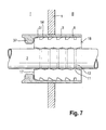
- Fig. 7 shows schematically a further embodiment of a system according to the invention;
- Fig. 8 shows schematically a further embodiment of a system according to the invention;
- Fig. 9 shows schematically a further embodiment of a system according to the invention.
- Fig. 10 shows schematically a further embodiment of a system according to the invention; and
- Fig. 11 shows schematically a further embodiment of a system according to the invention.
- In the drawings, like parts have like references.
- Fig. 1 shows a
partition 1 which is for the sake of clarity shown with a part cut out. Thepartition 1 divides two compartments I, II. Thepartition 1 comprises an opening through which apipe 2 extends. Wherever in this specification a pipe is referred to below, the pipe may also be a duct or a cable. Aconduit sleeve 3 corresponds to the opening. It is also possible to consider theconduit sleeve 3 as fittingly and sealingly fixed to a circumference of the opening. The system comprises an elasticallydeformable plug 4 which is fittingly and sealingly insertable in theconduit sleeve 3 as shown in Fig. 1. Thepartition wall 1 may be a steel wall. Theconduit sleeve 3 may also be made of steel and may in fact comprise a steel tube. The steel tube may be welded into the opening of thepartition 1. Theplug 4 may comprise a single piece as suitable for situations where theplug 4 can be inserted into theconduit sleeve 3 before thepipe 2 extends through theconduit sleeve 3. However, as most often theplug 4 will be an assembly of at least two segmentallongitudinal parts 5. In that case, theplug 4 can also be formed and inserted when apipe 2 extends through theconduit sleeve 3, before insertion of theplug 4. The division between these two segmentallongitudinal parts 5 ofplug 4 in Fig. 1 is shown by a dashed line. A perspective view of onelongitudinal part 5 of theplug 4 is shown in Fig. 2. - Fig. 3 shows schematically a view of an
inner side 6 of alongitudinal part 5 of a system according to an embodiment of the invention. Two of suchlongitudinal parts 5 can together form aplug 4. The upper part UP and the lower part LP of Fig. 3 correspond to a cross-section along a longitudinal direction L of alongitudinal part 5. The cross-section shown in the upper part UP of Fig. 3 is shown enlarged in Fig. 4. The longitudinalsegmental part 5 is provided with an outer side 7. This outer side 7 comprises a number ofouter ribs 8 havingtops 8a spaced apart in the longitudinal direction of theplug 4 for realizing annular contact surfaces 9 (see Fig. 5) between theplug 5 and an innercircumferential wall 10 of theconduit sleeve 3. Theinner side 6 is comprised of a number ofinner ribs 11 havingtops 11a spaced apart in a longitudinal direction of theplug 4 for realizing annular contact surfaces 12 between theplug 4 and thepipe 2. The term "spaced apart" encompasses a situation in which ribs have a part that is unconnected to the neighboring rib. However, "spaced apart" does not exclude a situation in which the ribs are adjacent each other. - In this exemplary embodiment, the
inner side 6 is provided with a number ofhingeable surface areas 15 for facilitating compression of theplug 4 in the longitudinal direction L and a transverse movement of at least one of the inner 11 and/orouter ribs 8. Thishingeable surface area 15 is in Fig. 4 indicated by a circle represented by a dashed line. In this embodiment, thehingeable surface area 15 is provided by two adjacentsloped surfaces 14 of two adjacentinner ribs 11. In this example thehingeable surface area 15 is provided on theinner side 6. It can be seen that the inner side is provided with fourhingeable surface areas 15. It is of course also possible that theinner side 6 is provided with only onehingeable surface area 15. However, the morehingeable surface areas 15 are provided, the more compression of theplug 4 in the longitudinal direction is facilitated. Furthermore, the more hingeable surface areas are provided by two adjacentsloped surfaces 14 of two adjacentinner ribs 11, the larger the number ofinner ribs 11 that experience facilitation of a transverse movement. How thehingeable surface areas 15 result in the possibility of sealing dynamically is explained later. At this stage it is pointed out that although thehingeable surface areas 15 are in this example shown to be provided on theinner side 6, one or more hingeable surface areas may also, or alternatively, be provided on the outer side 7. - At this stage the longitudinal
segmental parts 5 are described in more detail. Eachinner rib 11 has preferably the shape of a trapezium. Each of theinner ribs 11 is provided with an abuttingsurface 13 that extends in the longitudinal direction L and that, in use, abuts thepipe 2. Eachinner rib 11 is on either side of the abuttingsurface 13 provided with asloped surface 14 which extends away from the abuttingsurface 13. The slope of eachsloped surface 14 encloses an angle γ, with a transverse direction T of the segmentallongitudinal part 5 such that bending of eachinner rib 11 is substantially inhibited when the segmentallongitudinal part 5 is inserted. The insertion will be described later. One could also say that due to the shape of theinner rib 11 and the size of angle γ the inner ribs slide easily over thepipe 2 during insertion of theplug 4. - The slope of the sloped
surface 14 is substantially constant from the abuttingsurface 13, from which it extends up to a point P where it meets the slopedsurface 14 of an adjacentinner rib 11. Although it is shown that each slope of the slopedsurface 14 of one of theinner ribs 11 is substantially the same, it is also possible that the slopes vary somewhat. The slopped surfaces 14 of the two adjacentinner ribs 11 form together a V-shaped groove, i.e. the hingeable surface area. In the example shown, all slopes of allinner ribs 11 are substantially the same. The angle γ, is between 60 and 80 degrees, preferably between 65 and 77 degrees and even more preferably between 70 and 75 degrees. - One end of the
plug 4 and of eachlongitudinal part 5 may be denoted as thedistal end 17 as this end will be distal from the part of theconduit sleeve 3 at which theplug 4, or thelongitudinal parts 5, are inserted. The other end of theplug 4 and of each of thelongitudinal parts 5 may be denoted as theproximal end 18, as this end remains, relative to the distal end, proximal to the part of the conduit sleeve at which insertion of theplug 4 orlongitudinal part 5 occurs. - The
outer ribs 8 have each substantially the shape of a sawtooth 19 with a risingsurface 20 rising toward theproximal end 18. It is of course possible that only oneouter rib 8 has the shape of a sawtooth 19, or that some but not allouter ribs 8 have the shape of a sawtooth 19. In this example, allouter ribs 8 have the shape of a sawtooth 19. Thepart 21 of the risingsurface 20 adjoining the top 8a of the sawtooth 19 is, with respect to apart 22 of the risingsurface 20 located further from the top 8a, provided with a levelling which includes an angle α with the longitudinal direction L. Thepart 21 provides a pressing surface 23 that in use presses against theinner wall 10 of theconduit sleeve 3. The pressing surface 23 includes the angle α with the longitudinal direction L. This angle α is smaller than an angle β included by the surface of thepart 22 of the risingsurface 20 located further from the top 8a and the longitudinal direction L. The angle α is in any case larger than zero. - A meeting of the levelling
part 21 andpart 22 of the risingsurface 20 forms an outwardly directedbend 24 located in the risingsurface 20. Although, in this example, thebend 24 is formed by a meeting of straight surfaces, it is also possible that the bend is formed by a meeting of surfaces which merge more gradually with regard to the orientation of the surfaces. A fallingsurface 25 of the sawtooth 19 is provided with apart 26 located relatively far from the top 8a, which is designed so as to be inclined towards theproximal end 18 with respect to apart 27 of the fallingsurface 25 adjoining the top 8a. Thepart 27 of the fallingsurface 25 adjoining the top 8a of the sawtooth 19 includes an angle θ with a longitudinal direction L. The angle θ is larger than the angle ω which is included by thepart 26 of the fallingsurface 25 located further from the top 8a and the longitudinal direction L. - A
meeting 28 of thepart 27 of the fallingsurface 25 adjoining the top 8a of the sawtooth 19 and thepart 26 of the fallingsurface 25 located further from the top 8a forms an inwardly directedbend 28 located in the fallingsurface 25. The bend ormeeting 24 is in transverse direction located further outwardly than thebend 28. The note made above for the bend formed by meeting 24 also holds forbend 28. That is, a more gradual merge from thepart 27 of the fallingsurface 20 and thepart 26 is in this specification also understood to be a bend. It is further noted that it is also possible to provide a sawtooth 19 with abend 28 in the fallingsurface 25 without the risingsurface 20 of the sawtooth 19 comprising a levelling. - It is further visible in Fig. 4 that an imaginary transverse plane of the first type A intersects an
outer surface 29 on the outer side 7 and an abuttingsurface 13 on theinner side 6. Theouter surface 29 and the abuttingsurface 13 which both intersect the same imaginary transverse plane A, have a similar length in the longitudinal direction L. Over the entire length of the longitudinal direction of theouter surface 29 and/or the abuttingsurface 13, which both intersect the same imaginary transverse plane A, thatouter surface 29 and that abuttingsurface 13 are substantially parallel to each other. - Fig. 5 and Fig. 6 show schematically in more detail how the
longitudinal parts 5, and thus theplug 4, cooperate with theinner wall 10 of theconduit sleeve 3 and with thepipe 2 as received in the opening. Fig. 5 shows theinner wall 10 of theconduit sleeve 3 in cross-section, while the sealingplug 4 formed with the aid of thelongitudinal parts 5 is shown in a view such as would be seen when one half of theconduit sleeve 3 would have been removed. In general, when thepipe 2 extends through theconduit sleeve 3 before insertion of theplug 4 occurs, thelongitudinal parts 5 are tightly applied around thetube 2 and then, by a movement in the longitudinal direction L, forcefully pushed into thespace 30 between theinner wall 10 of theconduit sleeve 3 and thepipe 2. - As towards the
distal end 17, eachlongitudinal part 5 comprises on the outside 7 a run-inrib 31, insertion is facilitated. The run-inrib 31 extends up to an outer circumferential level that is in transverse direction less outward than an outer circumferential level up to which each otherouter rib 8 extends. - Upon further pressing in the longitudinal direction L, also
inner ribs 11 will contact theinner wall 10 of theconduit sleeve 3. Particularly the top 8a and at least a part of the pressing surface 23 will contact theinner wall 10. In order to overcome frictional forces occurring during the insertion, it is most often necessary to provide the longitudinal parts and/or theinner wall 10 of theconduit sleeve 3 and/orpipe 2 with a lubricant such as for instance Vaseline or soft soap. Particularly wheninner wall 10 is manufactured from concrete, this provides a good solution for reducing the high frictional forces. - The
plug 4, and thelongitudinal parts 5 should be manually insertable. However, in some cases, it may be necessary to move the sealingplug 4 as then formed by thelongitudinal parts 5 further distally in the direction L by using, for instance, a hammer. An assisting workpiece made of for instance wood, or a hard plastic, and having a shape such that it can freely be inserted into thespace 30, may be helpful for placing against theproximal end 18 of theplug 4 so that the hammer can hammer instead of the plug the workpiece distally into the longitudinal direction, so that thelongitudinal parts 5 of theplug 4 will not be damaged by the hammer. - It will be clear that when the
plug 4 has fully been inserted into the conduit sleeve, at least a part of each pressing surface 23 will be pressing against theinner wall 10 of theconduit sleeve 3. - Fig. 6 shows the
inner wall 10 of theconduit sleeve 3 in cross-section. Theplug 4 as inserted is presented as viewable in the same cross-sectional plane. Theannular contact surface 12 formed by the abuttingsurfaces 13 of thelongitudinal parts 5 are shown in dashed lines. It will be clear that theplug 4 can be inserted much further distally than shown in Fig. 5 and 6. - It will also be clear that any attempt to move the
plug 4 as inserted in theconduit sleeve 3 proximally, due to for instance a high pressure applied on thedistal end 17, the frictional forces at theannular contact surfaces plug 4 assembled fromlongitudinal parts 5 will resist movement up to a pressure of 7 bar as applied to thedistal end 17. - Without wishing to be bound by any theory, it is believed that the sealing system according to the invention works as follows in a dynamic fashion. The illustration of Fig. 6 might be helpful in understanding this possible working of the invention. When the
proximal end 18 anddistal end 17 of theplug 4, either as a one-piece plug, or as composed oflongitudinal parts 5, are compressed to each other, thehingeable surface area 15 responds in the sense that the two adjacentsloped surfaces 14 of two adjacentinner ribs 11, tend to enclose a smaller angle than before the compression. The twoinner ribs 11 to which the adjacentsloped surfaces 14 belong, experience a transverse inward force. The width of the annular contact surfaces 12 will as a result thereof increase. The width is a dimension of the annular contact surfaces in the longitudinal direction. This improves the sealing between theplug 4 and the surface ofpipe 2. However, aspipe 2 is not giving way, thepipe 2 exerts a reaction force onto theinner ribs 11. A response of theplug 4 is that theouter ribs 8 are pushed outwardly in a transverse direction, i.e. radially outwardly in this example. As a consequence thereof, a larger surface area of the pressing surface 23 will contact theinner wall 10 of theconduit sleeve 3. In other words, the width of theannular contact surface 9 will also increase. Also in this case the width is dimension in longitudinal direction of the annular contact surfaces 9. Consequently, the sealing between theplug 4 and theinner wall 10 of theconduit sleeve 3 is also greatly improved. - It will easily be understood that when the compression of the
plug 4 in the longitudinal direction L ceases, theplug 4 will tend to relax back towards its position that it had before the compression occurred. As such, the system responds dynamically upon compression of the plug in the longitudinal direction by improving the sealing integrity when the pressures exerted on the distal and proximal ends of the plug increase. - The plug remains somewhat flexible when uncompressed, allowing for vibration and shock absorption and a relatively low load applied to the pipe and inner wall of the conduit.
- Figs. 7 to 11 show further embodiments of a system according to the invention. In these embodiments the system further comprises a blocking
element 37 for hindering, when in use an external pressure gradient is present between both ends of the plug, movement of the downstream end of the plug downstream the pressure gradient. - Fig. 7 shows an embodiment of a system according to the invention as suitable in a situation wherein the hazardous side of the
partition 1 is known. In this situation a high pressure is expected to occur, when it occurs, in compartment II rather than in compartment I. The system comprises a blockingelement 37 for hindering, when in use an external pressure gradient is present between both ends 17, 18 of theplug 4, movement of thedownstream end 17 of theplug 4 downstream the pressure gradient. In other words when a very high pressure is present in compartment II and a low pressure is present in compartment I, theplug 4 will be compressed by movement ofproximal end 18 towardsdistal end 17. When the pressure in compartment II is thus very high, the plug will compress and theannular contact surfaces embodiment blocking element 37 is fixed to theconduit sleeve 3. In fact, in this embodiment the blockingelement 37 may even be considered as a part of theconduit sleeve 3. Although the blockingelement 37 may be welded to theconduit sleeve 3, it is preferred that theconduit sleeve 3 and the blockingelement 37 are formed by a milling process. Inner wall of theconduit sleeve 3 has preferably a surface with a low coefficient of friction. The surface may have been polished. This facilitates movement ofproximal end 18 towardsdistal end 17 and thus compression of theplug 4 in the longitudinal direction L. In this embodiment, the blockingelement 37 is substantially annularly shaped. A side of the blockingelement 37 facing thedistal end 17 of theplug 4, may at least partly have a shape that matches the shape of thedistal end 17 and the runningrib 31 of theplug 4. It is further important to note that the blocking element should not extend radially inward too much, to avoid contact withpipe 2 not only whenpipe 2 has been inserted in theconduit sleeve 3 but also when thepipe 2 is being inserted in theconduit sleeve 3. To avoid any damage topipe 2 should thepipe 2 make contact with blockingelement 37, the blocking element has edges which are rounded off. - Another embodiment of a system according to the invention is shown in Fig. 8. This embodiment is also suitable for a situation wherein the hazardous side is known, i.e. the high pressure is expected to occur in compartment II rather than in compartment I. In this embodiment, the
conduit sleeve 3 and the blockingelement 37 are separate pieces.Conduit sleeve 3 is provided with acollar 3a that extends radially outward from an end of theconduit sleeve 3 by which in use thedistal end 17 of the plug will be surrounded. The blockingelement 37 may comprise two parts that form together in use an annular retainer ring. This ring can be fixed aroundpipe 2 and to thecollar 3a ofconduit sleeve 3, once the pipe has been inserted, by for instance making use of bolts and nuts and suitably aligned bore holes in respectivelyretainer ring 37 andcollar 3a. Although it is shown that the blocking element can extend radially inward a little bit further and even very close topipe 2, it is still preferred that a retainer ring has a much smaller radial inward length. It is also preferred that the edges of the retainer ring facing thepipe 2 are rounded off. Ifconduit sleeve 3 happens to be a very long conduit sleeve, i.e. much longer than the length ofplug 4, it is preferred that a rubber sleeve is inserted first in the annular space between the inner wall of theconduit sleeve 3 and thepipe 2 before fixing the blockingelement 37. This rubber sleeve (not shown in Fig. 8) surroundspipe 2 and ensures that in the case of a very high pressure in compartment II as opposed to the pressure in compartment I, plug 4 does not need to move through the entire length of theconduit sleeve 3 before compression of theplug 4 occurs. Instead, but compression can start almost straight away, leading to a fast response of the dynamic sealing system. An improvement of the sealing integrity may further be in line with the mechanism as proposed when discussing Fig. 6. - Fig. 9 shows an embodiment of the system according to the invention that is suitable for a situation wherein it is unknown from which side of the partition 1 a hazardous event may approach the
conduit sleeve 3. This embodiment is particularly suitable for resisting a fire that may break out on either side of thepartition 1. The system comprises twoplugs 4. One of those twoplugs 4 is inserted from compartment I into theconduit sleeve 3 and the other one of theplugs 4 is inserted from compartment II into theconduit sleeve 3. In this embodiment, the blockingelement 37 is situated between the twoplugs 4. Although it is possible that the blockingelement 37 is again a retainer ring that is for instance welded to aninner wall 10 of theconduit sleeve 3, it is, as shown, also possible that the opening inpartition 1 is actually smaller than the diameter of theconduit sleeve 3 which is coaxially welded around a circumference of the smaller opening in thepartition 1. A part of thepartition 1 is then within theconduit sleeve 3 acting as a retainer ring, i.e. as a blockingelement 37. Although, again the blocking element as shown extends radially inward to a rather large extent, it is preferred that the radial inward length of the blocking element is somewhat shorter. - Fig. 10 shows an embodiment of a system according to the invention, that is also suitable for a situation in which one does not know from which side the hazardous event, like for instance a fire, could approach the
conduit sleeve 3. The system comprises again blockingelements 37 which are, as shown, fixable to theconduit sleeve 3 in a way described when the embodiment of Fig. 8 is discussed. It is preferred that the volume of the air entrapped in the conduit sleeve between thedistal end 17 of the twoplugs 4, is as short as possible. This may be achieved by providing aconduit sleeve 3 having a length that is just a little bit more than the total length of twoplugs 4, or by insertion of a rubber sleeve (shown in dashed line) in theconduit sleeve 3 so that the sleeve is positioned between the twoplugs 4. The air gap between theplugs 4 works as thermal insulation. If as a result of thermal expansion the pressure of the air in the air gap is built up, the air gap itself may work as a blocking element, facilitating compression of the plug that experiences a high pressure on theproximal end 18. This may even occur without the thermal expansion. In particular, in situations where the volume of the air gap is small, a slight further reduction of that volume, will raise the pressure of the air trapped in the gap. The gap may then act as a blocking element. - Finally, Fig. 11 shows an embodiment of a system according to the invention, wherein the conduit sleeve itself is rather short. In this embodiment the
plugs 4 are each provided with an annular slot that extends from the outer side of theplug 4 inwardly in a transverse direction. This slope is provided between the outer rib that is closest to theproximal end 18 of theplug 4 and theproximal end 18 itself. After insertion of theplug 4 this annular slot can as shown receive the blockingelement 37 which is further fixable to thecollar 3a ofconduit sleeve 3, as described when discussing the embodiment shown in Fig. 8. - It will be clear that a blocking
element 37 that is fixable to the conduit sleeve is preferably a multiple part element or at least an element that can surround a pipe without the need for sliding the blocking element over the pipe at one of the ends of the pipe. - A further blocking
element 37 may be provided betweenplugs 4 as shown, but this is not necessary. - When an explosion occurs in compartment II, the embodiment shown in Fig. 9, Fig. 10 and Fig. 11 will ensure that at least the plug present in the conduit sleeve and extending or facing the compartment I, will remain in the
conduit sleeve 3 when the complete partition is moved into the direction of compartment I along the longitudinal direction L. The embodiment shown in Fig. 10 and Fig. 11 will hold both theplugs 4 independent of the direction into whichpartition 1 is blasted along the longitudinal direction L. A particular advantage is that there is not only a dynamic response of the sealing system available, but also that in a situation wherein the entire partition is moved in a longitudinal direction L due to for instance an explosion, theconduit sleeve 3 including theplugs 4 will equally move up withpartition 1 during that movement. - Elastic material employed for the production of the segmental
longitudinal parts 5, i.e. for theplug 4, is preferably of a fire resistant quality. The rubber may be designed such that it expands upon exposure to elevated temperatures. It is also possible to use silicon rubber. A suitable EPDM may also be employed. The hardness may, for instance, be 70 Shore A. Any rubber with sufficient flexibility and a compression set similar to the compression set of EPDM is suitable. Also electrically conductive rubber is among the possibilities. During the manufacture of the longitudinal parts, use will usually be made of a mold suitable for this purpose. Such a production process is known per se. For instance, injection molding or compression molding may be used. The blocking element may be of metal, but in cases where the blocking element is fixable to theconduit sleeve 3 these may also be made of a hard plastic, such as for instance polyetherimide (PEI) or, alternatively, polyethersulfonamide (PES). - The invention is not limited to the embodiment shown above. It is for instance possible that the plugs are suitable for sealing a conduit sleeve through which a plurality of pipes extend. Further reference is made to
WO 2004/111513 , in particular the figures for plugs designed for filling space in a conduit through which more than one pipe extends. - Although, preferably, the sealing
plug 4 has a substantially cylindrical design, a deviation from this shape is also among the possibilities. Thus, the system can be designed such that the system is suitable for conduit sleeves which are quadrangular and/or rectangular. Embodiments suitable for multiangular conduit sleeves are not precluded either. Even embodiments for other non-circular, for instance, oval shaped conduit sleeves, are among the possibilities. The same holds true for the suitability with regard to the pipes and cables and ducts to be fed through the conduit sleeve. The system can be designed such that, in use, pipes and the like with a cross-section deviating from a circular shape can be enclosed by the plug. If desired, the skilled person will be able to adjust the dimensions to the required circumstances. - The way the blocking element is fixed or fixable to the conduit sleeve can be according to many different mechanisms.
- All such variations are understood to fall within the scope of the invention as defined by the appended claims.
Claims (25)
- A system for dynamically sealing an opening through which at least one pipe, cable or duct extends via a conduit sleeve which is fittingly and sealingly fixed to a circumference of the opening or which corresponds to the opening, wherein the system comprises at least an elastically deformable plug which is fittingly and sealingly insertable in the conduit sleeve, the plug having two ends, an outer side and an inner side, each end having dimensions that allow for fitting of that end in the conduit sleeve, the outer side comprising a number of outer ribs having tops spaced apart in a longitudinal direction of the plug for realising annular contact surfaces between the plug and an inner circumferential wall of the conduit sleeve, the inner side comprising a number of inner ribs having tops spaced apart in the longitudinal direction of the plug for realising annular contact surfaces between the plug and the at least one pipe, cable or duct, wherein the inner side and/or the outer side is provided with at least one hingeable surface area for facilitating compression of the plug in the longitudinal direction and a transverse movement of at least one of the inner or outer ribs.
- A system according to claim 1, wherein the hingeable surface is provided by two adjacent sloped surfaces of two adjacent ribs.
- A system according to claim 1 or 2, wherein the hingeable surface is provided on the inner side.
- A system according to any one of the previous claims, wherein the plug is an assembly of at least two segmental longitudinal parts.
- A system according to any one of the previous claims, wherein the system comprises the conduit sleeve.
- A system according to claim 5, wherein the inner wall of the conduit sleeve is provided with a surface that has a low friction coefficient.
- A system according to any one of the previous claims, wherein the system further comprises a blocking element for hindering, when in use an external pressure gradient is present between both ends of the plug, movement of the downstream end of the plug downstream the pressure gradient.
- A system according to claim 7, wherein the blocking element is fixable within or to the conduit sleeve.
- A system according to claim 7, wherein the blocking element is fixed within or to the conduit sleeve.
- A system according to any one of claims 7-9, wherein the blocking element comprises a substantially ring shaped element.
- A system according to any one of the previous claims, wherein the system comprises two plugs which are each according to the plug as described in any one of the claims 1-4.
- A system according to claim 11, wherein the two plugs as described in any one of the claims 1-4 are situated in the conduit sleeve and a blocking element as described in any one of the claims 7-10 is situated in the conduit sleeve between the two plugs.
- A system according to any one of claims 7-12, wherein the system comprises at least two blocking elements for hindering, in use, relative to the conduit simultaneous and equal movement of both ends of the plug downstream an external pressure gradient.
- A transit system comprising a conduit sleeve through which at least one pipe, cable or duct extends such that a longitudinal direction of the conduit sleeve and a longitudinal direction of the at least one tube or duct are substantially parallel to each other, wherein the system further comprises at least an elastically deformable plug which is fittingly and sealingly inserted in the conduit sleeve, the plug having two ends, an outer side and an inner side, each end having dimensions that allow for fitting of that end in the conduit sleeve, the outer side comprising a number of outer ribs having tops spaced apart in a longitudinal direction of the plug for realising annular contact surfaces between the plug and an inner circumferential wall of the conduit sleeve, the inner side comprising a number of inner ribs having tops spaced apart in the longitudinal direction of the plug for realising annular contact surfaces between the plug and the at least one pipe, cable or duct, wherein the inner side and/or the outer side is provided with at least one hingeable surface area for facilitating compression of the plug in the longitudinal direction and a transverse movement of at least one of the inner or outer ribs.
- A transit system according to claim 14, wherein the hingeable surface is provided by two adjacent sloped surfaces of two adjacent ribs.
- A transit system according to claim 14 or 15, wherein the hingeable surface is provided on the inner side.
- A transit system according to any one of the previous claims 14-16, wherein the plug is an assembly of at least two segmental longitudinal parts.
- A transit system according to any one of the previous claims 14-17, wherein the inner wall of the conduit sleeve is provided with a surface that has a low friction coefficient.
- A transit system according to any one of the previous claims, wherein the system further comprises a blocking element for hindering, when in use an external pressure gradient is present between both ends of the plug, movement of the downstream end of the plug downstream the pressure gradient.
- A transit system according to claim 19, wherein the blocking element is fixable within or to the conduit sleeve.
- A transit system according to claim 19, wherein the blocking element is fixed within or to the conduit sleeve.
- A transit system according to any one of claims 19-21, wherein the blocking element comprises a substantially ring shaped element.
- A transit system according to any one of the previous claims, wherein the system comprises two plugs which are each according to the plug as described in any one of the claims 14-17, wherein the two plugs are situated in the conduit sleeve and a blocking element as described in any one of the claims 19-22 is situated in the conduit sleeve between the two plugs.
- A transit system according to claim 19, wherein the system comprises at least two blocking elements as described in any one of the claims 19-22 for hindering, in use, relative to the conduit, simultaneous and equal movement of both ends of the plug downstream an external pressure gradient.
- Method for sealing a space in a conduit sleeve between an inner wall of the conduit sleeve and at least one pipe, tube or duct which extends through the conduit sleeve, wherein the method comprises:• providing an elastically deformable plug which is fittingly and sealingly insertable in the conduit sleeve, the plug having two ends, an outer side and an inner side, each end having dimensions that allow for fitting of that end in the conduit sleeve, the outer side comprising a number of outer ribs having tops spaced apart in a longitudinal direction of the plug for realising annular contact surfaces between the plug and an inner circumferential wall of the conduit sleeve, the inner side comprising a number of inner ribs having tops spaced apart in the longitudinal direction of the plug for realising annular contact surfaces between the plug and the at least one pipe, cable or duct, wherein the inner side and/or the outer side is provided with at least one hingeable surface area for facilitating compression of the plug in the longitudinal direction and a transverse movement of at least one of the inner or outer ribs;• inserting the plug in the conduit sleeve;• providing and applying a blocking element for hindering movement of one end of the plug after insertion of the plug into the conduit sleeve.
Priority Applications (11)
| Application Number | Priority Date | Filing Date | Title |
|---|---|---|---|
| EP06005629A EP1837573B1 (en) | 2006-03-20 | 2006-03-20 | System for dynamically sealing a conduit sleeve through which a pipe or cable extends |
| ES06005629T ES2394649T3 (en) | 2006-03-20 | 2006-03-20 | System to dynamically seal a conduit sleeve through which a tube or cable extends |
| PCT/EP2007/002478 WO2007107342A1 (en) | 2006-03-20 | 2007-03-20 | System for dynamically sealing a conduit sleeve through which a pipe or cable extends |
| EP13151613.0A EP2584236B1 (en) | 2006-03-20 | 2007-03-20 | System for dynamically sealing a conduit sleeve through which a pipe or cable extends |
| EP07711984.0A EP2005051B1 (en) | 2006-03-20 | 2007-03-20 | System for dynamically sealing a conduit sleeve through which a pipe or cable extends |
| JP2009500766A JP4890608B2 (en) | 2006-03-20 | 2007-03-20 | A system for dynamically sealing a conduit sleeve into which a pipe or cable is inserted |
| US12/225,346 US9528636B2 (en) | 2006-03-20 | 2007-03-20 | System for dynamically sealing a conduit sleeve through which a pipe or cable extends |
| NO20084360A NO343871B1 (en) | 2006-03-20 | 2008-10-17 | System for dynamic sealing of a sleeve through which a pipe or cable is drawn |
| JP2011231512A JP5346067B2 (en) | 2006-03-20 | 2011-10-21 | A system for dynamically sealing a conduit sleeve into which a pipe or cable is inserted |
| NO20130235A NO343749B1 (en) | 2006-03-20 | 2013-02-13 | System for dynamic sealing of a sleeve |
| US13/794,175 US20130234405A1 (en) | 2006-03-20 | 2013-03-11 | System for dynamically sealing a conduit sleeve through which a pipe or cable extends |
Applications Claiming Priority (1)
| Application Number | Priority Date | Filing Date | Title |
|---|---|---|---|
| EP06005629A EP1837573B1 (en) | 2006-03-20 | 2006-03-20 | System for dynamically sealing a conduit sleeve through which a pipe or cable extends |
Publications (2)
| Publication Number | Publication Date |
|---|---|
| EP1837573A1 true EP1837573A1 (en) | 2007-09-26 |
| EP1837573B1 EP1837573B1 (en) | 2012-09-12 |
Family
ID=36763837
Family Applications (3)
| Application Number | Title | Priority Date | Filing Date |
|---|---|---|---|
| EP06005629A Active EP1837573B1 (en) | 2006-03-20 | 2006-03-20 | System for dynamically sealing a conduit sleeve through which a pipe or cable extends |
| EP13151613.0A Active EP2584236B1 (en) | 2006-03-20 | 2007-03-20 | System for dynamically sealing a conduit sleeve through which a pipe or cable extends |
| EP07711984.0A Active EP2005051B1 (en) | 2006-03-20 | 2007-03-20 | System for dynamically sealing a conduit sleeve through which a pipe or cable extends |
Family Applications After (2)
| Application Number | Title | Priority Date | Filing Date |
|---|---|---|---|
| EP13151613.0A Active EP2584236B1 (en) | 2006-03-20 | 2007-03-20 | System for dynamically sealing a conduit sleeve through which a pipe or cable extends |
| EP07711984.0A Active EP2005051B1 (en) | 2006-03-20 | 2007-03-20 | System for dynamically sealing a conduit sleeve through which a pipe or cable extends |
Country Status (6)
| Country | Link |
|---|---|
| US (2) | US9528636B2 (en) |
| EP (3) | EP1837573B1 (en) |
| JP (2) | JP4890608B2 (en) |
| ES (1) | ES2394649T3 (en) |
| NO (2) | NO343871B1 (en) |
| WO (1) | WO2007107342A1 (en) |
Cited By (9)
| Publication number | Priority date | Publication date | Assignee | Title |
|---|---|---|---|---|
| WO2008023058A1 (en) * | 2006-08-25 | 2008-02-28 | Beele Engineering B.V. | System for dynamically sealing at least one conduit through which a pipe or cable extends |
| EP3037695A1 (en) * | 2014-12-23 | 2016-06-29 | WEDI GmbH | Sealing insert for a water outlet |
| US9528636B2 (en) | 2006-03-20 | 2016-12-27 | Beele Engineering B.V. | System for dynamically sealing a conduit sleeve through which a pipe or cable extends |
| US9722404B2 (en) | 2013-02-14 | 2017-08-01 | Beele Engineering B.V. | System for sealingly holding cables which extend through an opening |
| EP2639058A3 (en) * | 2012-03-14 | 2017-12-27 | Promat GmbH | Fire protection tube cuff |
| US10422427B2 (en) | 2010-05-25 | 2019-09-24 | Beele Engineering B.V. | Assembly and a method for providing in an opening sealing system |
| US10544884B2 (en) | 2012-08-30 | 2020-01-28 | Beele Engineering B.V. | Sealing system for an annular space |
| CN113889945A (en) * | 2021-10-09 | 2022-01-04 | 中船黄埔文冲船舶有限公司 | Marine shore power cable threading pipe |
| US11454336B1 (en) * | 2021-12-30 | 2022-09-27 | Ub Eng Co., Ltd. | Support device of vacuum pipe |
Families Citing this family (41)
| Publication number | Priority date | Publication date | Assignee | Title |
|---|---|---|---|---|
| EP2696124B1 (en) | 2010-08-10 | 2015-09-30 | Beele Engineering B.V. | System for embedding a sealable conduit for ducting a tube or cable in a wall or floor which is to be produced by a casting process and method for embedding such a conduit |
| DE102011004560A1 (en) * | 2011-02-23 | 2012-08-23 | Behr Gmbh & Co. Kg | Arrangement for sealing line interfaces in a motor vehicle |
| CN102720894B (en) * | 2011-03-30 | 2014-08-13 | 江苏省镇江船厂有限责任公司 | Deck penetration piece for ship pipe and penetration method |
| JP6265519B2 (en) * | 2012-10-18 | 2018-01-24 | 三菱重工業株式会社 | Sealing device |
| CN102927374B (en) * | 2012-10-24 | 2014-09-17 | 中国船舶重工集团公司第七○二研究所 | Water seal treatment device for ship model deck lead opening |
| GB2507496B (en) * | 2012-10-30 | 2016-12-07 | Variopool B V | Swimming pool with adjustable pool floor system |
| JP6199060B2 (en) * | 2013-03-28 | 2017-09-20 | 大和ハウス工業株式会社 | Spacer closing spacer |
| EP2827465A1 (en) * | 2013-07-17 | 2015-01-21 | HILTI Aktiengesellschaft | Cable gland, method for producing a cable gland and method for mounting a cable gland |
| US9989252B2 (en) * | 2013-08-22 | 2018-06-05 | Noritz Corporation | Exhaust adapter, exhaust structure for water heater, and method for installing exhaust adapter |
| NL1040476C2 (en) * | 2013-10-31 | 2015-05-04 | Beele Eng Bv | A pipe transit system. |
| US9517369B2 (en) | 2014-08-12 | 2016-12-13 | Stephen Samouhos | Fire stop conduit |
| SE1451192A1 (en) * | 2014-10-07 | 2016-03-08 | Mct Brattberg Ab | Insert block half |
| DE102014115005A1 (en) * | 2014-10-15 | 2016-04-21 | Skoberne Schornsteinsysteme Gmbh | building |
| CN104875955B (en) * | 2015-06-15 | 2016-11-30 | 浙江天衣机械有限公司 | Steel tube frame and steel pipe support device |
| NO341490B1 (en) * | 2015-06-18 | 2017-11-27 | Braathen Thor F | A cabinet and method for making a cabinet |
| CA2933720C (en) * | 2015-06-23 | 2018-03-13 | Evolution Engineering Inc. | Sealing gasket and method for creating same |
| DE102015112286A1 (en) * | 2015-07-28 | 2017-02-02 | R. Stahl Schaltgeräte GmbH | Explosion-proof arrangement for bolt bushing and method for the production thereof |
| US20170030490A1 (en) * | 2015-07-28 | 2017-02-02 | Hilti Aktiengesellschaft | Air, acoustic and/or fire sealing sleeve insert and air, acoustic and/or fire sealing device |
| KR101841146B1 (en) * | 2015-08-10 | 2018-03-22 | 임장호 | Fire proof cover for piping of building |
| EP3150891A1 (en) * | 2015-09-29 | 2017-04-05 | HILTI Aktiengesellschaft | Conduit feed-through for feeding conduits through a component |
| WO2017059176A1 (en) * | 2015-09-30 | 2017-04-06 | Specified Technologies Inc. | Self-adjusting firestopping sleeve apparatus |
| GB2543289B (en) * | 2015-10-13 | 2022-03-02 | Snug Solutions Ltd | A surrounding member for a pipe |
| EP3190670B1 (en) * | 2016-01-07 | 2021-03-24 | Aptiv Technologies Limited | Conduit seal and vibration damper |
| SE539578C2 (en) * | 2016-04-05 | 2017-10-17 | Mct Brattberg Ab | Insert half, and insert block comprising two of said insert halves |
| WO2018000074A1 (en) * | 2016-06-27 | 2018-01-04 | Volvo Group Canada Inc. | Cable sealing device for an electrical junction box |
| US10349589B2 (en) | 2016-09-08 | 2019-07-16 | Hemex Health, Inc. | Diagnostics systems and methods |
| US10557573B2 (en) * | 2016-11-04 | 2020-02-11 | United Technologies Corporation | Feed through seals and fittings |
| JP6468537B2 (en) * | 2016-11-30 | 2019-02-13 | 矢崎総業株式会社 | Manufacturing method of wire harness |
| EP3361586B1 (en) * | 2017-02-10 | 2020-12-02 | Robert Bosch GmbH | Grommet for sealing a cable in a cable bushing and grommet arrangement |
| CN106704757B (en) * | 2017-02-23 | 2019-04-30 | 江苏丰禾机械制造股份有限公司 | A kind of independent sealed compensator of piping lane system-specific |
| GB2565232B (en) * | 2017-08-01 | 2022-04-27 | Bae Systems Plc | Cable position stopper |
| KR102446954B1 (en) * | 2017-08-16 | 2022-09-23 | 대우조선해양 주식회사 | Cable penetration structure for subsea wiring |
| US10767803B2 (en) * | 2017-09-14 | 2020-09-08 | Operations Technology Development, Nfp | Split cap safety plug |
| NL2019585B1 (en) | 2017-09-20 | 2019-03-28 | Beele Eng Bv | System for sealing in an opening a space around a pipe |
| DK3676524T3 (en) * | 2017-09-26 | 2023-02-06 | Luciano Lombardi | A SAFETY DEVICE FOR THE PASSAGE OF PIPES ON BOATS |
| DE102018105870B4 (en) * | 2018-03-14 | 2021-04-29 | Dipl.-Ing. H. Horstmann Gmbh | Water-repellent grommet |
| IL260942B (en) * | 2018-08-01 | 2019-09-26 | Karpel Eran | Transferring appartus for pipeline and electricity wiring insertion into residential secured spaces |
| CN110195801B (en) * | 2019-06-14 | 2020-12-11 | 上海外高桥造船有限公司 | Maritime work equipment |
| CN110469722A (en) * | 2019-08-30 | 2019-11-19 | 广船国际有限公司 | Plastics pass through cabin part |
| CN111262211B (en) * | 2020-03-17 | 2020-10-27 | 深圳市泰士特科技股份有限公司 | Cable conduit sealing system module |
| US20220240409A1 (en) * | 2021-01-22 | 2022-07-28 | Dell Products L.P. | Cable Sealing Apparatus And Methods |
Citations (10)
| Publication number | Priority date | Publication date | Assignee | Title |
|---|---|---|---|---|
| GB1026392A (en) * | 1961-11-24 | 1966-04-20 | Rheinisches Metallwerk Gmbh | Pipe connections |
| FR2169219A1 (en) * | 1972-01-25 | 1973-09-07 | Wunderlich Heinz | |
| FR2192264A1 (en) * | 1972-07-06 | 1974-02-08 | Freudenberg Carl | PTFE Wall seal - for cable or pipe lead ins, with compensating grooves and/or folds |
| GB2057595A (en) | 1979-03-30 | 1981-04-01 | Avon Ind Polymers Bradford On | Seal Assembly |
| DE3443284A1 (en) * | 1984-11-28 | 1986-05-28 | Dipl.-Ing. Dr. E. Vogelsang GmbH & Co KG, 4352 Herten | End closure arrangement on a unit consisting of a cable duct and a drawn-in tube bundle consisting of cable-guidance tubes |
| DE20002216U1 (en) * | 1999-02-15 | 2000-04-27 | Liv Plastika Predelava Plastik | Connection of a drain pipe to a flush-mounted cistern in the toilet |
| EP1101992A2 (en) * | 1999-11-19 | 2001-05-23 | HILTI Aktiengesellschaft | Seal sleeve |
| CH691273A5 (en) * | 1996-08-09 | 2001-06-15 | Hanspeter Gubelmann | Sealed water or gas supply line input for building |
| US20040045233A1 (en) * | 2000-11-30 | 2004-03-11 | Beele Johannes Alfred | Sealing system and gasket therefor |
| WO2004111513A1 (en) | 2003-06-18 | 2004-12-23 | Beele Engineering B.V. | System for sealing a space between a tubular opening and a tube |
Family Cites Families (150)
| Publication number | Priority date | Publication date | Assignee | Title |
|---|---|---|---|---|
| US2032492A (en) * | 1934-10-31 | 1936-03-03 | Goodrich Co B F | Pipe joint assembly |
| US2202617A (en) * | 1939-02-24 | 1940-05-28 | A C Horn & Company | Method of sealing conduits |
| US2271777A (en) * | 1939-04-25 | 1942-02-03 | Goodrich Co B F | Sealing structure |
| US2396836A (en) | 1942-01-23 | 1946-03-19 | Adel Prec Products Corp | Conduit supporting block |
| US2355742A (en) | 1942-09-21 | 1944-08-15 | Adel Prec Products Corp | Conduit supporting block |
| US2404531A (en) | 1943-12-13 | 1946-07-23 | Adel Prec Products Corp | Conduit supporting block |
| US2354919A (en) | 1944-04-08 | 1944-08-01 | Leroy Robert Bowles | Multiple clamping device |
| US2448769A (en) * | 1945-09-07 | 1948-09-07 | James M W Chamberlain | Fluid-coupling assembly |
| US2819099A (en) * | 1953-06-12 | 1958-01-07 | Westinghouse Air Brake Co | Flange union fitting with contractible lined wedge |
| US2896974A (en) | 1957-04-02 | 1959-07-28 | Gen Motors Corp | Bell and spigot joint with plural flexible lip type seal |
| BE579697A (en) | 1958-06-20 | 1959-10-01 | Robert Alexander De Vienne | Watertight tightening connection for electric cables. |
| US3016722A (en) | 1959-05-26 | 1962-01-16 | Ford Motor Co | Slip joint seal |
| US3067425A (en) * | 1959-11-09 | 1962-12-11 | Goodrich Co B F | Flying suit helmet with penetrable sealing closure structure |
| US3048415A (en) * | 1960-12-05 | 1962-08-07 | Press Seal Gasket Corp | Pipe joint assembly |
| US3163448A (en) * | 1961-10-03 | 1964-12-29 | American Pipe & Constr Co | Conduit joint and seal member therefor |
| US3352212A (en) * | 1962-05-03 | 1967-11-14 | Dresser Ind | Well swab device |
| US3162412A (en) | 1962-08-06 | 1964-12-22 | E & R Lab Service Corp | Clamping structure for control tubing or the like |
| GB1083451A (en) | 1963-03-11 | 1967-09-13 | Allied Ironfounders Ltd | A sealing member and a pipe joint incorporating the same |
| US3206539A (en) | 1963-05-03 | 1965-09-14 | William D Kelly | Metal sheathed electrical conductors |
| US3165324A (en) | 1963-09-30 | 1965-01-12 | William L Zopfi | Molded pipe joint seal |
| US3229026A (en) | 1964-07-30 | 1966-01-11 | Advance Transformer Co | Grommet and canister construction |
| US3331914A (en) * | 1965-09-24 | 1967-07-18 | M & W Electric Mfg Co Inc | Watertight sealing devices for electrical cables |
| US3489440A (en) | 1966-04-18 | 1970-01-13 | Lyckeaborgs Bruk Ab | Tight lead-through inlet frame device |
| US3578027A (en) * | 1969-07-30 | 1971-05-11 | William L Zopfi | Sealing plugs or closures |
| US3580988A (en) | 1969-08-12 | 1971-05-25 | Ampex | Grommet for speaker enclosure |
| US3702193A (en) * | 1971-02-22 | 1972-11-07 | Josam Mfg Co | Self-retaining and sealing joint gasketing sleeve |
| BE788705A (en) * | 1971-12-03 | 1973-01-02 | Formex Mfg Inc | DUCT TERMINATOR |
| DE2203370A1 (en) | 1972-01-25 | 1973-08-02 | Heinz Wunderlich | DEVICE FOR ANCHORING PIPELINE OUTLETS IN THE WALL |
| US3827704A (en) * | 1972-06-16 | 1974-08-06 | G Gillemot | Sealing grommet and plug for use with electrical cabling |
| US3811711A (en) * | 1972-10-03 | 1974-05-21 | Harsco Corp | Multiple concrete to plastic pipe adapter |
| US3793672A (en) * | 1972-12-06 | 1974-02-26 | Raychem Corp | Heat recoverable article and process |
| US3913928A (en) * | 1973-05-09 | 1975-10-21 | Seiichi Yamaguchi | Resilient joint |
| US3893919A (en) * | 1973-10-31 | 1975-07-08 | Josam Mfg Co | Adjustable top drain and seal |
| US4061344A (en) | 1976-06-23 | 1977-12-06 | General Signal Corporation | Fitting for penetration through fire rated barriers |
| US4075803A (en) * | 1976-06-24 | 1978-02-28 | Formex Manufacturing, Inc. | Split duct terminator |
| JPS5543712Y2 (en) * | 1976-09-02 | 1980-10-14 | ||
| US4086736A (en) * | 1976-12-16 | 1978-05-02 | Daniel International Corporation | Fire and liquid seals for pipes and conduits and method of forming same |
| FR2378909A1 (en) | 1977-02-01 | 1978-08-25 | Intellectual Trade Cy Sa | PROCESS FOR MAKING A FIRE-RESISTANT CROSS-TERMINAL AND PERFORMED IN ACCORDANCE WITH THIS PROCESS |
| NL177516C (en) * | 1978-09-12 | 1985-10-01 | Pidou Bv | SEALING CUFF. |
| JPS55134718U (en) * | 1979-03-16 | 1980-09-25 | ||
| JPS55165177U (en) * | 1979-05-17 | 1980-11-27 | ||
| JPS5616518U (en) * | 1979-07-17 | 1981-02-13 | ||
| NL8005711A (en) * | 1979-10-18 | 1981-04-22 | Tungum Hydraulics Ltd | PIPE COUPLING WITH AXIAL MOVING PARTS. |
| US4361721A (en) | 1980-05-21 | 1982-11-30 | Bell Telephone Laboratories, Incorporated | Splice case with tight sealing grommet |
| US4385777A (en) * | 1980-06-02 | 1983-05-31 | The Logsdon Foundation | Decorative escutcheon capable of inhibiting the propagation of noise |
| DE8018534U1 (en) | 1980-07-10 | 1981-01-15 | Licentia Patent-Verwaltungs-Gmbh, 6000 Frankfurt | Cable entry |
| JPS5751884U (en) * | 1980-09-11 | 1982-03-25 | ||
| US4419535A (en) | 1981-07-31 | 1983-12-06 | Hara Robert J O | Multi-cable conduit for floors and walls |
| US4426095A (en) * | 1981-09-28 | 1984-01-17 | Concrete Pipe & Products Corp. | Flexible seal |
| US4431243A (en) | 1982-07-28 | 1984-02-14 | The Bendix Corporation | Contact stop for an electrical connector |
| US4429886A (en) * | 1982-09-29 | 1984-02-07 | Concrete Pipe & Products Corp. | Flexible pipe gasket |
| AT384692B (en) | 1983-05-20 | 1987-12-28 | Werner Hauff | BUSHING FOR PIPES, LIKE CABLES, TUBES OR THE LIKE, THROUGH A WALL OPENING AND DEVICE FOR PRODUCING SUCH A THROUGHOUT IN A CONCRETE WALL |
| FR2547888B1 (en) * | 1983-06-22 | 1985-12-13 | Sabla Sa | IMPLANT SEALING RING FOR INTERLOCKING PIPES |
| EP0139337A3 (en) * | 1983-10-19 | 1986-07-30 | Pidou B.V. | Multi-part sealing system |
| US5020810A (en) | 1985-10-09 | 1991-06-04 | Jogler, Inc. | Liquid sight monitor with multi-contact insert |
| JPH0541868Y2 (en) | 1985-11-15 | 1993-10-22 | ||
| GB2186442B (en) | 1986-02-11 | 1990-03-14 | Hawke Cable Glands Ltd | Improved transit for cables and pipes |
| US4664421A (en) | 1986-08-29 | 1987-05-12 | Jones William D | Forgiving profile pipe gasket |
| NL8700204A (en) | 1987-01-28 | 1988-08-16 | Pidou Bv | SEALING DEVICE. |
| US4797122A (en) * | 1987-04-08 | 1989-01-10 | Daiichi Denshi Kogyo Kabushiki Kaisha | Drip-proof connector |
| JPH0693372B2 (en) | 1987-04-08 | 1994-11-16 | 第一電子工業株式会社 | Drip-proof connector |
| DE3727160C1 (en) | 1987-08-14 | 1988-09-08 | Plastoform Gmbh & Co Kg | Lead-through for cables through a wall opening |
| GB2221736B (en) * | 1988-08-10 | 1992-08-19 | Hawke Cable Glands Ltd | Apparatus for sealing a service duct |
| JPH0270490U (en) * | 1988-11-18 | 1990-05-29 | ||
| GB8830111D0 (en) | 1988-12-23 | 1989-02-22 | British Gas Plc | Method and system for enhancing service pipes |
| US4915422A (en) | 1989-01-06 | 1990-04-10 | The American Brass & Iron Foundry | Pipe coupling |
| NL8901597A (en) | 1989-06-23 | 1991-01-16 | Pidou Bv | TRANSIT DEVICE. |
| JPH0332272A (en) | 1989-06-29 | 1991-02-12 | Nec Corp | Signal transmitter |
| US4998896A (en) * | 1989-09-25 | 1991-03-12 | Amp Incorporated | Sealed stamped and formed pin |
| DE9000975U1 (en) | 1990-01-29 | 1990-04-05 | Wolff, Anton, Dipl.-Ing., 3492 Brakel, De | |
| AU630174B2 (en) | 1990-04-10 | 1992-10-22 | Csd International B.V. | System for the prevention of fire, water or (flue) gas and the like from propagating along cables |
| FR2675879B1 (en) | 1991-04-25 | 1993-12-31 | Vibrachoc | DEVICE FOR SUPPORTING PIPING ON THE PASSAGE OF A PARTITION AND ENSURING WATERPROOFING ON BOTH PARTS OF THE PARTITION. |
| IT1245816B (en) | 1991-05-23 | 1994-10-18 | Bertoldo & C Srl | GASKET FOR A COUPLING FOR PROTECTION TUBES FOR ELECTRIC CABLES AND COUPLING INCLUDING SUCH GASKET |
| NL9101637A (en) * | 1991-09-27 | 1993-04-16 | Csd Int Bv | FIRE-RESISTANT SYSTEM AND METHOD FOR TRANSFERRING AT LEAST A CABLE, PIPE OR THE LIKE, THROUGH A LIQUID AND GAS TIGHT, THROUGH AN OPENING OF A WALL. |
| DE4207666C2 (en) | 1992-03-11 | 1994-05-11 | Deutsche Aerospace Airbus | Device for fixing components |
| DE9204067U1 (en) | 1992-03-26 | 1992-07-23 | Betonbau Gmbh, 6833 Waghaeusel, De | |
| US5245131A (en) | 1992-03-27 | 1993-09-14 | At&T Bell Laboratories | Cabinets having improved cable entrance seal |
| DE9206312U1 (en) | 1992-05-11 | 1992-08-06 | Passavant-Werke Ag, 6209 Aarbergen, De | |
| DE4225916C2 (en) | 1992-08-05 | 1995-05-18 | Thyssen Polymer Gmbh | Sealing element for cable duct pipes |
| DE4305071A1 (en) | 1992-09-29 | 1994-08-25 | Klein Guenther Industriebedarf | Packing system for the passage of cables through screen walls |
| JPH0765661A (en) | 1993-08-23 | 1995-03-10 | Sumitomo Wiring Syst Ltd | Grommet divided in two |
| US5456050A (en) * | 1993-12-09 | 1995-10-10 | Construction Consultants & Contractors, Inc. | System to prevent spread of fire and smoke through wall-breaching utility holes |
| JP3054319B2 (en) | 1994-03-04 | 2000-06-19 | 矢崎総業株式会社 | Waterproof rubber stopper and manufacturing method thereof |
| JP3341442B2 (en) | 1994-03-07 | 2002-11-05 | 住友電装株式会社 | Grommet |
| GB9406362D0 (en) | 1994-03-30 | 1994-05-25 | Davidson Paul | Pipe muff system |
| EP0677894B1 (en) * | 1994-04-13 | 2001-09-05 | Sumitomo Wiring Systems, Ltd. | Sealing device and method for producing a waterproof connector |
| JP2962144B2 (en) | 1994-04-13 | 1999-10-12 | 住友電装株式会社 | Connector waterproof structure |
| SE515100C2 (en) | 1994-06-08 | 2001-06-11 | Forsheda Ab | Device for sealing a gap |
| JP2785695B2 (en) * | 1994-07-20 | 1998-08-13 | 住友電装株式会社 | Waterproof seal for connector |
| JP2976837B2 (en) | 1995-03-14 | 1999-11-10 | 住友電装株式会社 | Grommet |
| FI101498B1 (en) * | 1995-05-16 | 1998-06-30 | Uponor Bv | Sleeve connection for plastic pipes |
| DE29604662U1 (en) | 1996-03-13 | 1997-07-17 | Pt Poly Tec Gmbh | Connecting device |
| DE29605883U1 (en) | 1996-03-29 | 1996-07-18 | Svt System Service Gmbh | Cable insulation |
| JPH09284954A (en) * | 1996-04-05 | 1997-10-31 | Nikko Kogyo Kk | Moisture-proof grommet |
| JP3106961B2 (en) | 1996-06-07 | 2000-11-06 | 住友電装株式会社 | Waterproof structure of electrical box |
| GB2314396B (en) | 1996-06-21 | 1999-12-22 | British Gas Plc | Pipe liner |
| GB2315838A (en) | 1996-08-01 | 1998-02-11 | British Gas Plc | Apparatus and method for sealing a clearance between a host pipe and a liner pipe |
| US6224115B1 (en) | 1996-10-08 | 2001-05-01 | Delaware Capital Formation, Inc. | Bulkhead fitting for underground sump |
| US5954345A (en) * | 1996-10-10 | 1999-09-21 | Chrysler Corporation | Grommet for transmission oil fill tube |
| NL1008522C2 (en) | 1998-03-06 | 1999-09-07 | Beele Eng Bv | Transit device. |
| EP0987482A3 (en) * | 1998-09-14 | 2000-11-08 | Kröner GmbH Armaturen und Dichtungstechnik | House inlet for pipes |
| DE19901914A1 (en) | 1999-01-19 | 2000-07-20 | Luetze Friedrich Elektro | Holding device for cables routed through walls |
| US6180882B1 (en) | 1999-01-19 | 2001-01-30 | Thomas & Betts, International | Single and dual cable seal system |
| JP3540197B2 (en) * | 1999-05-18 | 2004-07-07 | 矢崎総業株式会社 | Waterproof connector |
| NL1012759C2 (en) * | 1999-08-02 | 2001-02-05 | Beele Eng Bv | Sealing assembly and sealing sleeve for this. |
| CN1102212C (en) | 1999-08-30 | 2003-02-26 | 赵洪海 | Insulating pipe bracket |
| SE515160C2 (en) | 1999-10-08 | 2001-06-18 | Roxtec Ab | Cable entry |
| DE19959185A1 (en) | 1999-12-08 | 2001-06-28 | Bethke Kunststofftechnik Gmbh | Cable entry |
| AT410734B (en) * | 2000-03-14 | 2003-07-25 | Bst Brandschutztechnik Doepfl | SEALING ELEMENT FOR A DEVICE FOR FIRE-PROOF PIPING OF PIPES THROUGH OPENING WALLS |
| DE10035006C1 (en) | 2000-07-19 | 2002-03-07 | Langmatz Lic Gmbh | Wall penetration for cables, comprising sealing pot and flange plate, includes silicone ring seal and annular chamber containing excess of setting silicone sealant |
| CA2319876A1 (en) * | 2000-09-19 | 2002-03-19 | Michael P. Sakno | Block for fire and smoke along a barrier penetrating member |
| US6494463B1 (en) * | 2000-11-06 | 2002-12-17 | Kurt J. Rank | Plug for sealing more than one size of hole |
| NL1016703C2 (en) | 2000-11-24 | 2002-05-27 | Beele Eng Bv | Feeding device. |
| DE20103785U1 (en) | 2001-03-05 | 2001-08-09 | Dts Pro Sys Gmbh | Sealing sleeve |
| DE20103786U1 (en) | 2001-03-05 | 2001-08-09 | Dts Pro Sys Gmbh | Sealing sleeve |
| JP2002343493A (en) * | 2001-05-18 | 2002-11-29 | Yazaki Corp | Terminal integrated type seal member |
| GB2380241B (en) * | 2001-07-12 | 2003-08-20 | Huntleigh Technology Plc | Connector |
| NL1018722C2 (en) | 2001-08-07 | 2003-02-10 | Beele Eng Bv | Fire-resistant system and method for passing at least one cable, tube or the like through an opening of a wall. |
| NL1019919C2 (en) | 2002-02-07 | 2003-08-08 | Beele Eng Bv | Pass-through device for sealingly passing a cable, tube, pipe and the like through an opening of a wall. |
| US6431215B1 (en) | 2002-03-05 | 2002-08-13 | Potter Co., Ltd. | Plug for use with a conduit having cables received in the conduit |
| US6575430B1 (en) * | 2002-04-10 | 2003-06-10 | National Coupling Company, Inc. | Hydraulic coupling with dovetail seal having multiple radial sealing surfaces |
| FR2843438B1 (en) | 2002-08-09 | 2005-02-11 | Amphenol Air Lb | DEVICE FOR MAINTAINING PIPING SYSTEMS |
| US7114303B2 (en) | 2002-11-15 | 2006-10-03 | 3M Innovative Properties Company | Cover assembly for a through-penetration |
| US6928777B2 (en) | 2002-11-15 | 2005-08-16 | 3M Innovative Properties Company | Method and apparatus for firestopping a through-penetration |
| DE10313989B4 (en) | 2003-03-27 | 2012-07-12 | Murrplastik Systemtechnik Gmbh | Grommet device |
| NL1023687C2 (en) | 2003-06-18 | 2004-12-21 | Beele Eng Bv | Seal for lead through, e.g. for pipe or cable in wall, has tips of ribs on outer and inner sides which are offset relative to each other |
| DE20310390U1 (en) | 2003-07-04 | 2004-11-11 | Pt-Poly-Tec Gmbh Vertrieb Und Herstellung Von Dichtungssystemen | Connection seal with ratchet teeth |
| KR101014703B1 (en) | 2003-07-15 | 2011-02-21 | 엘지전자 주식회사 | Method and apparatus for managing a defective area on optical disc |
| US6969799B2 (en) * | 2003-11-20 | 2005-11-29 | Sgc Technologies, L.L.C. | Poke through |
| SE526243C2 (en) | 2003-12-12 | 2005-08-02 | Roxtec Ab | Feed-through device for cables or pipes |
| JP4806395B2 (en) | 2004-02-27 | 2011-11-02 | グリーン, ツイード オブ デラウェア, インコーポレイテッド | Sealed electrical connector |
| US7410174B2 (en) | 2004-03-04 | 2008-08-12 | S & B Technical Products, Inc. | Restraining mechanical joint gasket for ductile iron pipe |
| DE102004034038A1 (en) | 2004-07-13 | 2006-02-09 | Yazaki Europe Ltd., Hemel Hempstead | Electrically conductive connection for operating between a cable end piece and a cable end with conductor and insulating sections has a connection end and connector clips |
| US7665256B2 (en) | 2004-08-24 | 2010-02-23 | 3M Innovative Properties Company | Method and apparatus for firestopping a through-penetration |
| DE202004017185U1 (en) | 2004-11-03 | 2006-03-23 | Doyma Gmbh & Co | Sealing device e.g. for line entering wall, has region of sealing body with reduced axial strength |
| DE102005002597B3 (en) | 2005-01-20 | 2006-08-03 | Bimed Teknik A.S., Büyükcekmece | Line holder for e.g. electrical cables has aligning components that are inserted into recesses and shift seal components along flat steel bars |
| US8262094B2 (en) | 2005-07-13 | 2012-09-11 | Beele Engineering B.V. | System for sealing a space between an inner wall of a tubular opening and at least one tube or duct at least partly received in the opening |
| SE0600367L (en) | 2006-02-17 | 2007-08-18 | Roxtec Ab | Cable restraint system |
| DE202006017659U1 (en) | 2006-03-18 | 2007-08-02 | Weidmüller Interface GmbH & Co. KG | Seal for a housing feedthrough for a cable |
| ES2394649T3 (en) | 2006-03-20 | 2013-02-04 | Beele Engineering B.V. | System to dynamically seal a conduit sleeve through which a tube or cable extends |
| TW200810265A (en) | 2006-05-31 | 2008-02-16 | Roxtec Ab | A plug unit for a cable entry |
| EP1892448B1 (en) | 2006-08-25 | 2009-08-19 | Beele Engineering B.V. | System for dynamically sealing at least one conduit through which a pipe or cable extends |
| US7374210B2 (en) * | 2006-10-17 | 2008-05-20 | Jeffery Gene Staskal | Hydro penetration prevention sleeve |
| SE532027C2 (en) | 2008-02-15 | 2009-10-06 | Roxtec Ab | Feed-through frame with integrated compression unit |
| DE102008012460C5 (en) | 2008-03-04 | 2013-04-25 | Berthold Sichert Gmbh | Base plate or cable distribution cabinet with a base plate and mounting method |
| GB0901678D0 (en) | 2009-02-02 | 2009-03-11 | Beele Eng Bv | Assembly for sealing a round tubular opening through which a tube, duct or cable extends |
| DE202009004739U1 (en) | 2009-04-24 | 2009-07-16 | Albers, Jürgen | Pipe or cable bushing for the tight passage of at least one pipe or at least one cable through a wall or ceiling plate |
| ES2392791T3 (en) | 2010-05-25 | 2012-12-13 | Beele Engineering B.V. | An assembly and a method for providing a sealing system in an opening |
| ES2626753T3 (en) | 2012-08-30 | 2017-07-25 | Beele Engineering B.V. | Sealing system for an annular space |
| NL2010304C2 (en) | 2013-02-14 | 2014-08-18 | Beele Eng Bv | System for sealingly holding cables which extend through an opening. |
-
2006
- 2006-03-20 ES ES06005629T patent/ES2394649T3/en active Active
- 2006-03-20 EP EP06005629A patent/EP1837573B1/en active Active
-
2007
- 2007-03-20 EP EP13151613.0A patent/EP2584236B1/en active Active
- 2007-03-20 WO PCT/EP2007/002478 patent/WO2007107342A1/en active Application Filing
- 2007-03-20 EP EP07711984.0A patent/EP2005051B1/en active Active
- 2007-03-20 JP JP2009500766A patent/JP4890608B2/en active Active
- 2007-03-20 US US12/225,346 patent/US9528636B2/en active Active
-
2008
- 2008-10-17 NO NO20084360A patent/NO343871B1/en unknown
-
2011
- 2011-10-21 JP JP2011231512A patent/JP5346067B2/en active Active
-
2013
- 2013-02-13 NO NO20130235A patent/NO343749B1/en unknown
- 2013-03-11 US US13/794,175 patent/US20130234405A1/en not_active Abandoned
Patent Citations (10)
| Publication number | Priority date | Publication date | Assignee | Title |
|---|---|---|---|---|
| GB1026392A (en) * | 1961-11-24 | 1966-04-20 | Rheinisches Metallwerk Gmbh | Pipe connections |
| FR2169219A1 (en) * | 1972-01-25 | 1973-09-07 | Wunderlich Heinz | |
| FR2192264A1 (en) * | 1972-07-06 | 1974-02-08 | Freudenberg Carl | PTFE Wall seal - for cable or pipe lead ins, with compensating grooves and/or folds |
| GB2057595A (en) | 1979-03-30 | 1981-04-01 | Avon Ind Polymers Bradford On | Seal Assembly |
| DE3443284A1 (en) * | 1984-11-28 | 1986-05-28 | Dipl.-Ing. Dr. E. Vogelsang GmbH & Co KG, 4352 Herten | End closure arrangement on a unit consisting of a cable duct and a drawn-in tube bundle consisting of cable-guidance tubes |
| CH691273A5 (en) * | 1996-08-09 | 2001-06-15 | Hanspeter Gubelmann | Sealed water or gas supply line input for building |
| DE20002216U1 (en) * | 1999-02-15 | 2000-04-27 | Liv Plastika Predelava Plastik | Connection of a drain pipe to a flush-mounted cistern in the toilet |
| EP1101992A2 (en) * | 1999-11-19 | 2001-05-23 | HILTI Aktiengesellschaft | Seal sleeve |
| US20040045233A1 (en) * | 2000-11-30 | 2004-03-11 | Beele Johannes Alfred | Sealing system and gasket therefor |
| WO2004111513A1 (en) | 2003-06-18 | 2004-12-23 | Beele Engineering B.V. | System for sealing a space between a tubular opening and a tube |
Cited By (12)
| Publication number | Priority date | Publication date | Assignee | Title |
|---|---|---|---|---|
| US9528636B2 (en) | 2006-03-20 | 2016-12-27 | Beele Engineering B.V. | System for dynamically sealing a conduit sleeve through which a pipe or cable extends |
| WO2008023058A1 (en) * | 2006-08-25 | 2008-02-28 | Beele Engineering B.V. | System for dynamically sealing at least one conduit through which a pipe or cable extends |
| EP1892448B1 (en) * | 2006-08-25 | 2009-08-19 | Beele Engineering B.V. | System for dynamically sealing at least one conduit through which a pipe or cable extends |
| US8490353B2 (en) | 2006-08-25 | 2013-07-23 | Beele Engineering B.V. | System for dynamically sealing at least one conduit through which a pipe or cable extends |
| US8833014B2 (en) | 2006-08-25 | 2014-09-16 | Beele Engineering B.V. | System for dynamically sealing at least one conduit through which a pipe or cable extends |
| US10422427B2 (en) | 2010-05-25 | 2019-09-24 | Beele Engineering B.V. | Assembly and a method for providing in an opening sealing system |
| EP2639058A3 (en) * | 2012-03-14 | 2017-12-27 | Promat GmbH | Fire protection tube cuff |
| US10544884B2 (en) | 2012-08-30 | 2020-01-28 | Beele Engineering B.V. | Sealing system for an annular space |
| US9722404B2 (en) | 2013-02-14 | 2017-08-01 | Beele Engineering B.V. | System for sealingly holding cables which extend through an opening |
| EP3037695A1 (en) * | 2014-12-23 | 2016-06-29 | WEDI GmbH | Sealing insert for a water outlet |
| CN113889945A (en) * | 2021-10-09 | 2022-01-04 | 中船黄埔文冲船舶有限公司 | Marine shore power cable threading pipe |
| US11454336B1 (en) * | 2021-12-30 | 2022-09-27 | Ub Eng Co., Ltd. | Support device of vacuum pipe |
Also Published As
| Publication number | Publication date |
|---|---|
| JP2009530555A (en) | 2009-08-27 |
| WO2007107342A1 (en) | 2007-09-27 |
| JP4890608B2 (en) | 2012-03-07 |
| US20130234405A1 (en) | 2013-09-12 |
| NO343749B1 (en) | 2019-05-27 |
| EP1837573B1 (en) | 2012-09-12 |
| EP2584236A2 (en) | 2013-04-24 |
| NO20084360L (en) | 2008-12-05 |
| EP2584236B1 (en) | 2019-02-27 |
| JP2012072906A (en) | 2012-04-12 |
| ES2394649T3 (en) | 2013-02-04 |
| US20110018210A1 (en) | 2011-01-27 |
| EP2584236A3 (en) | 2013-05-29 |
| NO343871B1 (en) | 2019-06-24 |
| US9528636B2 (en) | 2016-12-27 |
| EP2005051A1 (en) | 2008-12-24 |
| NO20130235L (en) | 2008-12-05 |
| EP2005051B1 (en) | 2024-04-24 |
| JP5346067B2 (en) | 2013-11-20 |
Similar Documents
| Publication | Publication Date | Title |
|---|---|---|
| EP1837573B1 (en) | System for dynamically sealing a conduit sleeve through which a pipe or cable extends | |
| US8833014B2 (en) | System for dynamically sealing at least one conduit through which a pipe or cable extends | |
| JP5993071B2 (en) | Assembly providing a sealing system for the opening | |
| US7802798B2 (en) | System for sealing a space between a tubular opening and a tube | |
| EP3063448B1 (en) | Method for providing a pipe transit system |
Legal Events
| Date | Code | Title | Description |
|---|---|---|---|
| PUAI | Public reference made under article 153(3) epc to a published international application that has entered the european phase |
Free format text: ORIGINAL CODE: 0009012 |
|
| AK | Designated contracting states |
Kind code of ref document: A1 Designated state(s): AT BE BG CH CY CZ DE DK EE ES FI FR GB GR HU IE IS IT LI LT LU LV MC NL PL PT RO SE SI SK TR |
|
| AX | Request for extension of the european patent |
Extension state: AL BA HR MK YU |
|
| 17P | Request for examination filed |
Effective date: 20080125 |
|
| 17Q | First examination report despatched |
Effective date: 20080227 |
|
| AKX | Designation fees paid |
Designated state(s): AT BE BG CH CY CZ DE DK EE ES FI FR GB GR HU IE IS IT LI LT LU LV MC NL PL PT RO SE SI SK TR |
|
| 17Q | First examination report despatched |
Effective date: 20110420 |
|
| GRAP | Despatch of communication of intention to grant a patent |
Free format text: ORIGINAL CODE: EPIDOSNIGR1 |
|
| GRAS | Grant fee paid |
Free format text: ORIGINAL CODE: EPIDOSNIGR3 |
|
| GRAA | (expected) grant |
Free format text: ORIGINAL CODE: 0009210 |
|
| AK | Designated contracting states |
Kind code of ref document: B1 Designated state(s): AT BE BG CH CY CZ DE DK EE ES FI FR GB GR HU IE IS IT LI LT LU LV MC NL PL PT RO SE SI SK TR |
|
| REG | Reference to a national code |
Ref country code: GB Ref legal event code: FG4D |
|
| REG | Reference to a national code |
Ref country code: CH Ref legal event code: EP |
|
| REG | Reference to a national code |
Ref country code: AT Ref legal event code: REF Ref document number: 575269 Country of ref document: AT Kind code of ref document: T Effective date: 20120915 |
|
| REG | Reference to a national code |
Ref country code: IE Ref legal event code: FG4D |
|
| REG | Reference to a national code |
Ref country code: DE Ref legal event code: R096 Ref document number: 602006031901 Country of ref document: DE Effective date: 20121108 |
|
| REG | Reference to a national code |
Ref country code: SE Ref legal event code: TRGR |
|
| REG | Reference to a national code |
Ref country code: NL Ref legal event code: T3 |
|
| PG25 | Lapsed in a contracting state [announced via postgrant information from national office to epo] |
Ref country code: CY Free format text: LAPSE BECAUSE OF FAILURE TO SUBMIT A TRANSLATION OF THE DESCRIPTION OR TO PAY THE FEE WITHIN THE PRESCRIBED TIME-LIMIT Effective date: 20120912 Ref country code: LT Free format text: LAPSE BECAUSE OF FAILURE TO SUBMIT A TRANSLATION OF THE DESCRIPTION OR TO PAY THE FEE WITHIN THE PRESCRIBED TIME-LIMIT Effective date: 20120912 Ref country code: FI Free format text: LAPSE BECAUSE OF FAILURE TO SUBMIT A TRANSLATION OF THE DESCRIPTION OR TO PAY THE FEE WITHIN THE PRESCRIBED TIME-LIMIT Effective date: 20120912 |
|
| REG | Reference to a national code |
Ref country code: ES Ref legal event code: FG2A Ref document number: 2394649 Country of ref document: ES Kind code of ref document: T3 Effective date: 20130204 |
|
| REG | Reference to a national code |
Ref country code: LT Ref legal event code: MG4D Effective date: 20120912 |
|
| PG25 | Lapsed in a contracting state [announced via postgrant information from national office to epo] |
Ref country code: LV Free format text: LAPSE BECAUSE OF FAILURE TO SUBMIT A TRANSLATION OF THE DESCRIPTION OR TO PAY THE FEE WITHIN THE PRESCRIBED TIME-LIMIT Effective date: 20120912 Ref country code: SI Free format text: LAPSE BECAUSE OF FAILURE TO SUBMIT A TRANSLATION OF THE DESCRIPTION OR TO PAY THE FEE WITHIN THE PRESCRIBED TIME-LIMIT Effective date: 20120912 Ref country code: GR Free format text: LAPSE BECAUSE OF FAILURE TO SUBMIT A TRANSLATION OF THE DESCRIPTION OR TO PAY THE FEE WITHIN THE PRESCRIBED TIME-LIMIT Effective date: 20121213 |
|
| PG25 | Lapsed in a contracting state [announced via postgrant information from national office to epo] |
Ref country code: EE Free format text: LAPSE BECAUSE OF FAILURE TO SUBMIT A TRANSLATION OF THE DESCRIPTION OR TO PAY THE FEE WITHIN THE PRESCRIBED TIME-LIMIT Effective date: 20120912 Ref country code: CZ Free format text: LAPSE BECAUSE OF FAILURE TO SUBMIT A TRANSLATION OF THE DESCRIPTION OR TO PAY THE FEE WITHIN THE PRESCRIBED TIME-LIMIT Effective date: 20120912 Ref country code: RO Free format text: LAPSE BECAUSE OF FAILURE TO SUBMIT A TRANSLATION OF THE DESCRIPTION OR TO PAY THE FEE WITHIN THE PRESCRIBED TIME-LIMIT Effective date: 20120912 Ref country code: BE Free format text: LAPSE BECAUSE OF FAILURE TO SUBMIT A TRANSLATION OF THE DESCRIPTION OR TO PAY THE FEE WITHIN THE PRESCRIBED TIME-LIMIT Effective date: 20120912 Ref country code: IS Free format text: LAPSE BECAUSE OF FAILURE TO SUBMIT A TRANSLATION OF THE DESCRIPTION OR TO PAY THE FEE WITHIN THE PRESCRIBED TIME-LIMIT Effective date: 20130112 |
|
| PG25 | Lapsed in a contracting state [announced via postgrant information from national office to epo] |
Ref country code: PL Free format text: LAPSE BECAUSE OF FAILURE TO SUBMIT A TRANSLATION OF THE DESCRIPTION OR TO PAY THE FEE WITHIN THE PRESCRIBED TIME-LIMIT Effective date: 20120912 Ref country code: SK Free format text: LAPSE BECAUSE OF FAILURE TO SUBMIT A TRANSLATION OF THE DESCRIPTION OR TO PAY THE FEE WITHIN THE PRESCRIBED TIME-LIMIT Effective date: 20120912 Ref country code: PT Free format text: LAPSE BECAUSE OF FAILURE TO SUBMIT A TRANSLATION OF THE DESCRIPTION OR TO PAY THE FEE WITHIN THE PRESCRIBED TIME-LIMIT Effective date: 20130114 |
|
| PLBE | No opposition filed within time limit |
Free format text: ORIGINAL CODE: 0009261 |
|
| STAA | Information on the status of an ep patent application or granted ep patent |
Free format text: STATUS: NO OPPOSITION FILED WITHIN TIME LIMIT |
|
| PG25 | Lapsed in a contracting state [announced via postgrant information from national office to epo] |
Ref country code: BG Free format text: LAPSE BECAUSE OF FAILURE TO SUBMIT A TRANSLATION OF THE DESCRIPTION OR TO PAY THE FEE WITHIN THE PRESCRIBED TIME-LIMIT Effective date: 20121212 Ref country code: DK Free format text: LAPSE BECAUSE OF FAILURE TO SUBMIT A TRANSLATION OF THE DESCRIPTION OR TO PAY THE FEE WITHIN THE PRESCRIBED TIME-LIMIT Effective date: 20120912 |
|
| 26N | No opposition filed |
Effective date: 20130613 |
|
| REG | Reference to a national code |
Ref country code: DE Ref legal event code: R097 Ref document number: 602006031901 Country of ref document: DE Effective date: 20130613 |
|
| PG25 | Lapsed in a contracting state [announced via postgrant information from national office to epo] |
Ref country code: MC Free format text: LAPSE BECAUSE OF NON-PAYMENT OF DUE FEES Effective date: 20130331 |
|
| REG | Reference to a national code |
Ref country code: CH Ref legal event code: PL |
|
| REG | Reference to a national code |
Ref country code: IE Ref legal event code: MM4A |
|
| PG25 | Lapsed in a contracting state [announced via postgrant information from national office to epo] |
Ref country code: LI Free format text: LAPSE BECAUSE OF NON-PAYMENT OF DUE FEES Effective date: 20130331 Ref country code: CH Free format text: LAPSE BECAUSE OF NON-PAYMENT OF DUE FEES Effective date: 20130331 Ref country code: IE Free format text: LAPSE BECAUSE OF NON-PAYMENT OF DUE FEES Effective date: 20130320 |
|
| PG25 | Lapsed in a contracting state [announced via postgrant information from national office to epo] |
Ref country code: TR Free format text: LAPSE BECAUSE OF FAILURE TO SUBMIT A TRANSLATION OF THE DESCRIPTION OR TO PAY THE FEE WITHIN THE PRESCRIBED TIME-LIMIT Effective date: 20120912 |
|
| PG25 | Lapsed in a contracting state [announced via postgrant information from national office to epo] |
Ref country code: LU Free format text: LAPSE BECAUSE OF NON-PAYMENT OF DUE FEES Effective date: 20130320 Ref country code: HU Free format text: LAPSE BECAUSE OF FAILURE TO SUBMIT A TRANSLATION OF THE DESCRIPTION OR TO PAY THE FEE WITHIN THE PRESCRIBED TIME-LIMIT; INVALID AB INITIO Effective date: 20060320 |
|
| REG | Reference to a national code |
Ref country code: FR Ref legal event code: PLFP Year of fee payment: 11 |
|
| REG | Reference to a national code |
Ref country code: FR Ref legal event code: PLFP Year of fee payment: 12 |
|
| REG | Reference to a national code |
Ref country code: FR Ref legal event code: PLFP Year of fee payment: 13 |
|
| PGFP | Annual fee paid to national office [announced via postgrant information from national office to epo] |
Ref country code: FR Payment date: 20230315 Year of fee payment: 18 Ref country code: AT Payment date: 20230324 Year of fee payment: 18 |
|
| PGFP | Annual fee paid to national office [announced via postgrant information from national office to epo] |
Ref country code: SE Payment date: 20230215 Year of fee payment: 18 Ref country code: IT Payment date: 20230323 Year of fee payment: 18 Ref country code: GB Payment date: 20230322 Year of fee payment: 18 Ref country code: DE Payment date: 20230315 Year of fee payment: 18 |
|
| P01 | Opt-out of the competence of the unified patent court (upc) registered |
Effective date: 20230518 |
|
| PGFP | Annual fee paid to national office [announced via postgrant information from national office to epo] |
Ref country code: NL Payment date: 20230317 Year of fee payment: 18 |
|
| PGFP | Annual fee paid to national office [announced via postgrant information from national office to epo] |
Ref country code: ES Payment date: 20230404 Year of fee payment: 18 |
|
| PGFP | Annual fee paid to national office [announced via postgrant information from national office to epo] |
Ref country code: NL Payment date: 20240320 Year of fee payment: 19 |
|
| PGFP | Annual fee paid to national office [announced via postgrant information from national office to epo] |
Ref country code: AT Payment date: 20240314 Year of fee payment: 19 |