KR101014703B1 - Method and apparatus for managing a defective area on optical disc - Google Patents
Method and apparatus for managing a defective area on optical disc Download PDFInfo
- Publication number
- KR101014703B1 KR101014703B1 KR1020030048330A KR20030048330A KR101014703B1 KR 101014703 B1 KR101014703 B1 KR 101014703B1 KR 1020030048330 A KR1020030048330 A KR 1020030048330A KR 20030048330 A KR20030048330 A KR 20030048330A KR 101014703 B1 KR101014703 B1 KR 101014703B1
- Authority
- KR
- South Korea
- Prior art keywords
- area
- recording
- speed
- defective
- management
- Prior art date
Links
Images


Classifications
-
- G—PHYSICS
- G11—INFORMATION STORAGE
- G11B—INFORMATION STORAGE BASED ON RELATIVE MOVEMENT BETWEEN RECORD CARRIER AND TRANSDUCER
- G11B7/00—Recording or reproducing by optical means, e.g. recording using a thermal beam of optical radiation by modifying optical properties or the physical structure, reproducing using an optical beam at lower power by sensing optical properties; Record carriers therefor
- G11B7/007—Arrangement of the information on the record carrier, e.g. form of tracks, actual track shape, e.g. wobbled, or cross-section, e.g. v-shaped; Sequential information structures, e.g. sectoring or header formats within a track
-
- G—PHYSICS
- G11—INFORMATION STORAGE
- G11B—INFORMATION STORAGE BASED ON RELATIVE MOVEMENT BETWEEN RECORD CARRIER AND TRANSDUCER
- G11B20/00—Signal processing not specific to the method of recording or reproducing; Circuits therefor
- G11B20/10—Digital recording or reproducing
- G11B20/18—Error detection or correction; Testing, e.g. of drop-outs
- G11B20/1883—Methods for assignment of alternate areas for defective areas
-
- G—PHYSICS
- G11—INFORMATION STORAGE
- G11B—INFORMATION STORAGE BASED ON RELATIVE MOVEMENT BETWEEN RECORD CARRIER AND TRANSDUCER
- G11B2220/00—Record carriers by type
- G11B2220/20—Disc-shaped record carriers
Abstract
본 발명은 고배속 기록가능한 광디스크에서 결함영역을 관리하는 방법 및 광디스크에의 기록재생 방법과 기록재생장치에 관한 것으로, 고배속 기록이 가능한 디스크내에 결함영역 관리를 위한 결함관리영역을 구비한 광디스크에서, 상기 고배속으로 기록을 수행하면서 결함영역의 발생유무를 확인하는 단계와, 상기 확인결과 고배속에서 결함영역이 발생되면, 저배속으로 기록배속을 변경하여 해당영역의 결함여부를 재확인하는 단계와, 상기 확인결과 고배속에서 결함영역이었으나 저배속에서는 결함영역이 아닌 것으로 판단된 영역에 대해서도 상기 결함관리영역에 해당영역의 위치정보를 기록하여 관리하는 것을 특징으로 하며, 이를통해 결함영역의 판단에 정확성을 기할수 있고, 아울러 특정구간에 재기록시는 최적의 기록배속의 적용이 가능함에 따라 데이터의 신뢰성도 보장가능하게 되는 효과가 있다 할것이다.
광디스크, 결함, 고배속, 기록배속
The present invention relates to a method for managing a defective area in a high speed recordable optical disc, a method for recording and reproducing to an optical disc, and a recording and reproducing apparatus, wherein the optical disc has a defect management area for managing a defective area in a high speed recordable disc. Checking whether a defective area is generated while recording at a high speed, and if the defective area is generated at a high speed, changing the recording speed at a low speed to reconfirm whether or not the defect is in the corresponding area; It is characterized in that the location information of the corresponding area is recorded and managed in the defect management area even in the area determined to be a defect area at high speed but not at the low speed. In addition, it is possible to apply the optimum recording speed when rewriting in a specific section. Halgeotyida reliability of data also has an effect that is it possible to ensure in accordance.
Optical disc, defect, high speed, recording speed
Description
도 1은 재기록가능한 광디스크의 구조를 간략히 도시한 것이고, 1 schematically shows the structure of a rewritable optical disc,
도 2는 본발명의 기록배속에 대응한 결함관리 방법을 설명하기 위한 광디스크의 구조를 도시한 것이고, 2 shows the structure of an optical disc for explaining a defect management method corresponding to recording speed of the present invention;
도 3은 본발명의 기록배속에 대응한 결함관리 방법을 설명하기 위한 개념적 흐름도를 도시한 것이고, 3 is a conceptual flowchart illustrating a defect management method corresponding to recording speed of the present invention;
도 4,5는 본발명의 기록배속에 대응한 결함관리 방법을 설명하기 위한 제1실시예를 도시한 것이고, 4 and 5 show a first embodiment for explaining a defect management method corresponding to recording speed of the present invention;
도 6,7은 본발명의 기록배속에 대응한 결함관리 방법을 설명하기 위한 제2실시예를 도시한 것이고, 6 and 7 show a second embodiment for explaining a defect management method corresponding to the recording speed of the present invention;
도 8,9는 본발명의 기록배속에 대응한 결함관리 방법을 설명하기 위한 제3실시예를 도시한 것이고, 8 and 9 show a third embodiment for explaining a defect management method corresponding to the recording speed of the present invention;
도 10은 본발명에 적용되는 결함리스트의 구조를 간략히 도시한 것이고, 10 is a view schematically showing the structure of a defect list applied to the present invention,
도 11은 본발명의 기록배속에 대응한 결함관리 방법을 설명하기 위한 또다른 흐름도를 도시한 것이고, 11 is a flowchart illustrating another defect management method corresponding to the recording speed of the present invention;
도 12는 본발명의 기록배속에 대응한 결함관리에 적용되는 기록재생장치를 도시한 것이다.12 shows a recording / playback apparatus applied to defect management corresponding to the recording speed of the present invention.
본 발명은 고배속 기록가능한 광디스크에서 결함영역을 관리하는 방법 및 광디스크에의 기록재생 방법과 기록재생장치에 관한 것이다. The present invention relates to a method for managing a defective area in a high speed recordable optical disc, a method for recording and reproducing to an optical disc, and a recording and reproducing apparatus.
최근에는, 고화질의 비디오 데이터와 고음질의 오디오 데이터를 장시간 동안 기록 저장할 수 있는 새로운 고밀도 광디스크, 예를 들어 재기록 가능한 블루레이 디스크(BD-RE : Blu-ray rewritable disc)가 개발 출시될 것으로 기대되고 있다. Recently, new high-density optical discs such as BD-RE (Blu-ray rewritable discs) capable of recording and storing high-definition video data and high-quality audio data for a long time are expected to be developed and released. .
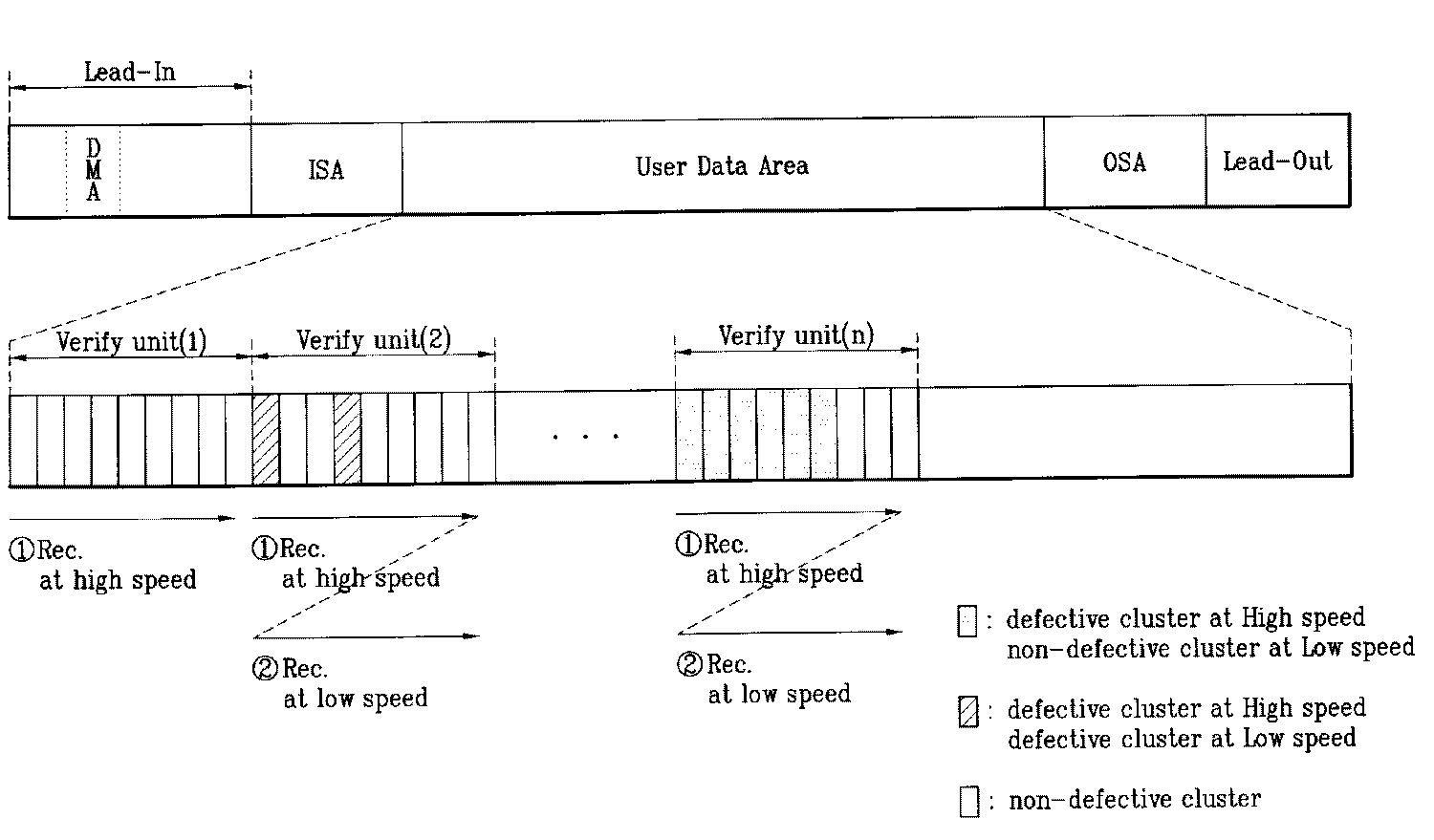
한편, 상기 BD-RE는 도 1에 도시한 바와 같이, 리드인 영역(Lead-In Area)과 데이터 영역(Data Area), 그리고 리드아웃 영역(Lead-Out Area)이 구분 할당됨과 아울러, 상기 데이터 영역의 선두 및 후단에는, 이너 스페어 영역(ISA: Inner Spare Area)과 아우터 스페어 영역(OSA: Outer Spare Area)이 구분 할당된다. In the BD-RE, as shown in FIG. 1, a lead-in area, a data area, and a lead-out area are separately allocated and the data is allocated. Inner and spare areas (ISA: Inner Spare Area) and outer spare areas (OSA: Outer Spare Area) are divided and allocated to the front and rear ends of the area.
BD-RE는 소정의 기록단위에 대응되는 클러스터(Cluster) 단위로 기록하게 되는 데, 재기록가능한 디스크의 특성상 특정영역에 데이터를 여러번 반복적으로 기록하는 것이 가능하며, 이때 도 1에 도시한 바와 같이, 데이터를 기록하던 도중, 상기 데이터 영역에 결함영역이 존재하는 지를 검출하게 된다. 그리고, 상기 결함영역이 검출되는 경우, 해당 결함영역에 기록될 데이터를, 상기 스페어 영역, 예를 들어 이너 스페어 영역(ISA)에 대체(replacement)기록하는 일련의 대체 기록동작을 수행함과 아울러, 상기 결함영역에 대한 위치정보(A,B address)와, 상기 스페어 영역에 대체기록된 위치정보(a,b address)를 관리정보로서 상기 리드인 영역내의 DMA에 결함리스트(DFL : Defect List)로 기록 저장하게 된다. The BD-RE is recorded in a cluster unit corresponding to a predetermined recording unit. Due to the characteristics of a rewritable disc, the BD-RE can repeatedly record data in a specific area several times. As shown in FIG. While recording data, it is detected whether a defective area exists in the data area. When the defective area is detected, a series of replacement recording operations are performed to replace data to be recorded in the defective area in the spare area, for example, an inner spare area ISA. Position information (A, B address) for the defective area and position information (a, b address) alternately recorded in the spare area are recorded in the DMA in the lead-in area as a defect list (DFL: Defect List) as management information. Will be saved.
한편, 최근에는 고배속(2배속이상) 기록가능한 BD-RE 및 고배속 기록가능한 BD-WO (Blu-ray disc write once)에 대한 규격화 작업이 논의되고 있는 바, 고배속 기록가능한 디스크는 1배속 기록가능한 디스크에 비해 디스크 회전속도뿐만아니라 최적기록파워 및 기록펄스등 많은 부분에 있어 차이가 있다 할 것이다.On the other hand, in recent years, standardization work on high-speed (over 2x) recordable BD-RE and high-speed recordable BD-WO (Blu-ray disc write once) has been discussed. Compared to the disk rotation speed, there are many differences in the optimum recording power and recording pulse.
또한, 일반적으로 고배속으로 기록시는 저배속(예를들어 1배속)으로 기록시보다 많은 결함영역이 발생되고 있으며, 이러한 결함영역은 전체 디스크의 성능을 떨어뜨리고 시스템에 부하로 존재하는 원인이 되고 있다.In general, when recording at a high speed, more defective areas are generated than when recording at a low speed (for example, 1x speed). Such defective areas reduce the performance of the entire disk and cause a load on the system. have.
따라서, 최근 논의중인 고배속 기록가능한 BD-RE 및 BD-WO의 경우는, 고배속에 대응하는 효율적인 결함영역 관리방안 마련이 절실히 요구된다 할 것이며, 특히 이는 규격화된 정보로서 제공되어야 상호간의 호환성을 확보할 수 있다 할것이다. Therefore, in the case of the high-speed recordable BD-RE and BD-WO, which are recently discussed, it is urgently required to prepare an effective defect area management plan corresponding to the high-speed, and in particular, it must be provided as standardized information to ensure mutual compatibility. I can do it.
본발명은 상기의 실정을 감안하여 창작된 것으로, 고배속에 대응하는 규격화된 정보로서 결함영역을 관리하는 새로운 방법을 제시하고자 하며, 특히 결함영역에 대한 정보를 효율적으로 기록 관리하고, 새로운 결함영역 관리방안을 통해 광디스크의 효율적인 기록재생을 수행하는 데 그 목적이 있는 바, 다음과 같은 특징적인 기술적 과제를 가지고 있다. The present invention was created in view of the above-mentioned situation, and is intended to suggest a new method of managing defect areas as standardized information corresponding to high speed, in particular, to efficiently record and manage information on defect areas, and to manage new defect areas. The purpose of the efficient recording and reproducing of the optical disc through the scheme is to provide the following technical problems.
기록배속에 대응하는 새로운 결함영역 관리방안을 제공하고자 하며, To provide a new management method for defect areas corresponding to recording speed,
디스크내의 관리영역에 규격화된 방법으로 결함영역 정보의 관리를 수행하므로서 동일계열의 디스크간의 상호 호환성을 제공하고자 하며,To manage the defect area information in a standardized way in the management area of the disk, to provide mutual compatibility between the disks of the same series,
또한 상기의 결함영역 관리방안을 이용하여 광디스크에 실제 데이터를 기록재생하는 기록재생방법 및 기록재생장치를 제공하고자 한다.Another object of the present invention is to provide a recording / playback method and a recording / playback apparatus for recording and reproducing actual data on an optical disc by using the defect area management method described above.
상기와 같은 기술적과제를 달성하기 위한 본 발명에 따른 결함영역 관리방법은, 고배속 기록이 가능한 디스크내에 결함영역 관리를 위한 결함관리영역을 구비한 광디스크에서,상기 고배속으로 기록을 수행하면서 결함영역의 발생유무를 확인하는 단계와, 상기 확인결과 고배속에서 결함영역이 발생되면, 저배속으로 기록배속을 변경하여 해당영역의 결함여부를 재확인하는 단계와, 상기 확인결과 고배속에서 결함영역이었으나 저배속에서는 결함영역이 아닌 것으로 판단된 영역에 대해서도 상기 결함관리영역에 해당영역의 위치정보를 기록하여 관리하는 것을 특징으로 하며,The defect area management method according to the present invention for achieving the above technical problem, in the optical disk having a defect management area for managing the defect area in the disk capable of high-speed recording, the generation of a defect area while performing the recording at the high speed Checking whether there is a defect area at a high speed, changing the recording speed to a low speed, and reconfirming whether or not the area is defective; and checking the defect area at a high speed but at a low speed. The location information of the corresponding area is recorded and managed in the defect management area even for the area judged not to be,
또한, 본 발명에 따른 결함영역 관리방법은, 고배속 기록이 가능한 디스크내에 결함영역 관리를 위한 결함관리영역을 구비하고 결함영역에 대한 위치정보를 결함리스트(Defect List)내에 엔트리(entry)로 기록하여 관리하는 광디스크에서, 상기 고배속에서 결함영역 이었으나 저배속에서는 결함영역이 아닌 것으로 판단된 영역의 위치정보를 제1엔트리에 기록하고, 상기 고배속과 저배속 모두에서 결함영역으로 판단된 영역의 위치정보를 제2엔트리에 기록하되, 제2엔트리와 제1엔트리를 서로 구별하는 식별정보를 엔트리내에 기록하여 관리하는 것을 특징으로 하며, In addition, the defect area management method according to the present invention includes a defect management area for managing a defect area in a disk capable of high-speed recording, and records position information on the defect area as an entry in a defect list. In the optical disk to be managed, the position information of the area which is a defective area at the high speed but is determined not to be the defective area at the low speed is recorded in the first entry, and the location information of the area determined as the defective area at both the high speed and the low speed is recorded. Recording in the second entry, wherein identification information distinguishing the second entry and the first entry from each other is recorded in the entry and managed;
또한, 본 발명에 따른 결함영역 관리방법은, 고배속 기록이 가능한 디스크내에 결함영역 관리를 위한 결함관리영역을 구비한 광디스크에서, 상기 허용가능한 최대배속으로 기록을 수행하면서 결함영역의 발생유무를 확인하는 제1단계와, 상기 확인결과 최대배속에서 결함영역이 발생되면, 최대배속보다 낮은 중간배속으로 적어도 1회이상 기록배속을 변경하여 해당영역의 결함여부를 재확인하는 제2단계와, 상기 확인결과 중간배속에서도 결함영역으로 판단되면, 최저배속으로 기록배속을 변경하여 해당영역의 결함여부를 재확인하는 제3단계와, 상기 각 단계별 확인결과에 따라 결함영역으로 판단된 영역에 대해 상기 결함관리영역에 해당영역의 위치정보를 기록하여 관리하는 것을 특징으로 하며,In addition, the defect area management method according to the present invention, in an optical disc having a defect management area for managing a defect area in a disk capable of high-speed recording, checks whether a defect area is generated while performing recording at the maximum allowable speed. A first step and, if the defective area is generated at the maximum speed as a result of the checking, a second step of changing the recording speed at least once or more at an intermediate speed lower than the maximum speed to reconfirm whether the area is defective or not; Also, if it is determined that the defective area is determined, the third step of re-checking whether or not the defective area is changed by changing the recording speed to the lowest speed, and corresponding area to the defect management area for the area determined to be defective area according to the result of each step check Characterized in that to record and manage the location information,
또한, 본 발명에 따른 광디스크는. 고배속 기록이 가능한 디스크로서 결함영역 관리를 위한 결함관리영역과 실제 데이터를 기록하는 데이터영역을 구비한 광디스크에서, 상기 고배속에서 결함영역이었으나 저배속에서는 결함영역이 아닌 것으로 판단된 데이터영역내의 위치정보를 기록하는 영역을 상기 결함관리 영역내에 구비한 것을 특징으로 하며,In addition, the optical disk according to the present invention. In an optical disk having a high speed recording disc having a defect management area for managing a defect area and a data area for recording actual data, location information in a data area that is determined to be a defective area at a high speed but not a defective area at a low speed is used. And an area for recording is provided in the defect management area.
또한, 본 발명에 따른 광디스크의 기록방법은, 고배속 기록이 가능한 디스크에 기록을 수행함에 있어서, 특정영역에 대한 기록명령을 수신하고, 상기 특정영역에 대해 고배속으로 기록을 수행하면서 결함영역의 발생유무를 확인하고, 상기 확인결과 고배속에서 결함영역이 발생되면, 저배속으로 기록배속을 변경하여 해당영역의 결함여부를 재확인하고, 상기 고배속 및 저배속 모두에서 결함영역으로 판단된 영역에 대해서는 해당영역에 기록될 데이터를 대체영역으로 대체기록하고, 상기 고배속에서 결함영역이었으나 저배속에서는 결함영역이 아닌 것으로 판단된 영역에 대해서는 해당영역에 저배속으로 기록을 수행하는 것을 특징으로 하며,In addition, in the recording method of the optical disc according to the present invention, when performing recording on a disc capable of high-speed recording, whether a defective area is generated while receiving a recording command for a specific area and recording at a high speed for the specific area. If a defective area is generated at a high speed, the recording speed is changed to a low speed to check whether there is a defect in the corresponding area, and for the area determined as a defective area at both the high speed and the low speed, It is characterized in that the data to be recorded is replaced with the replacement area, and recording is performed in the corresponding area at a low speed for an area determined to be a defective area at the high speed but not a defective area at the low speed.
또한, 본 발명에 따른 광디스크의 기록재생장치는, 특정영역에 대하여 기록수행을 요구하는 기록명령을 전달하는 제어부와, 상기 특정영역에 대해 고배속으로 기록을 수행하면서 결함영역의 발생유무를 확인하고, 상기 확인결과 고배속에서 결함영역이 발생되면, 저배속으로 기록배속을 변경하여 해당영역의 결함여부를 재확인하고, 상기 고배속 및 저배속 모두에서 결함영역으로 판단된 영역에 대해서는 해당영역에 기록될 데이터를 대체영역으로 대체기록하고, 상기 고배속에서 결함영역이었으나 저배속에서는 결함영역이 아닌 것으로 판단된 영역에 대해서는 해당영역에 저배속으로 기록을 수행하는 기록재생부로 구성된 것을 특징으로 한다. In addition, the recording / reproducing apparatus of the optical disc according to the present invention includes a control unit which transmits a recording command for requesting recording to a specific area, and confirms whether a defective area is generated while recording at a high speed for the specific area, As a result of the check, if a defective area is generated at a high speed, the recording speed is changed to a low speed to reconfirm whether the area is defective. And a recording / reproducing section which records recording in a substitute area, and writes in the corresponding area at a low speed for an area determined to be a defective area at a high speed but not a defective area at a low speed.
이하, 본 발명에 따른 고배속 기록가능한 광디스크에서의 결함영역 관리방법 및 기록방법과 기록재생장치를 첨부된 도면을 참조하여 상세히 설명하기로 한다.Hereinafter, a defect area management method, a recording method and a recording / reproducing apparatus in a high speed recordable optical disc according to the present invention will be described in detail with reference to the accompanying drawings.
우선 본발명에서 사용된 용어는 기존에 정의된 용어를 사용함을 원칙으로 하였으나, 새로운 기술의 출현에 따라 본발명에서 출원인이 가장 적합하다고 판단한 용어도 임의로 사용하였으며, 이에대해서는 해당 설명부에서 용어의 의미를 명확히 설명하였다. 따라서, 본발명을 이해함에 있어 단순한 용어로서가 아니라 해당 용어가 가지는 의미로 발명을 이해하여야 할 것임을 밝혀두고자 한다.First of all, the terminology used in the present invention is a term defined previously. However, in accordance with the emergence of a new technology, the terminology determined by the applicant is most appropriate in the present invention is arbitrarily used. Is clearly explained. Therefore, in the understanding of the present invention, it is intended to be understood that the invention should be understood in terms of the terms rather than mere terms.
또한 설명의 편의를 위해 고배속 기록가능한 디스크로서 BD계열의 디스크(Blu-ray Disc)를 예로들어 설명하고자 하나, 상기 BD디스크외에도 향후 개발되는 고밀도의 고배속 기록가능한 다른종류의 광디스크에도 동일하게 적용가능함 은 당연하다 할 것이다.In addition, for convenience of description, a high-speed recordable disc will be described using a BD-based disc as an example. It will be natural.
본발명은 고배속 기록가능한 광디스크에서의 새로운 결함영역 관리방안을 제시함을 특징으로 하는 바, 우선 본발명에서 사용한 "결함영역" 및 "결함영역 관리"의 의미에 대해 설명하고자 한다.The present invention is characterized by suggesting a new defect area management method in a high-speed recordable optical disc. First, the meanings of "defect area" and "defect area management" used in the present invention will be explained.
본발명에서 "결함영역(defective area)"이라 함은, 디스크내의 특정영역이 특정의 원인에 의해 향후 복구불가능한 영역 (uncorrectable area)으로 발전될 위험이 높은 영역을 의미하는 것으로, 현재 단계에서는 해당영역의 데이터가 충분히 보존되고 있는 영역을 의미하며, 상기 "결함영역을 관리한다" 함은, 해당데이터가 기록된 또는 기록될 특정영역이 복구불가능한 영역 (uncorrectable area)으로 되기전에 이를 결함영역으로 지정하고 디스크내의 대체영역으로 데이터를 이전하여 대체기록하므로서 디스크내에 기록된 데이터의 신뢰성을 더욱 높이는 관리방안을 의미한다. 특히 피씨(PC) 데이터와 같이 데이터 자체가 중요한 의미를 가지는 정보를 기록하거나 재생하는 경우에 결함영역의 관리가 더욱 필요하다 할 것이다. In the present invention, the term "defective area" refers to an area in which a particular area of a disk has a high risk of developing into an uncorrectable area in the future due to a specific cause. The term " manage defect area " means to designate a defective area before the specific area in which the data is recorded or to be recorded becomes an uncorrectable area. Means a management method to further improve the reliability of the data recorded in the disk by transferring data to the replacement area in the disk. In particular, in the case of recording or reproducing information in which data itself has an important meaning, such as PC data, management of a defective area will be more necessary.
따라서, 어떤경우에 "결함영역"으로 판단할 지에 대한 기준을 마련하는 것이 중요한 문제가 될 수 있으며, 이러한 기준은 시스템의 설계자가 설계하는 시스템의 부하를 줄이기 위해 다소 높은 기준을 적용하여 "결함영역"의 발생을 작게 할 수도 있으며(잦은 대체기록을 방지하기 위해), 반대로 데이터의 신뢰성을 더욱 보장하기위해 다소 낮은 기준을 적용하여 "결함영역"을 많이 지정하고 대체영역으로 데이터를 안정하게 대체할 수도 있다 할 것이다.Therefore, it may be an important issue to establish a criterion for what to consider as a "fault area", and this criterion is applied to a "fault area" by applying rather high standards to reduce the load on the system designed by the designer of the system. "In order to reduce the occurrence of" (to prevent frequent replacement records), on the contrary, in order to ensure the reliability of the data, it is possible to designate a lot of "fault areas" and to replace the data stably with the replacement areas. You may have to.
상기 결함영역으로 판단하는 기준은 여러 규격화된 디스크에서 서로 상이한 기준을 제시하고 있으며, 대체적으로는 기록단위내에 발생되는 에러(error)량을 기준으로 하는 것이 일반적이다. 예를들면, 특정 갯수이상의 에러가 발생되면 "결함영역"으로 판정하여 데이터를 대체영역에 대체기록하고, 특정 갯수이상의 에러가 발생되지 않으면 "결함영역"으로 판정하지 않고 시스템내의 에러정정코드(ECC: Error correction code)등을 이용하여 에러를 정정하게 된다. 따라서 시스템설계자는 최적의 시스템 및 데이터보호를 고려하여 상기 시스템내에서 적용할 "기록단위내 특정갯수의 에러량"에 대한 기준을 정의해 두므로서, 해당 기록단위를 결함영역으로 판단할지 아니면 정상영역으로 판단할지를 결정할 수 있게 되는 것이다. The criterion for determining the defective area is different from each other in various standardized discs, and it is generally based on the amount of errors occurring in the recording unit. For example, if more than a certain number of errors occur, it is determined as a "fault area" and data is written to the replacement area. If no error is more than a certain number, an error correction code (ECC) in the system is not determined as a "fault area". Error correction code is used to correct the error. Therefore, the system designer defines the criteria for the "a certain number of errors in the recording unit" to be applied in the system in consideration of the optimal system and data protection. It is possible to decide whether to judge the area.
따라서, 본발명에서는 결함영역을 판단함에 있어, 상기와 같은 방식의 결함영역 판단방법(예를들어, "기록단위내 특정갯수의 에러량"이 얼마인가?)을 적용하면서도, 추가적으로 기록배속에 대응하는 결함영역 판단방법을 새로이 제시하고자 하며, 이는 기록배속의 차이에 따라 기록단위내에 발생되는 에러량등에 차이가 있어 "결함영역"으로의 판정에 영향을 미치기 때문이다. 일반적으로 고배속으로 기록시 더욱 많은 "결함영역"이 발생하는 이유도 고배속시는 전체적인 시스템이 불안정해지므로 기록단위내에 발생되는 에러량이 저배속에 비해 증가하기 때문이다. Accordingly, in the present invention, in determining the defective area, the above-described method for determining the defective area (for example, "what is the amount of error of a certain number in the recording unit?") Is applied, but additionally corresponds to the recording speed. The present invention proposes a new method for determining a defective area, because the amount of errors occurring in the recording unit varies depending on the recording speed, which affects the determination of the defect area. In general, more "defective areas" occur when recording at high speed, because the entire system becomes unstable at high speed, and the amount of error generated in the recording unit increases compared to low speed.
도2,3은 본발명의 기록배속에 대응하는 결함영역 관리방법을 개념적으로 설명하기 위한 광디스크구조 및 흐름도를 간략히 도시한 것이다. 2 and 3 briefly illustrate an optical disc structure and a flowchart for conceptually explaining a defect area management method corresponding to the recording speed of the present invention.
도2는 본발명 광디스크에서의 기록수행시 흐름을 도시한 것으로, 디스크의 데이터 영역내에 기록을 수행함에 있어 우선 허용가능한 고배속으로 특정구간만큼을 기록하고 동구간에서 결함영역의 발생여부를 확인하게 된다. 예를들어 상기 특 정구간을 검증단위(Verify unit)로 명하고 도2에서와 같이 약 9개의 기록단위별로 하나의 검증단위를 형성하도록 하였다. 하지만 상기 9개의 기록단위수는 설명의 편의를 위해 설정한 것으로, 얼마든지 다른설정이 가능함은 자명하다 할 것이다. Fig. 2 shows the flow of recording in the optical disc of the present invention. In performing recording in the data area of the disc, first, as much as an allowable high speed is recorded, a specific section is recorded, and whether or not a defective area is generated in the same section. . For example, the specific section is designated as a verification unit, and as shown in FIG. 2, one verification unit is formed for each of nine recording units. However, the number of nine recording units is set for convenience of explanation, and it will be obvious that other settings can be made.
도2의 검증단위(1)과 같이 해당 고배속에서 결함영역이 발생되지 않으면, 다음 검증단위(2)에서 상기 과정을 반복하게 되고, 만약 검증단위(2)에서 결함영역이 발생하였다면 저배속으로 기록배속을 낮추어 결함영역의 발생여부를 다시한번 확인하게 된다. 이때 기록배속을 낮추어 기록하는 경우에도 해당영역이 결함영역으로 판단된다면, 상기 영역은 스페어영역으로 대체기록을 수행하는 기존의 결함영역으로 판단하고 결함영역 관리를 수행한다.If a defective area does not occur at the corresponding high speed as in the verification unit (1) of FIG. 2, the process is repeated in the next verification unit (2), and if the defective area occurs in the verification unit (2), the recording is performed at a low speed. By lowering the speed, it is once again confirmed whether or not a defect area has occurred. If the corresponding area is determined to be a defective area even when recording at a lower recording speed, the area is determined to be an existing defective area for performing replacement recording as a spare area and defect management is performed.
그러나, 검증단위(n)와 같이 고배속에서는 결함영역으로 판단되었으나, 저배속에서는 결함영역이 아닌것으로 판단된 영역은 스페어영역으로 대체하지 않고 해당영역에 결함이 발생되지 않는 저배속으로 기록을 수행하되, 해당영역의 위치정보와 배속정보를 결함관리영역(DMA)내에 기록하여 관리하도록 하였다.However, as in the verification unit (n), the area determined to be a defective area at a high speed, but not determined to be a defective area at a low speed, is replaced with a spare area and the recording is performed at a low speed at which a defect does not occur in the corresponding area. In addition, location information and speed information of the corresponding area are recorded in the defect management area (DMA) for management.
따라서, 기록배속의 변화에 따라 결함영역이 아닌것으로 판단되는 영역은 정상영역으로 취급하되, 결함영역이 아니라고 판단되는 해당 기록배속정보를 함께 관리하므로서, 향후 동영역은 해당 기록배속으로 기록하는 것이 가능해짐에 따라, 데이터의 신뢰성을 유지할 수 있을뿐만 아니라, 대체기록에 따른 시스템의 부하도 줄일수 있게 되는 장점이 있게 된다.Therefore, the area judged to be not a defective area according to the change of the recording speed is treated as a normal area, but by managing the corresponding recording speed information determined to be not a defective area, the same area can be recorded at the corresponding recording speed in the future. As a result, not only data reliability can be maintained but also the load of the system due to the alternative recording can be reduced.
상기에서 결함영역을 검증하는 방법은 다양한 방식이 적용될 수 있으며, 일반적으로 데이터의 신뢰성 보장이 중요한 경우에는 "기록후 검증방식 (Verify after write)"이 적용되나, 이또한 시스템의 선택적 사항으로서 다양한 검증방식이 본발명에 적용가능함은 당연하다 할 것이다.The method of verifying a defective area may be applied in various ways. In general, when verifying the reliability of data is important, “Verify after write” is applied, but this is also an optional matter of the system. Naturally, the method is applicable to the present invention.
도3은 본발명의 기술적사상을 간략히 도시한 흐름도로서, 도2에서 설명한 바와 같이, 고배속으로 기록을 수행하다 결함영역을 만나면 저배속으로 기록배속을 낮추어 해당영역의 결함유무를 재확인하고, 저배속에서도 결함영역으로 판단되면 결함관리영역내의 결함리스트(DFL)에 정상적인 대체기록을 의미하는 정보로서 결함정보를 기록하고(RAD type : Re-Allocatable-Defect), 만약 저배속에서는 결함영역으로 판단되지 않는다면 대체기록은 수행하지 않되, 결함관리영역내의 결함리스트(DFL)에 상기 정상 대체된 결함정보와 서로 구별되는 종류로서 결함정보를 기록해둔다(NDR type : Non-Defctive at low Recording speed).3 is a flowchart briefly illustrating the technical concept of the present invention. As described with reference to FIG. 2, when recording is performed at a high speed, when a defect area is encountered, the recording speed is lowered at a low speed to reconfirm the presence or absence of a defect in the corresponding area. If it is determined to be a defective area, the defect information is recorded in the defect list (DFL) in the defect management area as information indicating normal replacement recording (RAD type: Re-Allocatable-Defect). The alternative recording is not performed, but the defect information is recorded in the defect list (DFL) in the defect management area as a type distinguished from the normal replaced defect information (NDR type: Non-Defctive at low Recording speed).
이하 도4부터 도12까지를 참조하여, 상기 본발명의 기술적사상을 뒷받침하는 구체적인 결함영역 관리방법 및 결함정보 기록방법 등에 대해 상세히 설명하기로 한다.4 to 12, a detailed defect area management method and a defect information recording method supporting the technical concept of the present invention will be described in detail.
우선 결함관리영역내에 결함영역의 위치정보를 결함리스트(DFL)로 기록하는 일반적인 방법에 대해 설명하면, DFL은 리스트로 구성되어 있고 리스트내는 결함영역의 위치정보를 8바이트의 엔트리(entry)로 기록한 복수의 엔트리로 구성된다. 하나의 엔트리는 결함영역의 종류를 식별하는 식별정보를 기록하는 필드(status1, status2)가 있고, 또한 일반적으로 데이터영역내 결함영역으로 판단된 위치를 기록하는 "Defective cluster first PSN"필드와, 상기 결함영역이 대체되는 영역의 위치를 기록하는 "Replacement cluster first PSN"필드가 있다. 그러나, 상기 필드명 은 기존의 BD-RE와의 호환성을 위해 동일한 필드명칭을 사용한 것일뿐 해당 필드에 기록되는 내용은 상기 일반적인 경우와 상이할 수 있으며, 이하 본발명의 실시예를 통해 상세히 설명하기로 한다.First, the general method of recording the position information of the defect area in the defect management area as a defect list (DFL) will be described. The DFL is composed of a list and records the position information of the defect area in the list as an entry of 8 bytes. It consists of a plurality of entries. One entry includes fields (status1 and status2) for recording identification information for identifying the type of defective area, and generally includes a "Defective cluster first PSN" field for recording a position determined as a defective area in the data area, and There is a "Replacement cluster first PSN" field that records the location of the area where the defective area is to be replaced. However, the field name is used only for the same field name for compatibility with the existing BD-RE, the content recorded in the field may be different from the general case, and will be described in detail through embodiments of the present invention below. do.
도4,5는 본발명에 따른 결함영역의 위치정보를 기록하여 관리하는 제1실시예에 관한 것으로, 결함영역에 대한 위치정보를 최소기록단위인 클러스터마다 기록하는 것을 특징으로 한다. 4 and 5 relate to a first embodiment in which the location information of the defective area according to the present invention is recorded and managed, and the location information of the defective area is recorded for each cluster which is the minimum recording unit.
도4의 데이터영역내에는 2가지 종류의 결함영역이 존재하며, 하나는 고배속 및 저배속 모두에서 결함영역으로 판단된 경우이고(A,B), 또다른 하나는 고배속에서는 결함영역으로 판단되었으나, 저배속에서는 결함영역이 아닌것으로 판단되는 경우이다(C,D). There are two kinds of defect areas in the data area of FIG. 4, one of which is determined to be a defective area at both high and low speeds (A, B), and the other is determined to be a defective area at high speeds. At low speed, it is judged that it is not a defective area (C, D).
따라서, 상기 A,B 클러스터에 기록될 데이터는 스페어영역내의 a,b 영역으로 대체되어 기록되고, 이에대한 결함영역의 정보는 정상적으로 대체되었음을 지정하는 RAD(Re-Allocatable-Defect)타입의 엔트리로서 status1=0000로 기록되고, "Defective cluster first PSN"필드에는 A,B영역의 위치정보를, "Replacement cluster first PSN"필드에는 이에 대응하는 a,b영역의 위치정보를 각각 기록하여 관리하게 된다.Therefore, the data to be recorded in the clusters A and B is replaced by the a and b areas in the spare area and recorded, and the status1 is an RAD (Re-Allocatable-Defect) type entry indicating that the information on the defective area is normally replaced. It is recorded as = 0000, and the location information of areas A and B is recorded in the "Defective cluster first PSN" field, and the location information of areas a and b corresponding thereto is recorded and managed in the "Replacement cluster first PSN" field.
그러나, C,D영역은 고배속에서만 결함영역으로 판단되고, 저배속에는 정상영역으로 판단되어 대체기록되지 않은 영역이므로, 상기 A,B영역과는 결함정보의 기록방법을 달리하는 것이 필요하며, 따라서 status1=1001을 부여하여 NDR (Non-Defctive at low Recording speed) 타입으로 정의하고 , "Defective cluster first PSN"필드에는 C,D영역의 위치정보를 기록하고, "Replacement cluster first PSN"필드에는 대체되는 영역이 없으므로 정상영역으로 판단된 경우의 기록배속정보 (Recording speed info)를 기록해둔다. 따라서 다음번에 해당 광디스크가 재차 로딩되었을때 기록재생부(도12, 10)는 해당 관리정보를 참조하여 C,D영역에의 기록은 결함영역이 발생되지 않도록 해당 엔트리에 기록된 기록배속정보를 참조하여 기록하므로서 결함영역이 발생될 확률을 더욱 줄일 수 있게 된다. "Replacement cluster first PSN"필드에 기록되는 기록배속정보로서 상기와 달리 결함영역이 발생한 고배속정보를 기록해두는 것도 가능하다. 이는 시스템이 마찬가지로 해당영역은 엔트리에 기록된 배속으로 기록시 결함영역이 발생하였다는 것을 알 수 있으므로 그보다 낮은 배속을 적용하여 기록하는 것이 가능하기 때문이다.However, since the C and D areas are judged to be defective areas only at high speeds and are not recorded as replacement areas at low speeds, it is necessary to change the defect information recording method from the A and B areas. Defined as NDR (Non-Defctive at low Recording speed) type by giving status1 = 1001, record location information of C, D area in "Defective cluster first PSN" field, and replace in "Replacement cluster first PSN" field. Since there is no area, recording speed info is recorded when it is determined to be a normal area. Therefore, the next time the optical disc is loaded again, the recording / reproducing section (Figs. 12 and 10) refers to the management information and records the recording speed information recorded in the corresponding entry so that a defective area does not occur in the recording in the C and D areas. By recording the data, the probability of generating a defective area can be further reduced. As the recording speed information recorded in the "Replacement cluster first PSN" field, it is also possible to record the high speed information at which the defective area is generated unlike the above. This is because the system is able to record by applying a lower speed than that because the system can know that a defective area has occurred during recording at the speed recorded in the entry.
도5는 도4의 경우에 결함정보로서 엔트리를 구별하는 테이블이다. 즉 status1=0000 이면, 정상적으로 대체된 결함영역을 의미하고 (RAD entry), status1=1001 이면, 고배속에서는 결함영역으로 판단되고 저배속에서는 결함영역이 아닌 영역임을 의미하고 (NDR entry), 해당 NDR entry내에는 결함영역이 아니라고 판단된 경우의 기록배속정보(Recording speed info), 즉 저배속에 대한 정보를 기록해둠을 의미한다. FIG. 5 is a table for distinguishing entries as defect information in the case of FIG. That is, if status1 = 0000, it means a defective area that is normally replaced (RAD entry), and if status1 = 1001, it means that the area is determined to be a defective area at high speed and not a defective area at low speed (NDR entry), and the corresponding NDR entry. This means that recording speed info, that is, low speed information, is recorded when it is determined that it is not a defective area.
도6,7은 본발명에 따른 결함영역의 위치정보를 기록하여 관리하는 제2실시예에 관한 것으로, 결함영역에 대한 위치정보를 연속하는 최소기록단위인 클러스터마다 기록하는 것을 특징으로 한다. 6 and 7 relate to a second embodiment of recording and managing position information of a defective area according to the present invention, wherein the position information of the defective area is recorded for each cluster which is a continuous minimum recording unit.
도6의 데이터영역내에는 2가지 종류의 결함영역이 존재하며, 하나는 고배속 및 저배속 모두에서 결함영역으로 판단된 경우이고(A,B), 또다른 하나는 고배속에서는 결함영역으로 판단되었으나, 저배속에서는 결함영역이 아닌것으로 판단되는 경우이다(C,D). There are two kinds of defect areas in the data area of FIG. 6, one of which is determined as a defective area at both high and low speeds (A, B), and the other is determined as a defective area at high speeds. At low speed, it is judged that it is not a defective area (C, D).
따라서, 상기 A,B 클러스터에 기록될 데이터는 스페어영역내의 a,b 영역으로 대체되어 기록되고, 이에대한 결함영역의 정보는 정상적으로 대체되었음을 지정하는 RAD타입(status1=0000)의 엔트리로서 "Defective cluster first PSN"필드에는 A,B영역의 위치정보를, "Replacement cluster first PSN"필드에는 이에 대응하는 a,b영역의 위치정보를 각각 기록하여 관리하게 된다.Therefore, the data to be recorded in the A and B clusters are replaced by the a and b areas in the spare area and recorded, and the defective area information is an entry of the RAD type (status1 = 0000) that specifies that the information is normally replaced. The location information of areas A and B is recorded in the "first PSN" field, and the location information of areas a and b corresponding thereto is recorded and managed in the "Replacement cluster first PSN" field.
그러나, C,D영역은 고배속에서만 결함영역으로 판단되고, 저배속에는 정상영역으로 판단되어 대체기록되지 않은 영역이므로, 상기 A,B영역과는 결함정보의 기록방법을 달리하는 것이 필요하며, 또한 C영역은 이후 연속적인 복수개의 클러스터가 동일영역으로 판단된 경우이고, D영역은 하나의 클러스터만이 해당하는 영역임을 알수 있다. 따라서 status1=1001을 부여하여 NDR (Non-Defctive at low Recording speed) 타입임을 표시하되, status2 필드에는 해당하는 영역의 연속적인 기록단위의 갯수를 바이너리값으로 표시하는 것으로 정의하였다. 예를들어, 도6과 같이 C영역은 이후 4개의 클러스터가 연속되므로 status2=0100으로 기록하고, D영역은 단독의 클러스터이므로 status2=0001로 기록하면 된다. 나머지 필드는 제1실시예와 마찬가지로 "Defective cluster first PSN"필드에는 연속되는 기록단위중 시작클러스터인 C,D영역의 위치정보를 기록하고, "Replacement cluster first PSN"필드에는 대체되는 영역이 없으므로 정상영역으로 판단된 경우의 기록배속정보 (Recording speed info)를 기록해둔다. 따라서 다음번에 해당 광디스크가 재차 로딩되었을때 기록재생부(도12, 10)는 C,D영역의 기록시는, 결함관리정보내의 크기정보 (size info)에 표시된 연속되는 클러스터까지 결함영역이 발생되지 않도록 해당 엔트리에 기록된 기록배속정보를 참조하여 기록하므로서 결함영역이 발생될 확률을 더욱 줄일 수 있게 된다. 또한 "Replacement cluster first PSN"필드에 기록되는 기록배속정보로서 상기와 달리 결함영역이 발생한 경우의 고배속정보를 기록해두는 것도 가능하며, 이경우 시스템은 해당영역이 엔트리에 기록된 배속으로 기록시 결함영역이 발생하였다는 것을 알 수 있으므로 그보다 낮은 배속을 적용하여 기록하는 것이 가능하기 때문이다.However, since the C and D areas are determined to be defective areas only at high speeds, and are not recorded as replacement areas at low speeds, it is necessary to change the defect information recording method from the A and B areas. Area C is a case where successive plural clusters are determined to be the same area, and it can be seen that area D corresponds to only one cluster. Therefore, it is designated as NDR (Non-Defctive at low Recording speed) type by giving status1 = 1001, and the status2 field is defined as displaying the number of consecutive recording units in the corresponding area as a binary value. For example, as shown in Fig. 6, since the four clusters are continuous in the C region, the
도6은 도5의 경우에 결함정보로서 엔트리를 구별하는 테이블이다. 즉 status1=0000 이면, 정상적으로 대체된 결함영역을 의미하고 (RAD entry), status1=1001 이면, 고배속에서는 결함영역으로 판단되고 저배속에서는 결함영역이 아닌 영역임을 의미하고 (NDR entry), 해당 NDR entry내에는 연속되는 클러스터의 크기정보(size info)를 status2필드에 기록하고, 결함영역이 아니라고 판단된 경우의 기록배속정보(Recording speed info), 즉 저배속에 대한 정보를 "Replacement cluster first PSN"필드에 기록해둠을 의미한다. FIG. 6 is a table for distinguishing entries as defect information in the case of FIG. That is, if status1 = 0000, it means a defective area that is normally replaced (RAD entry), and if status1 = 1001, it means that the area is determined to be a defective area at high speed and not a defective area at low speed (NDR entry), and the corresponding NDR entry. The size information of successive clusters is recorded in the status2 field, and recording speed info when it is determined that it is not a defective area, that is, information about low speed, is stored in the "Replacement cluster first PSN" field. It means to write in
상기 제2실시예는 제1실시예에 비해 엔트리의 갯수를 줄일수 있는 효과가 있다 할것이다.The second embodiment will have the effect of reducing the number of entries compared to the first embodiment.
도8,9는 본발명에 따른 결함영역의 위치정보를 기록하여 관리하는 제3실시예에 관한 것으로, 고배속에서만 결함영역으로 판단되고 저배속에서는 결함영역이 아 닌것으로 판단된 영역의 위치정보를 구간으로 지정하여 기록하는 것을 특징으로 한다. 8 and 9 relate to a third embodiment which records and manages position information of a defect area according to the present invention, wherein the position information of the area determined to be a defect area only at a high speed and not a defect area at a low speed is shown. It is characterized in that the recording by specifying the interval.
도8의 데이터영역내에는 2가지 종류의 결함영역 구간이 존재하며, 하나는 고배속 및 저배속 모두에서 결함영역으로 판단된 구간이고 (A~C 구간, verify unit(k)), 또다른 하나는 고배속에서는 결함영역으로 판단되었으나, 저배속에서는 결함영역이 아닌것으로 판단되는 구간이다(E~F구간,verify unit(n)). There are two kinds of defective area sections in the data area of FIG. 8, one is a section determined as a defective area at both high and low speeds (A-C section, verify unit (k)), and another one. At high speeds, it was determined to be a defect area, but at low speeds, it was determined not to be a defect area (section E to F, verify unit (n)).
먼저, A~C구간은 고배속시 결함영역으로 판단되어 저배속으로 재차 검증한 결과, A,B,C영역은 마찬가지로 결함영역으로 판단되었고, D영역은 저배속에서는 결함영역이 아닌 것으로 판단된 경우로서 이경우 해당구간은 개별 클러스터별로 별도로 결함정보를 결함관리영역에 기록하게 된다. First, when sections A to C are judged to be defective areas at high speeds, and verified again at low speeds, areas A, B, and C are judged to be defective areas as well, and D areas are not determined to be defective areas at low speeds. In this case, the relevant section records defect information separately for each cluster in the defect management area.
그러나 E~F구간은 고배속시 결함영역으로 판단되어 저배속으로 재차 검증한 결과, 모든 클러스터가 저배속에서는 결함영역이 아니라고 판단된 경우로서, 해당구간은 전체구간(E에서 F까지)을 하나의 결함정보로서 기록하게 된다.However, when E ~ F section is judged to be a defective area at high speed and verified again at low speed, it is judged that all clusters are not a defective area at low speed, and the corresponding section is the entire section (E to F). It is recorded as defect information.
따라서, 상기 A,B,C클러스터에 기록될 데이터는 스페어영역내의 a,b,c 영역으로 대체되어 기록되고, 이에대한 결함영역의 정보는 정상적으로 대체되었음을 지정하는 RAD타입(status1=0000)의 엔트리로서 "Defective cluster first PSN"필드에는 A,B,C영역의 위치정보를, "Replacement cluster first PSN"필드에는 이에 대응하는 a,b,c영역의 위치정보를 각각 기록하여 관리하게 된다.Therefore, the data to be recorded in the A, B, and C clusters is replaced by the a, b, and c areas in the spare area, and the RAD type (status1 = 0000) entry indicating that the defective area information is normally replaced. In the "Defective cluster first PSN" field, location information of areas A, B, and C is recorded, and in the "Replacement cluster first PSN" field, location information of corresponding areas a, b, and c is recorded and managed.
또한, A~C구간내의 D영역은 고배속에서만 결함영역으로 판단되고, 저배속에는 정상영역으로 판단되어 대체기록되지 않은 영역이므로, 상기 A,B,C영역과는 결 함정보의 기록방법을 달리하는 것이 필요하며, 따라서 status1=1001을 부여하여 NDR타입임을 표시하되, status2=0000로 하여 해당하는 영역이 하나의 클러스터로서 하나의 엔트리로 기록된 것임을 알려준다. In addition, since the area D in the sections A to C is determined to be a defective area only at a high speed, and is a normal area at low speed, it is not replaced and recorded, and thus, the method of recording defect information differs from the areas A, B, and C. Therefore, it is indicated that it is NDR type by giving status1 = 1001, but status2 = 0000 indicates that the corresponding area is recorded as one entry as one cluster.
그러나, E~F구간은 이를 표현하기 위해 2개의 엔트리가 쌍으로 필요하며(pair entry), 첫번째 엔트리내에는 status2=0001로서 2개의 엔트리중 첫번째임을 알수 있게 하고, "Defective cluster first PSN"필드와 "Replacement cluster first PSN"필드에는 각각 동구간의 시작과 종료클러스터를 의미하는 E,F영역의 위치정보를 기록하고, 두번째 엔트리내에는 status2=0010 으로 2개의 엔트리중 두번째임을 알수 있게 하고, "Defective cluster first PSN"필드와 "Replacement cluster first PSN"필드에는 결함영역이 발생하지 않은 저배속에 대한 기록배속정보(Recording speed info)를 반복하여 기록해 둔다. 그러나 두번째 엔트리의 "Replacement cluster first PSN"필드에는 기록배속정보(Recording speed info)를 반복하여 기록하지 않고 "00h"로 셋팅하여도 무방하다 할 것이다.However, sections E through F require two entries in pairs to represent this, and in the first entry, status2 = 0001 indicates that it is the first of the two entries, and the field "Defective cluster first PSN" In the "Replacement cluster first PSN" field, record the location information of the E and F areas, which mean the start and end clusters of the same section, respectively. In the "first PSN" field and the "Replacement cluster first PSN" field, the recording speed info for the low speed in which no defect area is generated is repeatedly recorded. However, in the "Replacement cluster first PSN" field of the second entry, the recording speed info may be set to "00h" without repeatedly recording the recording speed info.
두번째 엔트리의 "Defective cluster first PSN"필드에 기록되는 기록배속정보로서 상기와 달리 결함영역이 발생한 경우의 고배속정보를 기록해두는 것도 가능하며, 이경우 시스템은 해당구간이 엔트리에 기록된 배속으로 기록시 결함영역이 발생하였다는 것을 알 수 있으므로 그보다 낮은 배속을 적용하여 기록하는 것이 가능하기 때문이다. As the recording speed information recorded in the "Defective cluster first PSN" field of the second entry, unlike the above, it is also possible to record the high speed information when a defect area occurs.In this case, the system will record a defect at the recording speed at the speed recorded in the entry. This is because it is possible to know that an area has occurred, so that it is possible to record at a lower speed.
도9는 도8의 경우에 결함정보로서 엔트리를 구별하는 테이블이다. 즉 status1=0000 이면, 정상적으로 대체된 결함영역을 의미하고 (RAD entry), status1=1001 이면, 고배속에서는 결함영역으로 판단되고 저배속에서는 결함영역이 아닌 영역임을 의미하나 (NDR entry), status2=0000 이면 클러스터별로 대응한 하나의 엔트리임을 의미하고, status2=0001 이면 특정구간을 표현하는 2개의 엔트리중 첫번째 엔트리를, status2=0010 이면 특정구간을 표현하는 2개의 엔트리중 두번째 엔트리를 의미하는 것으로 정의하는 것이다.FIG. 9 is a table for distinguishing entries as defect information in the case of FIG. That is, if status1 = 0000, it means a defective area that is normally replaced (RAD entry) .If status1 = 1001, it means that the area is determined to be a defective area at high speed and not a defective area at low speed (NDR entry), status2 = 0000 Is defined as one entry corresponding to each cluster, and status2 = 0001 is defined as the first entry of two entries representing a specific section, and status2 = 0010 is defined as meaning the second entry of two entries representing a specific section. will be.
상기 제3실시예는 구간별로 대응이 가능하여 시스템이 기록배속을 클러스터별로 변경하는 것에 비해, 부하를 저감할 수 있는 효과가 있다 할것이다.According to the third embodiment, it is possible to correspond to each section, so that the system can reduce the load compared to changing the recording speed by cluster.
도10은 결함관리영역내의 DFL의 구조를 간략히 도시한 것으로, 특히 DFL의 헤더(Header)내에는 해당 DFL에 기록된 결함정보(defect entry)중에 특정 타입의 엔트리가 몇개나 존재하는지를 알려주는 정보를 포함하고 있는 것을 특징으로 한다. 따라서, RAD-엔트리와, NDR-엔트리의 갯수를 헤더정보내에 기록해둠으로서, 시스템이 먼저 DFL헤더정보로 부터 손쉽게 엔트리의 갯수를 파악하는 것이 가능해 진다.Fig. 10 is a simplified diagram of the structure of the DFL in the defect management area. In particular, information indicating how many entries of a particular type exist among defect information recorded in the DFL in the header of the DFL is shown. It is characterized by including. Therefore, by recording the number of RAD entries and NDR entries in the header information, the system can easily determine the number of entries from the DFL header information first.
도11은 본발명의 기록배속에 대응하는 결함영역 관리방법을 설명하기 위한 또다른 흐름도이며, 도3의 개념적 흐름도를 확장한 실시예를 제시한 것이다.FIG. 11 is another flowchart for explaining a defect area management method corresponding to recording speed of the present invention, and shows an embodiment in which the conceptual flowchart of FIG. 3 is expanded.
기록명령을 수신한 기록재생부(도12, 10)는 디스크가 허용하는 최대배속(Vmax)으로 기록을 시작하고 기록수행도중 결함영역이 발생하지 않으면 계속 Vmax로 기록을 수행하고, 결함영역을 확인하면 최대배속보다 낮은 배속(Vnext)로 해당영역의 결함여부를 재확인한다.(step1)Receiving the recording command, the recording and reproducing section (Fig. 12, 10) starts recording at the maximum speed (Vmax) allowed by the disc. If no defective area occurs during recording, the recording and reproducing section continues to record at Vmax and checks the defective area. If it is lower than the maximum speed (Vnext), check whether there is any defect in the area.
Vnext로 기록시 해당영역이 결함영역이 아니라고 판단되면, 상기 도4,6,8의 제1,2,3실시예와 같은 방법을 이용하여 해당영역의 위치정보와 Vnext에서 결함영역이 아니라는 기록배속정보를 DFL에 등록하게 된다. 이때 제1,2,3 실시예에서 설명한 바와 같이 DFL에 등록하는 기록배속정보는 Vnext가 아니고 Vmax로 등록하여도 무방하다. Vnext로 기록시에도 Vmax로 기록시와 마찬가지로 해당영역이 결함영역이라고 판단되면, 디스크가 허용하는 1배속에 해당하는 Vnom으로 해당영역의 결함여부를 재확인한다.(step2)If it is determined that the area is not a defective area when recording with Vnext, recording speed is determined that the area is not a defective area in the location information and Vnext using the same method as in the first, second, and third embodiments of FIGS. 4, 6, and 8. The information will be registered in the DFL. At this time, as described in the first, second and third embodiments, the recording speed information registered in the DFL may be registered as Vmax instead of Vnext. When recording with Vnext, if it is determined that the corresponding area is a defective area as with recording with Vmax, check whether the corresponding area is defective at Vnom corresponding to the 1x speed allowed by the disc (step 2).
이때, 시스템에 따라서는 상기 단계(step2)에서 Vnext에 해당하는 배속을 복수로 설정하는 것도 가능하며, 예를들면, Vmax=16배속, Vnext1=8배속, Vnext2=4배속, Vnext3=2배속 과 같이 설정하여 최종 Vnom=1배속으로 검증하기 전에 상기 단계(step2)를 여러번 되풀이하는 것도 가능하다 할 것이다.At this time, depending on the system, it is also possible to set a plurality of double speeds corresponding to Vnext in the step (step2). For example, Vmax = 16 times, Vnext1 = 8 times, Vnext2 = 4 times, Vnext3 = 2 times and It may be possible to repeat the above step (step 2) several times before setting and verifying at the final Vnom = 1 times.
최종적으로, Vnom으로 기록시 해당영역이 결함영역이 아니라고 판단되면, 상기 도4,6,8의 제1,2,3실시예와 같은 방법을 이용하여 해당영역의 위치정보와 Vnom에서 결함영역이 아니라는 기록배속정보를 DFL에 등록하게 된다. 이때 제1,2,3 실시예에서 설명한 바와 같이 DFL에 등록하는 기록배속정보는 Vnom이 아니고 Vnext로 등록하여도 무방하다. Vnom으로 기록시에도 Vmax, Vnext로 기록시와 마찬가지로 해당영역이 결함영역이라고 판단되면, 해당영역의 데이터를 대체영역으로 이전하여 대체기록하고, 결함영역의 위치정보와 대체영역의 위치정보를 DFL에 등록하게 된다.(step3)Finally, if it is determined that the corresponding area is not a defective area when recording with Vnom, the defective area is determined from the position information of the corresponding area and Vnom using the same method as in the first, second, and third embodiments of FIGS. 4, 6, and 8. No registers the recording speed information in the DFL. At this time, as described in the first, second, and third embodiments, the recording speed information registered in the DFL may be registered as Vnext instead of Vnom. Similarly to recording with Vmax and Vnext, when recording with Vnom, if it is determined that the relevant area is a defective area, the data of the corresponding area is transferred to the replacement area for replacement recording, and the location information of the defective area and the location information of the replacement area are transferred to the DFL. Register (step3)
도12는 본발명이 적용되는 광디스크에서의 기록재생장치에 관한 것으로, 기록재생장치는 광디스크에 기록재생을 수행하는 기록재생부(10)와 이를 제어하는 제어부(20)로 구성된다. 제어부는 기록재생부로 특정영역에의 기록 또는 재생 명령을 내리고, 기록재생부는 제어부의 명령에 따라 특정영역에의 기록재생을 수행하게 된다. 기록재생부(10)는 구체적으로는, 외부와 통신을 수행하는 인터페이스부와 (12), 광디스크에 데이터를 직접적으로 기록하거나 재생하는 픽업부와(11), 픽업부로터 재생신호를 수신하여 원하는 신호값으로 복원해내거나, 기록될 신호를 광디스크에 기록되는 신호로 변조(modulation)하여 전달하는 데이터-프로세서(13)와, 광디스크로부터 정확히 신호를 독출해내거나, 광디스크에 신호를 정확히 기록하기위해 픽업부(11)를 제어하는 서보부(14)와, 관리정보를 포함한 여러정보 및 데이터를 일시 저장하는 메모리(15)와 상기 기록재생부내의 구성요소들의 제어를 담당하는 마이컴(16)으로 구성되어 있다. Fig. 12 relates to a recording / playback apparatus for an optical disk to which the present invention is applied, and the recording / playback apparatus includes a recording / playback section 10 for performing recording / reproducing on an optical disk and a control section 20 for controlling the recording / playback section. The control unit issues a recording or reproducing command to the specific area to the recording and reproducing unit, and the recording and reproducing unit performs recording and reproducing to the specific area according to the command of the control unit. Specifically, the recording and playback section 10 includes an interface section 12 for communicating with the outside, a pickup section 11 for directly recording or reproducing data on an optical disc, and a playback signal received from the pickup section. A data-
본발명에 의한 광디스크의 기록과정을 상세히 설명하면, 우선 광디스크가 기록재생장치내로 로딩되면, 디스크내의 모든 관리정보는 독출되어 기록재생부내의 메모리(15)에 일시 저장되고 이들 관리정보는 광디스크에의 기록재생시 활용되게 된다. 특히 메모리에 저장되는 관리정보에는 본발명의 결함관리영역내에 기록된 결함리스트(DFL)도 포함되어 있으며, 따라서 DFL내에 기록된 결함영역의 위치정보와 대체영역의 위치정보 및 본발명에 따른 특수한 결함정보(NDR-type)인 경우에는 기록배속정보도 독출되어어 메모리에 저장된다. 만약 디스크가 최초 사용하는 디스크라면, 상기의 결함관리영역내의 DFL에는 상기와 같은 결함정보(NDR-type or RAD-type entry)들은 존재하지 않을 것이다. The recording process of the optical disc according to the present invention will be described in detail. First, when an optical disc is loaded into the recording / playback apparatus, all management information in the disk is read out and temporarily stored in the
제어부(20)는 광디스크내의 특정영역에 기록을 원하는 경우 이를 기록명령으 로 하여 기록을 원하는 영역의 위치정보를 기록할 데이터와 함께 기록재생부(10)로 전달한다. 기록재생부내의 마이컴(16)은 상기 기록명령을 수신한 후, 메모리(15)에 저장된 결함관리정보로부터 제어부(20)가 기록을 원하는 광디스크내의 영역에 적용할 기록배속을 결정하게 된다. 구체적으로는, 기록을 원하는 영역이 결함정보(NDR type)로서 등록되어 있으면 해당 결함정보내에 기록된 기록배속정보를 적용하여 실제 해당영역에의 기록배속으로 결정하면 되고, 만약 기록을 원하는 영역이 결함정보(NDR type)로서 등록되어 있지 않다면, 디스크 및 시스템이 허용하는 고배속으로 기록배속을 결정하면된다. 따라서 상기 결정된 고배속으로 기록을 수행하면서 결함영역의 발생유무를 확인하고, 상기 확인결과 고배속에서 결함영역이 발생되면, 저배속으로 기록배속을 변경하여 해당영역의 결함여부를 재확인하고, 상기 고배속 및 저배속 모두에서 결함영역으로 판단된 영역에 대해서는 해당영역에 기록될 데이터를 대체영역으로 대체기록하고, 상기 고배속에서 결함영역이었으나 저배속에서는 결함영역이 아닌 것으로 판단된 영역에 대해서는 해당영역에 저배속으로 기록을 수행하게 되며, 도4,6,8의 실시예와 같은 방법으로 기록시 발생하는 결함영역을 결함관리영역에 기록하게 된다. 그러나 초기에 결정된 기록배속이 저배속이라면 상기와 같은 기록배속에 대응한 결함영역 관리방안을 적용하지 않고 기존의 방식대로 모든 결함영역에 대해 대체기록을 수행하는 결함영역 관리방식을 적용하게 된다.The control unit 20 transfers the recording and reproducing unit 10 together with data to record the position information of the region to be recorded as a recording command, if the recording is to be recorded in a specific area of the optical disc. After receiving the recording command, the microcomputer 16 in the recording / reproducing section determines the recording speed to be applied to the area in the optical disc that the control section 20 wants to record from the defect management information stored in the
이상, 전술한 본 발명의 바람직한 실시예는, 예시의 목적을 위해 개시된 것으로, 당업자라면 이하 첨부된 특허청구범위에 개시된 본 발명의 기술적 사상과 그 기술적 범위 내에서, 다양한 다른 실시예들을 개량, 변경, 대체 또는 부가 등이 가 능할 것이다. As mentioned above, preferred embodiments of the present invention are disclosed for purposes of illustration, and those skilled in the art can improve and change various other embodiments within the spirit and technical scope of the present invention disclosed in the appended claims below. It may be possible to substitute, add, or otherwise.
본발명은 고배속 기록가능한 광디스크에서, 기록배속에 대응한 결함관리 방안을 제시한 것으로, 이로부터 정확한 결함영역의 판단을 통해 결함영역이 발생되는 빈도를 줄임은 물론, 특정구간에 대해서는 최적의 기록배속정보를 제공하므로서, 전체적으로는 시스템의 부하를 줄일수 있고, 특정구간에 재기록시는 최적의 기록배속의 적용이 가능함에 따라 데이터의 신뢰성도 보장가능하게 되는 효과가 있다 할것이다. The present invention proposes a defect management method corresponding to the recording speed in a high-speed recordable optical disc, from which it is possible to reduce the frequency of occurrence of the defect area through accurate determination of the defect area and to optimize the recording speed for a specific section. By providing the information, the overall load on the system can be reduced, and the optimal recording speed can be applied when rewriting in a specific section, thereby ensuring the reliability of the data.
Claims (32)
Priority Applications (5)
| Application Number | Priority Date | Filing Date | Title |
|---|---|---|---|
| KR1020030048330A KR101014703B1 (en) | 2003-07-15 | 2003-07-15 | Method and apparatus for managing a defective area on optical disc |
| PCT/KR2004/001755 WO2005006315A1 (en) | 2003-07-15 | 2004-07-15 | Optical recording medium, method of managing defective area thereof, recording method thereof, and recording/reproducing apparatus thereof |
| CN2004800201236A CN1823372B (en) | 2003-07-15 | 2004-07-15 | Optical recording medium, method of managing defective area thereof, recording method thereof, and recording/reproducing apparatus thereof |
| US10/891,029 US7539100B2 (en) | 2003-07-15 | 2004-07-15 | Optical recording medium, method of managing defective area thereof, recording method thereof, and recording/reproducing apparatus thereof |
| TW093121148A TWI304976B (en) | 2003-07-15 | 2004-07-15 | Optical recording medium, method of managing defective area thereof, recording method thereof, and recording/reproducing apparatus thereof |
Applications Claiming Priority (1)
| Application Number | Priority Date | Filing Date | Title |
|---|---|---|---|
| KR1020030048330A KR101014703B1 (en) | 2003-07-15 | 2003-07-15 | Method and apparatus for managing a defective area on optical disc |
Publications (2)
| Publication Number | Publication Date |
|---|---|
| KR20050009076A KR20050009076A (en) | 2005-01-24 |
| KR101014703B1 true KR101014703B1 (en) | 2011-02-21 |
Family
ID=36923847
Family Applications (1)
| Application Number | Title | Priority Date | Filing Date |
|---|---|---|---|
| KR1020030048330A KR101014703B1 (en) | 2003-07-15 | 2003-07-15 | Method and apparatus for managing a defective area on optical disc |
Country Status (5)
| Country | Link |
|---|---|
| US (1) | US7539100B2 (en) |
| KR (1) | KR101014703B1 (en) |
| CN (1) | CN1823372B (en) |
| TW (1) | TWI304976B (en) |
| WO (1) | WO2005006315A1 (en) |
Families Citing this family (17)
| Publication number | Priority date | Publication date | Assignee | Title |
|---|---|---|---|---|
| KR20040028469A (en) | 2002-09-30 | 2004-04-03 | 엘지전자 주식회사 | Method for managing a defect area on optical disc write once |
| US7233550B2 (en) | 2002-09-30 | 2007-06-19 | Lg Electronics Inc. | Write-once optical disc, and method and apparatus for recording management information on write-once optical disc |
| AU2003282447B2 (en) | 2002-12-11 | 2010-03-11 | Lg Electronics Inc. | Method of managing overwrite and method of recording management information on an optical disc write once |
| TWI314315B (en) | 2003-01-27 | 2009-09-01 | Lg Electronics Inc | Optical disc of write once type, method, and apparatus for managing defect information on the optical disc |
| US7663997B2 (en) | 2003-05-09 | 2010-02-16 | Lg Electronics, Inc. | Write once optical disc, and method and apparatus for recovering disc management information from the write once optical disc |
| US7313065B2 (en) | 2003-08-05 | 2007-12-25 | Lg Electronics Inc. | Write-once optical disc, and method and apparatus for recording/reproducing management information on/from optical disc |
| EP1730741B1 (en) * | 2004-03-23 | 2013-07-24 | LG Electronics Inc. | Recording medium, and method and apparatus for recording and reproducing data on/from recording medium |
| JP4713140B2 (en) * | 2004-12-13 | 2011-06-29 | 株式会社日立製作所 | Digital data recording method, recording apparatus and reproducing apparatus |
| TW200638362A (en) * | 2005-04-29 | 2006-11-01 | Mediatek Inc | Method for controlling recording speed of multi-layer optical disk of optical disk drive |
| JP2007080351A (en) * | 2005-09-13 | 2007-03-29 | Funai Electric Co Ltd | Optical disk recording and reproducing apparatus |
| JP4335859B2 (en) * | 2005-09-15 | 2009-09-30 | 株式会社日立エルジーデータストレージ | Information recording / reproducing apparatus and information reproducing apparatus |
| KR101227485B1 (en) * | 2005-11-25 | 2013-01-29 | 엘지전자 주식회사 | Recording mdium, Method and Apparatus for recording defect management information on the recording medium |
| ES2394649T3 (en) | 2006-03-20 | 2013-02-04 | Beele Engineering B.V. | System to dynamically seal a conduit sleeve through which a tube or cable extends |
| JP2008287781A (en) * | 2007-05-16 | 2008-11-27 | Teac Corp | Optical disk device |
| JP5157965B2 (en) * | 2009-03-02 | 2013-03-06 | 株式会社日立製作所 | Optical information recording / reproducing apparatus, optical information reproducing apparatus, and optical information recording medium |
| KR101042153B1 (en) * | 2009-06-25 | 2011-06-16 | 도시바삼성스토리지테크놀러지코리아 주식회사 | Method for determining data writing speed |
| US8189439B2 (en) * | 2010-07-16 | 2012-05-29 | Mediatek Inc. | Data recording method and apparatus for re-verifying correctness of recorded data on optical storage medium |
Citations (2)
| Publication number | Priority date | Publication date | Assignee | Title |
|---|---|---|---|---|
| US6118608A (en) * | 1997-03-12 | 2000-09-12 | International Business Machines Corporation | Disk drive unit and error recovery method executing shorter error recovery procedure when write errors and reset instruction occur |
| US20020163326A1 (en) * | 2001-04-12 | 2002-11-07 | Choi Young Do | Method of detecting a defect area of a disk |
Family Cites Families (120)
| Publication number | Priority date | Publication date | Assignee | Title |
|---|---|---|---|---|
| US5247494A (en) | 1984-06-08 | 1993-09-21 | Matsushita Electric Industrial Co. Ltd. | Method for recording and reproducing information on and from an optical disk having a read-only recorded zone and a writable and readable zone using a spot laser light |
| JP2635023B2 (en) | 1985-05-02 | 1997-07-30 | 株式会社日立製作所 | Label writing method for file data |
| FR2591015B1 (en) | 1985-11-29 | 1989-05-12 | Picard Michel | WRITING METHOD WITH UPDATING AND READING INFORMATION ON A NON-ERASABLE MEDIUM ORGANIZED IN AREAS |
| JPH01128266A (en) | 1987-11-13 | 1989-05-19 | Pioneer Electron Corp | Method for controlling drive device for writable disk |
| JPH0223417A (en) | 1988-07-13 | 1990-01-25 | Matsushita Electric Ind Co Ltd | Information recording system and information recording medium |
| JPH087981B2 (en) | 1989-08-30 | 1996-01-29 | 日本ビクター株式会社 | Additional type write-once information recording medium and information management method thereof |
| JPH0428061A (en) | 1990-05-24 | 1992-01-30 | Matsushita Electric Ind Co Ltd | Information recording medium and information recording and reproducing device |
| US5319626A (en) | 1990-08-27 | 1994-06-07 | Mitsubishi Electric Corporation | Method for rewriting defect management areas on optical disk according to ECMA standard |
| JP3315711B2 (en) | 1990-09-17 | 2002-08-19 | ヒューレット・パッカード・カンパニー | Write management system and method for magneto-optical disk data storage device |
| JPH04141867A (en) | 1990-10-03 | 1992-05-15 | Canon Inc | File managing method |
| JP2887949B2 (en) | 1991-06-27 | 1999-05-10 | 松下電器産業株式会社 | Information recording / reproducing device, information reproducing device, DMA recording method and DMA verification method |
| US5448728A (en) | 1991-08-08 | 1995-09-05 | Sharp Kabushiki Kaisha | Storage medium control system for controlling a write-once read-many storage medium |
| US5235585A (en) | 1991-09-11 | 1993-08-10 | International Business Machines | Reassigning defective sectors on a disk |
| JPH05313980A (en) | 1992-05-07 | 1993-11-26 | Olympus Optical Co Ltd | Information recording method |
| US5553045A (en) | 1992-07-31 | 1996-09-03 | Sony Corporation | Disk recording method and apparatus for indentifying and skipping defective clusters |
| US5473753A (en) | 1992-10-30 | 1995-12-05 | Intel Corporation | Method of managing defects in flash disk memories |
| US5687397A (en) | 1993-02-26 | 1997-11-11 | Sony Corporation | System for expansion of data storage medium to store user data |
| JP3453843B2 (en) | 1993-06-08 | 2003-10-06 | ソニー株式会社 | Disk unit |
| JP3333613B2 (en) | 1993-12-07 | 2002-10-15 | 株式会社日立製作所 | Optical information recording medium, optical information recording / reproducing method, and optical information recording / reproducing apparatus |
| US5495466A (en) | 1994-01-10 | 1996-02-27 | Eastman Kodak Company | Write verification in an optical recording system by sensing mark formation while writing |
| JP3558306B2 (en) | 1994-07-26 | 2004-08-25 | パイオニア株式会社 | Multilayer recording disk and recording / reproducing system using the same |
| JP3232945B2 (en) | 1994-08-22 | 2001-11-26 | セイコーエプソン株式会社 | Preprocessing method and input / output device |
| US5650881A (en) | 1994-11-02 | 1997-07-22 | Texas Instruments Incorporated | Support post architecture for micromechanical devices |
| US5740435A (en) | 1994-10-31 | 1998-04-14 | Sony Corporation | Data management apparatus and method for managing data of variable lengths recorded on a record medium |
| JPH08147110A (en) | 1994-11-18 | 1996-06-07 | Sony Corp | Method and device for data recording medium management and data recording medium |
| JPH08153858A (en) | 1994-11-29 | 1996-06-11 | Nec Corp | Manufacture of semiconductor device |
| JP2915307B2 (en) | 1994-12-19 | 1999-07-05 | 株式会社日立製作所 | Information recording control method for optical disk |
| MY112041A (en) | 1995-04-21 | 2001-03-31 | Matsushita Electric Ind Co Ltd | A method for managing defects in an information recording medium, and a device and information recording medium using said method |
| WO1997017652A1 (en) | 1995-11-10 | 1997-05-15 | Sony Corporation | Information processing apparatus and method |
| US5900010A (en) | 1996-03-05 | 1999-05-04 | Sony Corporation | Apparatus for recording magneto-optic disks |
| JPH09259537A (en) | 1996-03-25 | 1997-10-03 | Toshiba Corp | Information record disk having alternate area |
| US5805536A (en) | 1996-11-07 | 1998-09-08 | Eastman Kodak Company | Method for bandwidth reduction in writeable optical data storage apparatus |
| KR100239118B1 (en) * | 1997-05-21 | 2000-01-15 | 구자홍 | Optical disk having variable margin region rate and variably setting method of margin region rate on disk |
| JP3707222B2 (en) | 1997-12-18 | 2005-10-19 | 三菱電機株式会社 | Optical disc, optical disc processing apparatus, and optical disc processing method |
| JPH11242850A (en) | 1998-02-25 | 1999-09-07 | Hitachi Ltd | Real time data recording system |
| KR100292093B1 (en) * | 1998-03-02 | 2001-06-01 | 구자홍 | Method of generating defected area management data of recorded media and generation device and optical recorded media thereof |
| SG103868A1 (en) | 1998-04-20 | 2004-05-26 | Samsung Electronics Co Ltd | Defect management method and method of recording data |
| JPH11338782A (en) | 1998-05-27 | 1999-12-10 | Oki Electric Ind Co Ltd | Storage device and its defective sector substituting method |
| JP2000040305A (en) | 1998-07-21 | 2000-02-08 | Fujitsu Ltd | Recording medium and storage device |
| US6414923B1 (en) | 1998-08-17 | 2002-07-02 | Lg Electronics Inc. | Recording/reproducing method of optical recording medium |
| KR100459161B1 (en) | 1998-11-20 | 2005-01-15 | 엘지전자 주식회사 | optical recording medium and method for assigning spare area and for managing defect area of optical recording medium |
| US6788631B1 (en) | 1998-09-02 | 2004-09-07 | Lc Electronics Inc. | Optical recording medium having recording capacity information and method for indicating recording capacity |
| EP1128368B1 (en) | 1998-09-10 | 2007-08-29 | Matsushita Electric Industrial Co., Ltd. | Optical information recording medium, method of manufacture thereof, and method of recording and reproduction |
| JP3243220B2 (en) | 1998-09-14 | 2002-01-07 | 株式会社東芝 | Replacement processing method |
| JP2000099401A (en) | 1998-09-22 | 2000-04-07 | Sony Corp | Recording medium, recording method and recorder |
| AU5758999A (en) | 1998-09-25 | 2000-04-17 | Matsushita Electric Industrial Co., Ltd. | Information recording medium, information recording/reproducing method, and information recording/reproducing device |
| KR100421845B1 (en) | 1998-09-26 | 2004-04-17 | 엘지전자 주식회사 | optical recording medium and method for managing a defective area |
| KR100677066B1 (en) * | 1998-10-10 | 2007-02-01 | 삼성전자주식회사 | Disc having spare area for defect management and method for allocating spare area |
| DE69927851T2 (en) | 1998-10-22 | 2006-07-27 | Matsushita Electric Industrial Co., Ltd., Kadoma | An information recording medium and method and apparatus for error management thereon |
| US6466532B1 (en) | 1998-11-10 | 2002-10-15 | Samsung Electronics Co., Ltd. | Recording medium having spare area for defect management and information on defect management, and method and apparatus of allocating spare area and managing defects |
| US6542450B1 (en) | 1998-11-11 | 2003-04-01 | Lg Electronics Inc. | Method for assigning spare area in optical recording medium |
| KR100451718B1 (en) | 1999-01-13 | 2004-10-08 | 엘지전자 주식회사 | Optical recording medium and method for managing defect area and method for controlling record/playback of it |
| US6842580B1 (en) | 1999-01-27 | 2005-01-11 | Matsushita Electric Industrial Co., Ltd. | Real-time recording/reproduction on an information recording medium including a defective region |
| US6581167B1 (en) | 1999-02-01 | 2003-06-17 | Matsushita Electric Industrial Co., Ltd. | Information recording medium, information recording method and information recording/reproduction system |
| JP3206657B2 (en) | 1999-02-05 | 2001-09-10 | 日本電気株式会社 | Replacement processing method and information recording / reproducing device |
| MY122279A (en) | 1999-03-03 | 2006-04-29 | Sony Corp | Nonvolatile memory and nonvolatile memory reproducing apparatus |
| US6160778A (en) * | 1999-03-08 | 2000-12-12 | Matsushita Electric Industrial Co., Ltd. | Information recording medium, information recording method, information recording apparatus and information reproducing apparatus |
| US6615363B1 (en) | 1999-03-19 | 2003-09-02 | Hitachi Maxell, Ltd. | Optical disk and method of recording on the same |
| WO2001048753A1 (en) | 1999-12-28 | 2001-07-05 | Mitsubishi Chemical Corporation | Rewritable phase change optical disk partly having rom region and data recording and erasing methods for optical disk |
| KR100544175B1 (en) | 1999-05-08 | 2006-01-23 | 삼성전자주식회사 | Recording medium storing linking type information and method for processing defective area |
| KR100662670B1 (en) | 1999-09-23 | 2007-01-02 | 코닌클리케 필립스 일렉트로닉스 엔.브이. | Method of immediate writing or reading files on a disc like recording medium |
| CN1162858C (en) * | 1999-10-22 | 2004-08-18 | 明碁电脑股份有限公司 | Method for planning particular cell in more memory cells |
| US7340153B2 (en) | 2000-01-11 | 2008-03-04 | Hitachi, Ltd. | Apparatus and method for recording and reproducing information |
| KR100647368B1 (en) | 2000-01-26 | 2006-11-17 | 엘지전자 주식회사 | Method for formatting of the optical disc |
| US7072256B2 (en) | 2000-03-08 | 2006-07-04 | Matsushita Electric Industrial Co., Ltd. | Information recording medium, information recording method and information reproduction method |
| JP3915368B2 (en) | 2000-03-31 | 2007-05-16 | 株式会社日立製作所 | Information recording / reproducing apparatus and recording / reproducing method thereof |
| US6714502B2 (en) | 2000-04-08 | 2004-03-30 | Samsung Electronics Co., Ltd | Method of verifying defect management area information of optical disc and apparatus for performing the same |
| US6804797B2 (en) | 2000-04-08 | 2004-10-12 | Samsung Electronics, Co., Ltd. | Method of verifying defect management area information of disc and test apparatus for performing the same |
| EP1436700A2 (en) * | 2000-05-30 | 2004-07-14 | DPHI Aquisitions, Inc. | Defect management system for write-once storage disk |
| JP2003536194A (en) | 2000-06-06 | 2003-12-02 | コーニンクレッカ フィリップス エレクトロニクス エヌ ヴィ | Method for immediately writing or reading a file on a disk such as a recording medium |
| JP2002042448A (en) | 2000-07-26 | 2002-02-08 | Pioneer Electronic Corp | Device and method for information editing and information recording medium on which editing control program is recorded in computer readable manner |
| JP4843894B2 (en) | 2000-07-31 | 2011-12-21 | ソニー株式会社 | Data recording method, data output method, and data recording and / or reproducing method |
| JP3898430B2 (en) | 2000-09-18 | 2007-03-28 | 株式会社日立製作所 | Optical recording apparatus and optical disk used therefor |
| US20020099950A1 (en) * | 2001-01-22 | 2002-07-25 | Smith Kenneth K. | Method of maintaining integrity of an instruction or data set |
| JP3971117B2 (en) | 2001-03-22 | 2007-09-05 | 株式会社東芝 | Information recording medium, information recording apparatus, information recording method, information reproducing apparatus, and information reproducing method |
| JP2002298360A (en) | 2001-03-30 | 2002-10-11 | Canon Inc | Method and device for recording information in information recording medium |
| US6766418B1 (en) | 2001-04-30 | 2004-07-20 | Emc Corporation | Methods and apparatus for accessing data using a cache |
| JP2002334527A (en) * | 2001-05-11 | 2002-11-22 | Matsushita Electric Ind Co Ltd | Disk memory device, defect determination method for disk memory device, and recording medium |
| JP3925144B2 (en) * | 2001-10-12 | 2007-06-06 | 株式会社日立製作所 | Recording method and recording medium |
| JP2003151216A (en) | 2001-11-12 | 2003-05-23 | Hitachi Ltd | Information recording method and information recorder |
| TWI245279B (en) * | 2001-11-20 | 2005-12-11 | Lite On It Corp | Method for dynamically adjusting the writing speed of a CD drive |
| JP4100913B2 (en) | 2002-01-15 | 2008-06-11 | 株式会社リコー | Information reproduction apparatus, data management information acquisition method, data management information acquisition program, storage medium, and reproduction system |
| US7221642B2 (en) * | 2002-01-18 | 2007-05-22 | Koninklijke Philips Electronics N. V. | Optical data storage medium and use of such medium |
| US7123556B2 (en) | 2002-01-22 | 2006-10-17 | Matsushita Electric Industrial Co., Ltd. | Multi-layered information recording medium with spare defect management areas |
| KR20100101191A (en) | 2002-01-22 | 2010-09-16 | 파나소닉 주식회사 | Multi-layered information recording medium, information recording method, information reproduction method, and program |
| JP4078198B2 (en) | 2002-01-31 | 2008-04-23 | 松下電器産業株式会社 | Information recording medium and defect management area position determination method |
| KR20030082262A (en) * | 2002-04-17 | 2003-10-22 | 삼성전자주식회사 | Apparatus and method for changing write speed of optical writing media during writing |
| US7027059B2 (en) | 2002-05-30 | 2006-04-11 | Intel Corporation | Dynamically constructed rasterizers |
| JP2004014088A (en) * | 2002-06-11 | 2004-01-15 | Sony Corp | Disk recording medium, recording method and disk drive system |
| JP4279515B2 (en) | 2002-06-25 | 2009-06-17 | 株式会社日立グローバルストレージテクノロジーズ | Recording / playback device |
| TWI248067B (en) * | 2002-07-04 | 2006-01-21 | Mediatek Inc | Method for managing spare blocks of optical disk |
| WO2004013845A1 (en) | 2002-08-03 | 2004-02-12 | Samsung Electronics Co., Ltd. | Information storage medium and method of recording and/or reproducing with respect to the medium |
| TWI294622B (en) | 2002-08-12 | 2008-03-11 | Samsung Electronics Co Ltd | Disc with tdds and tdfl, and method and apparatus for managing defect in the same |
| US6826140B2 (en) | 2002-08-26 | 2004-11-30 | Bae Systems Information And Electronic Systems Integration Inc | Multichannel digital recording system with multi-user detection |
| KR100888591B1 (en) * | 2002-09-10 | 2009-03-16 | 삼성전자주식회사 | Method and apparatus for allotting adaptively spare area and disc thereof |
| BRPI0306564B1 (en) * | 2002-09-26 | 2016-04-26 | Lg Electronics Inc | method of recording optical media management having at least one defective area in the user data area, recording media and recording optical media management apparatus having at least one temporary defect management area and a spare area in the data area |
| US7233550B2 (en) | 2002-09-30 | 2007-06-19 | Lg Electronics Inc. | Write-once optical disc, and method and apparatus for recording management information on write-once optical disc |
| KR20040028469A (en) * | 2002-09-30 | 2004-04-03 | 엘지전자 주식회사 | Method for managing a defect area on optical disc write once |
| KR100739673B1 (en) * | 2002-10-10 | 2007-07-13 | 삼성전자주식회사 | Method for managing defect using temporary DFL and temporary DDS |
| KR100667749B1 (en) | 2002-10-18 | 2007-01-11 | 삼성전자주식회사 | Method and apparatus for managing defect using temporary DFL and temporary DDS, and disc thereof |
| JP4606693B2 (en) | 2002-11-22 | 2011-01-05 | ソニー株式会社 | Optical disc, recording device, playback device, recording method, playback method |
| AU2003282447B2 (en) * | 2002-12-11 | 2010-03-11 | Lg Electronics Inc. | Method of managing overwrite and method of recording management information on an optical disc write once |
| WO2004053872A1 (en) * | 2002-12-11 | 2004-06-24 | Lg Electronics Inc. | Method and apparatus for managing overwrite on an optical disc write once |
| US7372788B2 (en) * | 2003-01-14 | 2008-05-13 | Lg Electronics Inc. | Method for managing defective area on write-once optical recording medium, and optical recording medium using the same |
| TWI314315B (en) * | 2003-01-27 | 2009-09-01 | Lg Electronics Inc | Optical disc of write once type, method, and apparatus for managing defect information on the optical disc |
| TWI334595B (en) * | 2003-01-27 | 2010-12-11 | Lg Electronics Inc | Optical disc, method and apparatus for managing a defective area on an optical disc |
| JP4110000B2 (en) * | 2003-01-28 | 2008-07-02 | 株式会社ルネサステクノロジ | Storage device |
| US7188271B2 (en) | 2003-02-25 | 2007-03-06 | Lg Electronics Inc. | Write-once optical disc, and method and apparatus for recording management information on write-once optical disc |
| TWI328805B (en) | 2003-03-13 | 2010-08-11 | Lg Electronics Inc | Write-once recording medium and defective area management method and apparatus for write-once recording medium |
| US7313066B2 (en) | 2003-03-13 | 2007-12-25 | Samsung Electronics Co., Ltd. | Write once disc allowing management of data area, method of managing the data area, and method for reproducing data from write once disc |
| ATE543184T1 (en) | 2003-03-17 | 2012-02-15 | Pioneer Corp | WRITE-ONCE RECORDING MEDIUM, RECORDING APPARATUS AND METHOD FOR THE WRITE-ONCE RECORDING MEDIUM, AND PLAYBACK APPARATUS AND METHOD FOR THE WRITE-ONCE RECORDING MEDIUM |
| KR100739681B1 (en) | 2003-03-24 | 2007-07-13 | 삼성전자주식회사 | Method of overwriting in write-once information storage medium |
| CN102117637A (en) * | 2003-07-08 | 2011-07-06 | 松下电器产业株式会社 | Production method, recording method and reproduction method of write-once recording medium |
| DE602004020992D1 (en) * | 2003-07-14 | 2009-06-18 | Lg Electronics Inc | A write-once optical data carrier, method and apparatus for recording administrative information on a write-once optical data carrier |
| KR20050009031A (en) * | 2003-07-15 | 2005-01-24 | 엘지전자 주식회사 | Method for recording management information on optical disc write once |
| US7313065B2 (en) * | 2003-08-05 | 2007-12-25 | Lg Electronics Inc. | Write-once optical disc, and method and apparatus for recording/reproducing management information on/from optical disc |
| JP4145749B2 (en) * | 2003-08-12 | 2008-09-03 | パイオニア株式会社 | Information recording medium, recording apparatus and recording method for information recording medium, reproducing apparatus and reproducing method for information recording medium, computer program for recording or reproduction control, and data structure including control signal |
| MXPA06002621A (en) * | 2003-09-08 | 2006-06-05 | Lg Electronics Inc | Write-once optical disc, and method and apparatus for management information thereon. |
| WO2005024793A2 (en) * | 2003-09-08 | 2005-03-17 | Lg Electronics Inc. | Write-once optical disc, and method and apparatus for recording management information thereon |
| CA2537888C (en) * | 2003-09-08 | 2015-03-03 | Lg Electronics Inc. | Write-once optical disc and method for recording management information thereon |
-
2003
- 2003-07-15 KR KR1020030048330A patent/KR101014703B1/en not_active IP Right Cessation
-
2004
- 2004-07-15 WO PCT/KR2004/001755 patent/WO2005006315A1/en active Application Filing
- 2004-07-15 TW TW093121148A patent/TWI304976B/en not_active IP Right Cessation
- 2004-07-15 US US10/891,029 patent/US7539100B2/en not_active Expired - Fee Related
- 2004-07-15 CN CN2004800201236A patent/CN1823372B/en not_active Expired - Fee Related
Patent Citations (2)
| Publication number | Priority date | Publication date | Assignee | Title |
|---|---|---|---|---|
| US6118608A (en) * | 1997-03-12 | 2000-09-12 | International Business Machines Corporation | Disk drive unit and error recovery method executing shorter error recovery procedure when write errors and reset instruction occur |
| US20020163326A1 (en) * | 2001-04-12 | 2002-11-07 | Choi Young Do | Method of detecting a defect area of a disk |
Also Published As
| Publication number | Publication date |
|---|---|
| CN1823372A (en) | 2006-08-23 |
| WO2005006315A1 (en) | 2005-01-20 |
| TW200502942A (en) | 2005-01-16 |
| US20050210319A1 (en) | 2005-09-22 |
| KR20050009076A (en) | 2005-01-24 |
| CN1823372B (en) | 2010-12-22 |
| US7539100B2 (en) | 2009-05-26 |
| TWI304976B (en) | 2009-01-01 |
Similar Documents
| Publication | Publication Date | Title |
|---|---|---|
| KR101014703B1 (en) | Method and apparatus for managing a defective area on optical disc | |
| US6842580B1 (en) | Real-time recording/reproduction on an information recording medium including a defective region | |
| US20040105363A1 (en) | Disc with temporary disc definition structure (TDDS) and temporary defect list (TDFL), and method of and apparatus for managing defect in the same | |
| BRPI0317147B1 (en) | apparatus and method for recording data to a recording medium only once, apparatus and method for reproducing data from a recording medium only once and said recording medium only once | |
| US8174942B2 (en) | Data recording method capable of replacing defective data on different location in spare areas | |
| US20080094963A1 (en) | Method of recording temporary defect list on write-once recording medium, method of reproducing the temporary defect list, recording and/or reproducing apparatus, and the write-once recording medium | |
| CN100524493C (en) | Device for and method of recording information | |
| KR20070055177A (en) | Recording mdium, method and apparatus for recording defect management information on the recording medium | |
| US7594147B2 (en) | Method and apparatus for recording data on and reproducing data from a recording medium and the recording medium | |
| JP2010205372A (en) | Medium recording and reproducing apparatus and medium recording and reproducing method | |
| US8121006B2 (en) | Apparatus and method for using replacement areas having certain usage directions, based on whether defects are registered as re-allocated or contiguous re-allocated defect types, in a recording medium | |
| US8619524B2 (en) | Recording reproducing apparatus and recording reproducing method | |
| KR101012378B1 (en) | Method and Apparatus for recording / reproducing in Optical storage | |
| US7895451B2 (en) | Information recording medium, recording/reproducing apparatus, and recording/reproducing method with write-protection function | |
| US7768887B2 (en) | Information recording/reproducing apparatus and updating method of management information for optical disk medium | |
| CN101261869B (en) | Write and/or reproducing apparatus | |
| KR20050034355A (en) | Method and apparatus for managing a defective area on optical disc | |
| KR20050034357A (en) | Method and apparatus for managing a defective area on optical disc | |
| KR20050034356A (en) | Method and apparatus for managing a defective area on optical disc | |
| RU2388070C2 (en) | Recording medium with physical access control (pac) cluster, as well as device and method of making, recording and playing back from said recording medium | |
| JP2011028804A (en) | Recording and reproducing device and recording and reproducing method | |
| KR20050074078A (en) | Method for management of defective area on optical disc rewritable | |
| KR20070045047A (en) | Information recording medium, recording/reproducing apparatus and recording/reproducing method for effectively performing write protection | |
| KR20080025843A (en) | Recording medium, method and apparatus for recording/reproducing information on/from the recording medium |
Legal Events
| Date | Code | Title | Description |
|---|---|---|---|
| A201 | Request for examination | ||
| E902 | Notification of reason for refusal | ||
| E90F | Notification of reason for final refusal | ||
| E701 | Decision to grant or registration of patent right | ||
| GRNT | Written decision to grant | ||
| FPAY | Annual fee payment |
Payment date: 20140124 Year of fee payment: 4 |
|
| FPAY | Annual fee payment |
Payment date: 20150128 Year of fee payment: 5 |
|
| FPAY | Annual fee payment |
Payment date: 20160122 Year of fee payment: 6 |
|
| LAPS | Lapse due to unpaid annual fee |