EP3063448B1 - Method for providing a pipe transit system - Google Patents
Method for providing a pipe transit system Download PDFInfo
- Publication number
- EP3063448B1 EP3063448B1 EP14786161.1A EP14786161A EP3063448B1 EP 3063448 B1 EP3063448 B1 EP 3063448B1 EP 14786161 A EP14786161 A EP 14786161A EP 3063448 B1 EP3063448 B1 EP 3063448B1
- Authority
- EP
- European Patent Office
- Prior art keywords
- conduit
- sealing device
- sealing
- pipe
- wall
- Prior art date
- Legal status (The legal status is an assumption and is not a legal conclusion. Google has not performed a legal analysis and makes no representation as to the accuracy of the status listed.)
- Active
Links
- 238000000034 method Methods 0.000 title claims description 51
- 238000007789 sealing Methods 0.000 claims description 179
- 229920001971 elastomer Polymers 0.000 claims description 12
- 239000002184 metal Substances 0.000 claims description 12
- 239000000463 material Substances 0.000 claims description 10
- 230000004323 axial length Effects 0.000 claims description 9
- 238000003780 insertion Methods 0.000 claims description 9
- 230000037431 insertion Effects 0.000 claims description 9
- 230000000903 blocking effect Effects 0.000 claims description 7
- 230000009970 fire resistant effect Effects 0.000 claims description 6
- 229920006351 engineering plastic Polymers 0.000 claims description 3
- 238000006073 displacement reaction Methods 0.000 claims description 2
- 238000005192 partition Methods 0.000 description 14
- 238000009413 insulation Methods 0.000 description 11
- 230000006835 compression Effects 0.000 description 9
- 238000007906 compression Methods 0.000 description 9
- XLYOFNOQVPJJNP-UHFFFAOYSA-N water Substances O XLYOFNOQVPJJNP-UHFFFAOYSA-N 0.000 description 7
- 238000010276 construction Methods 0.000 description 6
- 230000008901 benefit Effects 0.000 description 4
- 230000009969 flowable effect Effects 0.000 description 4
- 238000012360 testing method Methods 0.000 description 4
- 238000009434 installation Methods 0.000 description 3
- 238000012986 modification Methods 0.000 description 3
- 230000004048 modification Effects 0.000 description 3
- 239000004033 plastic Substances 0.000 description 3
- 229920003023 plastic Polymers 0.000 description 3
- OKTJSMMVPCPJKN-UHFFFAOYSA-N Carbon Chemical compound [C] OKTJSMMVPCPJKN-UHFFFAOYSA-N 0.000 description 2
- VGGSQFUCUMXWEO-UHFFFAOYSA-N Ethene Chemical compound C=C VGGSQFUCUMXWEO-UHFFFAOYSA-N 0.000 description 2
- 238000002474 experimental method Methods 0.000 description 2
- 239000010439 graphite Substances 0.000 description 2
- 229910002804 graphite Inorganic materials 0.000 description 2
- 238000010438 heat treatment Methods 0.000 description 2
- 229920001903 high density polyethylene Polymers 0.000 description 2
- 239000004700 high-density polyethylene Substances 0.000 description 2
- 239000012774 insulation material Substances 0.000 description 2
- 230000002427 irreversible effect Effects 0.000 description 2
- 229920001684 low density polyethylene Polymers 0.000 description 2
- 239000004702 low-density polyethylene Substances 0.000 description 2
- 239000000126 substance Substances 0.000 description 2
- XUIMIQQOPSSXEZ-UHFFFAOYSA-N Silicon Chemical compound [Si] XUIMIQQOPSSXEZ-UHFFFAOYSA-N 0.000 description 1
- 230000008859 change Effects 0.000 description 1
- 230000006866 deterioration Effects 0.000 description 1
- 230000001627 detrimental effect Effects 0.000 description 1
- 230000005611 electricity Effects 0.000 description 1
- 239000012530 fluid Substances 0.000 description 1
- 239000007789 gas Substances 0.000 description 1
- 230000006872 improvement Effects 0.000 description 1
- 239000012212 insulator Substances 0.000 description 1
- 239000007788 liquid Substances 0.000 description 1
- 238000012423 maintenance Methods 0.000 description 1
- 239000011490 mineral wool Substances 0.000 description 1
- 239000003921 oil Substances 0.000 description 1
- 230000003287 optical effect Effects 0.000 description 1
- 230000009467 reduction Effects 0.000 description 1
- 230000004044 response Effects 0.000 description 1
- 229920006395 saturated elastomer Polymers 0.000 description 1
- 230000035939 shock Effects 0.000 description 1
- 229910052710 silicon Inorganic materials 0.000 description 1
- 239000010703 silicon Substances 0.000 description 1
- 230000007704 transition Effects 0.000 description 1
- 230000001960 triggered effect Effects 0.000 description 1
- 239000004636 vulcanized rubber Substances 0.000 description 1
- 230000003313 weakening effect Effects 0.000 description 1
- 238000003466 welding Methods 0.000 description 1
Images


Classifications
-
- F—MECHANICAL ENGINEERING; LIGHTING; HEATING; WEAPONS; BLASTING
- F16—ENGINEERING ELEMENTS AND UNITS; GENERAL MEASURES FOR PRODUCING AND MAINTAINING EFFECTIVE FUNCTIONING OF MACHINES OR INSTALLATIONS; THERMAL INSULATION IN GENERAL
- F16L—PIPES; JOINTS OR FITTINGS FOR PIPES; SUPPORTS FOR PIPES, CABLES OR PROTECTIVE TUBING; MEANS FOR THERMAL INSULATION IN GENERAL
- F16L5/00—Devices for use where pipes, cables or protective tubing pass through walls or partitions
- F16L5/02—Sealing
- F16L5/10—Sealing by using sealing rings or sleeves only
-
- F—MECHANICAL ENGINEERING; LIGHTING; HEATING; WEAPONS; BLASTING
- F16—ENGINEERING ELEMENTS AND UNITS; GENERAL MEASURES FOR PRODUCING AND MAINTAINING EFFECTIVE FUNCTIONING OF MACHINES OR INSTALLATIONS; THERMAL INSULATION IN GENERAL
- F16L—PIPES; JOINTS OR FITTINGS FOR PIPES; SUPPORTS FOR PIPES, CABLES OR PROTECTIVE TUBING; MEANS FOR THERMAL INSULATION IN GENERAL
- F16L5/00—Devices for use where pipes, cables or protective tubing pass through walls or partitions
- F16L5/02—Sealing
- F16L5/04—Sealing to form a firebreak device
-
- F—MECHANICAL ENGINEERING; LIGHTING; HEATING; WEAPONS; BLASTING
- F16—ENGINEERING ELEMENTS AND UNITS; GENERAL MEASURES FOR PRODUCING AND MAINTAINING EFFECTIVE FUNCTIONING OF MACHINES OR INSTALLATIONS; THERMAL INSULATION IN GENERAL
- F16L—PIPES; JOINTS OR FITTINGS FOR PIPES; SUPPORTS FOR PIPES, CABLES OR PROTECTIVE TUBING; MEANS FOR THERMAL INSULATION IN GENERAL
- F16L5/00—Devices for use where pipes, cables or protective tubing pass through walls or partitions
- F16L5/02—Sealing
- F16L5/14—Sealing for double-walled or multi-channel pipes
-
- H—ELECTRICITY
- H02—GENERATION; CONVERSION OR DISTRIBUTION OF ELECTRIC POWER
- H02G—INSTALLATION OF ELECTRIC CABLES OR LINES, OR OF COMBINED OPTICAL AND ELECTRIC CABLES OR LINES
- H02G3/00—Installations of electric cables or lines or protective tubing therefor in or on buildings, equivalent structures or vehicles
- H02G3/22—Installations of cables or lines through walls, floors or ceilings, e.g. into buildings
Definitions
- the invention is related to a method for providing a pipe transit system.
- a pipe may be used for transport of flowable media from one compartment to another compartment or for transport of these flowable media from one side of the construction to another side of the construction.
- Such pipes may also be used for transport of flowable media into a construction.
- Normally compartments are separated by partitions, such as floors, decks, walls, ceilings, etc.
- an opening is provided in the partition, usually in a shape of a tubular passage, also referred to as a conduit.
- the diameter of the pipe extending through the opening, such as a conduit is smaller than the diameter of the opening.
- the annular space surrounding the pipe in the conduit needs to be sealed off.
- the quality of that sealing is usually the subject of regulations which take into account the conditions to which the sealing may be exposed under normal circumstances and in the exceptional and unfortunate circumstances such as the occurrence of a nearby fire.
- Such a pipe transit system may also be used, for instance, for two pipes having mutually different diameters connected with each other so that the fluid can flow through both pipes.
- One of the pipes may, for instance, form a house service connection and have a smaller diameter than a pipe which forms the main line.
- Such pipes may be used, for instance, for transporting water, gas, oils, liquids, chemicals, etc.
- the space between the two pipes may also be sealed by a system to which the invention relates.
- the pipe Even though a pipe is more often used for transport of flowable media, it is for the pipes used in relation with the presently proposed invention, not at all excluded that the pipe also contains cables, for instance, for telephone, electricity, optical signals, etc.
- the system provided by the method to which the invention relates may be used for walls of buildings, particularly foundation walls and floors but also ceilings or roofs where, by whatever method, the conduit is positioned in the wall, floor, ceiling or roof.
- the system provided by the method to which the invention relates can be used in the construction and/or maintenance of ships and offshore installations.
- Sections in such constructions are usually formed by placing prefabricated partitions according to a predetermined plan, in the case of a vessel, in a dock of a shipyard.
- feed-through conduits can be provided in the partitions, for instance with the aid of a welding method. After feeding through a pipe through the conduit, a sealing needs to be put in a space between the inner wall of the conduit and the outer wall of the pipe, to complete the pipe transit system.
- Systems provided by the method to which the invention relates are meant to be watertight as well as fire-resistant.
- GB 2186442 describes a transit system for pipes.
- the system comprises a metal frame having an opening filled with lead-through blocks and blanking blocks.
- the lead-through blocks comprise two half blocks which together can form a block surrounding a pipe.
- the remaining space in the opening is filled up with blank blocks.
- the space between the inner wall of the conduit, in this case a metal frame, and the pipes extending through the conduit or metal frame is filled up with blocks.
- a stay plate is positioned between each layer of blocks. Pressure is then applied to the assembled blocks to compress the blocks around the pipe and to clamp them together, against the side walls of the frame and to the stay plate.
- the system comprises a compression and packer system.
- Pressure can be applied by a system that requires tightening of nuts or compression bolts.
- the forces needed for compression are very high and partly passed onto the ducted pipe, often non-hydrostatically.
- the system cannot distribute the load evenly throughout the stacking of the pipes.
- the ducted pipe will carry a part of the load and prevent an even distribution.
- the blocks which are "in the shade of the ducted pipe" and much less subjected to compression can easily be forced out.
- Another problem is the irreversible deformation of the rubber, which reduces the flexibility of the transit system which can be detrimental when a part of the system is suddenly exposed to a much higher pressure.
- a system comprising a conduit having an inner wall and a pipe extending through the conduit in an axial direction thereof, so that the conduit has a part that is occupied by the pipe.
- the system further comprises two sealing devices, one inserted in each end of the conduit.
- This system designed to provide for a dynamic response to a sudden pressure shock occurring at one end of the conduit, for instance a high pressure wave as the result of a sudden entering of water in a compartment, a tsunami, etc., functions well under the circumstances for which it had been designed.
- a further improvement making this system also easily meeting the "watertight after fire" requirement, is still desirable.
- the invention is defined in the appended claim 1. It provides a pipe transit system comprising a conduit having an inner wall and at least one pipe extending through the conduit in an axial direction thereof so that a conduit has a pipe-part that is occupied by the at least one pipe.
- the system further comprises a first and a second sealing device inserted in the conduit each for sealing between the inner wall of the conduit and the at least one pipe, so that the conduit also has a sealed part.
- a third sealing device for sealing between the inner wall of the conduit and the at least one pipe is positioned in the sealed-part between the first and second sealing device.
- Each of the sealing devices is a separate entity and is unconnected to any of the other respective sealing devices.
- An advantage of this pipe transit system provided by the method of the invention is that the third sealing device which is positioned between the first and second sealing device necessarily had to be put in the conduit before both of the first and second sealing device were positioned. This means that the part of the conduit which is occupied by this third sealing device, that ends up between the first and second sealing device, cannot be occupied by air. As a consequence thereof, the length of the conduit that contains air when one of the first and/or second sealing device is inserted is shorter as compared to a situation in which no third sealing device is present.
- the air that needs to be compressed when one of the first and/or second sealing devices is inserted will be compressed into a much smaller volume as compared to a situation in which no "in-between" sealing device had been inserted previously into the conduit.
- the resistance felt by the second and a first sealing device will, due to the smaller volume available for compression of the air, be relatively high, given that the pressure will rapidly reach a relatively high level. This will have triggered a workman inserting one of the other two sealing devices to release the pressurized air from the gap, for instance by wedging in a small screwdriver between the outside of the sealing device and the inner wall of the conduit or the inside of the sealing device and the outside of the pipe, for release of the pressurized air, to then withdraw the screwdriver completely.
- the sealed-part has an axial length which corresponds to the length of the conduit.
- the widths of the air gaps are minimal, so that the advantages described above are optimal.
- Each air gap provides thermal insulation which is important. However, these gaps will not be at the expense of mechanical stability.
- the sum of the axial lengths of the first, the second and the third sealing device corresponds to the axial length of the conduit. Also here, the air gaps are minimal, so that the advantages as described above are optimal.
- At least one of the first and the second sealing device has a flange for hindering a full insertion of that sealing device into the conduit. Accordingly, that sealing device cannot be inserted any further when the end of the conduit abuts the flange.
- the length of the sealed-part as provided by that sealing device is well defined, allowing for selecting the appropriate length for the third sealing device that is positioned in-between the first and the second sealing device of which one is normally at each end of the sealed-part of the conduit.
- At least one of the sealing devices is free from metal parts for tightening and sealing.
- the sealing device provides sealing immediately after insertion into the conduit.
- At least one of the sealing devices comprises a vulcanized fire-resistant rubber plug.
- each of the sealing devices comprises a vulcanized fire-resistant rubber plug.
- these are already commercially available in many different dimensions.
- the material is endothermic in nature, so that it takes a long time before an increase in temperature becomes significant and changes properties of the material.
- the method further comprises:
- Each of the first, the second and the third sealing device is a separate entity and is unconnected to any of the other respective sealing devices.
- the method comprises inserting in the conduit the third sealing device before insertion both of the first and the second sealing device, ensuring that the above-described possibility is turned into reality.
- the method comprises inserting in the conduit one of the first or the second sealing device before inserting the third sealing device.
- all the sealing devices are inserted from one end of the conduit.
- the air pressure in the air gap between the third sealing device and the first or the second sealing device is allowed to drop down to atmospheric levels, for instance by wedging in a screwdriver between one of the inserted sealing devices and the inner wall of the conduit or the outer wall of the pipe.
- an increased air pressure in an air gap between inserted sealing devices is allowed to drop down to atmospheric levels, for instance by wedging in a screwdriver or a similar type of device, between the respective sealing device and the inner wall of the conduit and/or the outside of the pipe. After establishing an atmospheric pressure in the air gap, that screwdriver or similar device can be removed so that the complete sealing can be (re-)established.
- Fig 1 shows schematically in cross-section a first embodiment of a pipe transit system provided by a method according to the invention.
- the system comprises a conduit 1 which has an inner wall 2.
- the conduit is an integral part of a partition P.
- the conduit 1 can also be bolted or welded into an opening provided in partition P.
- the pipe 3 extends through the conduit 1 in an axial direction A. Accordingly, the conduit 1 has a pipe-part that is occupied by pipe 3.
- the system further comprises a first and a second sealing device I, II, inserted in the conduit 1. Each of these sealing devices I, II is for sealing between an inner wall 2 of the conduit 1 and the pipe 3, so that the conduit 1 also has a sealed-part.
- a third sealing device III is positioned also for sealing between the inner wall 2 of the conduit 1 and the pipe 3.
- Each of the first, the second and the third sealing device I, II, III is a separate entity.
- Each of the first, the second and the third sealing device, I, II, III is unconnected to any of the other respective sealing devices I, II, III. Small air gaps G are present between the sealing devices I, II, III.
- first and the second sealing device I, II each have a flange 4 for hindering a full insertion of that sealing device into the conduit 1.
- the third sealing device III is flangeless.
- at least one of the first, the second, and the third sealing device I, II, III is free from metal parts for tightening the sealing. Ideally, this applies to each of the first, the second, and the third sealing device I, II, III.
- at least one of the first, the second and the third sealing device I, II, III comprises a vulcanized fire-resistant rubber plug. More preferably, this applies to each of the first, the second, and the third sealing device I, II, III.
- first, the second, and the third sealing device I, II, III is provided with outer ribs 5 having tops spaced apart in longitudinal direction A for realizing, in use, annular contact surfaces which are each closed in itself in a circumferential direction between the sealing device I, II, III and the inner wall 2 of the conduit 1.
- at least one of the first, the second, and the third sealing device I, II, III is provided with inner ribs having tops spaced apart in a longitudinal direction for realizing, in use, annular contact surfaces which are closed in itself in a circumferential direction between the respective sealing device and the pipe 3.
- the vulcanized fire-resistant rubber is preferably of a silicon based rubber. It is possible that at least one of the first, the second, and the third sealing device I, II, III comprises at least two segmental parts.
- the sealing device I, II are preferably as described in WO 2004/111513 A1 .
- the outer ribs are more clearly shown.
- Plugs which are very useful as sealings in embodiments of the present invention are commercially available from the Applicant, as promoted under the trademark name "SLIPSIL" plugs.
- the mechanical stability is very good, providing good resistance to deformation.
- the air gaps G remain air gaps G. This also ensures that the thermal insulation provided by the air gaps remains intact.
- the third sealing device III is preferably also in the shape of a plug, for instance, as shown in WO 2008/023058 , particularly Figs. 2-10 .
- a plug elastically expand somewhat in transverse direction upon an axially applied pressure.
- this elastic expansion is only possible if the plug is not inserted in a conduit.
- the annular contact surfaces which extend in circumferential direction extend in axial direction. That is, the width of these annular contact surfaces will be enhanced, improving the sealing integrity. This will also further improve the mechanical stability without loss of the air gaps as the air cannot escape. This leads to an improved sealing.
- the number of third sealing devices III can be higher than one.
- the number of third sealing devices III depends on the length of the conduit 1, the length of the first and the second sealing device I, II and the length of the third sealing device III.
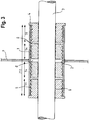
- Fig. 2 shows an embodiment in which two third sealing devices are positioned between the first and the second sealing device I, II.
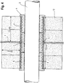
- Fig. 3 shows that the air gaps G between the respective sealing devices I, II, II can be smaller, all depending on the length of the conduit and the length of the respective sealing devices.
- Fig. 4 shows a further reduction of the length of the air gaps G between the respective sealing devices I, II, III.
- the sealed-part has an axial length which corresponds to the length of the conduit 1.
- the air gaps G are minimal in terms of their width in axial direction.
- the sum of the axial lengths of the first, the second and the third sealing devices I, II, III corresponds to the axial length of the conduit 1.
- the axial width of the air gaps G is minimal.
- the mechanical stability is further improved when the air gaps G are smaller.
- the air gaps G remain a good insulation, also when the width (in axial direction) is small.
- conduit 1 is at each end thereof provided with a retainer 7 for retaining at that end one of the first and the second sealing devices I, II in the conduit 1.
- conduit 1 can be provided with a flange 8 to which the retainer 7 can be attached, for instance, by means of bolts and nuts.
- the retainer can only be applied after insertion of the first or the second sealing devices I, II.
- each of the sealing devices I, II, III is flangeless and preferably identical to any of the respective other sealing devices.
- the flangeless plugs are referred to as so-called "DYNATITE" plugs, also commercially available.
- these plugs are designed such that a sealing elastically expands in a transverse direction upon axially applied pressure. This results in annular contact surfaces which expand over a larger width, that is in axial direction, as compared with the situation without an axially applied pressure.
- the annular contact surfaces are present on the inside and the outside of the sealing device.
- the pipe transit system as proposed in this application is extremely suitable for a situation in which metal pipes extend through a conduit and "watertightness after fire" is required.
- Fig. 6 shows an embodiment of a pipe transit system provided by a method according to the invention in which the system comprises four sealing devices, namely the first and the second sealing device I, II and two third sealing devices III.
- Conduit 1 is provided with the retainer 7. Between retainer 7 and the second sealing device II a thermally expandable device 9 is positioned.
- conduit 1 is a so-called multi-part conduit having a main part 10 for holding each of the first, the second, and the third sealing devices I, II, III; and a sleeve-part 11 that is mountable to the main part 10 for holding the thermally expandable device 9.
- the sleeve-part 11 may comprise two shells which along an axial direction are mountable to each other. A transition from the sleeve-part 11 to the main part 10 is preferably free from diameter reducing structures.
- the thermally expandable device 9 may be a multi-part device 9.
- the device may also comprise layers which are concentrically oriented. It is also possible the device comprises a wrappable device, for instance a length of sheet which can be wrapped around pipe 3.
- the device may comprise ethylphenolacetate (EVA). Examples of a thermally expandable device that can be used in such an embodiment can be found in WO 2009/090247 A1 .
- the thermally expandable device 9 will expand, which it can only do in an axial direction A, in the direction of the sealing device I, II, III.
- These sealing devices will then experience an axially applied pressure, and tend to expand in a transverse direction. As explained above, this will result in annular contact surfaces which extend over a larger width, that is in axial direction, as compared with the situation without axially applied pressure. It follows that upon exposure to a nearby fire, the sealing device II and possible more will obtain a firmer grip on pipe 3 and the inner wall 2 of conduit 1. Subsequently, the watertightness after fire is very good.
- the embodiment shown in Fig. 6 is equally very suitable for a situation in which a weakenable pipe, for instance a plastic pipe, extends axially through the conduit 1.
- a weakenable pipe for instance a plastic pipe
- the other embodiments shown may be suitable for plastic pipes if, at least one of the first, the second, and the third sealing devices I, II, III comprises a rubberlike thermally expandable material having a component which causes the material upon exposure to heat to expand to an extent which is much more than the extent to which the material not having these components would expand.
- This component could be expandable graphite and/or intercalated graphite.
- the component causes expansion of the material at the softening temperature of LDPE and/or HDPE, then it is almost certain that the embodiment is suitable for each and every plastic pipe as softening temperatures of LDPE and/or HDPE are amongst the lowest for engineering plastic.
- each embodiment of a transit system according to the invention is preferably symmetrical, having an imaginary transverse cross-sectional plane of the conduit as the (mathematical) mirror plane. This plane may coincide with partition P.
- Conduit 1 is preferably made of metal or hard engineering plastic which is not thermally softenable.
- Fig. 7 shows an embodiment which is very similar to the embodiment shown in Fig. 6 .
- the conduit 1 is internally provided with blocking elements 13 for preventing further displacement of at least one entire first, second or third sealing device I, II, III in the conduit.
- the sealing devices II and III in the form of plugs as shown and between the blocking elements 13 and the thermally expandable device 9 will be axially compressed even further, as pressure is applied from one side by the expansion of the thermally expandable device and the plugs are kept at their position at the other side.
- the annular contact surfaces will enlarge in the axial direction, improving the sealing even further.
- Fig. 8 shows a test tube for testing the watertightness of embodiments of a pipe transit system provided by a method according to the invention, both before and after exposure to a fire.
- Water can enter the vessel V via tube T.
- the water pressure can be measured by a pressure gauge PG.
- Pipe-part PP is sealed off by a blind plug (not shown).
- the embodiment shown in Fig. 4 shows insulation material 12 applied against the outer wall of the conduit and extending by about 200 mm in radial direction. Insulation should ideally be applied to both sides as one never knows on which side a fire will take place. With the insulation it is possible to control to an extent the transport of heat into the conduit 1.
- a person skilled in the art will by routine experiments be able to work out the optimal dimensions for the conduit, the sealing device, the length of the thermally expandable device 9 (if applicable) and the amount and dimensions of the insulation, which will often be a form of mineral wool.
- embodiments of the present invention remained watertight also when no insulation 12 was applied. This applies particularly for the embodiments shown in Figs. 6 and 7 which need heat input for improving the stability and integrity of the sealing.
- the length of the conduit is a parameter which can be explored and optimized for certain situations. Although the drawings often show a certain length, also shorter conduits can be used in embodiments of a system according to the present invention.
- the sealing devices I, II, III can be such that multiple pipes 3 can extend through the conduit 1. Plugs which can be used in such embodiments are shown in WO 2004/111513 A1 , Figs. 4(a) - 4(e) .
- the inner wall 2 of conduit 1 is also in other embodiments provided with a threshold or blocking element 13 to ensure that the third sealing devices III are not inserted too deeply and to ensure that the sealing improves when an axially applied pressure is present.
- a threshold or blocking element 13 coincides with the imaginary plane in which the partition P is positioned.
- Such a blocking element is thus particularly suitable for embodiments shown in Fig. 2 , 3 , 4 and 6 .
Description
- The invention is related to a method for providing a pipe transit system.
- In most man-made constructions having more than one compartment a pipe may be used for transport of flowable media from one compartment to another compartment or for transport of these flowable media from one side of the construction to another side of the construction. Such pipes may also be used for transport of flowable media into a construction.
- Normally compartments are separated by partitions, such as floors, decks, walls, ceilings, etc. For ensuring that a pipe can extend through the partition, an opening is provided in the partition, usually in a shape of a tubular passage, also referred to as a conduit. The diameter of the pipe extending through the opening, such as a conduit, is smaller than the diameter of the opening. The annular space surrounding the pipe in the conduit needs to be sealed off. The quality of that sealing is usually the subject of regulations which take into account the conditions to which the sealing may be exposed under normal circumstances and in the exceptional and unfortunate circumstances such as the occurrence of a nearby fire.
- Such a pipe transit system may also be used, for instance, for two pipes having mutually different diameters connected with each other so that the fluid can flow through both pipes. One of the pipes may, for instance, form a house service connection and have a smaller diameter than a pipe which forms the main line. Such pipes may be used, for instance, for transporting water, gas, oils, liquids, chemicals, etc. The space between the two pipes may also be sealed by a system to which the invention relates.
- Even though a pipe is more often used for transport of flowable media, it is for the pipes used in relation with the presently proposed invention, not at all excluded that the pipe also contains cables, for instance, for telephone, electricity, optical signals, etc. The system provided by the method to which the invention relates may be used for walls of buildings, particularly foundation walls and floors but also ceilings or roofs where, by whatever method, the conduit is positioned in the wall, floor, ceiling or roof.
- Particularly, the system provided by the method to which the invention relates can be used in the construction and/or maintenance of ships and offshore installations. Sections in such constructions are usually formed by placing prefabricated partitions according to a predetermined plan, in the case of a vessel, in a dock of a shipyard. Even before the partitions are placed, feed-through conduits can be provided in the partitions, for instance with the aid of a welding method. After feeding through a pipe through the conduit, a sealing needs to be put in a space between the inner wall of the conduit and the outer wall of the pipe, to complete the pipe transit system.
- Systems provided by the method to which the invention relates, particularly in ships and in offshore installations, are meant to be watertight as well as fire-resistant.
-
GB 2186442 - Apart from the fact that this prior art system is difficult to install, is time-consuming, costly and requires a large inventory control, the system further works unsatisfactorily in the long-run. Rubber, even well vulcanized rubber, has natural relaxation occurring over time. When the rubber has not been properly saturated or vulcanized, also chemical relaxation can occur. This enhances the overall relaxation of the rubber. As a consequence of this, compression bolts or nuts of the compression and packer system described in
GB 2186442 - Clearly, it is highly questionable whether the above-described prior art system remains watertight after a relatively long period of use.
- Given a number of accidents, particularly on cruise ships, there is now a drive for demanding improved pipe transit systems. A new interpretation of SOLAS (Safety Of Life At Sea) II-1, Part B-2, Regulation 13, para. 2.3, is currently applied. Regulation para. 2.3 states: "Lead or heat-sensitive materials shall not be used in systems which penetrate watertight bulkheads, where deterioration of such systems in the event of fire would impair the watertight integrity of the bulkheads". This interpretation is generally referred to as the requirement for "watertightness after fire". Such watertightness after fire has to be tested, during experiments which last up to several days. The pipe transit system, as exposed to fire, will then subsequently be exposed to a water pressure which is raised up to several bars, and at least three bars (corresponding with the pressure of 30 meters below the waterline).
- In relation to this new interpretation, reference is now made to
WO 2007/107342 andWO 2008/023058 , and particularly Fig. 10 thereof. Disclosed is a system comprising a conduit having an inner wall and a pipe extending through the conduit in an axial direction thereof, so that the conduit has a part that is occupied by the pipe. The system further comprises two sealing devices, one inserted in each end of the conduit. These prior art documents explain that it is preferred that the volume of the air entrapped in the conduit between the ends of the sealing devices is as short as possible. This may be achieved by providing a conduit having a length that is just a little bit more than the total length of the two sealing devices, or by insertion of a rubber sleeve (shown in Fig. 10 of these prior art documents by dashed lines) in the conduit sleeve so that the sleeve is positioned between the two sealing devices. It is explained that the air gap between the sealing devices works as thermal insulation. If, as a result of thermal expansion of the air trapped, the pressure of the air gap is built up, the air gap itself may work as a blocking element (against further insertion of a sealing device), facilitating compression of the sealing device that also experiences high pressure from the end of the conduit into which it had been inserted. - This system, designed to provide for a dynamic response to a sudden pressure shock occurring at one end of the conduit, for instance a high pressure wave as the result of a sudden entering of water in a compartment, a tsunami, etc., functions well under the circumstances for which it had been designed. However, a further improvement making this system also easily meeting the "watertight after fire" requirement, is still desirable.
- The invention is defined in the appended claim 1. It provides a pipe transit system comprising a conduit having an inner wall and at least one pipe extending through the conduit in an axial direction thereof so that a conduit has a pipe-part that is occupied by the at least one pipe. The system further comprises a first and a second sealing device inserted in the conduit each for sealing between the inner wall of the conduit and the at least one pipe, so that the conduit also has a sealed part. In the sealed-part between the first and second sealing device at least one third sealing device for sealing between the inner wall of the conduit and the at least one pipe is positioned. Each of the sealing devices is a separate entity and is unconnected to any of the other respective sealing devices.
- An advantage of this pipe transit system provided by the method of the invention is that the third sealing device which is positioned between the first and second sealing device necessarily had to be put in the conduit before both of the first and second sealing device were positioned. This means that the part of the conduit which is occupied by this third sealing device, that ends up between the first and second sealing device, cannot be occupied by air. As a consequence thereof, the length of the conduit that contains air when one of the first and/or second sealing device is inserted is shorter as compared to a situation in which no third sealing device is present. Thus, the air that needs to be compressed when one of the first and/or second sealing devices is inserted, will be compressed into a much smaller volume as compared to a situation in which no "in-between" sealing device had been inserted previously into the conduit. The resistance felt by the second and a first sealing device will, due to the smaller volume available for compression of the air, be relatively high, given that the pressure will rapidly reach a relatively high level. This will have triggered a workman inserting one of the other two sealing devices to release the pressurized air from the gap, for instance by wedging in a small screwdriver between the outside of the sealing device and the inner wall of the conduit or the inside of the sealing device and the outside of the pipe, for release of the pressurized air, to then withdraw the screwdriver completely.
- The end result is that a pipe transit system having more but smaller air gaps is provided and that thus also a much better thermal insulation is provided (each air gap is a good thermal insulator). There is also much less chance that the pressure in an air gap is already at a relatively high point before being heated by a fire that takes place in a nearby environment (given that during installation most likely air has been released from the air gap). Thus, a pipe transit system having more stability upon exposure to heat is provided. Further, the "extra" sealing device in-between the first and the second sealing device also provides mechanical stability in the transit and resistance against deformation. Notably, particularly when the partition is of metal, bulging may occur, sometimes leading to loosening of the sealing devices and even propelling the devices out of the conduit. However, the third plug stabilizes the entire transit and as such enhances safety.
- Thus, when a fire takes place nearby, it will take longer before the sealing device at the unexposed side loses its sealing integrity, if at all. This is because it takes a long time before the temperature increase becomes significant at a side of the conduit that is unexposed to the fire. Each air gap provides thermal insulation. The temperature increase will particularly be suppressed if also insulation material is applied against the partition and the outer side of the conduit. Further, it takes a long time before the air in the gap reaches a high pressure, and it will take longer before the pressure has reached a level up to a point that it might contribute to pushing a sealing device out of the conduit. Also the mechanical stability of the entire transit system is improved.
- This all greatly contributes to the integrity of the overall sealing, first of all by keeping the temperature at the side that is unexposed to the fire relatively low so that also after fire the sealing device at the end of the conduit which is not directly exposed to the fire, continues to provide a watertight sealing. Secondly, the stability of the sealing upon exposure to heat is improved in that it is less likely that a sealing device is already pushed out of the conduit at an early stage of heating the conduit.
- In an embodiment of a pipe transit system provided by the method according to the invention, the sealed-part has an axial length which corresponds to the length of the conduit. In such an embodiment, the widths of the air gaps are minimal, so that the advantages described above are optimal. Each air gap provides thermal insulation which is important. However, these gaps will not be at the expense of mechanical stability.
- In an embodiment of a pipe transit system provided by the method according to the invention, the sum of the axial lengths of the first, the second and the third sealing device corresponds to the axial length of the conduit. Also here, the air gaps are minimal, so that the advantages as described above are optimal.
- In an embodiment of a pipe transit system provided by the method according to the invention, at least one of the first and the second sealing device has a flange for hindering a full insertion of that sealing device into the conduit. Accordingly, that sealing device cannot be inserted any further when the end of the conduit abuts the flange. Thus, the length of the sealed-part as provided by that sealing device is well defined, allowing for selecting the appropriate length for the third sealing device that is positioned in-between the first and the second sealing device of which one is normally at each end of the sealed-part of the conduit.
- In an embodiment of a pipe transit system provided by the method according to the invention, at least one of the sealing devices is free from metal parts for tightening and sealing. Thus, the sealing device provides sealing immediately after insertion into the conduit.
- In an embodiment of a pipe transit system provided by the method according to the invention, at least one of the sealing devices comprises a vulcanized fire-resistant rubber plug. Preferably, each of the sealing devices comprises a vulcanized fire-resistant rubber plug. Advantageously, these are already commercially available in many different dimensions. Further, the material is endothermic in nature, so that it takes a long time before an increase in temperature becomes significant and changes properties of the material.
- The invention as defined in appended claim 1 provides for a method for providing a pipe transit system comprising:
- providing a conduit having an inner wall and at least one pipe extending through the conduit in an axial direction thereof so that the conduit has a pipe-part that is occupied by the at least one pipe,
- inserting and a first and a second sealing device in the conduit, each for sealing between an inner wall of the conduit and the at least one pipe so that the conduit has a sealed-part.
- The method further comprises:
- ensuring that in the sealed-part between the first and the second sealing device at least one third sealing device is positioned for sealing between the inner wall of the conduit and the at least one pipe.
- Each of the first, the second and the third sealing device is a separate entity and is unconnected to any of the other respective sealing devices. By using the method according to the invention it will be possible to insert the first and the second sealing device when the third sealing device has already been positioned in the conduit. Consequently, less volume is available into which the air can be compressed when the first and/or the second sealing device is/are inserted. As a consequence of that, the worker inserting the first and/or the second sealing device will experience a resistance against further insertion due to the pressurized air. That will remind the worker to wedge in a screwdriver or similar device between the inner wall of the conduit and the sealing device or the outer surface of the pipe and the sealing device. This allows for a drop of the air pressure in the gap between the third sealing device and the first or the second sealing device, down to atmospheric levels. Thus, on heating the conduit, for instance due to exposure to a nearby fire, the air pressure in the air gap will only increase from atmospheric level instead of from a level that was higher due to compression of air into the small air gap. Furthermore, the presence of the small air gaps will provide good thermal insulation.
- In the method according to the invention, the method comprises inserting in the conduit the third sealing device before insertion both of the first and the second sealing device, ensuring that the above-described possibility is turned into reality.
- In an embodiment of a method not falling within the scope of the invention, the method comprises inserting in the conduit one of the first or the second sealing device before inserting the third sealing device. In some circumstances all the sealing devices are inserted from one end of the conduit. For this embodiment, it preferably applies that after inserting the third sealing device, the air pressure in the air gap between the third sealing device and the first or the second sealing device is allowed to drop down to atmospheric levels, for instance by wedging in a screwdriver between one of the inserted sealing devices and the inner wall of the conduit or the outer wall of the pipe.
- In general, it applies that for each of the method embodiments described above, an increased air pressure in an air gap between inserted sealing devices is allowed to drop down to atmospheric levels, for instance by wedging in a screwdriver or a similar type of device, between the respective sealing device and the inner wall of the conduit and/or the outside of the pipe. After establishing an atmospheric pressure in the air gap, that screwdriver or similar device can be removed so that the complete sealing can be (re-)established.
- The invention will now further be explained with the aid of a drawing, in which:
-
Fig 1 shows schematically in cross-section a first embodiment of a pipe transit system provided by a method according to the invention; -
Fig. 2 shows schematically in cross-section a second embodiment of a pipe transit system provided by a method according to the invention; -
Fig. 3 shows schematically in cross-section a third embodiment of a pipe transit system provided by a method according to the invention; -
Fig. 4 shows schematically in cross-section a fourth embodiment of a pipe transit system provided by a method according to the invention; -
Fig. 5 shows schematically in cross-section a fifth embodiment of a pipe transit system provided by a method according to the invention; -
Fig. 6 shows schematically in cross-section a sixth embodiment of a pipe transit system provided by a method according to the invention; -
Fig. 7 shows schematically in cross-section a seventh embodiment of a pipe transit system provided by a method according to the invention; and -
Fig. 8 shows schematically in cross-section a set-up for testing before and after exposure to fire the watertightness of embodiments of a pipe transit system provided by a method according to the invention. - In the drawing, like parts have like references.
-
Fig 1 shows schematically in cross-section a first embodiment of a pipe transit system provided by a method according to the invention. The system comprises a conduit 1 which has aninner wall 2. In this example, the conduit is an integral part of a partition P. However, it will be understood that in general the conduit 1 can also be bolted or welded into an opening provided in partition P. Thepipe 3 extends through the conduit 1 in an axial direction A. Accordingly, the conduit 1 has a pipe-part that is occupied bypipe 3. The system further comprises a first and a second sealing device I, II, inserted in the conduit 1. Each of these sealing devices I, II is for sealing between aninner wall 2 of the conduit 1 and thepipe 3, so that the conduit 1 also has a sealed-part. In this sealed-part, between the first and the second device I, II a third sealing device III is positioned also for sealing between theinner wall 2 of the conduit 1 and thepipe 3. Each of the first, the second and the third sealing device I, II, III is a separate entity. Each of the first, the second and the third sealing device, I, II, III is unconnected to any of the other respective sealing devices I, II, III. Small air gaps G are present between the sealing devices I, II, III. - In this example, the first and the second sealing device I, II each have a
flange 4 for hindering a full insertion of that sealing device into the conduit 1. - The third sealing device III is flangeless. Preferably, at least one of the first, the second, and the third sealing device I, II, III is free from metal parts for tightening the sealing. Ideally, this applies to each of the first, the second, and the third sealing device I, II, III. Preferably, at least one of the first, the second and the third sealing device I, II, III comprises a vulcanized fire-resistant rubber plug. More preferably, this applies to each of the first, the second, and the third sealing device I, II, III.
- Further, it is preferable that the first, the second, and the third sealing device I, II, III is provided with
outer ribs 5 having tops spaced apart in longitudinal direction A for realizing, in use, annular contact surfaces which are each closed in itself in a circumferential direction between the sealing device I, II, III and theinner wall 2 of the conduit 1. Further, equally preferable, it applies that at least one of the first, the second, and the third sealing device I, II, III is provided with inner ribs having tops spaced apart in a longitudinal direction for realizing, in use, annular contact surfaces which are closed in itself in a circumferential direction between the respective sealing device and thepipe 3. - The vulcanized fire-resistant rubber is preferably of a silicon based rubber. It is possible that at least one of the first, the second, and the third sealing device I, II, III comprises at least two segmental parts.
- The sealing device I, II are preferably as described in
WO 2004/111513 A1 . In that reference, also the outer ribs are more clearly shown. Plugs which are very useful as sealings in embodiments of the present invention, are commercially available from the Applicant, as promoted under the trademark name "SLIPSIL" plugs. Notably, because of the larger number of ribs, the mechanical stability is very good, providing good resistance to deformation. The air gaps G remain air gaps G. This also ensures that the thermal insulation provided by the air gaps remains intact. - The third sealing device III is preferably also in the shape of a plug, for instance, as shown in
WO 2008/023058 , particularlyFigs. 2-10 . Such plugs elastically expand somewhat in transverse direction upon an axially applied pressure. Of course, this elastic expansion is only possible if the plug is not inserted in a conduit. When such a sealing device sealing against the inner wall of that conduit and is then subjected to an axially applied pressure, the annular contact surfaces which extend in circumferential direction extend in axial direction. That is, the width of these annular contact surfaces will be enhanced, improving the sealing integrity. This will also further improve the mechanical stability without loss of the air gaps as the air cannot escape. This leads to an improved sealing. - It is to be noted that the invention can also be applied in a situation in which more than one pipe extends through the conduit 1. Cross-sections of suitable sealing devices are shown in
WO 2004/111513 A1 , particularlyFig. 4(a) - 4(e) . - Although in a case in which the first and second sealing device I, II each have a flange, the number of these first and second sealing devices is limited, the number of third sealing devices III can be higher than one. The number of third sealing devices III depends on the length of the conduit 1, the length of the first and the second sealing device I, II and the length of the third sealing device III.
Fig. 2 shows an embodiment in which two third sealing devices are positioned between the first and the second sealing device I, II. -
Fig. 3 shows that the air gaps G between the respective sealing devices I, II, II can be smaller, all depending on the length of the conduit and the length of the respective sealing devices.Fig. 4 shows a further reduction of the length of the air gaps G between the respective sealing devices I, II, III. Preferably, the sealed-part has an axial length which corresponds to the length of the conduit 1. In such a situation, the air gaps G are minimal in terms of their width in axial direction. The sum of the axial lengths of the first, the second and the third sealing devices I, II, III corresponds to the axial length of the conduit 1. Also for this situation, the axial width of the air gaps G is minimal. As explained above, the mechanical stability is further improved when the air gaps G are smaller. The air gaps G remain a good insulation, also when the width (in axial direction) is small. - In the embodiment shown in
Fig. 4 , the conduit is at each end thereof provided with aretainer 7 for retaining at that end one of the first and the second sealing devices I, II in the conduit 1. As shown, conduit 1 can be provided with a flange 8 to which theretainer 7 can be attached, for instance, by means of bolts and nuts. Clearly, the retainer can only be applied after insertion of the first or the second sealing devices I, II. - As seen in
Fig. 5 , in an embodiment, each of the sealing devices I, II, III is flangeless and preferably identical to any of the respective other sealing devices. - For a more detailed description of the sealing devices I, II, III as shown inn
Fig. 5 , reference is made toWO 2008/023058 of the present Applicant, particularlyFigs. 2-10 of that document. The flangeless plugs are referred to as so-called "DYNATITE" plugs, also commercially available. As explained above, these plugs are designed such that a sealing elastically expands in a transverse direction upon axially applied pressure. This results in annular contact surfaces which expand over a larger width, that is in axial direction, as compared with the situation without an axially applied pressure. The annular contact surfaces are present on the inside and the outside of the sealing device. An advantage of using these plugs as sealing devices in embodiments of the present invention is that upon axially applied pressure, the plugs will obtain a firmer grip on thepipe 3. - The pipe transit system as proposed in this application is extremely suitable for a situation in which metal pipes extend through a conduit and "watertightness after fire" is required.
-
Fig. 6 shows an embodiment of a pipe transit system provided by a method according to the invention in which the system comprises four sealing devices, namely the first and the second sealing device I, II and two third sealing devices III. Conduit 1 is provided with theretainer 7. Betweenretainer 7 and the second sealing device II a thermallyexpandable device 9 is positioned. For this embodiment, conduit 1 is a so-called multi-part conduit having amain part 10 for holding each of the first, the second, and the third sealing devices I, II, III; and a sleeve-part 11 that is mountable to themain part 10 for holding the thermallyexpandable device 9. The sleeve-part 11 may comprise two shells which along an axial direction are mountable to each other. A transition from the sleeve-part 11 to themain part 10 is preferably free from diameter reducing structures. - The thermally
expandable device 9 may be amulti-part device 9. The device may also comprise layers which are concentrically oriented. It is also possible the device comprises a wrappable device, for instance a length of sheet which can be wrapped aroundpipe 3. The device may comprise ethylphenolacetate (EVA). Examples of a thermally expandable device that can be used in such an embodiment can be found inWO 2009/090247 A1 . - If
pipe 3 is of metal, then the thermallyexpandable device 9 will expand, which it can only do in an axial direction A, in the direction of the sealing device I, II, III. These sealing devices will then experience an axially applied pressure, and tend to expand in a transverse direction. As explained above, this will result in annular contact surfaces which extend over a larger width, that is in axial direction, as compared with the situation without axially applied pressure. It follows that upon exposure to a nearby fire, the sealing device II and possible more will obtain a firmer grip onpipe 3 and theinner wall 2 of conduit 1. Subsequently, the watertightness after fire is very good. - The embodiment shown in
Fig. 6 is equally very suitable for a situation in which a weakenable pipe, for instance a plastic pipe, extends axially through the conduit 1. Also the other embodiments shown may be suitable for plastic pipes if, at least one of the first, the second, and the third sealing devices I, II, III comprises a rubberlike thermally expandable material having a component which causes the material upon exposure to heat to expand to an extent which is much more than the extent to which the material not having these components would expand. This component could be expandable graphite and/or intercalated graphite. If the component causes expansion of the material at the softening temperature of LDPE and/or HDPE, then it is almost certain that the embodiment is suitable for each and every plastic pipe as softening temperatures of LDPE and/or HDPE are amongst the lowest for engineering plastic. - As it is often not known on which side of a partition P a fire will break out, each embodiment of a transit system according to the invention is preferably symmetrical, having an imaginary transverse cross-sectional plane of the conduit as the (mathematical) mirror plane. This plane may coincide with partition P.
- Conduit 1 is preferably made of metal or hard engineering plastic which is not thermally softenable.
-
Fig. 7 shows an embodiment which is very similar to the embodiment shown inFig. 6 . However, inFig. 7 the conduit 1 is internally provided with blocking elements 13 for preventing further displacement of at least one entire first, second or third sealing device I, II, III in the conduit. Thus, the sealing devices II and III in the form of plugs as shown and between the blocking elements 13 and the thermallyexpandable device 9 will be axially compressed even further, as pressure is applied from one side by the expansion of the thermally expandable device and the plugs are kept at their position at the other side. The annular contact surfaces will enlarge in the axial direction, improving the sealing even further. -
Fig. 8 shows a test tube for testing the watertightness of embodiments of a pipe transit system provided by a method according to the invention, both before and after exposure to a fire. As shown, a part of the partition P in which the conduit 1 is mounted tightly and sealingly fixed against an upper outerward flange F of a vessel V. Water can enter the vessel V via tube T. The water pressure can be measured by a pressure gauge PG. Pipe-part PP is sealed off by a blind plug (not shown). With this test set-up, it has been shown that the watertightness is maintained for each and every embodiment shown above. When the watertightness measured before exposure to a fire as compared to the watertightness as measured after exposure to a fire, it turned out that the watertightness was still maintained, at least for 30 minutes up to 1 bar, and for a number of embodiments even up to weeks at a water pressure of 4 bar. For embodiments as shown inFigs. 6 and7 it applies that the watertightness is after exposure to a fire even better than before exposure to a fire, in that it can sustain after exposure to a fire an even higher water pressure. - For each embodiment clearly the sealing at the unexposed side of the conduit remained fully intact or had even been improved. "Watertightness after fire" has been achieved.
- The embodiment shown in
Fig. 4 showsinsulation material 12 applied against the outer wall of the conduit and extending by about 200 mm in radial direction. Insulation should ideally be applied to both sides as one never knows on which side a fire will take place. With the insulation it is possible to control to an extent the transport of heat into the conduit 1. A person skilled in the art will by routine experiments be able to work out the optimal dimensions for the conduit, the sealing device, the length of the thermally expandable device 9 (if applicable) and the amount and dimensions of the insulation, which will often be a form of mineral wool. However, it has turned out that embodiments of the present invention remained watertight also when noinsulation 12 was applied. This applies particularly for the embodiments shown inFigs. 6 and7 which need heat input for improving the stability and integrity of the sealing. - Also the length of the conduit is a parameter which can be explored and optimized for certain situations. Although the drawings often show a certain length, also shorter conduits can be used in embodiments of a system according to the present invention.
- As indicated earlier above, the invention is not limited to the embodiments shown in the drawing. Many modifications are possible. The sealing devices I, II, III can be such that
multiple pipes 3 can extend through the conduit 1. Plugs which can be used in such embodiments are shown inWO 2004/111513 A1 ,Figs. 4(a) - 4(e) . - Although only shown in
Fig. 7 , it is possible that theinner wall 2 of conduit 1 is also in other embodiments provided with a threshold or blocking element 13 to ensure that the third sealing devices III are not inserted too deeply and to ensure that the sealing improves when an axially applied pressure is present. Often, such a threshold or blocking element 13 coincides with the imaginary plane in which the partition P is positioned. Such a blocking element is thus particularly suitable for embodiments shown inFig. 2 ,3 ,4 and6 . - The invention is not limited to the embodiments shown in the drawing. Many modifications are possible. Each of these modifications are understood as being well within the framework of the invention as long as they fall within the scope of protection defined by the appended claims.
Claims (16)
- Method for providing a pipe transit system comprising:providing a conduit (1) having an inner wall and at least one pipe (3) extending through the conduit in an axial direction thereof so that the conduit has a pipe-part that is occupied by the at least one pipe,inserting a first and a second sealing (I, II) in the conduit, each for sealing between an inner wall of the conduit and the at least one pipe so that the conduit also has a sealed-part,wherein the method is characterised by: ensuring that in the sealed-part between the first and the second sealing device (I, II) at least one third sealing device (III) is positioned for sealing between the inner wall of the conduit and the at least one pipe,wherein each of the first, the second and the third sealing device is a separate entity and is unconnected to any of the other respective sealing devices,wherein the method comprises inserting in the conduit the third sealing device before inserting both of the first and second sealing devices, and wherein the method comprises allowing for a drop of the air pressure in the gap (G) between the third sealing device and the first or the second sealing device, down to atmospheric levels, wherein the sealed-part has an axial length which corresponds to the length of the conduit.
- Method according to claim 1, wherein the sum of the axial lengths of the first, the second and the third sealing device (I, II, III) corresponds to the axial length of the conduit.
- Method according to claim 1 or 2, wherein of the first and the second sealing device at least one has a flange (4) for hindering a full insertion of that sealing device into the conduit.
- Method according to any one of claims 1-3, wherein at least one of the first, second and third sealing devices is free from metal parts for tightening the sealing.
- Method according to any one of claims 1-4, wherein each of the first, the second and the third sealing device is free from metal parts for tightening the sealing.
- A Method according to any one of claims 1-5, wherein at least one of the first, the second and the third sealing device comprises a vulcanized fire-resistant rubber plug.
- A method according to any one of claims 1-6, wherein at least one of the first, the second and the third sealing device is provided with outer ribs (5) having tops spaced apart in longitudinal direction for realizing, in use, annular contact surfaces which are each closed in itself in a circumferential direction between the sealing device and the inner wall of the conduit.
- A method according to any one of the claims 1-7, wherein at least one of the first, the second and the third sealing device is provided with inner ribs (6) having tops spaced apart in longitudinal direction for realizing, in use, annular contact surfaces which are closed in itself in a circumferential direction between the sealing device and the at least one pipe.
- A method according to any one of the claims 1-8, wherein at least one of the first, the second and the third sealing device comprises at least two segmental parts.
- A method according to any one of the claims 1-9, wherein the conduit is of metal or a hard engineering plastic which is not thermally softenable.
- A method according to any one of the claims 1-10, wherein the system is symmetrical, an imaginary transverse cross-sectional plane of the conduit being the mirror plane.
- A method according to any one of the claims 1-11, wherein at least one of the first, the second and the third sealing device comprises a rubberlike thermally expandable material having a component which causes the material on exposure to heat to expand to an extent which is much more than the extent to which that material not having these components would expand.
- A method according to any one of claims 1-12, wherein at least one of the first, the second and the third sealing device elastically expands in transverse direction upon an axially applied pressure.
- A method according to any one of the previous claims comprises: providing at at least one end of the conduit a retainer (7) for retaining at that end each of the first, the second and the third sealing devices in the conduit.
- A method according to any one of claims 1-14, wherein the conduit is internally provided with a blocking element (13) for preventing further displacement of at least one of the first, the second or the third sealing device inwards of the conduit.
- A method according to any one of claims 1-15, wherein air in air gaps formed in the sealed-part between the respective sealing devices is at atmospheric pressure.
Applications Claiming Priority (2)
| Application Number | Priority Date | Filing Date | Title |
|---|---|---|---|
| NL1040476A NL1040476C2 (en) | 2013-10-31 | 2013-10-31 | A pipe transit system. |
| PCT/EP2014/071981 WO2015062856A1 (en) | 2013-10-31 | 2014-10-14 | A pipe transit system |
Publications (2)
| Publication Number | Publication Date |
|---|---|
| EP3063448A1 EP3063448A1 (en) | 2016-09-07 |
| EP3063448B1 true EP3063448B1 (en) | 2018-07-18 |
Family
ID=50156835
Family Applications (1)
| Application Number | Title | Priority Date | Filing Date |
|---|---|---|---|
| EP14786161.1A Active EP3063448B1 (en) | 2013-10-31 | 2014-10-14 | Method for providing a pipe transit system |
Country Status (4)
| Country | Link |
|---|---|
| EP (1) | EP3063448B1 (en) |
| ES (1) | ES2685900T3 (en) |
| NL (1) | NL1040476C2 (en) |
| WO (1) | WO2015062856A1 (en) |
Families Citing this family (1)
| Publication number | Priority date | Publication date | Assignee | Title |
|---|---|---|---|---|
| DE102015112285A1 (en) * | 2015-07-28 | 2017-02-02 | R.Stahl Schaltgeräte GmbH | Explosion-proof arrangement and method for the production thereof |
Family Cites Families (5)
| Publication number | Priority date | Publication date | Assignee | Title |
|---|---|---|---|---|
| FR2179523A2 (en) * | 1972-04-11 | 1973-11-23 | Foa Michel | |
| NL1011718C2 (en) * | 1999-04-01 | 2000-10-03 | Beele Eng Bv | Electrically conductive paste. |
| NL1016749C2 (en) * | 2000-11-30 | 2002-05-31 | Beele Eng Bv | Sealing system. |
| US20040016190A1 (en) * | 2002-07-26 | 2004-01-29 | Radke Duwayne C. | Modular device to create a passage through a partition |
| EP1837573B1 (en) * | 2006-03-20 | 2012-09-12 | Beele Engineering B.V. | System for dynamically sealing a conduit sleeve through which a pipe or cable extends |
-
2013
- 2013-10-31 NL NL1040476A patent/NL1040476C2/en active
-
2014
- 2014-10-14 WO PCT/EP2014/071981 patent/WO2015062856A1/en active Application Filing
- 2014-10-14 EP EP14786161.1A patent/EP3063448B1/en active Active
- 2014-10-14 ES ES14786161.1T patent/ES2685900T3/en active Active
Non-Patent Citations (1)
| Title |
|---|
| None * |
Also Published As
| Publication number | Publication date |
|---|---|
| WO2015062856A1 (en) | 2015-05-07 |
| ES2685900T3 (en) | 2018-10-15 |
| NL1040476C2 (en) | 2015-05-04 |
| EP3063448A1 (en) | 2016-09-07 |
Similar Documents
| Publication | Publication Date | Title |
|---|---|---|
| EP1837573B1 (en) | System for dynamically sealing a conduit sleeve through which a pipe or cable extends | |
| US8490353B2 (en) | System for dynamically sealing at least one conduit through which a pipe or cable extends | |
| EP2126438B1 (en) | System and method for sealing in a conduit a space between an inner wall of the conduit and at least one pipe or cable extending through the conduit | |
| US8783693B2 (en) | Method and sealing system for sealing an annular space between a rigid conduit and a pipe, tube or duct extending through the conduit and made of a thermally weakenable material | |
| JP5312480B2 (en) | A fire prevention system in which a heat degradable tube is disposed in a conduit extending therein, a method of arranging the system, and a conduit including the system | |
| WO2006097290A9 (en) | Fire resisting system and method for providing such system | |
| EP3058261B1 (en) | A pipe transit system | |
| EP3063448B1 (en) | Method for providing a pipe transit system | |
| EP3058260B1 (en) | A pipe transit system for plastic pipes | |
| AU2016328780A1 (en) | A system and method for sealing one end of an existing conduit through which a number of cables extend |
Legal Events
| Date | Code | Title | Description |
|---|---|---|---|
| PUAI | Public reference made under article 153(3) epc to a published international application that has entered the european phase |
Free format text: ORIGINAL CODE: 0009012 |
|
| 17P | Request for examination filed |
Effective date: 20160506 |
|
| AK | Designated contracting states |
Kind code of ref document: A1 Designated state(s): AL AT BE BG CH CY CZ DE DK EE ES FI FR GB GR HR HU IE IS IT LI LT LU LV MC MK MT NL NO PL PT RO RS SE SI SK SM TR |
|
| AX | Request for extension of the european patent |
Extension state: BA ME |
|
| DAX | Request for extension of the european patent (deleted) | ||
| GRAP | Despatch of communication of intention to grant a patent |
Free format text: ORIGINAL CODE: EPIDOSNIGR1 |
|
| INTG | Intention to grant announced |
Effective date: 20180216 |
|
| GRAS | Grant fee paid |
Free format text: ORIGINAL CODE: EPIDOSNIGR3 |
|
| GRAA | (expected) grant |
Free format text: ORIGINAL CODE: 0009210 |
|
| AK | Designated contracting states |
Kind code of ref document: B1 Designated state(s): AL AT BE BG CH CY CZ DE DK EE ES FI FR GB GR HR HU IE IS IT LI LT LU LV MC MK MT NL NO PL PT RO RS SE SI SK SM TR |
|
| REG | Reference to a national code |
Ref country code: GB Ref legal event code: FG4D |
|
| RIN1 | Information on inventor provided before grant (corrected) |
Inventor name: BEELE, JOHANNES ALFRED |
|
| REG | Reference to a national code |
Ref country code: CH Ref legal event code: EP |
|
| REG | Reference to a national code |
Ref country code: IE Ref legal event code: FG4D |
|
| REG | Reference to a national code |
Ref country code: AT Ref legal event code: REF Ref document number: 1019733 Country of ref document: AT Kind code of ref document: T Effective date: 20180815 |
|
| REG | Reference to a national code |
Ref country code: DE Ref legal event code: R096 Ref document number: 602014028785 Country of ref document: DE |
|
| REG | Reference to a national code |
Ref country code: NL Ref legal event code: FP |
|
| REG | Reference to a national code |
Ref country code: SE Ref legal event code: TRGR |
|
| REG | Reference to a national code |
Ref country code: ES Ref legal event code: FG2A Ref document number: 2685900 Country of ref document: ES Kind code of ref document: T3 Effective date: 20181015 |
|
| REG | Reference to a national code |
Ref country code: FR Ref legal event code: PLFP Year of fee payment: 5 |
|
| REG | Reference to a national code |
Ref country code: LT Ref legal event code: MG4D |
|
| PG25 | Lapsed in a contracting state [announced via postgrant information from national office to epo] |
Ref country code: LT Free format text: LAPSE BECAUSE OF FAILURE TO SUBMIT A TRANSLATION OF THE DESCRIPTION OR TO PAY THE FEE WITHIN THE PRESCRIBED TIME-LIMIT Effective date: 20180718 Ref country code: BG Free format text: LAPSE BECAUSE OF FAILURE TO SUBMIT A TRANSLATION OF THE DESCRIPTION OR TO PAY THE FEE WITHIN THE PRESCRIBED TIME-LIMIT Effective date: 20181018 Ref country code: RS Free format text: LAPSE BECAUSE OF FAILURE TO SUBMIT A TRANSLATION OF THE DESCRIPTION OR TO PAY THE FEE WITHIN THE PRESCRIBED TIME-LIMIT Effective date: 20180718 Ref country code: IS Free format text: LAPSE BECAUSE OF FAILURE TO SUBMIT A TRANSLATION OF THE DESCRIPTION OR TO PAY THE FEE WITHIN THE PRESCRIBED TIME-LIMIT Effective date: 20181118 Ref country code: PL Free format text: LAPSE BECAUSE OF FAILURE TO SUBMIT A TRANSLATION OF THE DESCRIPTION OR TO PAY THE FEE WITHIN THE PRESCRIBED TIME-LIMIT Effective date: 20180718 Ref country code: GR Free format text: LAPSE BECAUSE OF FAILURE TO SUBMIT A TRANSLATION OF THE DESCRIPTION OR TO PAY THE FEE WITHIN THE PRESCRIBED TIME-LIMIT Effective date: 20181019 Ref country code: NO Free format text: LAPSE BECAUSE OF FAILURE TO SUBMIT A TRANSLATION OF THE DESCRIPTION OR TO PAY THE FEE WITHIN THE PRESCRIBED TIME-LIMIT Effective date: 20181018 |
|
| PG25 | Lapsed in a contracting state [announced via postgrant information from national office to epo] |
Ref country code: LV Free format text: LAPSE BECAUSE OF FAILURE TO SUBMIT A TRANSLATION OF THE DESCRIPTION OR TO PAY THE FEE WITHIN THE PRESCRIBED TIME-LIMIT Effective date: 20180718 Ref country code: AL Free format text: LAPSE BECAUSE OF FAILURE TO SUBMIT A TRANSLATION OF THE DESCRIPTION OR TO PAY THE FEE WITHIN THE PRESCRIBED TIME-LIMIT Effective date: 20180718 Ref country code: HR Free format text: LAPSE BECAUSE OF FAILURE TO SUBMIT A TRANSLATION OF THE DESCRIPTION OR TO PAY THE FEE WITHIN THE PRESCRIBED TIME-LIMIT Effective date: 20180718 |
|
| REG | Reference to a national code |
Ref country code: DE Ref legal event code: R097 Ref document number: 602014028785 Country of ref document: DE |
|
| PG25 | Lapsed in a contracting state [announced via postgrant information from national office to epo] |
Ref country code: EE Free format text: LAPSE BECAUSE OF FAILURE TO SUBMIT A TRANSLATION OF THE DESCRIPTION OR TO PAY THE FEE WITHIN THE PRESCRIBED TIME-LIMIT Effective date: 20180718 Ref country code: RO Free format text: LAPSE BECAUSE OF FAILURE TO SUBMIT A TRANSLATION OF THE DESCRIPTION OR TO PAY THE FEE WITHIN THE PRESCRIBED TIME-LIMIT Effective date: 20180718 Ref country code: CZ Free format text: LAPSE BECAUSE OF FAILURE TO SUBMIT A TRANSLATION OF THE DESCRIPTION OR TO PAY THE FEE WITHIN THE PRESCRIBED TIME-LIMIT Effective date: 20180718 |
|
| PLBE | No opposition filed within time limit |
Free format text: ORIGINAL CODE: 0009261 |
|
| STAA | Information on the status of an ep patent application or granted ep patent |
Free format text: STATUS: NO OPPOSITION FILED WITHIN TIME LIMIT |
|
| PG25 | Lapsed in a contracting state [announced via postgrant information from national office to epo] |
Ref country code: DK Free format text: LAPSE BECAUSE OF FAILURE TO SUBMIT A TRANSLATION OF THE DESCRIPTION OR TO PAY THE FEE WITHIN THE PRESCRIBED TIME-LIMIT Effective date: 20180718 Ref country code: SM Free format text: LAPSE BECAUSE OF FAILURE TO SUBMIT A TRANSLATION OF THE DESCRIPTION OR TO PAY THE FEE WITHIN THE PRESCRIBED TIME-LIMIT Effective date: 20180718 Ref country code: SK Free format text: LAPSE BECAUSE OF FAILURE TO SUBMIT A TRANSLATION OF THE DESCRIPTION OR TO PAY THE FEE WITHIN THE PRESCRIBED TIME-LIMIT Effective date: 20180718 |
|
| REG | Reference to a national code |
Ref country code: CH Ref legal event code: PL |
|
| 26N | No opposition filed |
Effective date: 20190423 |
|
| REG | Reference to a national code |
Ref country code: BE Ref legal event code: MM Effective date: 20181031 |
|
| PG25 | Lapsed in a contracting state [announced via postgrant information from national office to epo] |
Ref country code: LU Free format text: LAPSE BECAUSE OF NON-PAYMENT OF DUE FEES Effective date: 20181014 Ref country code: MC Free format text: LAPSE BECAUSE OF FAILURE TO SUBMIT A TRANSLATION OF THE DESCRIPTION OR TO PAY THE FEE WITHIN THE PRESCRIBED TIME-LIMIT Effective date: 20180718 |
|
| REG | Reference to a national code |
Ref country code: IE Ref legal event code: MM4A |
|
| PG25 | Lapsed in a contracting state [announced via postgrant information from national office to epo] |
Ref country code: LI Free format text: LAPSE BECAUSE OF NON-PAYMENT OF DUE FEES Effective date: 20181031 Ref country code: CH Free format text: LAPSE BECAUSE OF NON-PAYMENT OF DUE FEES Effective date: 20181031 Ref country code: BE Free format text: LAPSE BECAUSE OF NON-PAYMENT OF DUE FEES Effective date: 20181031 Ref country code: SI Free format text: LAPSE BECAUSE OF FAILURE TO SUBMIT A TRANSLATION OF THE DESCRIPTION OR TO PAY THE FEE WITHIN THE PRESCRIBED TIME-LIMIT Effective date: 20180718 |
|
| PG25 | Lapsed in a contracting state [announced via postgrant information from national office to epo] |
Ref country code: IE Free format text: LAPSE BECAUSE OF NON-PAYMENT OF DUE FEES Effective date: 20181014 |
|
| PG25 | Lapsed in a contracting state [announced via postgrant information from national office to epo] |
Ref country code: MT Free format text: LAPSE BECAUSE OF NON-PAYMENT OF DUE FEES Effective date: 20181014 |
|
| PG25 | Lapsed in a contracting state [announced via postgrant information from national office to epo] |
Ref country code: TR Free format text: LAPSE BECAUSE OF FAILURE TO SUBMIT A TRANSLATION OF THE DESCRIPTION OR TO PAY THE FEE WITHIN THE PRESCRIBED TIME-LIMIT Effective date: 20180718 |
|
| PG25 | Lapsed in a contracting state [announced via postgrant information from national office to epo] |
Ref country code: PT Free format text: LAPSE BECAUSE OF FAILURE TO SUBMIT A TRANSLATION OF THE DESCRIPTION OR TO PAY THE FEE WITHIN THE PRESCRIBED TIME-LIMIT Effective date: 20180718 |
|
| PG25 | Lapsed in a contracting state [announced via postgrant information from national office to epo] |
Ref country code: HU Free format text: LAPSE BECAUSE OF FAILURE TO SUBMIT A TRANSLATION OF THE DESCRIPTION OR TO PAY THE FEE WITHIN THE PRESCRIBED TIME-LIMIT; INVALID AB INITIO Effective date: 20141014 Ref country code: MK Free format text: LAPSE BECAUSE OF NON-PAYMENT OF DUE FEES Effective date: 20180718 Ref country code: CY Free format text: LAPSE BECAUSE OF FAILURE TO SUBMIT A TRANSLATION OF THE DESCRIPTION OR TO PAY THE FEE WITHIN THE PRESCRIBED TIME-LIMIT Effective date: 20180718 |
|
| REG | Reference to a national code |
Ref country code: AT Ref legal event code: UEP Ref document number: 1019733 Country of ref document: AT Kind code of ref document: T Effective date: 20180718 |
|
| P01 | Opt-out of the competence of the unified patent court (upc) registered |
Effective date: 20230518 |
|
| PGFP | Annual fee paid to national office [announced via postgrant information from national office to epo] |
Ref country code: SE Payment date: 20230918 Year of fee payment: 10 Ref country code: NL Payment date: 20231018 Year of fee payment: 10 |
|
| PGFP | Annual fee paid to national office [announced via postgrant information from national office to epo] |
Ref country code: GB Payment date: 20231026 Year of fee payment: 10 |
|
| PGFP | Annual fee paid to national office [announced via postgrant information from national office to epo] |
Ref country code: ES Payment date: 20231102 Year of fee payment: 10 |
|
| PGFP | Annual fee paid to national office [announced via postgrant information from national office to epo] |
Ref country code: IT Payment date: 20231023 Year of fee payment: 10 Ref country code: FR Payment date: 20231018 Year of fee payment: 10 Ref country code: FI Payment date: 20231004 Year of fee payment: 10 Ref country code: DE Payment date: 20231018 Year of fee payment: 10 Ref country code: AT Payment date: 20231030 Year of fee payment: 10 |