EP1837566B1 - Vorrichtung und Ventilkombination zur Fliessumkehr von strömenden Medien - Google Patents
Vorrichtung und Ventilkombination zur Fliessumkehr von strömenden Medien Download PDFInfo
- Publication number
- EP1837566B1 EP1837566B1 EP20070005565 EP07005565A EP1837566B1 EP 1837566 B1 EP1837566 B1 EP 1837566B1 EP 20070005565 EP20070005565 EP 20070005565 EP 07005565 A EP07005565 A EP 07005565A EP 1837566 B1 EP1837566 B1 EP 1837566B1
- Authority
- EP
- European Patent Office
- Prior art keywords
- valve
- combination
- block
- valve combination
- modules
- Prior art date
- Legal status (The legal status is an assumption and is not a legal conclusion. Google has not performed a legal analysis and makes no representation as to the accuracy of the status listed.)
- Ceased
Links
Images




Classifications
-
- F—MECHANICAL ENGINEERING; LIGHTING; HEATING; WEAPONS; BLASTING
- F16—ENGINEERING ELEMENTS AND UNITS; GENERAL MEASURES FOR PRODUCING AND MAINTAINING EFFECTIVE FUNCTIONING OF MACHINES OR INSTALLATIONS; THERMAL INSULATION IN GENERAL
- F16K—VALVES; TAPS; COCKS; ACTUATING-FLOATS; DEVICES FOR VENTING OR AERATING
- F16K11/00—Multiple-way valves, e.g. mixing valves; Pipe fittings incorporating such valves
- F16K11/10—Multiple-way valves, e.g. mixing valves; Pipe fittings incorporating such valves with two or more closure members not moving as a unit
- F16K11/20—Multiple-way valves, e.g. mixing valves; Pipe fittings incorporating such valves with two or more closure members not moving as a unit operated by separate actuating members
- F16K11/22—Multiple-way valves, e.g. mixing valves; Pipe fittings incorporating such valves with two or more closure members not moving as a unit operated by separate actuating members with an actuating member for each valve, e.g. interconnected to form multiple-way valves
-
- F—MECHANICAL ENGINEERING; LIGHTING; HEATING; WEAPONS; BLASTING
- F16—ENGINEERING ELEMENTS AND UNITS; GENERAL MEASURES FOR PRODUCING AND MAINTAINING EFFECTIVE FUNCTIONING OF MACHINES OR INSTALLATIONS; THERMAL INSULATION IN GENERAL
- F16K—VALVES; TAPS; COCKS; ACTUATING-FLOATS; DEVICES FOR VENTING OR AERATING
- F16K27/00—Construction of housing; Use of materials therefor
- F16K27/02—Construction of housing; Use of materials therefor of lift valves
- F16K27/0263—Construction of housing; Use of materials therefor of lift valves multiple way valves
-
- F—MECHANICAL ENGINEERING; LIGHTING; HEATING; WEAPONS; BLASTING
- F16—ENGINEERING ELEMENTS AND UNITS; GENERAL MEASURES FOR PRODUCING AND MAINTAINING EFFECTIVE FUNCTIONING OF MACHINES OR INSTALLATIONS; THERMAL INSULATION IN GENERAL
- F16K—VALVES; TAPS; COCKS; ACTUATING-FLOATS; DEVICES FOR VENTING OR AERATING
- F16K27/00—Construction of housing; Use of materials therefor
- F16K27/02—Construction of housing; Use of materials therefor of lift valves
- F16K27/029—Electromagnetically actuated valves
-
- F—MECHANICAL ENGINEERING; LIGHTING; HEATING; WEAPONS; BLASTING
- F16—ENGINEERING ELEMENTS AND UNITS; GENERAL MEASURES FOR PRODUCING AND MAINTAINING EFFECTIVE FUNCTIONING OF MACHINES OR INSTALLATIONS; THERMAL INSULATION IN GENERAL
- F16K—VALVES; TAPS; COCKS; ACTUATING-FLOATS; DEVICES FOR VENTING OR AERATING
- F16K31/00—Actuating devices; Operating means; Releasing devices
- F16K31/02—Actuating devices; Operating means; Releasing devices electric; magnetic
- F16K31/06—Actuating devices; Operating means; Releasing devices electric; magnetic using a magnet, e.g. diaphragm valves, cutting off by means of a liquid
- F16K31/0603—Multiple-way valves
- F16K31/0606—Multiple-way valves fluid passing through the solenoid coil
-
- F—MECHANICAL ENGINEERING; LIGHTING; HEATING; WEAPONS; BLASTING
- F16—ENGINEERING ELEMENTS AND UNITS; GENERAL MEASURES FOR PRODUCING AND MAINTAINING EFFECTIVE FUNCTIONING OF MACHINES OR INSTALLATIONS; THERMAL INSULATION IN GENERAL
- F16K—VALVES; TAPS; COCKS; ACTUATING-FLOATS; DEVICES FOR VENTING OR AERATING
- F16K31/00—Actuating devices; Operating means; Releasing devices
- F16K31/02—Actuating devices; Operating means; Releasing devices electric; magnetic
- F16K31/06—Actuating devices; Operating means; Releasing devices electric; magnetic using a magnet, e.g. diaphragm valves, cutting off by means of a liquid
- F16K31/0603—Multiple-way valves
- F16K31/0624—Lift valves
- F16K31/0627—Lift valves with movable valve member positioned between seats
-
- F—MECHANICAL ENGINEERING; LIGHTING; HEATING; WEAPONS; BLASTING
- F16—ENGINEERING ELEMENTS AND UNITS; GENERAL MEASURES FOR PRODUCING AND MAINTAINING EFFECTIVE FUNCTIONING OF MACHINES OR INSTALLATIONS; THERMAL INSULATION IN GENERAL
- F16K—VALVES; TAPS; COCKS; ACTUATING-FLOATS; DEVICES FOR VENTING OR AERATING
- F16K31/00—Actuating devices; Operating means; Releasing devices
- F16K31/02—Actuating devices; Operating means; Releasing devices electric; magnetic
- F16K31/06—Actuating devices; Operating means; Releasing devices electric; magnetic using a magnet, e.g. diaphragm valves, cutting off by means of a liquid
- F16K31/0675—Electromagnet aspects, e.g. electric supply therefor
- F16K31/0679—Electromagnet aspects, e.g. electric supply therefor with more than one energising coil
-
- F—MECHANICAL ENGINEERING; LIGHTING; HEATING; WEAPONS; BLASTING
- F15—FLUID-PRESSURE ACTUATORS; HYDRAULICS OR PNEUMATICS IN GENERAL
- F15B—SYSTEMS ACTING BY MEANS OF FLUIDS IN GENERAL; FLUID-PRESSURE ACTUATORS, e.g. SERVOMOTORS; DETAILS OF FLUID-PRESSURE SYSTEMS, NOT OTHERWISE PROVIDED FOR
- F15B2211/00—Circuits for servomotor systems
- F15B2211/30—Directional control
- F15B2211/305—Directional control characterised by the type of valves
- F15B2211/3056—Assemblies of multiple valves
- F15B2211/30565—Assemblies of multiple valves having multiple valves for a single output member, e.g. for creating higher valve function by use of multiple valves like two 2/2-valves replacing a 5/3-valve
-
- Y—GENERAL TAGGING OF NEW TECHNOLOGICAL DEVELOPMENTS; GENERAL TAGGING OF CROSS-SECTIONAL TECHNOLOGIES SPANNING OVER SEVERAL SECTIONS OF THE IPC; TECHNICAL SUBJECTS COVERED BY FORMER USPC CROSS-REFERENCE ART COLLECTIONS [XRACs] AND DIGESTS
- Y10—TECHNICAL SUBJECTS COVERED BY FORMER USPC
- Y10T—TECHNICAL SUBJECTS COVERED BY FORMER US CLASSIFICATION
- Y10T137/00—Fluid handling
- Y10T137/8593—Systems
- Y10T137/86493—Multi-way valve unit
- Y10T137/86839—Four port reversing valves
-
- Y—GENERAL TAGGING OF NEW TECHNOLOGICAL DEVELOPMENTS; GENERAL TAGGING OF CROSS-SECTIONAL TECHNOLOGIES SPANNING OVER SEVERAL SECTIONS OF THE IPC; TECHNICAL SUBJECTS COVERED BY FORMER USPC CROSS-REFERENCE ART COLLECTIONS [XRACs] AND DIGESTS
- Y10—TECHNICAL SUBJECTS COVERED BY FORMER USPC
- Y10T—TECHNICAL SUBJECTS COVERED BY FORMER US CLASSIFICATION
- Y10T137/00—Fluid handling
- Y10T137/8593—Systems
- Y10T137/87169—Supply and exhaust
- Y10T137/87217—Motor
-
- Y—GENERAL TAGGING OF NEW TECHNOLOGICAL DEVELOPMENTS; GENERAL TAGGING OF CROSS-SECTIONAL TECHNOLOGIES SPANNING OVER SEVERAL SECTIONS OF THE IPC; TECHNICAL SUBJECTS COVERED BY FORMER USPC CROSS-REFERENCE ART COLLECTIONS [XRACs] AND DIGESTS
- Y10—TECHNICAL SUBJECTS COVERED BY FORMER USPC
- Y10T—TECHNICAL SUBJECTS COVERED BY FORMER US CLASSIFICATION
- Y10T137/00—Fluid handling
- Y10T137/8593—Systems
- Y10T137/877—With flow control means for branched passages
- Y10T137/87885—Sectional block structure
Definitions
- the invention relates to a device for flow reversal of flowing media and a valve combination.
- pumps such as diaphragm pumps are able to suck in a medium in the input and to promote in the output. Reversing the direction of the pumped medium is not possible with diaphragm pumps that have passive inlet and outlet valves.
- a pump in particular a diaphragm pump
- a device or valve combination as disclosed in the present invention and indicated in the appended claims, it is possible to reverse the direction of conveyance of a medium while the conveying direction of the pump is unchanged. after switching a multi-way valve combination is funded by the previous suction and sucked on the previous pressure line.
- the invention can be used to reverse the flow direction in a fluid line. It is known from the prior art that this can be achieved with the combination of two 3-way valves. Usually, the valves are arranged side by side on connection plates. The electrical connection is mainly via single stranded wires, which are then brought together in a cable harness to a connector.
- valve systems are used for the flow reversal of diaphragm pumps, in which a single coil actuates a elastomerummanteltes control, while simultaneously two valve seats are opened and two other valve seats are closed.
- the fluid space is sealed by axially clamped seals.
- GB 842,181 discloses a multi-way valve with two solenoids arranged side by side. Within each coil, a movable plunger is arranged, can be sealed with the valve seats.
- the overall structure is housed in a housing. Numerous fluid channels and fluid outlets and entrances are provided so that, depending on the assembly of the individual parts, different fluidic control options are provided.
- Two identical valves are fluidically and electrically linked in such a way that a very compact and robust construction is created and a cost-effective production is made possible by standardization.
- the seals are rotationally symmetrical and radial sealing, whereby a reliable tightness is achieved even at extreme temperature loads.
- the two integrated in the present invention identical multi-way valves are designed so that they can be easily connected to each other and the joints are reliably sealed.
- the connected valves are-again with the use of rotationally symmetrical and radial sealing seals- placed on a receiving plate, in which the medium is forwarded to the connections for inlet, outlet and, for example, to a feed pump.
- the two Valves are preferably connected electrically in series; The coil connections lead directly to a plug, so that no connection wires are required.
- the coil (2A, 2B) consists mainly of the coil (5), the upper valve seat (6A, 6B), the core (7A, 7B), the lower core spring (8A, 8B) and the housing seal (9A, 9B).
- the upper valve seats (6A, 6B) and the housing seats (11A, 11B) are connected to each other.
- the connection holes (12 and 13) are connected, leading to the associated connection piece (16, 19) in the adapter plate (32).
- the two connecting pieces (16, 19) are connected in one embodiment with the two terminals of the pump (22A, 22B).
- Connecting bores (14 and 15) are also connected to the valve space (40A, 40B) and lead to the connecting pieces (18, 17) in the adapter plate (32).
- the sealing takes place radially via O-rings (20).
- Figure 6 shows the electrical connection of the two coils (2A, 2B).
- the clamping element (25) With the clamping element (25), the two connector lugs (28A, 28B) are electrically connected.
- the clamping elements (26A, 26B) With the clamping elements (26A, 26B), the other two connector lugs (29A, 29B) are each led to a connection socket (27). As a result, the two coils are connected in series.
- the medium is at the inlet (14) of the multi-way valve combination (21) and passes in the de-energized state through the valve chamber (40A) via the open valve seat (6A) to the terminal (13) which is connected to the suction-side inlet of a pump is.
- the channel (10B) there is medium which meets the seal (31B).
- the core (7B), with which the seals (31B, 30B) are firmly connected closes the valve seat (11B) by means of the spring (8B) so that no medium enters the valve chamber (40B).
- the discharge side outlet of the pump is connected to the connection (12). From there, the medium flows through the opened valve seat (6B) and the valve space (40B) into the outlet (15). Thus, in the de-energized state, medium flows from the inlet (14) through the pump to the outlet (15) through the multiway valve combination (21).
- the two valves in the multi-way valve combination switched, ie the coils (2A and 2B) energized, the two cores (7A and 7B) are attracted to magnetic material and seal by means of the seals (30A and 30B), with the ends the cores (7A and 7B) are fixedly connected, the valve seats (6A and 6B). The two valve seats (11A and 11B) are opened. If the conveying direction of the pump is unchanged, the medium flows now from the outlet (15) through the multi-way valve combination (21) to the inlet (14).
- the seals can be vulcanized on the cores, for example. Another possibility is a resilient mounting of the seals in the cores.
Landscapes
- Engineering & Computer Science (AREA)
- General Engineering & Computer Science (AREA)
- Mechanical Engineering (AREA)
- Physics & Mathematics (AREA)
- Electromagnetism (AREA)
- Multiple-Way Valves (AREA)
- Magnetically Actuated Valves (AREA)
Description
- Die Erfindung betrifft eine Vorrichtung zur Fließumkehr strömender Medien und eine Ventilkombination.
- Nach dem Stand der Technik sind Pumpen wie Membranpumpen in der Lage, ein Medium im Eingang anzusaugen und im Ausgang zu fördern. Eine Richtungsumkehr des geförderten Mediums ist bei Membranpumpen, die passive Einlass- und Auslassventile besitzen, nicht möglich.
- Durch die Kombination einer Pumpe, insbesondere Membranpumpe, mit einer Vorrichtung oder Ventilkombination, wie in der vorliegenden Erfindung offenbart und in den beigefügten Schutzansprüchen angegeben, ist es möglich, bei unveränderter Förderrichtung der Pumpe die Förderrichtung eines Mediums umzukehren, d.h. nach Umschalten einer Mehrwegeventilkombination wird durch die bisherige Saugleitung gefördert und auf der bisherigen Druckleitung angesaugt.
- In einer weiteren Anwendung kann die Erfindung genutzt werden, um die Durchflussrichtung in einer Fluidleitung umzukehren. Aus dem Stand der Technik ist bekannt, dass sich dies mit der Kombination von zwei 3-Wege-Ventilen erreichen lässt. Üblicherweise werden dabei die Ventile nebeneinander auf Anschlussplatten angeordnet. Der elektrische Anschluss erfolgt vorwiegend über Einzellitzen, die in einem Kabelbaum dann auf einen Anschlussstecker zusammengeführt sind.
- Nachteilig ist hierbei, dass solche Systeme anfällig gegenüber Vibrationen sind, was häufig ein Lösen der Einzellitzen zur Folge hat. Dadurch kann es zu störenden Ausfällen der Geräte kommen.
- Alternativ werden zur Fliessumkehrung von Membranpumpen Ventilsysteme eingesetzt, bei denen eine einzige Spule ein elastomerummanteltes Steuerelement betätigt, wobei gleichzeitig jeweils zwei Ventilsitze geöffnet und zwei weitere Ventilsitze geschlossen werden. Bei dieser Variante wird der Fluidraum durch axial eingespannte Dichtungen abgedichtet.
- Dabei ist es nachteilig, dass bei Temperaturbelastung oder mechanischer Einwirkung Undichtheiten auftreten können.
- GB 842,181 offenbart ein Mehrwegeventil mit zwei Magnetspulen, die nebeneinander angeordnet sind. Innerhalb jeder Spule ist ein beweglicher Stößel angeordnet, mit dem Ventilsitze abgedichtet werden können. Der Gesamtaufbau ist in einem Gehäuse untergebracht. Es sind zahlreiche Fluidkanäle und Fluidausgänge und -eingänge vorgesehen, sodass je nach Zusammenbau der Einzelteile unterschiedliche fluidische Steuermöglichkeiten gegeben sind.
-
DE 197 33 577 A1 offenbart ein elektrisches Umschaltventil mit zwei Ventilsystemen, wobei nur eine gemeinsame Magnetspule für die beiden Ventilsystem vorgesehen ist. - In der vorliegenden Erfindung soll oben genannten Nachteilen entgegengewirkt werden. Das wird erreicht durch eine Ventilkombination gemäß einem oder mehreren der Ansprüche 1 bis 7 bzw. eine Vorrichtunggemäß einem oder mehreren der Ansprüche 8 bis 10.
- Es werden zwei identische Ventile fluidisch und elektrisch in einer Weise verknüpft, dass ein sehr kompakter und robuster Aufbau entsteht und durch Standardisierung eine kostengünstige Herstellung ermöglicht wird. Die Dichtungen sind rotationssymmetrisch und radial dichtend ausgeführt, wodurch eine zuverlässige Dichtheit auch bei extremen Temperaturbelastungen erreicht wird.
- Die beiden in der vorliegenden Erfindung integrierten identischen Mehrwegeventile sind so ausgeführt, dass sie auf einfache Weise miteinander verbunden werden können und die Verbindungsstellen zuverlässig abgedichtet werden. Die verbundenen Ventile werden -wiederum unter Einsatz rotationssymmetrischer und radial dichtender Abdichtungen- auf eine Aufnahmeplatte gesetzt, in der das Medium zu den Anschlüssen für Einlass, Auslass und beispielsweise zu einer Förderpumpe weitergeleitet wird. Die beiden Ventile werden vorzugsweise elektrisch hintereinander geschaltet; die Spulenanschlüsse führen direkt zu einem stecker, so dass keine Anschlusslitzen erforderlich sind.
- Der kompakte mechanische Aufbau und der Verzicht auf Einzellitzen führt zu einem extrem robusten und gegenüber Umgebungsschwingungen äußerst unempfindlichen System.
- Weitere Merkmale und Vorteile der Erfindung ergeben sich aus der nachfolgenden Beschreibung einer bevorzugten Ausführungsform und aus den beigefügten Zeichnungen, auf die Bezug genommen wird. In den Zeichnungen zeigen:
-
Fig.1 eine Anordnung von zwei identischen Mehrwegeventilen -
Fig.2 eine Schnittdarstellung vonFig. 1 -
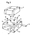
Fig.3 eine Mehrwegeventilkombination mit Adapterplatte; Darstellung der fluidischen Verknüpfung -
Fig.4 ein fluidisches Schaltbild der Mehrwegeventilkombination mit Fördereinrichtung -
Fig.5 ein fluidisches Schaltbild der Mehrwegeventilkombination ohne Fördereinrichtung -
Fig.6 eine elektrische Verbindung der beiden Spulen der Mehrwegeventilkombination - In
Fig.1 ist die Mehrwegeventilkombination aus den beiden identischen Ventilelementen dargestellt, die jeweils ein Fluidgehäuse (1A, 1B) und eine Spule (2A, 2B) enthält. Die Spule (2A, 2B) hat an ihrer Oberseite einen zylindrischen Ansatz (3A, 3B), auf den ein O-Ring (4) geschoben wird, der das jeweilige Fluidgehäuse (1A, 1 B) radial abdichtet. Die beiden Ventilelemente können ineinandergeschoben werden, wie ausFig.2 ersichtlich. Die Mehrwegeventilkombination (21) ist inFig.3 dargestellt. Diese kann einfach auf eine beliebige Adapterplatte montiert werden. - Die Spule (2A, 2B) besteht hauptsächlich aus der Wicklung (5), dem oberen Ventilsitz (6A, 6B), dem Kern (7A, 7B), der unteren Kernfeder (8A, 8B) und der Gehäusedichtung (9A, 9B).
- Durch die beiden Kanäle (10A, 10B) sind jeweils die oberen Ventilsitze (6A, 6B) und die Gehäusesitze (11A, 11B) miteinander verbunden. Mit den jeweiligen Kanälen (10A, 10B) sind die Anschlussbohrungen (12 bzw. 13) verbunden, die zu den dazugehörigen Anschlussstutzen (16, 19) in der Adapterplatte (32) führen. Die beiden Anschlussstutzen (16, 19) sind in einem Ausführungsbeispiel mit den beiden Anschlüssen der Pumpe (22A, 22B) verbunden.
- Mit dem Ventilraum (40A, 40B) sind ebenfalls Anschlussbohrungen (14 und 15) verbunden, die zu den Anschlussstutzen (18, 17) in der Adapterplatte (32) führen. Die Abdichtung erfolgt radial über O-Ringe (20).
- In die Adapterplatte (32) sind die Fluidbohrungen (23, 24) eingearbeitet. Hier können auch zwei Pumpenanschlüsse (22A, 22B) liegen.
- Die Verschaltung der Ventile ergibt sich aus
Fig.4 , wenn wie in einem Ausführungsbeispiel eine Förderungseinrichtung wie z.B. eine Pumpe verwendet wird. Durch Umschalten der beiden Ventile in der Mehrwegeventilkombination (21) wechselt die Durchströmrichtung in den beiden Anschlussleitungen (23, 24). - In
Fig.5 ist ein weiteres Ausführungsbeispiel ohne Fördereinrichtung dargestellt. -
Fig.6 zeigt die elektrische Verbindung der beiden Spulen (2A, 2B). Mit dem Klemmelement (25) werden die beiden Steckerfahnen (28A, 28B) elektrisch verbunden. Mit den Klemmelementen (26A, 26B) werden die beiden anderen Steckerfahnen (29A, 29B) jeweils zu einer Anschlussbuchse (27) geführt. Dadurch sind die beiden Spulen hintereinandergeschaltet. - Im folgenden wird die Funktionsweise der erfindungsgemäßen Vorrichtung erläutert.
- In einem ersten Ausführungsbeispiel steht das Medium am Einlass (14) der Mehrwegeventilkombination (21) an und gelangt in stromlosem Zustand durch den Ventilraum (40A) über den offenen Ventilsitz (6A) zum Anschluss (13), der mit dem saugseitigen Eingang einer Pumpe verbunden ist. Der Kern (7A) aus magnetischem Material, mit dem die Dichtkörper bzw. Dichtungen (31A, 30A) fest verbunden sind, verschließt mittels der Feder (8A) den Ventilsitz (11A) und somit gelangt kein Medium in den Kanal (10A). Im Kanal (10B) befindet sich Medium, das auf die Dichtung (31B) trifft. Der Kern (7B), mit dem die Dichtungen (31B, 30B) fest verbunden sind, verschließt mittels der Feder (8B) den Ventilsitz (11B), so dass kein Medium in den Ventilraum (40B) gelangt.
- Der druckseitige Ausgang der Pumpe ist mit dem Anschluss (12) verbunden. Von dort fliesst das Medium durch den geöffneten Ventilsitz (6B) und den Ventilraum (40B) in den Auslass (15). Somit fließt in stromlosem Zustand Medium vom Einlass (14) durch die Pumpe zum Auslass (15) durch die Mehrwegeventilkombination (21).
- Werden die beiden Ventile in der Mehrwegeventilkombination umgeschaltet, also die Spulen (2A und 2B) mit Strom beaufschlagt, so werden die beiden Kerne (7A und 7B) aus magnetischem Material angezogen und verschließen mittels der Dichtungen (30A und 30B), die mit den Enden der Kerne (7A und 7B) fest verbunden sind, die Ventilsitze (6A und 6B). Die beiden Ventilsitze (11A und 11B) werden geöffnet. Bei unveränderter Förderrichtung der Pumpe fließt das Medium jetzt vom Auslass (15) durch die Mehrwegeventilkombination (21) zum Einlass (14).
- Die Dichtungen können beispielsweise auf die Kerne anvulkanisiert sein. Eine andere Möglichkeit ist eine federnde Lagerung der Dichtungen in den Kernen.
Claims (10)
- Ventilkombination (21) zur Umkehrung der Strömungsrichtung eines Mediums umfassend zwei fluidisch miteinander verschaltete Mehrwegeventilmodule (1A, 2A; 1 B, 2B), dadurch gekennzeichnet, dass die beiden Ventilmodule (1A, 2A; 1B, 2B) identisch sind und jedes Ventilmodul aus einem quaderförmigen Ventilblock (2A, 2B) und einem plattenförmigen Verbindungsblock (1A, 1 B) besteht, der mit dem Ventilblock (2A, 2B) L-förmig zusammengesetzt ist, wobei die beiden Ventilmodule (1A, 2A; 1B, 2B) komplementär zusammengefügt sind und komplementäre Kupplungselemente aufweisen, mit denen die zusammengefügten Ventilmodule fluidisch miteinander verbunden sind, wobei die Ventilmodule (1A, 2A; 1B, 2B) relativ zueinander um zwei aufeinander senkrechte Achsen um 180° verdreht zusammengefügt sind.
- Ventilkombination (21) nach Anspruch 1, dadurch gekennzeichnet, dass im zusammengefügten Zustand die Ventilblöcke (2A, 2B) nebeneinander und zwischen den Verbindungsblöcken (1A, 1 B) angeordnet sind.
- Ventilkombination (21) nach Anspruch 1 oder 2, dadurch gekennzeichnet, dass jeder Ventilblock (2A, 2B) einen Antrieb mit einem beweglichen Kern (7A, 7B) aufweist, der an jeder seiner zwei voneinander abgewandten Stirnflächen einen Dichtkörper (30A, 31A; 30B, 31 B) trägt, der mit einem gegenüberliegenden Dichtsitz (6A, 11A; 6B, 11B) zusammenwirkt.
- Ventilkombination nach Anspruch 3, dadurch gekennzeichnet, dass jeweils einer der Dichtsitze (11A; 11B) in dem Verbindungsblock (1A; 1B) des anderen Ventilmoduls gebildet ist.
- Ventilkombination nach Anspruch 3 oder 4, dadurch gekennzeichnet, dass jeweils einer der Dichtsitze (6A; 6B) in dem Ventilblock (2A, 2B) gebildet ist und in Gegenüberlage zu dem Dichtsitz ein zylindrischer Ansatz (3A, 3B) am Ventilblock gebildet ist, der von einem am Ventilsitz mündenden Kanal durchsetzt und abgedichtet in eine passende Aussparung des gegenüberliegenden Verbindungsblocks (1A; 1 B) eingesetzt ist.
- Ventilkombination nach einem der Ansprüche 1 bis 5, dadurch gekennzeichnet, dass die elektrischen Antriebe der Ventilmodule in Reihe oder parallel geschaltet sind.
- Ventilkombination (21) nach einem der Ansprüche 1 bis 6, dadurch gekennzeichnet, dass jeder Verbindungsblock (1A, 1B) eine erste Anschlussbohrung (12; 13) aufweist, die mit einem Kanal (10A, 10B), über den die fluidische Verbindung zwischen den Ventilmodulen erfolgt, verbunden ist, sowie eine zweite Anschlussbohrung (14; 15) aufweist, die jeweils mit einem Ventilraum (40A, 40B) der Ventilblöcke (2A, 2B) verbunden ist, wobei die ersten und zweiten Anschlussbohrungen (12, 13, 14, 15) auf einer gemeinsamen Seite der Ventilkombination (21) angeordnet sind.
- Vorrichtung zur Umkehrung der Strömungsrichtung eines Mediums umfassend eine Ventilkombination (21) gemäß einem der Ansprüche 1 bis 7 sowie eine Adapterplatte (32), auf die die Ventilkombination (21) aufgesetzt ist.
- Vorrichtung gemäß Anspruch 8, wenn auf Anspruch 7 rückbezogen, wobei die Adapterplatte Anschlussstutzen (16, 17, 18, 19) aufweist, die zu den ersten und zweiten Anschlussbohrungen (12, 13, 14, 15) führen und mit diesen fluidisch dicht verbunden sind.
- Vorrichtung gemäß Anspruch 8 oder 9, dadurch gekennzeichnet, dass die beiden Ventile elektrisch über zwei Klemmelemente (26A, 26B) direkt mit den Anschlusskontakten einer an der Adapterplatte angebrachten Anschlussbuchse (27) verbunden sind.
Applications Claiming Priority (1)
| Application Number | Priority Date | Filing Date | Title |
|---|---|---|---|
| DE200620004749 DE202006004749U1 (de) | 2006-03-24 | 2006-03-24 | Vorrichtung und Ventilkombination zur Fließumkehr von strömenden Medien |
Publications (3)
| Publication Number | Publication Date |
|---|---|
| EP1837566A2 EP1837566A2 (de) | 2007-09-26 |
| EP1837566A3 EP1837566A3 (de) | 2010-06-23 |
| EP1837566B1 true EP1837566B1 (de) | 2012-05-02 |
Family
ID=36686860
Family Applications (1)
| Application Number | Title | Priority Date | Filing Date |
|---|---|---|---|
| EP20070005565 Ceased EP1837566B1 (de) | 2006-03-24 | 2007-03-19 | Vorrichtung und Ventilkombination zur Fliessumkehr von strömenden Medien |
Country Status (3)
| Country | Link |
|---|---|
| US (1) | US7721760B2 (de) |
| EP (1) | EP1837566B1 (de) |
| DE (1) | DE202006004749U1 (de) |
Families Citing this family (4)
| Publication number | Priority date | Publication date | Assignee | Title |
|---|---|---|---|---|
| EP3545221B1 (de) * | 2016-11-22 | 2025-09-17 | Parker-Hannifin Corporation | Extrem verschleppungsarmes magnetventil |
| CN111936102A (zh) * | 2017-09-07 | 2020-11-13 | 布鲁斯·穆里森 | 利用流体系统和致动器的装置 |
| EP3660335A1 (de) * | 2018-11-27 | 2020-06-03 | Berlin Heart GmbH | Schalteinheit und pneumatisches system |
| WO2025199043A1 (en) * | 2024-03-18 | 2025-09-25 | Iplexxus Holdings, Llc | Oscillating flow controller |
Family Cites Families (35)
| Publication number | Priority date | Publication date | Assignee | Title |
|---|---|---|---|---|
| US2553940A (en) * | 1946-03-07 | 1951-05-22 | Orpheus F Quartullo | Power steering apparatus |
| US2633871A (en) * | 1949-08-02 | 1953-04-07 | John B Parsons | Electromagnetic control valve device for fluid pressure systems or the like |
| US2821997A (en) * | 1954-03-15 | 1958-02-04 | Skinner Chuck Company | Solenoid control valve |
| GB842181A (en) * | 1957-10-04 | 1960-07-20 | Skinner Chuck Company | Solenoid-actuated fluid flow control valves |
| US3059621A (en) * | 1959-12-21 | 1962-10-23 | Erich Herion | Pressure control mechanism |
| US3002498A (en) * | 1960-02-04 | 1961-10-03 | Yale & Towne Mfg Co | Selector valve |
| US3215158A (en) * | 1963-10-09 | 1965-11-02 | Perfecting Service Company | Stack valve assemblies with interchangeable components |
| DE6910080U (de) | 1969-03-13 | 1973-02-22 | Ludwig Lehner | Umsteuerventil mit doppelkolben. |
| CH512701A (de) | 1969-08-28 | 1971-09-15 | Arnold Stucki Elektronikapp Ba | Heizwassersteuerungsorgan und Verfahren zum Betrieb desselben |
| US4108206A (en) * | 1976-08-30 | 1978-08-22 | Mountain Donald C | Hermetically sealed four-way valve |
| DE2646940A1 (de) * | 1976-10-18 | 1978-04-20 | Bieri Ag Liebefeld Liebefeld H | Elektromagnetisch betaetigtes hydraulisches wegeventil |
| US4355661A (en) * | 1978-09-28 | 1982-10-26 | The Bendix Corporation | Dual solenoid vacuum modulator |
| US4285363A (en) * | 1979-11-05 | 1981-08-25 | Hydraulic Servocontrols Corporation | Control valve construction |
| DE3006259A1 (de) * | 1980-02-20 | 1981-08-27 | Wabco Fahrzeugbremsen Gmbh, 3000 Hannover | Wechselventil fuer pneumatisch gesteuerte tueranlgen |
| DE3122961A1 (de) * | 1981-06-10 | 1982-12-30 | Bochumer Eisenhütte Heintzmann GmbH & Co, 4630 Bochum | Elektro-hydraulisches wegeventil |
| US4539961A (en) * | 1982-08-23 | 1985-09-10 | General Motors Corporation | Fuel rail |
| US4617952A (en) * | 1984-07-31 | 1986-10-21 | Yamatake-Honeywell Co. Limited | Switching valve and an electro-pneumatic pressure converter utilizing the same |
| US4848393A (en) * | 1986-06-27 | 1989-07-18 | West Robert E | Fault tolerant fluid flow apparatus |
| WO1989005746A1 (fr) * | 1987-12-14 | 1989-06-29 | Alfred Teves Gmbh | Ensemble d'appareils de distribution et de regulation groupes |
| US4842016A (en) * | 1988-02-22 | 1989-06-27 | Delta Projects Inc. | Switching valve |
| GB8810873D0 (en) * | 1988-05-07 | 1988-06-08 | Penlon Ltd | Anaesthesia equipment |
| US4913189A (en) * | 1989-03-17 | 1990-04-03 | Colt Industries Inc. | Climate control system control module |
| DE4037353C1 (de) * | 1990-11-20 | 1992-03-12 | Mannesmann Ag, 4000 Duesseldorf, De | |
| DE4309695A1 (de) * | 1993-03-25 | 1994-09-29 | Festo Kg | Steuereinrichtung für ein Mehrwegeventil |
| JP3676499B2 (ja) * | 1996-05-28 | 2005-07-27 | Smc株式会社 | スイッチ機構付き電磁弁マニホールド |
| US5992463A (en) * | 1996-10-30 | 1999-11-30 | Unit Instruments, Inc. | Gas panel |
| DE29703788U1 (de) * | 1997-03-03 | 1997-06-26 | Bürkert Werke GmbH & Co., 74653 Ingelfingen | Modularer Steuerblock für die Analysentechnik |
| DE19733577B4 (de) * | 1997-08-02 | 2006-04-13 | Pierburg Gmbh | Elektrisches Umschaltventil |
| DE29822959U1 (de) * | 1998-12-23 | 1999-05-12 | Bürkert Werke GmbH & Co., 74653 Ingelfingen | Steuerelement für Fluid |
| EP1071897A1 (de) | 1999-02-20 | 2001-01-31 | BERKENBUSCH, Stefan | Armatur zur umkehr der strömungsrichtung eines mediums |
| DE10009117B4 (de) * | 2000-02-26 | 2009-07-30 | Wabco Gmbh | Konstruktion eines Bremsdruckmodulators für Anhänger mit elektronischer Bremsanlage |
| DE20009234U1 (de) * | 2000-05-23 | 2000-08-24 | Bürkert Werke GmbH & Co., 74653 Ingelfingen | Fluidisches Anschlusssystem |
| JP2003240140A (ja) * | 2002-02-21 | 2003-08-27 | Tgk Co Ltd | 四方向切換弁 |
| US7247778B2 (en) * | 2003-08-29 | 2007-07-24 | Spencer Chase | Addressable pneumatic valve system |
| US7261121B2 (en) * | 2005-03-29 | 2007-08-28 | Norgren, Inc. | Expandable gas or fluid distribution system |
-
2006
- 2006-03-24 DE DE200620004749 patent/DE202006004749U1/de not_active Expired - Lifetime
-
2007
- 2007-03-19 EP EP20070005565 patent/EP1837566B1/de not_active Ceased
- 2007-03-19 US US11/725,298 patent/US7721760B2/en not_active Expired - Fee Related
Also Published As
| Publication number | Publication date |
|---|---|
| US20070235093A1 (en) | 2007-10-11 |
| US7721760B2 (en) | 2010-05-25 |
| DE202006004749U1 (de) | 2006-06-29 |
| EP1837566A2 (de) | 2007-09-26 |
| EP1837566A3 (de) | 2010-06-23 |
Similar Documents
| Publication | Publication Date | Title |
|---|---|---|
| US20190368621A1 (en) | Multi-channel disc valve assembly | |
| EP1810764A1 (de) | Verfahren zum Herstellen von Ventilgehäusen und Ventilgehäuse | |
| EP3215743B1 (de) | Verdrängerpumpe | |
| DE102014006511A1 (de) | Ventilanordnung | |
| EP1837566A2 (de) | Vorrichtung und Ventilkombination zur Fliessumkehr von strömenden Medien | |
| DE102009014050A1 (de) | Wärmemanagementmodul mit axial hydraulisch betriebenem Ventilglied | |
| EP0633415A1 (de) | Elektromagnetisches Umschaltventil | |
| DE102012010986A1 (de) | Elektrohydraulisches Vorsteuerventil | |
| DE4419875B4 (de) | Elektromagnetisches Umschaltventil | |
| EP2584230B1 (de) | Ventil, hydraulische Anordnung mit einem derartigen Ventil und Verwendung eines Tasters oder Schalters für ein Ventil | |
| DE112020000079T5 (de) | Elektromagnetisches vorsteuerventil | |
| DE102015207033A1 (de) | Tragbare mobile Hydraulikpumpe für hydraulisch zu betreibende Werkzeuge | |
| EP1731809B1 (de) | Schaltvorrichtung für Mehrfachbehandlungsvorrichtungen | |
| WO2016012083A1 (de) | Schraubenverdichter | |
| EP1853839B1 (de) | Bausatz und wegeventilserie | |
| EP1526288A1 (de) | Pneumatische Ventilanordnung mit einem Kanaltrennelement | |
| DE102012018451A1 (de) | Wegeventil mit einer Mehrzahl kugelförmiger Dichtelemente | |
| EP2557343A2 (de) | Elektromagnetventil | |
| EP3337978B1 (de) | Motorpumpenaggregat | |
| EP1537323B1 (de) | Aggregat zum fördern von kraftstoff aus einem kraftstofftank zur brennkraftmaschine eines kraftfahrzeuges | |
| DE102021107891B4 (de) | 3/2-Wegeventil | |
| DE102012107725A1 (de) | Ventilvorrichtung für einen Hydraulikkreislauf sowie Ölpumpenregelanordnung | |
| DE102009017876B3 (de) | Ventileinrichtung | |
| DE10007105A1 (de) | Elektrisch-Hydraulische Schnittstelle | |
| DE102023211499A1 (de) | Fluidpumpenventil |
Legal Events
| Date | Code | Title | Description |
|---|---|---|---|
| PUAI | Public reference made under article 153(3) epc to a published international application that has entered the european phase |
Free format text: ORIGINAL CODE: 0009012 |
|
| AK | Designated contracting states |
Kind code of ref document: A2 Designated state(s): AT BE BG CH CY CZ DE DK EE ES FI FR GB GR HU IE IS IT LI LT LU LV MC MT NL PL PT RO SE SI SK TR |
|
| AX | Request for extension of the european patent |
Extension state: AL BA HR MK YU |
|
| RAP1 | Party data changed (applicant data changed or rights of an application transferred) |
Owner name: BUERKERT WERKE GMBH |
|
| PUAL | Search report despatched |
Free format text: ORIGINAL CODE: 0009013 |
|
| AK | Designated contracting states |
Kind code of ref document: A3 Designated state(s): AT BE BG CH CY CZ DE DK EE ES FI FR GB GR HU IE IS IT LI LT LU LV MC MT NL PL PT RO SE SI SK TR |
|
| AX | Request for extension of the european patent |
Extension state: AL BA HR MK RS |
|
| RIC1 | Information provided on ipc code assigned before grant |
Ipc: F15B 11/00 20060101ALN20070703BHEP Ipc: F16K 11/22 20060101AFI20070703BHEP Ipc: F15B 13/08 20060101ALI20100518BHEP Ipc: F16K 31/06 20060101ALI20100518BHEP |
|
| 17P | Request for examination filed |
Effective date: 20101213 |
|
| AKX | Designation fees paid |
Designated state(s): DE |
|
| GRAP | Despatch of communication of intention to grant a patent |
Free format text: ORIGINAL CODE: EPIDOSNIGR1 |
|
| RIC1 | Information provided on ipc code assigned before grant |
Ipc: F15B 13/08 20060101ALI20111005BHEP Ipc: F15B 11/00 20060101ALN20111005BHEP Ipc: F16K 31/06 20060101ALI20111005BHEP Ipc: F16K 11/22 20060101AFI20111005BHEP |
|
| RIC1 | Information provided on ipc code assigned before grant |
Ipc: F16K 11/22 20060101AFI20111013BHEP Ipc: F16K 31/06 20060101ALI20111013BHEP Ipc: F15B 11/00 20060101ALN20111013BHEP Ipc: F15B 13/08 20060101ALI20111013BHEP |
|
| GRAS | Grant fee paid |
Free format text: ORIGINAL CODE: EPIDOSNIGR3 |
|
| GRAA | (expected) grant |
Free format text: ORIGINAL CODE: 0009210 |
|
| AK | Designated contracting states |
Kind code of ref document: B1 Designated state(s): DE |
|
| REG | Reference to a national code |
Ref country code: DE Ref legal event code: R096 Ref document number: 502007009795 Country of ref document: DE Effective date: 20120705 |
|
| PLBE | No opposition filed within time limit |
Free format text: ORIGINAL CODE: 0009261 |
|
| STAA | Information on the status of an ep patent application or granted ep patent |
Free format text: STATUS: NO OPPOSITION FILED WITHIN TIME LIMIT |
|
| 26N | No opposition filed |
Effective date: 20130205 |
|
| REG | Reference to a national code |
Ref country code: DE Ref legal event code: R097 Ref document number: 502007009795 Country of ref document: DE Effective date: 20130205 |
|
| PGFP | Annual fee paid to national office [announced via postgrant information from national office to epo] |
Ref country code: DE Payment date: 20190326 Year of fee payment: 13 |
|
| PGFP | Annual fee paid to national office [announced via postgrant information from national office to epo] |
Ref country code: DE Payment date: 20190326 Year of fee payment: 13 |
|
| REG | Reference to a national code |
Ref country code: DE Ref legal event code: R119 Ref document number: 502007009795 Country of ref document: DE |
|
| PG25 | Lapsed in a contracting state [announced via postgrant information from national office to epo] |
Ref country code: DE Free format text: LAPSE BECAUSE OF NON-PAYMENT OF DUE FEES Effective date: 20201001 |
|
| P01 | Opt-out of the competence of the unified patent court (upc) registered |
Effective date: 20230523 |