EP1837494A2 - Abgasreinigungssystem - Google Patents
Abgasreinigungssystem Download PDFInfo
- Publication number
- EP1837494A2 EP1837494A2 EP07251151A EP07251151A EP1837494A2 EP 1837494 A2 EP1837494 A2 EP 1837494A2 EP 07251151 A EP07251151 A EP 07251151A EP 07251151 A EP07251151 A EP 07251151A EP 1837494 A2 EP1837494 A2 EP 1837494A2
- Authority
- EP
- European Patent Office
- Prior art keywords
- exhaust gas
- nox
- catalyst
- purifying
- partition wall
- Prior art date
- Legal status (The legal status is an assumption and is not a legal conclusion. Google has not performed a legal analysis and makes no representation as to the accuracy of the status listed.)
- Granted
Links
Images


Classifications
-
- F—MECHANICAL ENGINEERING; LIGHTING; HEATING; WEAPONS; BLASTING
- F01—MACHINES OR ENGINES IN GENERAL; ENGINE PLANTS IN GENERAL; STEAM ENGINES
- F01N—GAS-FLOW SILENCERS OR EXHAUST APPARATUS FOR MACHINES OR ENGINES IN GENERAL; GAS-FLOW SILENCERS OR EXHAUST APPARATUS FOR INTERNAL COMBUSTION ENGINES
- F01N3/00—Exhaust or silencing apparatus having means for purifying, rendering innocuous, or otherwise treating exhaust
- F01N3/02—Exhaust or silencing apparatus having means for purifying, rendering innocuous, or otherwise treating exhaust for cooling, or for removing solid constituents of, exhaust
- F01N3/021—Exhaust or silencing apparatus having means for purifying, rendering innocuous, or otherwise treating exhaust for cooling, or for removing solid constituents of, exhaust by means of filters
- F01N3/022—Exhaust or silencing apparatus having means for purifying, rendering innocuous, or otherwise treating exhaust for cooling, or for removing solid constituents of, exhaust by means of filters characterised by specially adapted filtering structure, e.g. honeycomb, mesh or fibrous
- F01N3/0222—Exhaust or silencing apparatus having means for purifying, rendering innocuous, or otherwise treating exhaust for cooling, or for removing solid constituents of, exhaust by means of filters characterised by specially adapted filtering structure, e.g. honeycomb, mesh or fibrous the structure being monolithic, e.g. honeycombs
-
- F—MECHANICAL ENGINEERING; LIGHTING; HEATING; WEAPONS; BLASTING
- F01—MACHINES OR ENGINES IN GENERAL; ENGINE PLANTS IN GENERAL; STEAM ENGINES
- F01N—GAS-FLOW SILENCERS OR EXHAUST APPARATUS FOR MACHINES OR ENGINES IN GENERAL; GAS-FLOW SILENCERS OR EXHAUST APPARATUS FOR INTERNAL COMBUSTION ENGINES
- F01N13/00—Exhaust or silencing apparatus characterised by constructional features ; Exhaust or silencing apparatus, or parts thereof, having pertinent characteristics not provided for in, or of interest apart from, groups F01N1/00 - F01N5/00, F01N9/00, F01N11/00
- F01N13/009—Exhaust or silencing apparatus characterised by constructional features ; Exhaust or silencing apparatus, or parts thereof, having pertinent characteristics not provided for in, or of interest apart from, groups F01N1/00 - F01N5/00, F01N9/00, F01N11/00 having two or more separate purifying devices arranged in series
-
- F—MECHANICAL ENGINEERING; LIGHTING; HEATING; WEAPONS; BLASTING
- F01—MACHINES OR ENGINES IN GENERAL; ENGINE PLANTS IN GENERAL; STEAM ENGINES
- F01N—GAS-FLOW SILENCERS OR EXHAUST APPARATUS FOR MACHINES OR ENGINES IN GENERAL; GAS-FLOW SILENCERS OR EXHAUST APPARATUS FOR INTERNAL COMBUSTION ENGINES
- F01N3/00—Exhaust or silencing apparatus having means for purifying, rendering innocuous, or otherwise treating exhaust
- F01N3/02—Exhaust or silencing apparatus having means for purifying, rendering innocuous, or otherwise treating exhaust for cooling, or for removing solid constituents of, exhaust
- F01N3/021—Exhaust or silencing apparatus having means for purifying, rendering innocuous, or otherwise treating exhaust for cooling, or for removing solid constituents of, exhaust by means of filters
- F01N3/023—Exhaust or silencing apparatus having means for purifying, rendering innocuous, or otherwise treating exhaust for cooling, or for removing solid constituents of, exhaust by means of filters using means for regenerating the filters, e.g. by burning trapped particles
- F01N3/0231—Exhaust or silencing apparatus having means for purifying, rendering innocuous, or otherwise treating exhaust for cooling, or for removing solid constituents of, exhaust by means of filters using means for regenerating the filters, e.g. by burning trapped particles using special exhaust apparatus upstream of the filter for producing nitrogen dioxide, e.g. for continuous filter regeneration systems [CRT]
-
- F—MECHANICAL ENGINEERING; LIGHTING; HEATING; WEAPONS; BLASTING
- F01—MACHINES OR ENGINES IN GENERAL; ENGINE PLANTS IN GENERAL; STEAM ENGINES
- F01N—GAS-FLOW SILENCERS OR EXHAUST APPARATUS FOR MACHINES OR ENGINES IN GENERAL; GAS-FLOW SILENCERS OR EXHAUST APPARATUS FOR INTERNAL COMBUSTION ENGINES
- F01N3/00—Exhaust or silencing apparatus having means for purifying, rendering innocuous, or otherwise treating exhaust
- F01N3/02—Exhaust or silencing apparatus having means for purifying, rendering innocuous, or otherwise treating exhaust for cooling, or for removing solid constituents of, exhaust
- F01N3/021—Exhaust or silencing apparatus having means for purifying, rendering innocuous, or otherwise treating exhaust for cooling, or for removing solid constituents of, exhaust by means of filters
- F01N3/033—Exhaust or silencing apparatus having means for purifying, rendering innocuous, or otherwise treating exhaust for cooling, or for removing solid constituents of, exhaust by means of filters in combination with other devices
- F01N3/035—Exhaust or silencing apparatus having means for purifying, rendering innocuous, or otherwise treating exhaust for cooling, or for removing solid constituents of, exhaust by means of filters in combination with other devices with catalytic reactors, e.g. catalysed diesel particulate filters
-
- F—MECHANICAL ENGINEERING; LIGHTING; HEATING; WEAPONS; BLASTING
- F01—MACHINES OR ENGINES IN GENERAL; ENGINE PLANTS IN GENERAL; STEAM ENGINES
- F01N—GAS-FLOW SILENCERS OR EXHAUST APPARATUS FOR MACHINES OR ENGINES IN GENERAL; GAS-FLOW SILENCERS OR EXHAUST APPARATUS FOR INTERNAL COMBUSTION ENGINES
- F01N3/00—Exhaust or silencing apparatus having means for purifying, rendering innocuous, or otherwise treating exhaust
- F01N3/08—Exhaust or silencing apparatus having means for purifying, rendering innocuous, or otherwise treating exhaust for rendering innocuous
- F01N3/0807—Exhaust or silencing apparatus having means for purifying, rendering innocuous, or otherwise treating exhaust for rendering innocuous by using absorbents or adsorbents
- F01N3/0821—Exhaust or silencing apparatus having means for purifying, rendering innocuous, or otherwise treating exhaust for rendering innocuous by using absorbents or adsorbents combined with particulate filters
-
- F—MECHANICAL ENGINEERING; LIGHTING; HEATING; WEAPONS; BLASTING
- F01—MACHINES OR ENGINES IN GENERAL; ENGINE PLANTS IN GENERAL; STEAM ENGINES
- F01N—GAS-FLOW SILENCERS OR EXHAUST APPARATUS FOR MACHINES OR ENGINES IN GENERAL; GAS-FLOW SILENCERS OR EXHAUST APPARATUS FOR INTERNAL COMBUSTION ENGINES
- F01N3/00—Exhaust or silencing apparatus having means for purifying, rendering innocuous, or otherwise treating exhaust
- F01N3/08—Exhaust or silencing apparatus having means for purifying, rendering innocuous, or otherwise treating exhaust for rendering innocuous
- F01N3/0807—Exhaust or silencing apparatus having means for purifying, rendering innocuous, or otherwise treating exhaust for rendering innocuous by using absorbents or adsorbents
- F01N3/0828—Exhaust or silencing apparatus having means for purifying, rendering innocuous, or otherwise treating exhaust for rendering innocuous by using absorbents or adsorbents characterised by the absorbed or adsorbed substances
- F01N3/0842—Nitrogen oxides
-
- F—MECHANICAL ENGINEERING; LIGHTING; HEATING; WEAPONS; BLASTING
- F01—MACHINES OR ENGINES IN GENERAL; ENGINE PLANTS IN GENERAL; STEAM ENGINES
- F01N—GAS-FLOW SILENCERS OR EXHAUST APPARATUS FOR MACHINES OR ENGINES IN GENERAL; GAS-FLOW SILENCERS OR EXHAUST APPARATUS FOR INTERNAL COMBUSTION ENGINES
- F01N3/00—Exhaust or silencing apparatus having means for purifying, rendering innocuous, or otherwise treating exhaust
- F01N3/08—Exhaust or silencing apparatus having means for purifying, rendering innocuous, or otherwise treating exhaust for rendering innocuous
- F01N3/10—Exhaust or silencing apparatus having means for purifying, rendering innocuous, or otherwise treating exhaust for rendering innocuous by thermal or catalytic conversion of noxious components of exhaust
- F01N3/18—Exhaust or silencing apparatus having means for purifying, rendering innocuous, or otherwise treating exhaust for rendering innocuous by thermal or catalytic conversion of noxious components of exhaust characterised by methods of operation; Control
- F01N3/20—Exhaust or silencing apparatus having means for purifying, rendering innocuous, or otherwise treating exhaust for rendering innocuous by thermal or catalytic conversion of noxious components of exhaust characterised by methods of operation; Control specially adapted for catalytic conversion ; Methods of operation or control of catalytic converters
- F01N3/206—Adding periodically or continuously substances to exhaust gases for promoting purification, e.g. catalytic material in liquid form, NOx reducing agents
-
- F—MECHANICAL ENGINEERING; LIGHTING; HEATING; WEAPONS; BLASTING
- F01—MACHINES OR ENGINES IN GENERAL; ENGINE PLANTS IN GENERAL; STEAM ENGINES
- F01N—GAS-FLOW SILENCERS OR EXHAUST APPARATUS FOR MACHINES OR ENGINES IN GENERAL; GAS-FLOW SILENCERS OR EXHAUST APPARATUS FOR INTERNAL COMBUSTION ENGINES
- F01N3/00—Exhaust or silencing apparatus having means for purifying, rendering innocuous, or otherwise treating exhaust
- F01N3/08—Exhaust or silencing apparatus having means for purifying, rendering innocuous, or otherwise treating exhaust for rendering innocuous
- F01N3/10—Exhaust or silencing apparatus having means for purifying, rendering innocuous, or otherwise treating exhaust for rendering innocuous by thermal or catalytic conversion of noxious components of exhaust
- F01N3/18—Exhaust or silencing apparatus having means for purifying, rendering innocuous, or otherwise treating exhaust for rendering innocuous by thermal or catalytic conversion of noxious components of exhaust characterised by methods of operation; Control
- F01N3/20—Exhaust or silencing apparatus having means for purifying, rendering innocuous, or otherwise treating exhaust for rendering innocuous by thermal or catalytic conversion of noxious components of exhaust characterised by methods of operation; Control specially adapted for catalytic conversion ; Methods of operation or control of catalytic converters
- F01N3/2066—Selective catalytic reduction [SCR]
-
- F—MECHANICAL ENGINEERING; LIGHTING; HEATING; WEAPONS; BLASTING
- F01—MACHINES OR ENGINES IN GENERAL; ENGINE PLANTS IN GENERAL; STEAM ENGINES
- F01N—GAS-FLOW SILENCERS OR EXHAUST APPARATUS FOR MACHINES OR ENGINES IN GENERAL; GAS-FLOW SILENCERS OR EXHAUST APPARATUS FOR INTERNAL COMBUSTION ENGINES
- F01N2330/00—Structure of catalyst support or particle filter
- F01N2330/06—Ceramic, e.g. monoliths
-
- F—MECHANICAL ENGINEERING; LIGHTING; HEATING; WEAPONS; BLASTING
- F01—MACHINES OR ENGINES IN GENERAL; ENGINE PLANTS IN GENERAL; STEAM ENGINES
- F01N—GAS-FLOW SILENCERS OR EXHAUST APPARATUS FOR MACHINES OR ENGINES IN GENERAL; GAS-FLOW SILENCERS OR EXHAUST APPARATUS FOR INTERNAL COMBUSTION ENGINES
- F01N2330/00—Structure of catalyst support or particle filter
- F01N2330/30—Honeycomb supports characterised by their structural details
- F01N2330/48—Honeycomb supports characterised by their structural details characterised by the number of flow passages, e.g. cell density
-
- F—MECHANICAL ENGINEERING; LIGHTING; HEATING; WEAPONS; BLASTING
- F01—MACHINES OR ENGINES IN GENERAL; ENGINE PLANTS IN GENERAL; STEAM ENGINES
- F01N—GAS-FLOW SILENCERS OR EXHAUST APPARATUS FOR MACHINES OR ENGINES IN GENERAL; GAS-FLOW SILENCERS OR EXHAUST APPARATUS FOR INTERNAL COMBUSTION ENGINES
- F01N2340/00—Dimensional characteristics of the exhaust system, e.g. length, diameter or volume of the apparatus; Spatial arrangements of exhaust apparatuses
- F01N2340/02—Dimensional characteristics of the exhaust system, e.g. length, diameter or volume of the apparatus; Spatial arrangements of exhaust apparatuses characterised by the distance of the apparatus to the engine, or the distance between two exhaust treating apparatuses
-
- F—MECHANICAL ENGINEERING; LIGHTING; HEATING; WEAPONS; BLASTING
- F01—MACHINES OR ENGINES IN GENERAL; ENGINE PLANTS IN GENERAL; STEAM ENGINES
- F01N—GAS-FLOW SILENCERS OR EXHAUST APPARATUS FOR MACHINES OR ENGINES IN GENERAL; GAS-FLOW SILENCERS OR EXHAUST APPARATUS FOR INTERNAL COMBUSTION ENGINES
- F01N2370/00—Selection of materials for exhaust purification
- F01N2370/02—Selection of materials for exhaust purification used in catalytic reactors
-
- F—MECHANICAL ENGINEERING; LIGHTING; HEATING; WEAPONS; BLASTING
- F01—MACHINES OR ENGINES IN GENERAL; ENGINE PLANTS IN GENERAL; STEAM ENGINES
- F01N—GAS-FLOW SILENCERS OR EXHAUST APPARATUS FOR MACHINES OR ENGINES IN GENERAL; GAS-FLOW SILENCERS OR EXHAUST APPARATUS FOR INTERNAL COMBUSTION ENGINES
- F01N2510/00—Surface coverings
- F01N2510/06—Surface coverings for exhaust purification, e.g. catalytic reaction
-
- F—MECHANICAL ENGINEERING; LIGHTING; HEATING; WEAPONS; BLASTING
- F01—MACHINES OR ENGINES IN GENERAL; ENGINE PLANTS IN GENERAL; STEAM ENGINES
- F01N—GAS-FLOW SILENCERS OR EXHAUST APPARATUS FOR MACHINES OR ENGINES IN GENERAL; GAS-FLOW SILENCERS OR EXHAUST APPARATUS FOR INTERNAL COMBUSTION ENGINES
- F01N2610/00—Adding substances to exhaust gases
- F01N2610/02—Adding substances to exhaust gases the substance being ammonia or urea
-
- Y—GENERAL TAGGING OF NEW TECHNOLOGICAL DEVELOPMENTS; GENERAL TAGGING OF CROSS-SECTIONAL TECHNOLOGIES SPANNING OVER SEVERAL SECTIONS OF THE IPC; TECHNICAL SUBJECTS COVERED BY FORMER USPC CROSS-REFERENCE ART COLLECTIONS [XRACs] AND DIGESTS
- Y02—TECHNOLOGIES OR APPLICATIONS FOR MITIGATION OR ADAPTATION AGAINST CLIMATE CHANGE
- Y02T—CLIMATE CHANGE MITIGATION TECHNOLOGIES RELATED TO TRANSPORTATION
- Y02T10/00—Road transport of goods or passengers
- Y02T10/10—Internal combustion engine [ICE] based vehicles
- Y02T10/12—Improving ICE efficiencies
Definitions
- the present invention relates to an exhaust gas purifying system suited for use in purification of components to be purified such as nitrogen oxides (NOx) and microparticles (PM) contained in exhaust gas discharged from a diesel engine for automobile.
- NOx nitrogen oxides
- PM microparticles
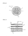
- honeycomb catalytic members For cleaning NOx contained in exhaust gas discharged from diesel engines of automobiles and the like, catalytic members having honeycomb structure (honeycomb catalytic members) are currently used. These honeycomb catalytic members have such a structure that a catalytic layer 15 is carried on surface of a partition wall 4 forming a cell 3 as shown in Fig. 8. As shown in Fig. 9, in cleaning exhaust gas using this honeycomb catalytic member 60 (honeycomb structure member 11), exhaust gas is caused to flow into the cell 3 of the honeycomb catalytic member 60 from the side of one end face 2a, and to come into contact with a catalytic layer (not shown) on surface of the partition wall 4, and then to flow outside from the side of the other end face 2b (see, Patent document 1, for example).
- transmissibility of components to be purified from exhaust gas to a catalytic layer on surface of partition wall increases in inverse proportion to square of hydraulic diameter of cell. Therefore, the higher the cell density, the better the transmissibility of components to be purified is.
- pressure loss also tends to increase in inverse proportion to square of hydraulic diameter of cell. Therefore, improvement in transmissibility of components to be purified is accompanied with the problem of increased pressure loss.
- Thickness of a catalytic layer on surface or partition wall is typically about several tens micrometers.
- the purifying efficiency of the honeycomb catalytic member tends to decrease. This tendency is particularly significant in a low-temperature condition. Therefore, in order to increase the purifying efficiency of exhaust gas, it is necessary to increase the diffusing speed of the components to be purified in the catalytic layer not only by increasing surface area of catalytic layer, but also by reducing the thickness of the catalytic layer. Increasing the cell density still poses the problem of increase in pressure loss although it advantageously increases surface area of catalytic layer.
- the present invention has been devised in consideration of the problems of conventional art as described above, and it is an object of the present invention to provide an exhaust gas purifying system which achieves excellent purifying efficiency of NOx contained in exhaust gas discharged from a diesel engine, and low pressure loss, and may be mounted in limited space.
- Inventors of the present invention made diligent efforts for achieving the above object, and found that the above object can be achieved by arranging in an exhaust gas flow path, a honeycomb filter, and a NOx purifying catalytic member having substantially the same shape as the honeycomb filter and carrying NOx purifying catalyst at a certain position, in this order, and finally accomplished the present invention.
- An exhaust gas purifying system comprising:
- NOx purifying catalyst is a NOx selective reducing SCR containing at least one selected from the group consisting of vanadium, titania, tungsten oxide, silver and alumina, or a NOx occluding catalyst containing alkaline metal and/or alkaline earth metal.
- honeycomb filter and/or the honeycomb catalyst carrier is formed of at least one ceramics selected from the group consisting of silicon carbide, cordierite, alumina titanate, Sialon, mullite, silicon nitride, zirconium phosphate, zirconia, titania, alumina and silica.
- honeycomb catalyst carrier is formed with a plurality of penetrating cells which communicate between the two end faces and lack the plugging portion by provision of the partition wall, and proportion of number of penetrating cells, relative to the sum of plugged cells in which the plugging portion is placed and the penetrating cells is 10% or more.
- the exhaust gas purifying system of the present invention presents advantages of excellent purifying efficiency of NOx contained in exhaust gas discharged from diesel engines and small pressure loss, and mountability in limited space.
- Fig. 1 is a section view schematically showing one embodiment of the exhaust gas purifying system of the present invention.
- an exhaust gas purifying system 10 of the present invention has a honeycomb filter 1, and a NOx purifying catalytic member 32.
- DPF diesel particulate filter
- DPF generally includes a porous partition wall having a number of pores, which is arranged so that a plurality of cells communicating between two end faces are formed, and a plugging portion disposed either end face or inside a cell for plugging the cell.
- the honeycomb filter constituting the exhaust gas purifying system according to the present embodiment is not particularly limited in terms of its size, porosity and pore size of partition wall, and arrangement pattern of plugging portion, and may be implemented by a honeycomb filter whish is applicable as commonly used DPF. Therefore, cell density of a honeycomb filter is typically, 7.8 to 62 cells/cm 2 (50 to 400 cpsi), and preferably 5.5 to 47 cells/cm 2 (100 to 300 cpsi).
- the notation "cpsi” is abbreviation for "cells per square inch", and is a unit representing number of cells per square inch. 10 cpsi corresponds to about 1.55 cells/cm 2 .
- Thickness of partition wall of the honeycomb filter is typically 0.254 to 0.508 mm (10 to 20 mil), and preferably 0.305 to 0.432mm (12 to 17 mil). 1 mil corresponds to thousandth of 1 inch, and is about 0.025mm.
- Mean pore size of partition wall of the honeycomb filter is typically 10 to 80 ⁇ m, and preferably 25 to 68 ⁇ m.
- Mean Pore size used herein is a property value determined by a mercury porosimeter.
- Porosity of partition wall of honeycomb filter is typically 30 to 70%, and preferably 45 to 65%.
- the NOx purifying catalytic member 32 shown in Fig. 1 includes a honeycomb catalyst carrier having substantially same shape as the above honeycomb filter 1, and a NOx purifying catalyst carried on surface of partition wall of the honeycomb catalyst carrier and/or surface of pores.
- substantially the same shape as honeycomb filter used herein means that a porous partition wall having a number of pores, which is arranged so that a plurality of cells communicating between two end faces are formed, and a plugging portion disposed either end face or inside a cell for plugging the cell are provided. Therefore, sizes of the entirety and individual structures, porosity and pore size of partition wall, arrangement pattern of plugging portion and the like may not be necessary identical.
- Fig. 7 is a section view schematically showing one example of a NOx purifying catalytic member.
- the NOx purifying catalytic member 32 employed in the exhaust gas purifying system of the present embodiment has a honeycomb catalyst carrier 55 and a NOx purifying catalyst 21.
- the honeycomb catalyst carrier 55 includes a porous partition wall 14 having a number of pores, which is arranged so that a plurality of cells 13 communicating between two end faces are formed, and a plugging portion 17 disposed either end face, or inside a cell for plugging the cell 13.
- the plugging portion 17 may not be necessarily disposed on end face of the cell 13, and may be disposed inside the cell 13.
- Density of cells 13 (cell density) of the honeycomb catalyst carrier 55 is preferably 12.4 to 93.0 cells/cm 2 (80 to 600 cpsi), more preferably 15.5 to 46.5 cells/cm 2 (100 to 300 cpsi), and particularly preferably 15.5 to 31.0 cells/cm 2 (100 to 200 cpsi). If the cell density is less than 12.4 cells/cm 2 , contact efficiency with exhaust gas tends to be insufficient. On the other hand, if the cell density is more than 93.0 cells/cm 2 , pressure loss tends to increase.
- Thickness of partition wall 14 is preferably 0.1 to 0.508 mm (4 to 20 mil), more preferably 0.254 to 0.457mm (10 to 18 mil), and particularly preferably 0.305 to 0.457mm (12 to 18 mil).
- thickness of the partition wall 14 is less than 0.1 mm, strength is insufficient and thermal shock resistance may decrease.
- thickness of the wall 14 is more than 0.508, pressure loss tends to increase.
- the NOx purifying catalyst 21 is a catalyst capable of cleaning nitrogen oxides (NOx) contained in exhaust gas discharged from a diesel engine.
- Preferred examples of the NOx purifying catalyst 21 include NOx selective reducing SCR catalysts (hereinafter, simply referred to as "SCR catalyst") containing at least one selected from the group consisting of vanadium, titania, tungsten oxide, silver and alumina, and NOx occluding catalysts containing alkaline metal and/or alkaline earth metal.
- SCR catalyst NOx selective reducing SCR catalysts
- K, Na and Li can be exemplified.
- Ca can be exemplified.
- the total amount of K, Na, Li and Ca is preferably 5 g or more per one litter of volume of honeycomb catalyst carrier.
- Mean pore size of partition wall of the NOx purifying catalytic member is preferably 20 to 70 ⁇ m, more preferably 30 to 70 ⁇ m, and particularly preferably 40 to 65 ⁇ m. If the mean pore size is less than 20 ⁇ m, pressure loss tends to increase. On the other hand, if the mean pore size is more than 65 ⁇ m, sufficient contact area between exhaust gas and catalyst layer tends to be difficult to be ensured.
- Porosity of partition wall of the NOx purifying catalytic member is preferably 40 to 70%, and more preferably 45 to 65%. If the porosity is less than 40%, passing speed through the partition wall increases, and cleaning performance tends to be impaired. On the other hand, if the porosity is more than 70%, strength tends to be insufficient.
- common logarithm standard deviation ⁇ of pore size distribution of partition wall of the NOx purifying catalytic member is 0.1 to 0.6
- Common logarithm standard deviation ⁇ of pore size distribution is more preferably 0.2 to 0.4, and particularly preferably 0.3 to 0.4.
- Exhaust gas having flown into a cell 13 from one end face of the NOx purifying catalytic member 32 passes through the partition wall 14 while being in contact with the NOx purifying catalyst 21 carried on the partition wall 14 or surface of pores, and flows outside from the side of the other end face. Therefore, the NOx purifying catalytic member 32 is such a compact catalytic member that is mountable in limited space, and has better purifying efficiency than the conventional honeycomb catalytic member 60 as shown in Fig. 9. Further, in the NOx purifying catalytic member 32, pressure loss is small, and pressure loss is difficult to increase even in the case of long-time use.
- the honeycomb filter 1 and the NOx purifying catalytic member 32 are disposed in this order in the exhaust gas flow path 6 in which exhaust gas discharged from a diesel engine 5 circulates.
- Exhaust gas discharged from the diesel engine 5 typically contains microparticles (particulates) such as carbon microparticles, and NOx.
- Exhaust gas having flown into the exhaust gas flow path 6 passes through the honeycomb filter 1.
- most of the microparticles contained in the exhaust gas is captured by the partition wall of the honeycomb filter 1.
- the exhaust gas from which most of microparticles is removed then passes through the NOx purifying catalytic member 32. Since the NOx contained in the exhaust gas is purified in the course of this passage, purified gas from which microparticles and NOx are removed is exhausted from the NOx purifying catalytic member 32.
- the honeycomb filter 1 is disposed prior to the NOx purifying catalytic member 32 in the exhaust gas flow path 6. Accordingly, the exhaust gas from which microparticles are removed by the honeycomb filter 1 will pass the NOx purifying catalytic member 32. Accordingly, pores in the partition wall of the NOx purifying catalytic member 32 are unlikely to be obstructed, so that pressure loss is small, and pressure loss is unlikely to increase even with long-term use.
- Length of the exhaust gas flow path 6 between the downstream end face of the honeycomb filter 1 and the upstream end face of the NOx purifying catalytic member 32 is preferably 1 m or less, more preferably 0.5 m or less, and particularly preferably 0.3 m or less.
- end face-to-end face length L is 1 m or less, the exhaust gas at high temperature discharged from the diesel engine 5 flows out of the honeycomb filter 1 and flows into the NOx purifying catalytic member 32 in a certain high temperature condition, with the result that activity of the NOx purifying catalyst carried by the NOx purifying catalytic member 32 increases and thus purifying efficiency improves.
- Lower limit value of the end face-to-end face length L is not particularly limited, however, the length should be 0.01 m because too small length may possibly impair the activity of the NOx purifying catalyst.
- Temperature of the exhaust gas at entry into the NOx purifying catalytic member 32 is preferably 80 to 600°C.
- At least part of the NOx purifying catalytic member 32 for example, surface of the partition wall or pores carries an oxidation catalyst containing platinum and/or palladium, and ceria for exertion of more excellent purifying efficiency. It is also preferred that the above oxidation catalyst is carried on at least part of the honeycomb filter 1, for exertion of more excellent purifying efficiency.
- the total amount of platinum and palladium is preferably 0.17 to 7.07 g per 1 litter of volume of carrier (honeycomb catalyst carrier, honeycomb filter).
- the exhaust gas purifying system 10 of the present embodiment preferably has a supply part (urea supply part 13) capable of jetting and supplying an urea aqueous solution or an ammonia aqueous solution in the exhaust gas flow path 6 on the upstream of the NOx purifying catalytic member 32 (more preferably, upstream of the honeycomb filter 1).
- urea supply part 13 capable of jetting and supplying an urea aqueous solution or an ammonia aqueous solution in the exhaust gas flow path 6 on the upstream of the NOx purifying catalytic member 32 (more preferably, upstream of the honeycomb filter 1).
- the urea supply part 13 may be disposed halfway between the honeycomb filter 1 and the NOx purifying catalytic member 32 as shown in Fig. 2, as well as upstream of the honeycomb filter 1 as shown in Fig. 1.
- an oxidation catalytic member 18 is preferably disposed in the exhaust gas flow path for exertion of more excellent purifying efficiency.
- a honeycomb-shaped filter carrying oxidation catalyst as described above can be suitably used.
- the oxidation catalytic member 18 may be disposed at positions other than downstream of the NOx purifying catalytic member 32 as shown in Fig. 2. For example, it may be disposed upstream of a honeycomb filter 31 like an exhaust gas purifying system 20 as shown in Fig. 3, or halfway between the honeycomb filter 31 and the NOx purifying catalytic member 12 like an exhaust gas purifying system 25 as shown in Fig. 4. Likewise the exhaust gas purifying system 25 shown in Fig. 4 and the exhaust gas purifying system 30 shown in Fig. 5, a plurality of oxidation catalytic members 16, 18, 19 may be disposed to achieve more excellent purifying efficiency.
- mean pore size of partition wall of the honeycomb filter which is carrying oxidation catalyst is preferably 10% or more and less than 70%, more preferably 20 to 60%, and particularly preferably 30 to 50% of mean pore size of partition wall of the NOx purifying catalytic member which is carrying NOx purifying catalyst.
- mean pore size of partition wall of the honeycomb filter which is carrying oxidation catalyst is preferably 10% or more and less than 70%, more preferably 20 to 60%, and particularly preferably 30 to 50% of mean pore size of partition wall of the NOx purifying catalytic member which is carrying NOx purifying catalyst.
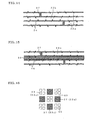
- FIG. 10 is a partial section view schematically showing one example of NOx purifying catalytic member used in an exhaust gas purifying system of the present invention.
- cells 23 are formed by arranging porous partition walls 24. Also by disposing a plugging portion 27 so as to plug the cell 23 at its end face, a plugged cell 33a is formed.
- the plugged cell 33a may be formed by arranging the plugging portion 27 so as to plug inside the cell 23 as shown in Fig. 11.
- a plurality of penetrating cells 33b are further formed that communicate between two end faces and are not formed with a plugging portion 27, by forming a partition wall 24, in the honeycomb catalyst carrier constituting the NOx purifying catalytic member. Forming such penetrating cells 33b is desirable because pressure loss is decreased.
- the proportion of number of penetrating cells 33b, to the total number of plugged cells 33a and the penetrating cells 33b is preferably 10% or more, more preferably 20 to 60%, and particularly preferably 40 to 50%. If the proportion of number of penetrating cells 33b, to the total number of plugged cells 33a and the penetrating cells 33b is less than 10%, pressure loss tends to increase.
- the penetrating cell 33b may be formed while the plugged cell 33a is formed by disposing a plugging portion 27 only on the side of end face of cell in which exhaust gas flows in.
- the penetrating cell 33b may be formed while the plugged cell 33a is formed by disposing a plugging portion 27 only on the side of end face of cell in which exhaust gas flows out.
- the plugging portions 27 may be disposed inside a cell while they are displaced from each other in the passage direction of the cell.
- a structure as shown in Figs. 15 and 16 in which a plugging portion 27 is disposed inside a cell to form a plugged cell 33a, and a penetrating cell 33c finely partitioned by a thin partition wall 45 is formed.
- the reference numeral 26 in Fig. 15 denotes a partition wall
- the reference numeral 40 in Fig. 16 denotes a thick partition wall.
- Preferred examples of materials forming the honeycomb filter and the honeycomb catalyst carrier include materials based on ceramics, sintered metal and the like.
- the honeycomb structure member 1 of the present embodiment is made of a material based on ceramics, as the ceramics, silicon carbide, cordierite, alumina titanate, Sialon, mullite, silicon nitride, zirconium phosphate, zirconia, titania, alumina or silica, or combination thereof can be recited as preferred examples.
- silicon carbide, cordierite, mullite, silicon nitride, alumina and the like ceramics are preferred from the view point of alkaline resistance.
- oxide ceramics are preferred in terms of cost.
- a shape of cross section cut diametrically in the surface perpendicular to communicating direction of cell is preferably the shape that is suited for the inner shape of exhaust system where it is to be mounted.
- Concrete shape examples include, circle, ellipse, prolate ellipsoid, trapezoid, triangle, quadrangle, hexagon, or left-right asymmetrical irregular shape. Among these, circle, ellipse and prolate ellipsoid are preferred.
- honeycomb filter and honeycomb catalyst carrier may be produced, for example, in accordance with a conventionally known production method of diesel particulate filter (DPF), by appropriately adjusting chemical composition of material, or by appropriately adjusting kind, particulate diameter, adding amount and the like of a pore forming agent which is used for forming porous structure.
- DPF diesel particulate filter
- the NOx purifying catalytic member may be produced by making the honeycomb catalyst carrier carry the NOx purifying catalyst in accordance with a production method which is a conventionally known method. To be more specific, first, a catalyst slurry containing NOx purifying catalyst is prepared. Then the porous surface of the partition wall of the honeycomb catalyst carrier is coated with this catalyst slurry by suction and the like method. Then it is dried at room temperature or under heating to give a NOx purifying catalytic member.
- NOx purifying efficiency Combustion gas composed of HC (propylene), CO, NO, H 2 O, O 2 and N 2 was caused to flow into an exhaust gas purifying system at a space velocity (sv) of 100000 h -1 , and at a temperature of 200°C. From NOx concentrations of combustion gas before and after flow-in, NOx purifying efficiency (%) was calculated.
- Pressure loss At room temperature, air was circulated at flow rate of 0.5 m 3 /min, and pressure loss at a NOx purifying catalytic member was measured. A relative value (pressure loss (relative value)), to pressure loss at a reference NOx purifying catalytic member was calculated.
- honeycomb catalyst carrier made of cordierite whose end is alternately plugged was prepared.
- This honeycomb catalyst carrier had outer diameter: 144mm, length: 152mm, cell density: 46. 5 cells/cm 2 , partition wall thickness: 0.305 mm, mean pore size of partition wall: 25 ⁇ m, and porosity: 65%.
- NOx purifying catalytic member (1) was prepared (structure: see Fig. 10).
- a honeycomb structure member made of cordierite whose end is alternately plugged was prepared.
- This honeycomb structure member had outer diameter: 144 mm, length: 152 mm, cell density: 46.5 cells/cm 2 , partition wall thickness: 0.305 mm, mean pore size of partition wall: 15 ⁇ m, and porosity: 60%.
- oxidation catalyst carrying Pt on grinded particles of gamma alumina and ceria in an amount of 100 g/L (Pt:2g/L) per volume of honeycomb structure member, DPF (2) was prepared.
- a honeycomb structure member made of cordierite having a penetrating cell was prepared.
- This honeycomb structure member had outer diameter: 144 mm, length: 80 mm, cell density: 46.5 cells/cm 2 , and partition wall thickness: 0.14 mm.
- partition wall surface of the honeycomb structure member with oxidation catalyst carrying Pt and Pd on grinded particles of gamma alumina and ceria so that Pt: 0.5 g/L and Pd: 3 g/L per volume of honeycomb structure member, DPF (3) was prepared.
- a honeycomb structure member made of cordierite having a penetrating cell was prepared.
- This honeycomb structure member had outer diameter: 144 mm, length: 80 mm, cell density: 62 cells/cm 2 , and partition wall thickness: 0.11 mm.
- partition wall surface of the honeycomb structure member with oxidation catalyst carrying Pt and Pd on grinded particles of gamma alumina and ceria so that Pt: 1 g/L and Pd: 2 g/L per volume of honeycomb structure member, DPF (4) was prepared.
- the prepared NOx purifying catalytic member (1), DPF(2), oxidation catalytic member (3), and oxidation catalytic member (4) were placed in the order of (3) - (2) - (4) - (1) , to create an exhaust gas flow path.
- an urea supply device for jetting and supplying the interior of the flow path with an urea aqueous solution.
- a NOx concentration sensor was provided, to produce an exhaust gas purifying system (Example 1) (layout: see Fig. 4) . Results of determined NOx purifying efficiency (%), and pressure loss (relative value) are shown in Table 1.
- Example 1 In an exhaust system of a diesel engine adapted to car of 2L displacement, the prepared NOx purifying catalytic member (1) and oxidation catalytic member (4) prepared in Example 1 were placed in the order of (4)-(1), to create an exhaust gas flow path. Just before the oxidation catalytic member (4), an urea supply device for jetting and supplying the interior of the flow path with an urea aqueous solution, and a NOx concentration sensor were provided, to produce an exhaust gas purifying system (Comparative example 1). Results of determined NOx purifying efficiency (%), and pressure loss (relative value) are shown in Table 1.
- Examples 2 to 17 An exhaust gas purifying system (Examples 2 to 17) was produced in a similar manner to Example 1 described above except that constructions of NOx purifying catalytic member and DPF, and layout of constituents are changed as shown in Table 1. Results of determined NOx purifying efficiency (%), and pressure loss (relative value) are shown in Table 1.
- NOx purifying catalytic member Mean pore size ( ⁇ m)
- DPF mean pore size/NOx purifying catalytic member mean pore size (%)
- Pressure loss (relative value) Cell density (cells/cm 2 ) Partition wall thickness (mm) Porosity (%) ⁇ *1 ( ⁇ m) Structure
- Example 1 46.5 0.305 65 0.4 Fig. 10 15 25 60 Fig. 4 85 100 Comparative example 1 46.5 0.305 65 0.4 Fig. 10 - 25 - *2 20 100
- Example 2 46.5 0.305 50 0.4 Fig. 10 15 25 60 Fig. 4 75 105
- Example 4 46.5 0.305 65 0.2 Fig. 10 15 25 60 Fig. 4 80 100 Example 5 46.5 0.305 65 0.4 Fig. 10 10 55 18.2 Fig. 4 72 95 Example 6 46.5 0.305 65 0.4 Fig. 10 15 62 24.2 Fig. 4 70 95 Example 7 46.5 0.305 65 0.4 Fig. 10 15 73 20.5 Fig. 4 58 95 Example 8 46.5 0.305 65 0.4 Fig. 10 25 85 29.4 Fig. 4 55 95 Example 9 96.5 0.305 65 0.4 Fig. 10 35 105 33.3 Fig. 4 50 95 Example 10 46.5 0.2 65 0.4 Fig. 10 15 25 60 Fig. 4 65 95 Example 11 46.5 0.4 65 0.4 Fig. 10 15 25 60 Fig. 4 80 100 Example 5 46.5 0.305 65 0.4 Fig. 10 10 55 18.2 Fig. 4 72 95 Example 6 46.5 0.305 65 0.4 Fig. 10 15 62 24.2 Fig. 4 70 95 Example 7 46.5 0.305 65 0.4 Fig. 10 15 73 20.5 Fig.
- Example 12 15 0.305 65 0.4 Fig. 10 15 25 60 Fig. 4 50 85 Example 13 92 0.305 65 0.4 Fig. 10 15 25 60 Fig. 4 70 120 Example 14 96.5 0.305 65 0.4 Fig. 13 *3 15 25 60 Fig. 4 50 70 Example 15 46.5 0.305 65 0.4 Fig. 13 *4 15 25 60 Fig. 4 55 40 Example 16 46.5 0.305 65 0.4 Fig. 13 *5 15 25 60 Fig. 4 54 30 Example 17 46.5 0.305 65 0.4 Fig. 10 15 25 60 Fig.
- the exhaust gas purifying systems of Examples 1 to 17 apparently show excellent NOx purifying efficiency compared to the exhaust gas purifying system of Comparative example 1. As for pressure loss, the exhaust gas purifying systems of Examples 1 to 17 showed acceptable ranges.
- a NOx purifying catalytic member which is identical to that used in Example 1 was prepared.
- porous surface and partition wall surface of the partition wall of the NOx purifying catalytic member with oxidation catalyst carrying Pt on gamma alumina and ceria in an amount of 100g/L (Pt : 2g/L) per volume of honeycomb structure member, a NOx purifying catalytic member (1') with oxidation catalyst was prepared.
- DPF (2') which is identical to Example 1 described above except for coating with oxidation catalyst was prepared.
- the prepared NOx purifying catalytic member (1'), DPF (2') and oxidation catalytic member (3) were placed in the order of (2')-(1')-(3) so that the length between an outlet end face of DPF (2') and an inlet end face of NOx purifying catalytic member (1') was 0.1 m, 0.4 m, 0.8 m, and 1.5 m, to create an exhaust gas flow path.
- an urea supply device for jetting and supplying the interior of the flow path with an urea aqueous solution was disposed.
- NOx purifying catalytic member Mean pore size ( ⁇ m) DPF mean pore size/NOx purifying catalytic member mean pore size (%) Layout Length between DPF outlet end face and NOx purifying catalytic member inlet end face NOx purifying efficiency (%) Pressure loss (relative value) Cell density (cells/c m 2 ) Partition wall thickne ss (mm) Porosity (%) ⁇ *1 ( ⁇ m) Structure DPF NOx purifying catalyst member Example 18 46.5 0.305 65 0.4 Fig. 10 15 25 60 Fig. 6 0.1 90 100 Example 19 46.5 0.305 65 0.4 Fig. 10 15 25 60 Fig. 6 0.4 88 100 Example 20 46.5 0.305 65 0.4 Fig. 10 15 25 60 Fig. 6 0.8 85 100 Example 21 46.5 0.305 65 0.4 Fig. 10 15 25 60 Fig. 6 1.5 65 100 *1: common logarithm standard deviation ⁇ of pore size distribution
- exhaust gas purifying systems of Examples 18 to 21 achieve low pressure loss and excellent NOx purifying efficiency. It was demonstrated that the longer the length between DPF outlet end face and NOx purifying catalytic member inlet end face, the lower the NOx purifying efficiency is.
- the exhaust gas purifying system of the present invention realizes excellent purifying efficiency of NOx and low pressure loss, and can be mounted in limited space. Therefore, the exhaust gas purifying system of the present invention is suited for use in purification of NOx contained in exhaust gas discharged from, for example, stationary engines for automobile, construction machinery, and industrial applications, and from burning appliances.
Applications Claiming Priority (2)
| Application Number | Priority Date | Filing Date | Title |
|---|---|---|---|
| JP2006084228 | 2006-03-24 | ||
| JP2007035417A JP2007285295A (ja) | 2006-03-24 | 2007-02-15 | 排気ガス浄化システム |
Publications (3)
| Publication Number | Publication Date |
|---|---|
| EP1837494A2 true EP1837494A2 (de) | 2007-09-26 |
| EP1837494A3 EP1837494A3 (de) | 2009-04-29 |
| EP1837494B1 EP1837494B1 (de) | 2012-05-02 |
Family
ID=38191124
Family Applications (1)
| Application Number | Title | Priority Date | Filing Date |
|---|---|---|---|
| EP07251151A Active EP1837494B1 (de) | 2006-03-24 | 2007-03-20 | Abgasreinigungssystem |
Country Status (3)
| Country | Link |
|---|---|
| US (1) | US7763222B2 (de) |
| EP (1) | EP1837494B1 (de) |
| JP (1) | JP2007285295A (de) |
Cited By (8)
| Publication number | Priority date | Publication date | Assignee | Title |
|---|---|---|---|---|
| WO2009067163A2 (en) * | 2007-11-20 | 2009-05-28 | Corning Incorporated | Washcoat loaded porous ceramics with low backpressure |
| WO2009089156A1 (en) * | 2008-01-07 | 2009-07-16 | Basf Catalysts Llc | Mitigation of particulates and nox in engine exhaust |
| WO2011128026A1 (de) * | 2010-04-14 | 2011-10-20 | Umicore Ag & Co. Kg | Reduktionskatalytisch beschichtetes dieselpartikelfilter mit verbesserten eigenschaften |
| EP2556876A1 (de) * | 2011-06-17 | 2013-02-13 | NGK Insulators, Ltd. | Abgasreinigungsfilter |
| RU2504668C2 (ru) * | 2008-07-09 | 2014-01-20 | Джонсон Мэттей Паблик Лимитед Компани | Выхлопная система для двигателя внутреннего сгорания, работающего на бедных смесях |
| US8945495B2 (en) * | 2008-10-21 | 2015-02-03 | GM Global Technology Operations LLC | Method and architecture for reducing NOX and particulate matter emissions in exhaust gas from hydrocarbon fuel source with a fuel lean combustion mixture |
| US9051857B2 (en) | 2008-11-04 | 2015-06-09 | Unicore Ag & Co. Kg | Diesel particle filter with improved back pressure characteristics |
| EP2567078B1 (de) | 2010-05-05 | 2017-09-27 | BASF Corporation | Katalytische russfilter sowie emissionsverarbeitungssysteme und -verfahren |
Families Citing this family (47)
| Publication number | Priority date | Publication date | Assignee | Title |
|---|---|---|---|---|
| US20060078479A1 (en) * | 2004-10-07 | 2006-04-13 | Caterpillar Inc. | Filter assembly for an exhaust treatment device |
| TWI449572B (zh) * | 2006-11-29 | 2014-08-21 | Umicore Shokubai Japan Co Ltd | Oxidation catalyst and the oxidation catalyst using an exhaust gas purification system |
| JP4985351B2 (ja) * | 2007-11-28 | 2012-07-25 | 三菱重工業株式会社 | 排ガス処理触媒および排ガス浄化装置 |
| JP5408865B2 (ja) * | 2007-11-30 | 2014-02-05 | 日本碍子株式会社 | ハニカム触媒体 |
| JP5101324B2 (ja) * | 2008-02-07 | 2012-12-19 | 日立建機株式会社 | 建設機械のNOx低減装置の配設構造 |
| KR100969378B1 (ko) | 2008-03-31 | 2010-07-09 | 현대자동차주식회사 | 배기 가스 정화 장치 |
| DE102008019814A1 (de) * | 2008-04-19 | 2009-10-22 | Daimler Ag | Abgasreinigungskörper und Brennkraftmaschine mit Abgasreinigungskörper |
| JP2010013969A (ja) * | 2008-07-02 | 2010-01-21 | Sumitomo Electric Ind Ltd | 排気ガス浄化装置 |
| DE102008035562A1 (de) * | 2008-07-30 | 2010-02-04 | Emitec Gesellschaft Für Emissionstechnologie Mbh | Abgasreinigungssystem für Dieselmotoren von Nutzkraftfahrzeugen |
| US20100050604A1 (en) * | 2008-08-28 | 2010-03-04 | John William Hoard | SCR-LNT CATALYST COMBINATION FOR IMPROVED NOx CONTROL OF LEAN GASOLINE AND DIESEL ENGINES |
| DE102008055890A1 (de) * | 2008-11-05 | 2010-05-12 | Süd-Chemie AG | Partikelminderung mit kombiniertem SCR- und NH3-Schlupf-Katalysator |
| US8844274B2 (en) * | 2009-01-09 | 2014-09-30 | Ford Global Technologies, Llc | Compact diesel engine exhaust treatment system |
| JP2010227767A (ja) * | 2009-03-26 | 2010-10-14 | Ngk Insulators Ltd | ハニカムフィルタ |
| US9662611B2 (en) | 2009-04-03 | 2017-05-30 | Basf Corporation | Emissions treatment system with ammonia-generating and SCR catalysts |
| US8062618B2 (en) * | 2009-04-17 | 2011-11-22 | Ford Global Technologies, Llc | Exhaust aftertreatment system and method of treating exhaust gas |
| EP2435673B1 (de) * | 2009-05-29 | 2022-08-03 | Corning Inc. | Partikelfilter mit einer mit wenig russ beladenen beschichtung |
| US8207084B2 (en) * | 2009-06-23 | 2012-06-26 | Ford Global Technologies, Llc | Urea-resistant catalytic units and methods of using the same |
| US8545796B2 (en) * | 2009-07-31 | 2013-10-01 | Cristal Usa Inc. | Silica-stabilized ultrafine anatase titania, vanadia catalysts, and methods of production thereof |
| WO2011042991A1 (ja) | 2009-10-09 | 2011-04-14 | イビデン株式会社 | ハニカムフィルタ |
| WO2011042992A1 (ja) * | 2009-10-09 | 2011-04-14 | イビデン株式会社 | ハニカムフィルタ |
| JP4920752B2 (ja) * | 2010-01-05 | 2012-04-18 | 日本碍子株式会社 | ハニカム構造体 |
| GB201003781D0 (en) | 2010-03-08 | 2010-04-21 | Johnson Matthey Plc | Improvements in the control of vehicle emissions |
| JP2011194342A (ja) * | 2010-03-19 | 2011-10-06 | Ngk Insulators Ltd | ハニカム構造体およびハニカム触媒体 |
| JP5649836B2 (ja) * | 2010-03-23 | 2015-01-07 | 日本碍子株式会社 | ハニカム触媒体 |
| US8071038B2 (en) * | 2010-06-09 | 2011-12-06 | Ford Global Technologies, Llc | Progressive catalyst loading for integrated particulate filter and selective catalytic reduction unit |
| WO2012008962A1 (en) * | 2010-07-15 | 2012-01-19 | International Engine Intellectual Property Company, Llc | Anti-clogging method for exhaust gas treatment |
| US9441517B2 (en) * | 2010-09-02 | 2016-09-13 | Ford Global Technologies, Llc | Diesel engine exhaust treatment system |
| US8137648B2 (en) * | 2010-10-12 | 2012-03-20 | Ford Global Technologies, Llc | Diesel engine exhaust treatment system and method including a platinum group metal trapping device |
| US8062601B2 (en) * | 2010-10-26 | 2011-11-22 | Ford Global Technologies, Llc | Emission SCR NOX aftertreatment system having reduced SO3 generation and improved durability |
| US8668877B2 (en) | 2010-11-24 | 2014-03-11 | Basf Corporation | Diesel oxidation catalyst articles and methods of making and using |
| US8609032B2 (en) | 2010-11-29 | 2013-12-17 | Corning Incorporated | Porous ceramic honeycomb articles and methods for making the same |
| KR101440009B1 (ko) | 2011-07-04 | 2014-09-12 | 도요타 지도샤(주) | 내연 기관의 배기 정화 장치 |
| RU2637510C2 (ru) * | 2011-08-03 | 2017-12-05 | Джонсон Мэтти Плс | Экструдированный катализатор с сотовой структурой |
| US9057324B2 (en) | 2012-12-12 | 2015-06-16 | Caterpillar Inc. | Six-stroke engine system with blowdown turbocharger |
| US9151222B2 (en) | 2012-12-12 | 2015-10-06 | Caterpillar Inc. | Six-stroke combustion cycle engine and process |
| US8978601B2 (en) | 2012-12-12 | 2015-03-17 | Caterpillar Inc. | Six-stroke engine system with blowdown exhaust system |
| US9133764B2 (en) | 2012-12-12 | 2015-09-15 | Caterpillar Inc. | Six-stroke engine system with blowdown exhaust recirculation |
| US8978602B2 (en) | 2012-12-12 | 2015-03-17 | Caterpillar Inc. | Six-stroke engine power density matching system and method |
| US9181830B2 (en) | 2012-12-12 | 2015-11-10 | Caterpillar Inc. | After-treatment system and method for six-stroke combustion cycle |
| US8978603B2 (en) | 2012-12-12 | 2015-03-17 | Caterpillar Inc. | Six-stroke internal combustion engine valve activation system and method for operating such engine |
| DE102014207530A1 (de) | 2014-04-22 | 2015-10-22 | Bayerische Motoren Werke Aktiengesellschaft | Katalysatorbaugruppe, die Baugruppe enthaltende Vorrichtung zur Reinigung von Abgasen eines Verbrennungsmotors, Baukastensystem für die Baugruppe, und Verfahren zur Herstellung der Baugruppe |
| JP2016217305A (ja) | 2015-05-25 | 2016-12-22 | 本田技研工業株式会社 | 内燃機関の排気浄化装置 |
| JP6709652B2 (ja) * | 2016-03-24 | 2020-06-17 | 日本碍子株式会社 | 多孔質セラミックス構造体 |
| CN106762041A (zh) * | 2016-12-28 | 2017-05-31 | 中船动力研究院有限公司 | 具有NOx捕集功能的船舶柴油机催化还原装置 |
| JP6605522B2 (ja) | 2017-03-09 | 2019-11-13 | 株式会社キャタラー | 排ガス浄化用触媒 |
| JP7449720B2 (ja) * | 2020-03-02 | 2024-03-14 | 日本碍子株式会社 | ハニカムフィルタ |
| CN114618255B (zh) * | 2021-06-18 | 2023-06-02 | 重庆亿森动力环境科技有限公司 | 一种混合气体自动过滤装置 |
Citations (3)
| Publication number | Priority date | Publication date | Assignee | Title |
|---|---|---|---|---|
| JP2003033664A (ja) * | 2001-07-25 | 2003-02-04 | Ngk Insulators Ltd | 排ガス浄化用ハニカム構造体及び排ガス浄化用ハニカム触媒体 |
| WO2004022935A1 (en) * | 2002-09-05 | 2004-03-18 | Johnson Matthey Public Limited Company | Exhaust system for lean burn ic engines |
| WO2004061278A1 (de) * | 2003-01-02 | 2004-07-22 | Daimlerchrysler Ag | Abgasnachbehandlungseinrichtung und -verfahren |
Family Cites Families (12)
| Publication number | Priority date | Publication date | Assignee | Title |
|---|---|---|---|---|
| US4329162A (en) * | 1980-07-03 | 1982-05-11 | Corning Glass Works | Diesel particulate trap |
| JPS603420A (ja) * | 1983-06-21 | 1985-01-09 | Nissan Motor Co Ltd | 内燃機関のパ−テイキユレ−ト・トラツプ |
| JP2001329829A (ja) * | 2000-05-19 | 2001-11-30 | Denso Corp | ディーゼルパティキュレートフィルタ |
| JP2002089246A (ja) * | 2000-09-20 | 2002-03-27 | Hitachi Ltd | 内燃機関の排ガス浄化方法および排ガス浄化装置 |
| JP2002336656A (ja) | 2001-05-21 | 2002-11-26 | Toyota Motor Corp | ディーゼル排ガス浄化用触媒 |
| JP2004138022A (ja) * | 2002-10-21 | 2004-05-13 | Babcock Hitachi Kk | ディーゼル排ガスの処理方法および装置 |
| JP4320702B2 (ja) * | 2002-11-11 | 2009-08-26 | 日立金属株式会社 | 排気ガス浄化装置 |
| JP4316901B2 (ja) * | 2003-03-07 | 2009-08-19 | バブコック日立株式会社 | ディーゼル排ガス処理方法および処理装置 |
| US7229597B2 (en) * | 2003-08-05 | 2007-06-12 | Basfd Catalysts Llc | Catalyzed SCR filter and emission treatment system |
| JP2005052750A (ja) * | 2003-08-05 | 2005-03-03 | Hitachi Metals Ltd | 排気ガス浄化装置用セラミックハニカム触媒及び排気ガス浄化装置 |
| US7490464B2 (en) * | 2003-11-04 | 2009-02-17 | Basf Catalysts Llc | Emissions treatment system with NSR and SCR catalysts |
| JP4762560B2 (ja) * | 2005-01-28 | 2011-08-31 | バブコック日立株式会社 | 排ガス中粒状物質除去用フィルタおよび排ガス浄化方法 |
-
2007
- 2007-02-15 JP JP2007035417A patent/JP2007285295A/ja active Pending
- 2007-03-20 US US11/725,442 patent/US7763222B2/en active Active
- 2007-03-20 EP EP07251151A patent/EP1837494B1/de active Active
Patent Citations (3)
| Publication number | Priority date | Publication date | Assignee | Title |
|---|---|---|---|---|
| JP2003033664A (ja) * | 2001-07-25 | 2003-02-04 | Ngk Insulators Ltd | 排ガス浄化用ハニカム構造体及び排ガス浄化用ハニカム触媒体 |
| WO2004022935A1 (en) * | 2002-09-05 | 2004-03-18 | Johnson Matthey Public Limited Company | Exhaust system for lean burn ic engines |
| WO2004061278A1 (de) * | 2003-01-02 | 2004-07-22 | Daimlerchrysler Ag | Abgasnachbehandlungseinrichtung und -verfahren |
Non-Patent Citations (2)
| Title |
|---|
| BUNTING A: "SPRINGING THE TRAP" AUTOMOTIVE ENGINEER, PROFESSIONAL ENGINEERING PUBLISHING, LONDON, GB, vol. 25, no. 5, 1 May 2000 (2000-05-01), page 73/74, XP000936087 ISSN: 0307-6490 * |
| CHANDLER GUY R ET AL: "An integrated SCR and Continuously Regenerating Trap System to meet Future NOx and PM Legislation" SAE TECHNICAL PAPER SERIES, SOCIETY OF AUTOMOTIVE ENGINEERS, WARRENDALE, PA, US, vol. 2000-01-0188, 6 March 2000 (2000-03-06), pages 1-6, XP009109506 ISSN: 0148-7191 * |
Cited By (12)
| Publication number | Priority date | Publication date | Assignee | Title |
|---|---|---|---|---|
| WO2009067163A2 (en) * | 2007-11-20 | 2009-05-28 | Corning Incorporated | Washcoat loaded porous ceramics with low backpressure |
| WO2009067163A3 (en) * | 2007-11-20 | 2010-03-18 | Corning Incorporated | Washcoat loaded porous ceramics with low backpressure |
| US7842371B2 (en) | 2007-11-20 | 2010-11-30 | Corning Incorporated | Washcoat loaded porous ceramics with low backpressure |
| WO2009089156A1 (en) * | 2008-01-07 | 2009-07-16 | Basf Catalysts Llc | Mitigation of particulates and nox in engine exhaust |
| RU2504668C2 (ru) * | 2008-07-09 | 2014-01-20 | Джонсон Мэттей Паблик Лимитед Компани | Выхлопная система для двигателя внутреннего сгорания, работающего на бедных смесях |
| US8945495B2 (en) * | 2008-10-21 | 2015-02-03 | GM Global Technology Operations LLC | Method and architecture for reducing NOX and particulate matter emissions in exhaust gas from hydrocarbon fuel source with a fuel lean combustion mixture |
| US9051857B2 (en) | 2008-11-04 | 2015-06-09 | Unicore Ag & Co. Kg | Diesel particle filter with improved back pressure characteristics |
| WO2011128026A1 (de) * | 2010-04-14 | 2011-10-20 | Umicore Ag & Co. Kg | Reduktionskatalytisch beschichtetes dieselpartikelfilter mit verbesserten eigenschaften |
| US9347354B2 (en) | 2010-04-14 | 2016-05-24 | Umicore Ag & Co. Kg | Reduction-catalyst-coated diesel particle filter having improved characteristics |
| EP2567078B1 (de) | 2010-05-05 | 2017-09-27 | BASF Corporation | Katalytische russfilter sowie emissionsverarbeitungssysteme und -verfahren |
| EP2556876A1 (de) * | 2011-06-17 | 2013-02-13 | NGK Insulators, Ltd. | Abgasreinigungsfilter |
| US8734558B2 (en) | 2011-06-17 | 2014-05-27 | Ngk Insulators, Ltd. | Exhaust gas purification filter |
Also Published As
| Publication number | Publication date |
|---|---|
| US7763222B2 (en) | 2010-07-27 |
| EP1837494A3 (de) | 2009-04-29 |
| JP2007285295A (ja) | 2007-11-01 |
| US20070224093A1 (en) | 2007-09-27 |
| EP1837494B1 (de) | 2012-05-02 |
Similar Documents
| Publication | Publication Date | Title |
|---|---|---|
| EP1837494B1 (de) | Abgasreinigungssystem | |
| EP3207990B1 (de) | Abgasreinigungskatalysator | |
| JP6023395B2 (ja) | 触媒担持フィルタ | |
| KR101765354B1 (ko) | 존형 촉매화 매연 필터 | |
| EP1657410B1 (de) | Filterkatalysator | |
| EP1839748B1 (de) | Wabenförmiger katalytischer Körper | |
| JP5726414B2 (ja) | 触媒担持フィルタ、及び排ガス浄化システム | |
| EP3254759B1 (de) | Abgasreinigungskatalysator | |
| EP2382031B1 (de) | Abgasbehandlungssysteme und -verfahren mit einem katalysierten scr-filter und stromabwärtigem scr-katalysator | |
| EP2276555B1 (de) | Abgasreinigungskatalysator und verfahren zu seiner herstellung | |
| EP3689457B1 (de) | Abgasreinigungskatalysator | |
| EP2070579B1 (de) | Wabenstruktur, wabenförmiger katalytischer Körper und Verfahren zur Herstellung dieses Körpers | |
| EP1446215B1 (de) | Dieselteilchenfilter mit kontinuierlicher regeneration | |
| EP1920840A1 (de) | Wabenstruktur und wabenförmige katalytische struktur | |
| EP1847320A1 (de) | Katalysatorkörper und Herstellungsverfahren dafür | |
| EP1935489A1 (de) | Wabenförmiger katalytischer körper und zugehöriges herstellungsverfahren | |
| JPWO2007094379A1 (ja) | ハニカム構造体及びハニカム触媒体 | |
| EP2103342A1 (de) | Katalysator beschichteter Filter | |
| US20070189936A1 (en) | Exhaust gas-cleaning apparatus | |
| EP1710009A1 (de) | Dieselabgaskatalysator | |
| EP1961482A1 (de) | Katalysatorträger | |
| EP3636340B1 (de) | Katalysator zur abgasreinigung | |
| EP2505252B1 (de) | Wabenstruktur und wabenförmiger katalytischer Körper | |
| JP6605522B2 (ja) | 排ガス浄化用触媒 | |
| JP4320702B2 (ja) | 排気ガス浄化装置 |
Legal Events
| Date | Code | Title | Description |
|---|---|---|---|
| PUAI | Public reference made under article 153(3) epc to a published international application that has entered the european phase |
Free format text: ORIGINAL CODE: 0009012 |
|
| AK | Designated contracting states |
Kind code of ref document: A2 Designated state(s): AT BE BG CH CY CZ DE DK EE ES FI FR GB GR HU IE IS IT LI LT LU LV MC MT NL PL PT RO SE SI SK TR |
|
| AX | Request for extension of the european patent |
Extension state: AL BA HR MK YU |
|
| PUAL | Search report despatched |
Free format text: ORIGINAL CODE: 0009013 |
|
| AK | Designated contracting states |
Kind code of ref document: A3 Designated state(s): AT BE BG CH CY CZ DE DK EE ES FI FR GB GR HU IE IS IT LI LT LU LV MC MT NL PL PT RO SE SI SK TR |
|
| AX | Request for extension of the european patent |
Extension state: AL BA HR MK RS |
|
| 17P | Request for examination filed |
Effective date: 20091023 |
|
| AKX | Designation fees paid |
Designated state(s): DE FR |
|
| 17Q | First examination report despatched |
Effective date: 20100624 |
|
| GRAP | Despatch of communication of intention to grant a patent |
Free format text: ORIGINAL CODE: EPIDOSNIGR1 |
|
| GRAS | Grant fee paid |
Free format text: ORIGINAL CODE: EPIDOSNIGR3 |
|
| GRAA | (expected) grant |
Free format text: ORIGINAL CODE: 0009210 |
|
| AK | Designated contracting states |
Kind code of ref document: B1 Designated state(s): DE FR |
|
| REG | Reference to a national code |
Ref country code: DE Ref legal event code: R096 Ref document number: 602007022388 Country of ref document: DE Effective date: 20120705 |
|
| PLBE | No opposition filed within time limit |
Free format text: ORIGINAL CODE: 0009261 |
|
| STAA | Information on the status of an ep patent application or granted ep patent |
Free format text: STATUS: NO OPPOSITION FILED WITHIN TIME LIMIT |
|
| 26N | No opposition filed |
Effective date: 20130205 |
|
| REG | Reference to a national code |
Ref country code: DE Ref legal event code: R097 Ref document number: 602007022388 Country of ref document: DE Effective date: 20130205 |
|
| REG | Reference to a national code |
Ref country code: FR Ref legal event code: ST Effective date: 20131129 |
|
| PG25 | Lapsed in a contracting state [announced via postgrant information from national office to epo] |
Ref country code: FR Free format text: LAPSE BECAUSE OF NON-PAYMENT OF DUE FEES Effective date: 20130402 |
|
| PGFP | Annual fee paid to national office [announced via postgrant information from national office to epo] |
Ref country code: DE Payment date: 20230131 Year of fee payment: 17 |