EP1837410B1 - Verfahren und Vorrichtung zum schnellen Abkühlen von Werkstücken - Google Patents
Verfahren und Vorrichtung zum schnellen Abkühlen von Werkstücken Download PDFInfo
- Publication number
- EP1837410B1 EP1837410B1 EP06015701A EP06015701A EP1837410B1 EP 1837410 B1 EP1837410 B1 EP 1837410B1 EP 06015701 A EP06015701 A EP 06015701A EP 06015701 A EP06015701 A EP 06015701A EP 1837410 B1 EP1837410 B1 EP 1837410B1
- Authority
- EP
- European Patent Office
- Prior art keywords
- cooling
- cold box
- liquid gas
- workpiece
- liquid
- Prior art date
- Legal status (The legal status is an assumption and is not a legal conclusion. Google has not performed a legal analysis and makes no representation as to the accuracy of the status listed.)
- Not-in-force
Links
- 238000001816 cooling Methods 0.000 title claims abstract description 72
- 238000000034 method Methods 0.000 title claims abstract description 24
- 238000009434 installation Methods 0.000 title claims 2
- 239000007789 gas Substances 0.000 claims abstract description 73
- 239000007788 liquid Substances 0.000 claims abstract description 70
- 239000002826 coolant Substances 0.000 claims abstract description 30
- 239000000203 mixture Substances 0.000 claims abstract description 29
- 230000008016 vaporization Effects 0.000 claims abstract description 7
- XKRFYHLGVUSROY-UHFFFAOYSA-N Argon Chemical compound [Ar] XKRFYHLGVUSROY-UHFFFAOYSA-N 0.000 claims abstract description 6
- CURLTUGMZLYLDI-UHFFFAOYSA-N Carbon dioxide Chemical compound O=C=O CURLTUGMZLYLDI-UHFFFAOYSA-N 0.000 claims abstract description 6
- VNWKTOKETHGBQD-UHFFFAOYSA-N methane Chemical compound C VNWKTOKETHGBQD-UHFFFAOYSA-N 0.000 claims abstract description 6
- 239000001307 helium Substances 0.000 claims abstract description 4
- 229910052734 helium Inorganic materials 0.000 claims abstract description 4
- SWQJXJOGLNCZEY-UHFFFAOYSA-N helium atom Chemical compound [He] SWQJXJOGLNCZEY-UHFFFAOYSA-N 0.000 claims abstract description 4
- 229910052786 argon Inorganic materials 0.000 claims abstract description 3
- 229910002092 carbon dioxide Inorganic materials 0.000 claims abstract description 3
- 239000001569 carbon dioxide Substances 0.000 claims abstract description 3
- IJGRMHOSHXDMSA-UHFFFAOYSA-N Atomic nitrogen Chemical compound N#N IJGRMHOSHXDMSA-UHFFFAOYSA-N 0.000 claims description 12
- 238000001704 evaporation Methods 0.000 claims description 8
- 230000008020 evaporation Effects 0.000 claims description 7
- 229910052757 nitrogen Inorganic materials 0.000 claims description 6
- 239000001257 hydrogen Substances 0.000 claims description 3
- 229910052739 hydrogen Inorganic materials 0.000 claims description 3
- 125000004435 hydrogen atom Chemical class [H]* 0.000 claims 1
- 238000009834 vaporization Methods 0.000 abstract description 6
- -1 hydrogen- Chemical class 0.000 abstract description 2
- QJGQUHMNIGDVPM-UHFFFAOYSA-N nitrogen(.) Chemical compound [N] QJGQUHMNIGDVPM-UHFFFAOYSA-N 0.000 abstract 1
- 230000005855 radiation Effects 0.000 description 7
- 238000010791 quenching Methods 0.000 description 5
- 230000000171 quenching effect Effects 0.000 description 5
- 230000007246 mechanism Effects 0.000 description 3
- RYGMFSIKBFXOCR-UHFFFAOYSA-N Copper Chemical compound [Cu] RYGMFSIKBFXOCR-UHFFFAOYSA-N 0.000 description 2
- 229910000831 Steel Inorganic materials 0.000 description 2
- 229910052802 copper Inorganic materials 0.000 description 2
- 239000010949 copper Substances 0.000 description 2
- 239000002184 metal Substances 0.000 description 2
- 229910052751 metal Inorganic materials 0.000 description 2
- 239000011265 semifinished product Substances 0.000 description 2
- 239000010959 steel Substances 0.000 description 2
- UFHFLCQGNIYNRP-UHFFFAOYSA-N Hydrogen Chemical compound [H][H] UFHFLCQGNIYNRP-UHFFFAOYSA-N 0.000 description 1
- 238000004140 cleaning Methods 0.000 description 1
- 238000005260 corrosion Methods 0.000 description 1
- 230000007797 corrosion Effects 0.000 description 1
- 230000000694 effects Effects 0.000 description 1
- 239000000839 emulsion Substances 0.000 description 1
- 238000010438 heat treatment Methods 0.000 description 1
- 150000002431 hydrogen Chemical class 0.000 description 1
- 238000004519 manufacturing process Methods 0.000 description 1
- 239000003921 oil Substances 0.000 description 1
- 150000003839 salts Chemical class 0.000 description 1
- XLYOFNOQVPJJNP-UHFFFAOYSA-N water Substances O XLYOFNOQVPJJNP-UHFFFAOYSA-N 0.000 description 1
Images


Classifications
-
- F—MECHANICAL ENGINEERING; LIGHTING; HEATING; WEAPONS; BLASTING
- F25—REFRIGERATION OR COOLING; COMBINED HEATING AND REFRIGERATION SYSTEMS; HEAT PUMP SYSTEMS; MANUFACTURE OR STORAGE OF ICE; LIQUEFACTION SOLIDIFICATION OF GASES
- F25D—REFRIGERATORS; COLD ROOMS; ICE-BOXES; COOLING OR FREEZING APPARATUS NOT OTHERWISE PROVIDED FOR
- F25D3/00—Devices using other cold materials; Devices using cold-storage bodies
- F25D3/10—Devices using other cold materials; Devices using cold-storage bodies using liquefied gases, e.g. liquid air
-
- C—CHEMISTRY; METALLURGY
- C21—METALLURGY OF IRON
- C21D—MODIFYING THE PHYSICAL STRUCTURE OF FERROUS METALS; GENERAL DEVICES FOR HEAT TREATMENT OF FERROUS OR NON-FERROUS METALS OR ALLOYS; MAKING METAL MALLEABLE, e.g. BY DECARBURISATION OR TEMPERING
- C21D1/00—General methods or devices for heat treatment, e.g. annealing, hardening, quenching or tempering
- C21D1/56—General methods or devices for heat treatment, e.g. annealing, hardening, quenching or tempering characterised by the quenching agents
- C21D1/613—Gases; Liquefied or solidified normally gaseous material
-
- C—CHEMISTRY; METALLURGY
- C21—METALLURGY OF IRON
- C21D—MODIFYING THE PHYSICAL STRUCTURE OF FERROUS METALS; GENERAL DEVICES FOR HEAT TREATMENT OF FERROUS OR NON-FERROUS METALS OR ALLOYS; MAKING METAL MALLEABLE, e.g. BY DECARBURISATION OR TEMPERING
- C21D1/00—General methods or devices for heat treatment, e.g. annealing, hardening, quenching or tempering
- C21D1/62—Quenching devices
- C21D1/667—Quenching devices for spray quenching
-
- C—CHEMISTRY; METALLURGY
- C21—METALLURGY OF IRON
- C21D—MODIFYING THE PHYSICAL STRUCTURE OF FERROUS METALS; GENERAL DEVICES FOR HEAT TREATMENT OF FERROUS OR NON-FERROUS METALS OR ALLOYS; MAKING METAL MALLEABLE, e.g. BY DECARBURISATION OR TEMPERING
- C21D9/00—Heat treatment, e.g. annealing, hardening, quenching or tempering, adapted for particular articles; Furnaces therefor
- C21D9/08—Heat treatment, e.g. annealing, hardening, quenching or tempering, adapted for particular articles; Furnaces therefor for tubular bodies or pipes
-
- C—CHEMISTRY; METALLURGY
- C21—METALLURGY OF IRON
- C21D—MODIFYING THE PHYSICAL STRUCTURE OF FERROUS METALS; GENERAL DEVICES FOR HEAT TREATMENT OF FERROUS OR NON-FERROUS METALS OR ALLOYS; MAKING METAL MALLEABLE, e.g. BY DECARBURISATION OR TEMPERING
- C21D9/00—Heat treatment, e.g. annealing, hardening, quenching or tempering, adapted for particular articles; Furnaces therefor
- C21D9/08—Heat treatment, e.g. annealing, hardening, quenching or tempering, adapted for particular articles; Furnaces therefor for tubular bodies or pipes
- C21D9/085—Cooling or quenching
-
- F—MECHANICAL ENGINEERING; LIGHTING; HEATING; WEAPONS; BLASTING
- F25—REFRIGERATION OR COOLING; COMBINED HEATING AND REFRIGERATION SYSTEMS; HEAT PUMP SYSTEMS; MANUFACTURE OR STORAGE OF ICE; LIQUEFACTION SOLIDIFICATION OF GASES
- F25D—REFRIGERATORS; COLD ROOMS; ICE-BOXES; COOLING OR FREEZING APPARATUS NOT OTHERWISE PROVIDED FOR
- F25D3/00—Devices using other cold materials; Devices using cold-storage bodies
- F25D3/12—Devices using other cold materials; Devices using cold-storage bodies using solidified gases, e.g. carbon-dioxide snow
Definitions
- the invention relates to a method for cooling a workpiece, wherein the workpiece is introduced into a cooling zone adjacent to a cold box, and wherein a cooling medium is supplied to the cold box, wherein the cooling medium comprises a liquid gas or a liquid mixture whose heat of evaporation for cooling the Cold box and used for cooling the workpiece surface.
- the invention relates to a device for cooling a workpiece with a cold box with a feed for a cooling medium and with a cooling zone for receiving the workpiece, wherein the cold box and the cooling zone adjoin each other, and wherein the supply for the introduction of liquid gas or a liquid gas mixture is formed suitable.
- a variety of methods and devices for cooling are known.
- a variety of methods and devices for cooling and quenching workpieces have been used for centuries.
- Common is e.g. quenching in liquids such as oils, water, emulsions or others, quenching in salts or with the aid of gases.
- Gases are conventionally used in a variety of forms such as e.g. under high pressure, which increases the ability of the gas to transport thermal energy.
- prior art gases are brought into contact with the hot surface of a workpiece to be cooled at a high relative speed.
- the so-called "gas quenching” gas is brought into contact with the hot surface of the workpiece to be cooled under high pressure and at high outflow velocity.
- the document GB 1 287 325 A discloses apparatus for sequentially cooling workpieces that are transported through a thermally insulated chamber and cooled by evaporation of liquid nitrogen supplied to the chamber.
- the document US 5,083,436 discloses a device for cooling and shrinking workpieces that are transported to a processing station on a production line, comprising a cooling chamber, a transport device, at least one substantially vertical conduit for transporting a cryogenic liquid from a bath to an outlet above the bath and shafts for storing the cryogenic liquid bath, baffles for slowing down the countercurrent of cryogenic gas and a flap which holds the gas in the cooling chamber.
- a cooling method for pipes and other semi-finished products eg rods, profiles, wire, etc.
- the workpieces to be cooled as a bundle or individually, via a shape-matched nozzle array, on the gas
- the workpieces are blown, cooled while the workpieces are moved through the nozzle field.
- the nozzle field can also be housed in a shape-adapted manner.
- the cooling result could be even better, especially for workpieces with a high outlet temperature of over 550 ° C.
- the object of the present invention is to provide an improved method and a device for carrying out this method for cooling workpieces.
- the object is procedurally achieved in that the workpiece is introduced into a cooling zone adjacent to a cold box, and wherein a cooling medium of the cold box is supplied, wherein the cooling medium comprises a liquid gas or a liquid gas mixture whose heat of evaporation for cooling the cold box and is used for cooling the workpiece surface, and wherein the cooling medium via one or more nozzle (s) emerges from the cold box and is passed via the nozzle (s) in the cooling zone.
- the gas introduced into the cooling zone via the nozzles - in the liquid or gaseous state - is used to cool the workpiece by convection.
- the cooling medium also cools the cold box adjacent to the cooling zone. In this way, the dominating in particular at high temperatures heat transfer is amplified by radiation.
- the cooling medium used is preferably a liquid gas or a mixture of gases in liquid and gaseous form, the heat of vaporization of which is used for cooling the cold box and / or for cooling the workpiece surface.
- the environment of the workpiece is brought to a temperature which allows a particularly effective cooling of the workpiece.
- the method according to the invention can take into account the prevalence of heat emission by thermal radiation, which is present in this temperature range compared to the heat transfer via heat transfer or convection.
- liquid gas or a mixture of gases in liquid and gaseous form in addition to the particularly advantageous low temperature achieved with it, has the advantages of a clean, environmentally friendly process in which post-cleaning of the workpiece can be dispensed with Process-related corrosion occurs and the process flow is well controllable due to the good metering of the cooling medium. Overall, a highly effective cooling method is available in a device with only little spatial expansion.
- the liquid gas or the liquid gas mixture is completely or partially evaporated in the cold box, wherein the heat of vaporization is used wholly or partly for cooling the cold box.
- liquid gas or a mixture of gases in liquid and gaseous form is advantageously wholly or partially directly on the workpiece surface by evaporation, wherein the heat of vaporization is used wholly or partly for cooling the workpiece surface.
- the workpiece is moved through the cooling zone, wherein the cooling zone is adapted to the shape of the workpiece, so that the cooling medium on the one hand sufficiently long remains in the cooling zone, so that the workpiece surface can release sufficient heat to the cooling medium and the other now heated cooling medium with high speed leaves the cooling zone.
- the liquid gas or a mixture of gases in liquid and gaseous form is preferably introduced into the cooling zone at a high flow rate.
- liquid nitrogen, liquid hydrogen, liquid helium or liquid argon is used as the liquid gas mixture.
- liquid nitrogen, liquid hydrogen, liquid helium or liquid argon is used as the liquid gas mixture.
- liquid gas or the liquid gas mixture carbon dioxide and / or methane are mixed.
- the object is achieved by a device for cooling a workpiece with a cold box with a feed for a cooling medium and with a cooling zone for receiving the workpiece, the cold box and the cooling zone adjacent to each other, and wherein the supply for the introduction of liquid gas or a liquid gas mixture is suitably formed, and which is characterized in that one or more nozzles are attached to the cold box, that the cooling medium via the nozzle (s) exits the cold box and passed through the nozzle (s) in the cooling zone becomes.
- This design allows the cooling medium to rapidly heat exchange with the workpiece and absorbs the thermal radiation emanating from the workpiece from the cold box, the cold box having approximately the temperature of the liquid gas or liquefied gas mixture.
- the cold box is preferably provided as a device for evaporating the liquid gas or the liquid gas mixture.
- the cold box is adapted to the shape of the workpiece, so that only a very small distance between the nozzles for the cooling medium and the workpiece surface is provided.
- the cold box and the cooling zone are advantageously adjacent to one another, so that on the one hand the cooling medium emerging via the nozzles from the cold box rapidly exchanges heat with the workpiece and, on the other hand, the heat radiation emanating from the workpiece from the cold box is recorded.
- the cold box is for this purpose preferably designed so that it surrounds the workpiece on several sides.
- the cold box is divided into two or more cold box sections, which are each spaced from each other by a gap in the nozzle area.
- the invention provides a highly effective cooling or quenching process, especially for hot metal parts.
- the heat transfer takes place mainly by heat radiation.
- the cold box is kept low temperature by the supplied LPG.
- the cooling zone for receiving the workpiece.
- the temperature difference between the workpiece surface and the cold box is maximized by the cooling of the cold box, so that an optimal cooling by radiation takes place.
- the cooling medium is guided through nozzle openings in the cold box on the workpiece surface. This flow causes additional cooling by convection. Overall, the invention thus provides a particularly efficient utilization of the various heat transfer mechanisms.
- the FIG. 1 shows a workpiece 1, here a tube 1, which is moved along the direction indicated by the arrow 2 through the cold box 3, from which the tube 1 is wrapped.
- the cold box 3 is adapted to the shape of the tube 1.
- Liquid gas for example, liquid nitrogen is introduced via the feed 4 in the cold box 3 continuously.
- the gas still emerges as liquid gas via the nozzle field formed by the nozzles 5 and becomes effective on the surface of the workpiece 1 by using the heat of vaporization as a very cold cooling medium with a high flow velocity.
- the cold box 3 acts as an evaporator.
- the heat of vaporization is then used in this case for cooling and cold holding the cold box 3.
- the cold box 3 has approximately the temperature of the liquid gas. This means that the temperature difference between the workpiece surface and cold box surface is permanently very high and there is a corresponding cooling of the workpiece 1 via the radiation mechanism, which is effectively supported by the heat transfer due to the originally very cold gas flow 6.
- the effect of this method can be optimized so that the upper limit for the amount of heat removed is no longer determined by the supplied amount of liquid gas and its thermal properties, but the heat conduction mechanism of the workpiece 1 sets the upper limit.
- a steel tube 1 with a diameter of 60 mm and a wall thickness of 3 mm is moved through the cold box 3 at a speed of 5 m / s.
- the starting temperature of the steel pipe 1 is 1050 ° C.
- the final temperature after cooling is eg 700 ° C.
- This end result is achieved by the use of liquid nitrogen as a cooling medium in an amount of 300 kg / h and a feed pressure of 3 bar.
- the nozzle field in this case has 20 nozzles 5 each with a diameter of 3 mm.
- the total length of the cold box 3 is 1200 mm.
- FIG. 2 Another embodiment shows the FIG. 2 ,
- the cold box 3 is divided into three cold box sections 8, between which each leaking gas 7 in the form of a gas flow 6 via the gap.
- the movement of the workpiece is again in the direction indicated by the arrow 2 direction.
- the workpiece 1 is in this example a copper profile 1 with a maximum width of 35 mm, which leaves an extruder at 100 m / min and a temperature of 750 ° C.
- the final temperature after cooling should be 200 ° C.
- the copper profile 1 is characterized by in the FIG. 2 shown device moves and thereby cooled by means of a fed via the feed 4 and discharged via the nozzles 5 in the individual cold box sections 8 liquefied gas mixture.
- liquid helium or, as a more cost-effective variant, a mixture of 95% liquid nitrogen and 5% gaseous hydrogen is used.
- the gas consumption is 350 kg / h.
- the heat transfer with the gas flow 6 plays a greater role than in the example of FIG. 1 .
- the cold box 3 was divided into three cold box sections 8. The distances 7 between the cold box sections 8 could be changed and optimized depending on the specific requirements of different applications.
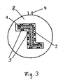
- FIG. 3 shows a Thomasdar Beneficiung the Fig. 2 along AA.
- the shown cold box section 8 can be seen by the nozzles 5 are advantageously always positioned in a consistently small distance 9 to the workpiece surface.
Landscapes
- Chemical & Material Sciences (AREA)
- Engineering & Computer Science (AREA)
- Mechanical Engineering (AREA)
- Thermal Sciences (AREA)
- Physics & Mathematics (AREA)
- Materials Engineering (AREA)
- Crystallography & Structural Chemistry (AREA)
- Metallurgy (AREA)
- Organic Chemistry (AREA)
- Combustion & Propulsion (AREA)
- General Engineering & Computer Science (AREA)
- Heat Treatments In General, Especially Conveying And Cooling (AREA)
- Arc Welding In General (AREA)
- Separation By Low-Temperature Treatments (AREA)
Description
- Die Erfindung betrifft ein Verfahren zum Abkühlen eines Werkstücks, wobei das Werkstück in eine Kühlzone eingebracht wird, welche an eine Kaltbox angrenzt, und wobei ein Kühlmedium der Kaltbox zugeführt wird, wobei das Kühlmedium ein flüssiges Gas oder ein Flüssiggasgemisch umfasst, dessen Verdampfungswärme zur Kühlung der Kaltbox und zur Kühlung der Werkstückoberfläche verwendet wird.
- Ferner bezieht sich die Erfindung auf eine Vorrichtung zum Abkühlen eines Werkstücks mit einer Kaltbox mit einer Zuführung für ein Kühlmedium und mit einer Kühlzone zur Aufnahme des Werkstücks, wobei die Kaltbox und die Kühlzone aneinander grenzen, und wobei die Zuführung für die Einleitung von flüssigem Gas oder einem Flüssiggasgemisch geeignet ausgebildet ist.
- Bekannt sind eine Vielzahl von Verfahren und Vorrichtungen zum Abkühlen. Beispielsweise im Bereich der Wärmebehandlung werden seit Jahrhunderten eine Vielzahl von Verfahren und Vorrichtungen zum Abkühlen und Abschrecken von Werkstücken eingesetzt. Geläufig ist z.B. das Abschrecken in Flüssigkeiten, wie Ölen, Wasser, Emulsionen oder anderen, das Abschrecken in Salzen oder mit Hilfe von Gasen. Gase werden herkömmlich in vielfältiger Form genutzt wie z.B. unter hohem Druck, wodurch die Fähigkeit des Gases Wärmeenergie zu transportieren erhöht wird. Mit dem gleichen Ziel werden Gase nach dem Stand der Technik mit hoher Relativgeschwindigkeit in Kontakt mit der heißen Oberfläche eines abzukühlenden Werkstücks gebracht. Gemäß einem relativ jungen Verfahren, dem sog. "Gasquenching", wird Gas unter hohem Druck und mit hoher Ausströmgeschwindigkeit mit der heißen Oberfläche des abzukühlenden Werkstücks in Kontakt gebracht.
- Das Dokument
GB 1 287 325 A - Das Dokument
US 5,083,436 offenbart eine Vorrichtung zum Abkühlen und Schrumpfen von Werkstücken, die zu einer Verarbeitungsstation auf einer Produktionslinie transportiert werden, die eine Kühlkammer, eine Transporteinrichtung, zumindest eine im wesentlichen vertikal verlaufende Leitung zum Transport einer kryogenen Flüssigkeit aus einem Bad heraus zu einem über dem Bad gelegenen Auslass sowie Schächte zur Speicherung des kryogenen Flüssigkeitsbades, Umlenkbleche zur Verlangsamung des Gegenstromes an kryogenem Gas und eine Klappe aufweist, die das Gas in der Kühlkammer hält. - Als nicht vorveröffentlichter Stand der Technik ist ein Abkühlverfahren für Rohre und andere Halbzeuge (z.B. Stäbe, Profile, Draht u.ä.) bekannt, bei dem die zu kühlenden Werkstücke, als Bündel oder auch einzeln, über ein formangepasstes Düsenfeld, über das Gas auf die Werkstücke geblasen wird, abgekühlt werden, während die Werkstücke durch das Düsenfeld bewegt werden. Dabei kann das Düsenfeld ebenso formangepasst eingehaust sein. Das Abkühlungsergebnis könnte jedoch noch besser sein, besonders für Werkstücke mit einer hohen Ausgangstemperatur von über 550°C.
- Aufgabe der vorliegenden Erfindung ist es, ein verbessertes Verfahren sowie eine Vorrichtung zur Durchführung dieses Verfahrens zur Abkühlung von Werkstücken zur Verfügung zu stellen.
- Die gestellte Aufgabe wird verfahrensseitig dadurch gelöst, dass das Werkstück in eine Kühlzone eingebracht wird, welche an eine Kaltbox angrenzt, und wobei ein Kühlmedium der Kaltbox zugeführt wird, wobei das Kühlmedium ein flüssiges Gas oder ein Flüssiggasgemisch umfasst, dessen Verdampfungswärme zur Kühlung der Kaltbox und zur Kühlung der Werkstückoberfläche verwendet wird, und wobei das Kühlmedium über ein oder mehrere Düse(n) aus der Kaltbox austritt und über die Düse(n) in die Kühlzone geleitet wird.
- Erfindungsgemäß wird das über die Düsen in die Kühlzone eingeleitete Gas - im flüssigen oder gasförmigen Zustand - genutzt, um das Werkstück über Konvektion zu kühlen. Andererseits kühlt das Kühlmedium auch die Kaltbox, die an die Kühlzone angrenzt. Auf diese Weise wird der insbesondere bei hohen Temperaturen dominierende Wärmeübergang durch Strahlung verstärkt.
- Als Kühlmedium wird vorzugsweise ein flüssiges Gas oder ein Gemisch aus Gasen in flüssiger und gasförmiger Form eingesetzt, dessen Verdampfungswärme zur Kühlung der Kaltbox und/oder zur Kühlung der Werkstückoberfläche verwendet wird. Die Umgebung des Werkstücks wird dabei auf eine Temperatur gebracht, die ein besonders effektives Abkühlen des Werkstücks ermöglicht. Besonders für den Fall, dass das Werkstück eine hohe Ausgangstemperatur von über 550°C aufweist, kann mit dem erfindungsgemäßen Verfahren dem Vorherrschen der Wärmeabgabe durch Wärmestrahlung, das in diesem Temperaturbereich gegenüber der Wärmeabgabe über Wärmetransport oder Konvektion vorliegt, Rechnung getragen werden.
- Der Einsatz von flüssigem Gas oder eines Gemisches aus Gasen in flüssiger und gasförmiger Form weist zusätzlich zu der besonders vorteilhaft niedrigen Temperatur, die damit erreicht wird, die Vorteile eines sauberen, umweltfreundlichen Prozesses auf, in dem auf eine Nachreinigung des Werkstücks verzichtet werden kann, keine prozessbedingte Korrosion auftritt und der Prozessablauf aufgrund der guten Dosierbarkeit des Kühlmediums gut steuerbar ist. Insgesamt steht ein höchst effektives Abkühlungsverfahren in einer Vorrichtung mit lediglich geringer räumlicher Ausdehnung zur Verfügung.
- Bevorzugt wird das flüssige Gas oder das Flüssiggasgemisch in der Kaltbox ganz oder teilweise verdampft, wobei die Verdampfungswärme ganz oder teilweise zur Kühlung der Kaltbox verwendet wird.
- Alternativ oder zusätzlich wird das flüssige Gas oder ein Gemisch aus Gasen in flüssiger und gasförmiger Form vorteilhaft ganz oder teilweise direkt auf der Werkstückoberfläche durch Verdampfung wirksam, wobei die Verdampfungswärme ganz oder teilweise zur Kühlung der Werkstückoberfläche verwendet wird.
- Gemäß einer besonders vorteilhaften Weiterbildung der Erfindung wird das Werkstück durch die Kühlzone bewegt, wobei die Kühlzone der Form des Werkstücks angepasst ist, so dass das Kühlmedium einerseits hinreichend lange in der Kühlzone verbleibt, damit die Werkstückoberfläche ausreichend Wärme an das Kühlmedium abgeben kann und andererseits das nun aufgeheizte Kühlmedium mit hoher Geschindigkeit die Kühlzone verlässt.
- Bevorzugt wird das flüssige Gas oder ein Gemisch aus Gasen in flüssiger und gasförmiger Form mit einer hohen Strömungsgeschwindigkeit in die Kühlzone eingebracht.
- Besonders bevorzugt wird als flüssiges Gas flüssiger Stickstoff, flüssiger Wasserstoff , flüssiges Helium oder flüssiges Argon eingesetzt. Gemäß einer vorteilhaften Ausgestaltung wird als Flüssiggasgemisch eine Gemisch aus zwei oder mehr der vorstehend genannten flüssigen Gase eingesetzt.
- Mit besonderem Vorteil werden dem flüssigen Gas oder dem Flüssiggasgemisch eine oder mehrere weitere Komponenten zugesetzt. Beispielsweise werden dem flüssigen Gas oder Flüssiggasgemisch Kohlendioxid und/oder Methan beigemischt.
- Vorrichtungsseitig wird die gestellte Aufgabe durch eine Vorrichtung zum Abkühlen eines Werkstücks mit einer Kaltbox mit einer Zuführung für ein Kühlmedium und mit einer Kühlzone zur Aufnahme des Werkstücks gelöst, wobei die Kaltbox und die Kühlzone aneinander grenzen, und wobei die Zuführung für die Einleitung von flüssigem Gas oder einem Flüssiggasgemisch geeignet ausgebildet ist., und welche dadurch gekennzeichnet ist, dass ein oder mehrere Düsen so an der Kaltbox angebracht sind, dass das Kühlmedium über die Düse(n) aus der Kaltbox austritt und über die Düse(n) in die Kühlzone geleitet wird. Durch diese Gestaltung wird es ermöglicht, dass das Kühlmedium schnell mit dem Werkstück in Wärmeaustausch tritt und die von dem Werkstück ausgehende Wärmestrahlung von der Kaltbox aufgenommen wird, wobei die Kaltbox annähernd die Temperatur des flüssigen Gases oder Flüssiggasgemisches aufweist.
- Bevorzugt ist die Kaltbox als Einrichtung zur Verdampfung des flüssigen Gases oder des Flüssiggasgemisches vorgesehen.
- Besonders bevorzugt ist die Kaltbox der Form des Werkstücks angepasst ausgebildet, so dass lediglich ein sehr geringer Abstand zwischen den Düsen für das Kühlmedium und der Werkstückoberfläche vorgesehen ist. Die Kaltbox und die Kühlzone grenzen von Vorteil aneinander an, so dass einerseits das über die Düsen aus der Kaltbox austretende Kühlmedium schnell mit dem Werkstück in Wärmeaustausch tritt und andererseits die von dem Werkstück ausgehende Wärmestrahlung von der Kaltbox aufgenommen wird. Die Kaltbox ist hierzu vorzugsweise so ausgebildet, dass diese das Werkstück an mehreren Seiten umgibt.
- Gemäß einer besonders vorteilhaften Weiterbildung der Erfindung ist die Kaltbox in zwei oder mehr Kaltboxabschnitte unterteilt, die jeweils durch einen Spalt im Düsenbereich voneinander beabstandet sind.
- Desweiteren ist die Verwendung der vorstehend beschriebenen Vorrichtung zur Abkühlung metallischer Werkstücke, insbesondere zur Abkühlung von Rohren oder anderen Halbzeugen wie Stäben, Profilen oder Draht Gegenstand der vorliegenden Erfindung.
- Die Erfindung bietet ein höchst effektives Abkühl- oder Abschreckverfahren, insbesondere für heiße Metallteile. Bei hohen Temperaturen erfolgt die Wärmeübertragung hauptsächlich durch Wärmestrahlung. Erfindungsgemäß wird die Kaltbox durch das zugeführte Flüssiggas auf niedriger Temperatur gehalten. Unmittelbar angrenzend an die Kaltbox befindet sich die Kühlzone zur Aufnahme des Werkstücks. Die Temperaturdifferenz zwischen der Werkstückoberfläche und der Kaltbox wird durch die Kühlung der Kaltbox maximiert, so dass eine optimale Abkühlung durch Strahlung erfolgt. Zudem wird das Kühlmedium durch Düsenöffnungen in der Kaltbox auf die Werkstückoberfläche geführt. Diese Strömung bewirkt eine zusätzliche Abkühlung durch Konvektion. Insgesamt bietet die Erfindung damit eine besonders effiziente Ausnutzung der verschiedenen Wärmeübertragungsmechanismen.
- Die Erfindung sowie weitere Ausgestaltungen der Erfindung werden im Folgenden anhand der in den Figuren dargestellten Ausführungsbeispiele näher erläutert. Im Einzelnen zeigen:
- Fig. 1
- eine schematische Darstellung einer erfindungsgemäßen Kaltbox mit Werkstück,
- Fig. 2
- eine schematische Dastellung einer erfindungsgemäßen Kaltbox, die in drei Kaltboxabschnitte unterteilt ist und
- Fig. 3
- eine schematische Schnittdarstelltung der
Fig. 2 entlang A-A. - Die
Figur 1 zeigt ein Werkstück 1, hier ein Rohr 1, das entlang der durch den Pfeil 2 angezeigten Richtung durch die Kaltbox 3 bewegt wird, von der das Rohr 1 umhüllt wird. Die Kaltbox 3 ist der Form des Rohres 1 angepasst. Flüssiges Gas, hier z.B. flüssiger Stickstoff wird über die Zuführung 4 in die Kaltbox 3 kontinuierlich eingebracht. Je nach Erfordernis tritt über das Düsenfeld, das durch die Düsen 5 gebildet wird, das Gas noch als flüssiges Gas aus und wird unter Nutzung der Verdampfungswärme als sehr kaltes Kühlmedium mit hoher Strömungsgeschwindigkeit auf der Oberfläche des Werkstücks 1 wirksam. - Im anderen Fall wirkt die Kaltbox 3 als Verdampfer. Die Verdampfungswärme wird in diesem Fall dann zum Abkühlen und Kalthalten der Kaltbox 3 genutzt.
- Bei beiden Varianten hat die Kaltbox 3 annähernd die Temperatur des flüssigen Gases. Das bedeutet, dass die Temperaturdifferenz zwischen Werkstückoberfläche und Kaltboxoberfläche dauerhaft sehr groß ist und es zu einer entsprechenden Abkühlung des Werkstücks 1 über den Strahlungsmechanismus kommt, der wirksam durch den Wärmetransport infolge der ursprünglich sehr kalten Gasströmung 6 unterstützt wird.
- Die Wirkung dieses Verfahrens kann so optimiert werden, dass die Obergrenze für die abgeführte Wärmemenge nicht mehr durch die zugeführte Menge an flüssigem Gas und dessen thermische Eigenschaften bestimmt wird, sondern der Wärmeleitungsmechanismus des Werkstücks 1 die Obergrenze vorgibt.
- Für das in der
Figur 1 dargestellte Ausführungsbeispiel können folgende beispielhaften Werte angegeben werden: Ein Stahlrohr 1 mit einem Durchmesser von 60 mm und einer Wanddicke von 3 mm wird mit einer Geschwindigkeit von 5 m/s durch die Kaltbox 3 bewegt. Die Ausgangstemperatur des Stahlrohrs 1 beträgt 1050°C. Die Endtemperatur nach der Abkühlung beträt z.B. 700°C. Dieses Endergebnis wird durch den Einsatz von flüssigem Stickstoff als Kühlmedium in einer Menge von 300 kg/h und einem Einspeisedruck von 3 bar erreicht. Das Düsenfeld weist hierbei 20 Düsen 5 mit einem Durchmesser von je 3 mm auf. Die Gesamtlänge der Kaltbox 3 beträgt 1200 mm. - Ein weiteres Ausführungsbeispiel zeigt die
Figur 2 . Hier ist die Kaltbox 3 in drei Kaltboxabschnitte 8 geteilt, zwischenen denen je über den Spalt 7 Gas in Form einer Gasströmung 6 austritt. Die Bewegung des Werkstücks erfolgt wieder in die durch den Pfeil 2 angezeigte Richtung. Das Werkstück 1 ist in diesem Beispiel ein Kupferprofil 1 mit einer größten Breite von 35 mm, das eine Strangpresse mit 100 m/min und einer Temperatur von 750°C verlässt. Die Endtemperatur nach der Abkühlung soll 200°C betragen. Das Kupferprofil 1 wird durch die in derFigur 2 dargestellte Vorrichtung bewegt und dabei mit Hilfe eines über die Zuführung 4 eingespeisten und über die Düsen 5 in den einzelnen Kaltboxabschnitten 8 abgegebenen Flüssiggasgemisches abgekühlt. Dabei kommt entweder flüssiges Helium oder als kostengünstigere Variante ein Gemisch aus 95% flüssigem Stickstoff und 5% gasförmigem Wasserstoff zum Einsatz. Der Gasverbrauch beträgt 350 kg/h. - Aufgrund der anderen Temperaturverhältnisse spielt in diesem Beispiel der Wärmetransport mit der Gasströmung 6 eine größere Rolle als in dem Beispiel der
Figur 1 . Um die Strömungsverhältnisse für die Gasströmung 6 zu optimieren und den Gasaustritt trotz engster Spalte 9 zu gewährleisten, wurde hier die Kaltbox 3 in drei Kaltboxabschnitte 8 geteilt. Die Abstände 7 zwischen den Kaltboxabschnitten 8 könne je nach den konkreten Erfordernissen verschiedener Anwendungsfälle verändert und optimiert werden. - Die
Figur 3 zeigt eine Schnittdarstelltung derFig. 2 entlang A-A. Hier ist besonders gut die dem Werkstück 1 angepasste Form der Kaltbox 3 bzw. des gezeigten Kaltboxabschnittes 8 zu erkennen, durch die die Düsen 5 vorteilhaft immer in einem gleichbleibend geringen Abstand 9 zur Werkstückoberfläche positioniert sind.
Claims (15)
- Verfahren zum Abkühlen eines Werkstücks (1), wobei das Werkstück (1) in eine Kühlzone (10) eingebracht wird, welche an eine Kaltbox (3) angrenzt, und wobei ein Kühlmedium der Kaltbox (3) zugeführt wird, wobei das Kühlmedium ein flüssiges Gas oder ein Flüssiggasgemisch umfasst, dessen Verdampfungswärme zur Kühlung der Kaltbox (3) und zur Kühlung der Werkstückoberfläche (1) verwendet wird, dadurch gekennzeichnet, dass das Kühlmedium über ein oder mehrere Düse(n) (5) aus der Kaltbox (3) austritt und über die Düse(n) (5) in die Kühlzone (10) geleitet wird.
- Verfahren nach Anspruch 1, dadurch gekennzeichnet, dass das flüssige Gas oder das Flüssiggasgemisch in der Kaltbox (3) ganz oder teilweise verdampft wird, wobei die Verdampfungswärme ganz oder teilweise zur Kühlung der Kaltbox (3) verwendet wird.
- Verfahren nach Anspruch 1 oder 2, dadurch gekennzeichnet, dass das flüssige Gas oder das Flüssiggasgemisch in der Kühlzone (10) ganz oder teilweise verdampft wird, wobei die Verdampfungswärme ganz oder teilweise zur Kühlung der Werkstückoberfläche verwendet wird.
- Verfahren nach einem der Ansprüche 1 bis 3, dadurch gekennzeichnet, dass das Werkstück (1) während der Abkühlung durch die Kühlzone (10) bewegt wird.
- Verfahren nach einem der Ansprüche 1 bis 4, dadurch gekennzeichnet, dass die Kühlzone (10) der Form des Werkstücks (1) angepasst ist, so dass das Kühlmedium lediglich einen sehr geringen Weg (9) zwischen der oder den Düsen (5), durch die das Kühlmedium eingeleitet wird, und der Werkstückoberfläche zurücklegt.
- Verfahren nach einem der Ansprüche 1 bis 5, dadurch gekennzeichnet, dass das flüssige Gas oder Flüssiggasgemisch mit einer hohen Strömungsgeschwindigkeit in die Kühlzone (10) eingebracht wird.
- Verfahren nach einem der Ansprüche 1 bis 6, dadurch gekennzeichnet, dass als flüssiges Gas flüssiger Stickstoff, flüssiger Wasserstoff , flüssiges Helium oder flüssiges Argon eingesetzt wird.
- Verfahren nach einem der Ansprüche 1 bis 7, dadurch gekennzeichnet, dass als Flüssiggasgemisch eine Gemisch aus zwei oder mehr der in Anspruch 7 genannten flüssigen Gase eingesetzt wird.
- Verfahren nach Anspruch 7 oder 8, dadurch gekennzeichnet, dass dem flüssigen Gas oder dem Flüssiggasgemisch eine oder mehrere weitere Komponenten zugesetzt werden.
- Verfahren nach Anspruch 9, dadurch gekennzeichnet, dass dem flüssigen Gas oder Flüssiggasgemisch Kohlendioxid und/oder Methan beigemischt werden.
- Vorrichtung zum Abkühlen eines Werkstücks (1) mit einer Kaltbox (3) mit einer Zuführung (4) für ein Kühlmedium und mit einer Kühlzone (10) zur Aufnahme des Werkstücks (1), wobei die Kaltbox (3) und die Kühlzone (10) aneinander grenzen, und wobei die Zuführung (4) für die Einleitung von flüssigem Gas oder einem Flüssiggasgemisch geeignet ausgebildet ist, dadurch gekennzeichnet, dass ein oder mehrere Düsen (5) so an der Kaltbox (3) angebracht sind, dass das Kühlmedium über die Düse(n) (5) aus der Kaltbox (3) austritt und über die Düse(n) (5) in die Kühlzone (10) geleitet wird.
- Vorrichtung nach Anspruch 11, dadurch gekennzeichnet, dass die Kaltbox (3) als Einrichtung zur Verdampfung des flüssigen Gases oder des Flüssiggasgemisches vorgesehen ist.
- Vorrichtung nach Anspruch 11 oder 12, dadurch gekennzeichnet, dass die Kaltbox (3) der Form des Werkstücks (1) angepasst ausgebildet ist, so dass lediglich ein sehr geringer Abstand (9) zwischen den Düsen (5) für das Kühlmedium und der Werkstückoberfläche vorgesehen ist.
- Vorrichtung nach einem der Ansprüche 11 bis 13, dadurch gekennzeichnet, dass die Kaltbox (3) in zwei oder mehr Kaltboxabschnitte (8) unterteilt ist, die jeweils durch einen Spalt (7) im Düsenbereich voneinander beabstandet sind.
- Verwendung der Vorrichtung nach einem der Ansprüche 11 bis 14 zur Abkühlung metallischer Werkstücke (1), insbesondere zur Abkühlung von Rohren oder anderen Halbzeugen wie Stäben, Profilen oder Draht.
Priority Applications (1)
| Application Number | Priority Date | Filing Date | Title |
|---|---|---|---|
| PL06015701T PL1837410T3 (pl) | 2006-03-21 | 2006-07-27 | Sposób i urządzenie do szybkiego schładzania przedmiotów obrabianych |
Applications Claiming Priority (1)
| Application Number | Priority Date | Filing Date | Title |
|---|---|---|---|
| DE102006012985A DE102006012985A1 (de) | 2006-03-21 | 2006-03-21 | Verfahren und Vorrichtung zum schnellen Abkühlen von Werkstücken |
Publications (2)
| Publication Number | Publication Date |
|---|---|
| EP1837410A1 EP1837410A1 (de) | 2007-09-26 |
| EP1837410B1 true EP1837410B1 (de) | 2009-08-26 |
Family
ID=37084713
Family Applications (1)
| Application Number | Title | Priority Date | Filing Date |
|---|---|---|---|
| EP06015701A Not-in-force EP1837410B1 (de) | 2006-03-21 | 2006-07-27 | Verfahren und Vorrichtung zum schnellen Abkühlen von Werkstücken |
Country Status (8)
| Country | Link |
|---|---|
| US (1) | US20070220906A1 (de) |
| EP (1) | EP1837410B1 (de) |
| AT (1) | ATE440970T1 (de) |
| BR (1) | BRPI0700848A (de) |
| DE (2) | DE102006012985A1 (de) |
| DK (1) | DK1837410T3 (de) |
| ES (1) | ES2332811T3 (de) |
| PL (1) | PL1837410T3 (de) |
Cited By (1)
| Publication number | Priority date | Publication date | Assignee | Title |
|---|---|---|---|---|
| WO2024256545A1 (en) * | 2023-06-14 | 2024-12-19 | L'air Liquide, Societe Anonyme Pour L'etude Et L'exploitation Des Procedes Georges Claude | Production of an aluminium strand |
Families Citing this family (5)
| Publication number | Priority date | Publication date | Assignee | Title |
|---|---|---|---|---|
| EP1842932A1 (de) * | 2006-04-06 | 2007-10-10 | Linde Aktiengesellschaft | Methode um Röhren abzukühlen |
| CN107262700A (zh) * | 2017-08-03 | 2017-10-20 | 新兴铸管股份有限公司 | 铸管冷却系统 |
| CN107385171B (zh) * | 2017-09-21 | 2019-03-29 | 江苏南钢通恒特材科技有限公司 | 喷淋淬火装置及钢棒生产线 |
| CN108981403A (zh) * | 2018-08-09 | 2018-12-11 | 唐山国丰钢铁有限公司 | 一种应用于冶金上的冷却装置 |
| CN111360092A (zh) * | 2020-03-25 | 2020-07-03 | 合肥市华佳鑫自动化科技有限公司 | 一种用于铝型材挤出生产线降温装置 |
Family Cites Families (20)
| Publication number | Priority date | Publication date | Assignee | Title |
|---|---|---|---|---|
| US1442953A (en) * | 1922-02-13 | 1923-01-23 | Kehoe Josephine Griffith | Bottle-vending machine |
| US1693995A (en) * | 1925-09-02 | 1928-12-04 | John W Ladd Co | Bottle cooler |
| US1820074A (en) * | 1928-12-03 | 1931-08-25 | Seiberling Rubber Co | Means for cooling mill rolls |
| US2153742A (en) * | 1937-03-18 | 1939-04-11 | Chester J Conn | Apparatus for quick freezing of food products |
| US2487821A (en) * | 1944-06-10 | 1949-11-15 | Linde Air Prod Co | Method of and apparatus for cooling and dispensing objects |
| US2998465A (en) * | 1957-10-09 | 1961-08-29 | Monsanto Chemicals | Quench system |
| US3345828A (en) * | 1965-06-11 | 1967-10-10 | Air Prod & Chem | Parallel flow cryogenic freezer |
| CH438594A (de) * | 1966-05-31 | 1967-06-30 | Concast Ag | Verfahren und Vorrichtung zum Kühlen von Stranggussmaterial |
| US3403530A (en) * | 1966-10-18 | 1968-10-01 | Colonial Sugar Refining Co | Liquid carbon dioxide refrigeration |
| US3479833A (en) * | 1968-02-06 | 1969-11-25 | Du Pont | Method of extracting heat from articles with an ebullient liquid freezant |
| BE748164A (fr) * | 1969-04-03 | 1970-08-31 | Heye Hermann Fa | Procede pour influencer la temperature des verres fondus entre la cuve de vitrification et l'anneau de sortie de gouttes d'un dispositif d'alimentation |
| US3611745A (en) * | 1969-11-24 | 1971-10-12 | Ralph Hamill | Freezing system |
| GB1287325A (en) | 1970-06-03 | 1972-08-31 | British Oxygen Co Ltd | Apparatus for cooling a series of workpieces |
| US5083436A (en) | 1990-06-14 | 1992-01-28 | Vacuum Barrier Corporation | Workpiece chilling and shrinking |
| US5329779A (en) * | 1993-02-09 | 1994-07-19 | C.V.G. Siderurgica Del Orinoco, C.A. | Method and apparatus for cooling workpieces |
| SE512588C2 (sv) * | 1998-08-06 | 2000-04-03 | Aga Ab | Metod och anordning för punktkylning av yta |
| US7654100B2 (en) * | 2001-04-26 | 2010-02-02 | Rini Technologies, Inc. | Method and apparatus for high heat flux heat transfer |
| FR2844582B1 (fr) * | 2002-09-16 | 2005-06-17 | H Raymond Guyomarc | Systeme de refroidissement regulateur pour la maitrise des temperatures de parois soumises a des productions thermiques |
| FR2844809B1 (fr) * | 2002-09-20 | 2007-06-29 | Air Liquide | Procede de refroidissement rapide de pieces par transfert convectif et radiatif |
| EP1842932A1 (de) * | 2006-04-06 | 2007-10-10 | Linde Aktiengesellschaft | Methode um Röhren abzukühlen |
-
2006
- 2006-03-21 DE DE102006012985A patent/DE102006012985A1/de not_active Withdrawn
- 2006-07-27 DK DK06015701T patent/DK1837410T3/da active
- 2006-07-27 EP EP06015701A patent/EP1837410B1/de not_active Not-in-force
- 2006-07-27 PL PL06015701T patent/PL1837410T3/pl unknown
- 2006-07-27 DE DE502006004656T patent/DE502006004656D1/de active Active
- 2006-07-27 AT AT06015701T patent/ATE440970T1/de active
- 2006-07-27 ES ES06015701T patent/ES2332811T3/es active Active
-
2007
- 2007-03-20 US US11/688,767 patent/US20070220906A1/en not_active Abandoned
- 2007-03-21 BR BRPI0700848-1A patent/BRPI0700848A/pt not_active IP Right Cessation
Cited By (1)
| Publication number | Priority date | Publication date | Assignee | Title |
|---|---|---|---|---|
| WO2024256545A1 (en) * | 2023-06-14 | 2024-12-19 | L'air Liquide, Societe Anonyme Pour L'etude Et L'exploitation Des Procedes Georges Claude | Production of an aluminium strand |
Also Published As
| Publication number | Publication date |
|---|---|
| ATE440970T1 (de) | 2009-09-15 |
| PL1837410T3 (pl) | 2010-02-26 |
| US20070220906A1 (en) | 2007-09-27 |
| EP1837410A1 (de) | 2007-09-26 |
| ES2332811T3 (es) | 2010-02-12 |
| DE502006004656D1 (de) | 2009-10-08 |
| DK1837410T3 (da) | 2009-12-21 |
| DE102006012985A1 (de) | 2007-10-11 |
| BRPI0700848A (pt) | 2008-01-15 |
Similar Documents
| Publication | Publication Date | Title |
|---|---|---|
| DE69431178T3 (de) | Verfahren zur thermischen Oberflächenbehandlung eines Stranges | |
| EP0876856B1 (de) | Hochleistungs-Drahtwalzwerk | |
| EP0001391B1 (de) | Vorrichtung in Form eines doppelwandigen Rohres zum Kühlen von Endlosprofilen | |
| DE102016102093B3 (de) | Durchlaufkühlvorrichtung und Verfahren zum Abkühlen eines Metallbandes | |
| DE102006056683A1 (de) | Verfahren und Vorrichtung zum Stranggießen | |
| DE102004037491B4 (de) | Vorrichtung und Verfahren zum Vorspannen von länglichen, hohlen Gegenständen aus Glas und Verwendung der Vorrichtung | |
| DE2219406A1 (de) | Metallhärtungsverfahren und nach diesem Verfahren hergestelltes Hartmetall | |
| US20070220906A1 (en) | Method and Device for Rapid Cooling of Work Pieces | |
| AT391099B (de) | Verfahren zum autogenen brennschneiden mit sauerstoff | |
| WO2009153145A1 (de) | Vorrichtung für das mischen von flüssigkeit und dampf sowie verfahren für das verdampfen eines fluids mit der mischung | |
| DE3234863A1 (de) | Verfahren und vorrichtung zum blankgluehen von metallischen werkstuecken mit stickstoff als schutzgas | |
| DE102005001806A1 (de) | Verfahren zum Kaltwalzen von metallischem Walzgut | |
| DE69319285T2 (de) | Verfahren zum Wärmebehandeln von Walzdraht | |
| DE2951818A1 (de) | Verfahren zur fortlaufenden kuehlbehandlung von metallischen werkstuecken, insbesondere blechen | |
| DE102010051047A1 (de) | Verfahren zum Temperieren eines Formwerkzeugs | |
| DE60015432T2 (de) | Vorrichtung und Verfahren zum Wärmebehandeln von metallischem Material | |
| DE102023108620B4 (de) | Vorrichtung zum Kühlen bandförmiger Werkstücke | |
| DE2929401A1 (de) | Verfahren zum walzen von in der waerme zur oxidation neigenden metallbloecken zu rohren | |
| DE102012007292A1 (de) | Verfahren und Behandlungsstrecke zum abschnittsweise Veredeln eines Metallprodukts | |
| DE19718530B4 (de) | Verfahren zum Kühlen von walzwarmem Walzgut und Vorrichtung zur Durchführung des Verfahrens und Verwendung der Vorrichtung | |
| EP3020491A1 (de) | Verfahren zum Umformen von Aluminiumblechen | |
| DE2605826A1 (de) | Verfahren und vorrichtung zum patentieren von stahldraehten | |
| EP2908960A2 (de) | Vorrichtung zur wärmeübertragung bei der herstellung von langgestrecktem stranggut | |
| EP0597560B1 (de) | Vorrichtung zum Kühlen von Profilen | |
| DE3825839A1 (de) | Vorrichtung zum kuehlen und zum hydraulischen transport von unsymmetrischen walzprofilen |
Legal Events
| Date | Code | Title | Description |
|---|---|---|---|
| PUAI | Public reference made under article 153(3) epc to a published international application that has entered the european phase |
Free format text: ORIGINAL CODE: 0009012 |
|
| AK | Designated contracting states |
Kind code of ref document: A1 Designated state(s): AT BE BG CH CY CZ DE DK EE ES FI FR GB GR HU IE IS IT LI LT LU LV MC NL PL PT RO SE SI SK TR |
|
| AX | Request for extension of the european patent |
Extension state: AL BA HR MK YU |
|
| RAP1 | Party data changed (applicant data changed or rights of an application transferred) |
Owner name: LINDE AKTIENGESELLSCHAFT |
|
| 17P | Request for examination filed |
Effective date: 20071106 |
|
| 17Q | First examination report despatched |
Effective date: 20071206 |
|
| R17C | First examination report despatched (corrected) |
Effective date: 20071213 |
|
| AKX | Designation fees paid |
Designated state(s): AT BE BG CH CY CZ DE DK EE ES FI FR GB GR HU IE IS IT LI LT LU LV MC NL PL PT RO SE SI SK TR |
|
| GRAP | Despatch of communication of intention to grant a patent |
Free format text: ORIGINAL CODE: EPIDOSNIGR1 |
|
| GRAS | Grant fee paid |
Free format text: ORIGINAL CODE: EPIDOSNIGR3 |
|
| GRAA | (expected) grant |
Free format text: ORIGINAL CODE: 0009210 |
|
| RAP1 | Party data changed (applicant data changed or rights of an application transferred) |
Owner name: LINDE AG |
|
| AK | Designated contracting states |
Kind code of ref document: B1 Designated state(s): AT BE BG CH CY CZ DE DK EE ES FI FR GB GR HU IE IS IT LI LT LU LV MC NL PL PT RO SE SI SK TR |
|
| REG | Reference to a national code |
Ref country code: GB Ref legal event code: FG4D Free format text: NOT ENGLISH |
|
| REG | Reference to a national code |
Ref country code: CH Ref legal event code: EP |
|
| REG | Reference to a national code |
Ref country code: IE Ref legal event code: FG4D Free format text: LANGUAGE OF EP DOCUMENT: GERMAN |
|
| REF | Corresponds to: |
Ref document number: 502006004656 Country of ref document: DE Date of ref document: 20091008 Kind code of ref document: P |
|
| REG | Reference to a national code |
Ref country code: RO Ref legal event code: EPE |
|
| REG | Reference to a national code |
Ref country code: SE Ref legal event code: TRGR |
|
| REG | Reference to a national code |
Ref country code: DK Ref legal event code: T3 |
|
| LTIE | Lt: invalidation of european patent or patent extension |
Effective date: 20090826 |
|
| PG25 | Lapsed in a contracting state [announced via postgrant information from national office to epo] |
Ref country code: IS Free format text: LAPSE BECAUSE OF FAILURE TO SUBMIT A TRANSLATION OF THE DESCRIPTION OR TO PAY THE FEE WITHIN THE PRESCRIBED TIME-LIMIT Effective date: 20091226 Ref country code: LT Free format text: LAPSE BECAUSE OF FAILURE TO SUBMIT A TRANSLATION OF THE DESCRIPTION OR TO PAY THE FEE WITHIN THE PRESCRIBED TIME-LIMIT Effective date: 20090826 |
|
| REG | Reference to a national code |
Ref country code: ES Ref legal event code: FG2A Ref document number: 2332811 Country of ref document: ES Kind code of ref document: T3 |
|
| PG25 | Lapsed in a contracting state [announced via postgrant information from national office to epo] |
Ref country code: SI Free format text: LAPSE BECAUSE OF FAILURE TO SUBMIT A TRANSLATION OF THE DESCRIPTION OR TO PAY THE FEE WITHIN THE PRESCRIBED TIME-LIMIT Effective date: 20090826 Ref country code: LV Free format text: LAPSE BECAUSE OF FAILURE TO SUBMIT A TRANSLATION OF THE DESCRIPTION OR TO PAY THE FEE WITHIN THE PRESCRIBED TIME-LIMIT Effective date: 20090826 |
|
| REG | Reference to a national code |
Ref country code: PL Ref legal event code: T3 |
|
| PG25 | Lapsed in a contracting state [announced via postgrant information from national office to epo] |
Ref country code: PT Free format text: LAPSE BECAUSE OF FAILURE TO SUBMIT A TRANSLATION OF THE DESCRIPTION OR TO PAY THE FEE WITHIN THE PRESCRIBED TIME-LIMIT Effective date: 20091228 Ref country code: BG Free format text: LAPSE BECAUSE OF FAILURE TO SUBMIT A TRANSLATION OF THE DESCRIPTION OR TO PAY THE FEE WITHIN THE PRESCRIBED TIME-LIMIT Effective date: 20091126 Ref country code: CY Free format text: LAPSE BECAUSE OF FAILURE TO SUBMIT A TRANSLATION OF THE DESCRIPTION OR TO PAY THE FEE WITHIN THE PRESCRIBED TIME-LIMIT Effective date: 20090826 |
|
| REG | Reference to a national code |
Ref country code: IE Ref legal event code: FD4D |
|
| REG | Reference to a national code |
Ref country code: HU Ref legal event code: AG4A Ref document number: E006953 Country of ref document: HU |
|
| PG25 | Lapsed in a contracting state [announced via postgrant information from national office to epo] |
Ref country code: EE Free format text: LAPSE BECAUSE OF FAILURE TO SUBMIT A TRANSLATION OF THE DESCRIPTION OR TO PAY THE FEE WITHIN THE PRESCRIBED TIME-LIMIT Effective date: 20090826 Ref country code: IE Free format text: LAPSE BECAUSE OF FAILURE TO SUBMIT A TRANSLATION OF THE DESCRIPTION OR TO PAY THE FEE WITHIN THE PRESCRIBED TIME-LIMIT Effective date: 20090826 |
|
| REG | Reference to a national code |
Ref country code: SK Ref legal event code: T3 Ref document number: E 6685 Country of ref document: SK |
|
| PLBE | No opposition filed within time limit |
Free format text: ORIGINAL CODE: 0009261 |
|
| STAA | Information on the status of an ep patent application or granted ep patent |
Free format text: STATUS: NO OPPOSITION FILED WITHIN TIME LIMIT |
|
| 26N | No opposition filed |
Effective date: 20100527 |
|
| PG25 | Lapsed in a contracting state [announced via postgrant information from national office to epo] |
Ref country code: GR Free format text: LAPSE BECAUSE OF FAILURE TO SUBMIT A TRANSLATION OF THE DESCRIPTION OR TO PAY THE FEE WITHIN THE PRESCRIBED TIME-LIMIT Effective date: 20091127 |
|
| PGFP | Annual fee paid to national office [announced via postgrant information from national office to epo] |
Ref country code: HU Payment date: 20100712 Year of fee payment: 5 |
|
| PGFP | Annual fee paid to national office [announced via postgrant information from national office to epo] |
Ref country code: DK Payment date: 20100712 Year of fee payment: 5 |
|
| PG25 | Lapsed in a contracting state [announced via postgrant information from national office to epo] |
Ref country code: MC Free format text: LAPSE BECAUSE OF NON-PAYMENT OF DUE FEES Effective date: 20100731 |
|
| PGFP | Annual fee paid to national office [announced via postgrant information from national office to epo] |
Ref country code: BE Payment date: 20100714 Year of fee payment: 5 |
|
| PG25 | Lapsed in a contracting state [announced via postgrant information from national office to epo] |
Ref country code: IT Free format text: LAPSE BECAUSE OF FAILURE TO SUBMIT A TRANSLATION OF THE DESCRIPTION OR TO PAY THE FEE WITHIN THE PRESCRIBED TIME-LIMIT Effective date: 20090826 |
|
| BERE | Be: lapsed |
Owner name: LINDE A.G. Effective date: 20110731 |
|
| REG | Reference to a national code |
Ref country code: DK Ref legal event code: EBP |
|
| PG25 | Lapsed in a contracting state [announced via postgrant information from national office to epo] |
Ref country code: BE Free format text: LAPSE BECAUSE OF NON-PAYMENT OF DUE FEES Effective date: 20110731 Ref country code: HU Free format text: LAPSE BECAUSE OF NON-PAYMENT OF DUE FEES Effective date: 20110728 |
|
| PG25 | Lapsed in a contracting state [announced via postgrant information from national office to epo] |
Ref country code: DK Free format text: LAPSE BECAUSE OF NON-PAYMENT OF DUE FEES Effective date: 20110731 |
|
| PG25 | Lapsed in a contracting state [announced via postgrant information from national office to epo] |
Ref country code: LU Free format text: LAPSE BECAUSE OF NON-PAYMENT OF DUE FEES Effective date: 20100727 |
|
| PGFP | Annual fee paid to national office [announced via postgrant information from national office to epo] |
Ref country code: RO Payment date: 20130612 Year of fee payment: 8 |
|
| PGFP | Annual fee paid to national office [announced via postgrant information from national office to epo] |
Ref country code: SK Payment date: 20130709 Year of fee payment: 8 Ref country code: CZ Payment date: 20130711 Year of fee payment: 8 |
|
| PGFP | Annual fee paid to national office [announced via postgrant information from national office to epo] |
Ref country code: ES Payment date: 20140611 Year of fee payment: 9 Ref country code: TR Payment date: 20140620 Year of fee payment: 9 |
|
| PGFP | Annual fee paid to national office [announced via postgrant information from national office to epo] |
Ref country code: PL Payment date: 20140616 Year of fee payment: 9 |
|
| PGFP | Annual fee paid to national office [announced via postgrant information from national office to epo] |
Ref country code: FI Payment date: 20140710 Year of fee payment: 9 Ref country code: NL Payment date: 20140710 Year of fee payment: 9 Ref country code: CH Payment date: 20140714 Year of fee payment: 9 Ref country code: DE Payment date: 20140724 Year of fee payment: 9 |
|
| PGFP | Annual fee paid to national office [announced via postgrant information from national office to epo] |
Ref country code: SE Payment date: 20140711 Year of fee payment: 9 Ref country code: AT Payment date: 20140626 Year of fee payment: 9 Ref country code: GB Payment date: 20140723 Year of fee payment: 9 Ref country code: FR Payment date: 20140708 Year of fee payment: 9 |
|
| REG | Reference to a national code |
Ref country code: SK Ref legal event code: MM4A Ref document number: E 6685 Country of ref document: SK Effective date: 20140727 |
|
| PG25 | Lapsed in a contracting state [announced via postgrant information from national office to epo] |
Ref country code: SK Free format text: LAPSE BECAUSE OF NON-PAYMENT OF DUE FEES Effective date: 20140727 Ref country code: RO Free format text: LAPSE BECAUSE OF NON-PAYMENT OF DUE FEES Effective date: 20140727 Ref country code: CZ Free format text: LAPSE BECAUSE OF NON-PAYMENT OF DUE FEES Effective date: 20140727 |
|
| REG | Reference to a national code |
Ref country code: DE Ref legal event code: R119 Ref document number: 502006004656 Country of ref document: DE |
|
| REG | Reference to a national code |
Ref country code: CH Ref legal event code: PL |
|
| REG | Reference to a national code |
Ref country code: SE Ref legal event code: EUG |
|
| REG | Reference to a national code |
Ref country code: AT Ref legal event code: MM01 Ref document number: 440970 Country of ref document: AT Kind code of ref document: T Effective date: 20150727 |
|
| GBPC | Gb: european patent ceased through non-payment of renewal fee |
Effective date: 20150727 |
|
| REG | Reference to a national code |
Ref country code: NL Ref legal event code: MM Effective date: 20150801 |
|
| PG25 | Lapsed in a contracting state [announced via postgrant information from national office to epo] |
Ref country code: CH Free format text: LAPSE BECAUSE OF NON-PAYMENT OF DUE FEES Effective date: 20150731 Ref country code: GB Free format text: LAPSE BECAUSE OF NON-PAYMENT OF DUE FEES Effective date: 20150727 Ref country code: DE Free format text: LAPSE BECAUSE OF NON-PAYMENT OF DUE FEES Effective date: 20160202 Ref country code: LI Free format text: LAPSE BECAUSE OF NON-PAYMENT OF DUE FEES Effective date: 20150731 |
|
| REG | Reference to a national code |
Ref country code: FR Ref legal event code: ST Effective date: 20160331 |
|
| PG25 | Lapsed in a contracting state [announced via postgrant information from national office to epo] |
Ref country code: FR Free format text: LAPSE BECAUSE OF NON-PAYMENT OF DUE FEES Effective date: 20150731 Ref country code: SE Free format text: LAPSE BECAUSE OF NON-PAYMENT OF DUE FEES Effective date: 20150728 Ref country code: NL Free format text: LAPSE BECAUSE OF NON-PAYMENT OF DUE FEES Effective date: 20150801 Ref country code: AT Free format text: LAPSE BECAUSE OF NON-PAYMENT OF DUE FEES Effective date: 20150727 Ref country code: FI Free format text: LAPSE BECAUSE OF NON-PAYMENT OF DUE FEES Effective date: 20150727 |
|
| REG | Reference to a national code |
Ref country code: ES Ref legal event code: FD2A Effective date: 20160826 |
|
| PG25 | Lapsed in a contracting state [announced via postgrant information from national office to epo] |
Ref country code: PL Free format text: LAPSE BECAUSE OF NON-PAYMENT OF DUE FEES Effective date: 20150727 |
|
| PG25 | Lapsed in a contracting state [announced via postgrant information from national office to epo] |
Ref country code: ES Free format text: LAPSE BECAUSE OF NON-PAYMENT OF DUE FEES Effective date: 20150728 |
|
| PG25 | Lapsed in a contracting state [announced via postgrant information from national office to epo] |
Ref country code: TR Free format text: LAPSE BECAUSE OF NON-PAYMENT OF DUE FEES Effective date: 20150727 |