EP1832800A2 - Hochfester Sockel für einen Trägerfuß zum Tragen von schweren Aufbauten - Google Patents
Hochfester Sockel für einen Trägerfuß zum Tragen von schweren Aufbauten Download PDFInfo
- Publication number
- EP1832800A2 EP1832800A2 EP07103644A EP07103644A EP1832800A2 EP 1832800 A2 EP1832800 A2 EP 1832800A2 EP 07103644 A EP07103644 A EP 07103644A EP 07103644 A EP07103644 A EP 07103644A EP 1832800 A2 EP1832800 A2 EP 1832800A2
- Authority
- EP
- European Patent Office
- Prior art keywords
- cap
- support
- base
- load
- synthetic material
- Prior art date
- Legal status (The legal status is an assumption and is not a legal conclusion. Google has not performed a legal analysis and makes no representation as to the accuracy of the status listed.)
- Granted
Links
- 229920002994 synthetic fiber Polymers 0.000 claims abstract description 40
- 239000000463 material Substances 0.000 claims abstract description 38
- 230000008878 coupling Effects 0.000 claims abstract description 25
- 238000010168 coupling process Methods 0.000 claims abstract description 25
- 238000005859 coupling reaction Methods 0.000 claims abstract description 25
- 229910000831 Steel Inorganic materials 0.000 claims description 21
- 239000010959 steel Substances 0.000 claims description 21
- 230000002787 reinforcement Effects 0.000 claims description 15
- 238000004519 manufacturing process Methods 0.000 claims description 11
- 238000000034 method Methods 0.000 claims description 5
- 239000002184 metal Substances 0.000 claims description 4
- 229910052751 metal Inorganic materials 0.000 claims description 4
- 239000010935 stainless steel Substances 0.000 claims description 4
- 229910001220 stainless steel Inorganic materials 0.000 claims description 4
- XEEYBQQBJWHFJM-UHFFFAOYSA-N Iron Chemical compound [Fe] XEEYBQQBJWHFJM-UHFFFAOYSA-N 0.000 claims 2
- 229910001092 metal group alloy Inorganic materials 0.000 claims 2
- 238000002347 injection Methods 0.000 claims 1
- 239000007924 injection Substances 0.000 claims 1
- 229910052742 iron Inorganic materials 0.000 claims 1
- 230000000284 resting effect Effects 0.000 claims 1
- 239000004033 plastic Substances 0.000 description 6
- 239000003795 chemical substances by application Substances 0.000 description 5
- 238000000465 moulding Methods 0.000 description 4
- 238000005520 cutting process Methods 0.000 description 2
- 238000003780 insertion Methods 0.000 description 2
- 230000037431 insertion Effects 0.000 description 2
- 229910000975 Carbon steel Inorganic materials 0.000 description 1
- 229910001335 Galvanized steel Inorganic materials 0.000 description 1
- 230000016571 aggressive behavior Effects 0.000 description 1
- 230000005540 biological transmission Effects 0.000 description 1
- 239000010962 carbon steel Substances 0.000 description 1
- 230000006835 compression Effects 0.000 description 1
- 238000007906 compression Methods 0.000 description 1
- 238000005242 forging Methods 0.000 description 1
- 239000008397 galvanized steel Substances 0.000 description 1
- 238000001746 injection moulding Methods 0.000 description 1
- 230000005499 meniscus Effects 0.000 description 1
- 150000002739 metals Chemical class 0.000 description 1
- 238000012986 modification Methods 0.000 description 1
- 230000004048 modification Effects 0.000 description 1
- 238000004806 packaging method and process Methods 0.000 description 1
- 238000010008 shearing Methods 0.000 description 1
- 239000007787 solid Substances 0.000 description 1
- 239000000243 solution Substances 0.000 description 1
- 239000002699 waste material Substances 0.000 description 1
Images
Classifications
-
- F—MECHANICAL ENGINEERING; LIGHTING; HEATING; WEAPONS; BLASTING
- F16—ENGINEERING ELEMENTS AND UNITS; GENERAL MEASURES FOR PRODUCING AND MAINTAINING EFFECTIVE FUNCTIONING OF MACHINES OR INSTALLATIONS; THERMAL INSULATION IN GENERAL
- F16M—FRAMES, CASINGS OR BEDS OF ENGINES, MACHINES OR APPARATUS, NOT SPECIFIC TO ENGINES, MACHINES OR APPARATUS PROVIDED FOR ELSEWHERE; STANDS; SUPPORTS
- F16M7/00—Details of attaching or adjusting engine beds, frames, or supporting-legs on foundation or base; Attaching non-moving engine parts, e.g. cylinder blocks
Definitions
- the present invention relates to a base for a support foot with high strength, of the type used for supporting very heavy bodies, on the ground or generally on a support surface, particularly working machines for industrial plants of various kinds, for example, but not limitatively, of the type used in the production and food packaging industry.
- Known support feet of the above-mentioned type are generally constituted by a stem, coupled, at one end thereof, to a base, intended to rest on a support surface, for example the ground, or the floor of an industrial shed, and, at the other end, to the heavy body that has to be supported.
- the coupling of the stem to the body to be supported is usually accomplished by screwing so as to allow the height regulation of the foot.
- the coupling between the stem and the base may be of the stiff type, and in such case the support feet are referred to as fixed, or such as to allow the relative orientation between the stem and the base so as to adapt to non-flat support surfaces; in such case, the support feet are referred to as articulated.
- the maximum tolerable load intended to be the value of the load applied to the stem of the foot corresponding to the limit of elastic deformability of the foot itself (trespassed such limit, the base risks to deform in a plastic way, irreversibly, and even to break, with all the negative consequences that this implies if it occurs in the use).
- support feet with plastic or steel stems are available, of various diameter, depending on the maximum tolerable load.
- the bases may be of plastic or steel as well, also depending on the maximum desired load.
- the support feet with steel stem and base are able to support maximum loads generally heavier than those, which are tolerable by the feet with plastic stem and base and the feet with steel stem and plastic base.
- the base is constituted by a generically spherical steel cap, of various diameter particularly stainless steel (for better withstanding the aggressive agents which may be found in a several environments wherein the support feet are employed);
- the cap is obtained by moulding with drawing die of a sheet of steel of a suitable thickness, and it has overmoulded on the concave side thereof (facing the support surface, in the use), synthetic material, for example rubber; a hole in the top of the cap allows the insertion of a screw for the stiff (non-articulated) coupling to the stem.
- a base for a support foot for supporting heavy bodies on a support surface comprising: a cap being made of a first material, a synthetic material mass and a contact surface said cap having a concavity on the side that faces the contact surface, the synthetic material mass arranged in adhesion to the cap and adapted to substantially fill the concavity of the cap, having a reinforcement frame made of a second material, integrated within said synthetic material mass.
- the base is further comprising coupling means said coupling means are able to mechanically couple the cap to a body that is to be supported.
- the base is further comprising a first material having mechanical properties such as to guarantee that the cap is able to support a first significant fraction of a load received by the coupling means from the body to be supported, the second material having mechanical properties comparable to those of the cap, such as to guarantee that the support frame can support a second significant fraction of said load, said first and second fractions of load forming altogether the substantial totality of the load.
- the base has a cap intended in the use to be mechanically coupled to coupling means of the base with a body to be supported, wherein said cap is made of a first material of mechanical properties such as to guarantee that it is able to support a first substantial portion of a load received by said coupling means to the body to be supported; by “being able to support " a certain load, there is meant able to support such load substantially remaining within the limit of the elastic deformability, and thus without any substantial plastic deformation, permanent, and, in particular, without breaking.
- the cap has a concavity on the side that, in the use, faces the support surface, and a synthetic material mass is arranged in adherence to the cap and adapted to substantially fill the concavity of the cap.
- a reinforcement frame is further provided, buried within said synthetic material mass, said support frame being of a second material having mechanical properties comparable to the those of the cap, such as to guarantee that the support frame can support a second substantial portion of said load, which, together with the first portion, constitutes essentially the totality of the load which the base is intended to support in the use.
- a support foot for heavy bodies is provided as defined in claim 16, comprising a base in accordance with the first aspect of the invention.
- a manufacturing method of a base for a support foot for heavy bodies is provided as defined in claim 18.
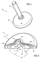
- a support foot for heavy bodies according to an embodiment of the present invention, globally denoted with 100, comprises a stem 105 and a base 110.
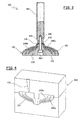
- the stem 105 in the example herein considered, comprises a generally cylindrical steel stem, preferably but not limitatively of stainless steel, or galvanized steel and, on one end thereof intended for the coupling to the base 110, it is provided with a threaded hole 305 (as visible in Figure 3).
- the stem 205 On another, opposite end (not shown in the drawings), intended for the coupling to the body to be supported, the stem 205 may for example be provided with an outer thread, for the coupling by screwing to the body to be supported, so as to allow the height regulation of the foot 100.
- the base 110 comprises an outer supporting cap 115, that is intended to withstand a substantial portion (merely by way of example, approximately the 50% or more) of the total load offered to the base 110 by the body to be supported and transmitted by the stem 105.
- the outer cap 115 has a shape of a generically spherical cap (but other shapes are nevertheless possible, the present invention not being limited to the specific shape of the outer cap 115), and it is made of a material having mechanic characteristics, in particular stiffness, such as to guarantee that the outer cap 115 can support, remaining substantially within the limit of elastic deformability, and thus without plastically deforming o even breaking, said significative portion of the total load.
- the outer cap is made of steel, more preferably stainless steel or nickel-plated steel, for better resisting to the aggression of agents which can be present in the environments where the support foot 100 is intended to be employed.
- the outer cap 115 is for example obtained starting from a generically plane steel sheet of a suitable thickness, for example 3mm, by moulding with drawing and cutting mould. Substantially on its end, in the outer cap 115 a hole 205 is formed, useful for the coupling to the stem 105, as it is better described in the following.
- a mass 210 of a suitable synthetic material is overmoulded onto the outer cap 115, for example nitrilic - NBR - or polyurethanic rubber, having suitable stiffness properties, for resisting without excessively expanding to the loads that the support foot is intended to support (for example, a stiffness of approximately 70-100 ShA).
- the mass 210 substantially fills the concavity of the outer cap 115.
- An exposed surface 215 of the mass 210 forms an anti-slip contact surface of the foot 100 on the support surface.
- the mass 210 protrudes partially from the top hole 205 of the outer cap 115, and forms a spigot 220 projecting from the side of the convexity of the outer cap 115.
- a through hole 225 is provided, centrally, in the mass 210, having a widened portion 230 toward the surface 215 of the mass 210, which forms a shoulder 235.
- the base 110 further includes a core, a reinforcement frame 240, immersed, buried within the synthetic material mass 210;
- the reinforcement support core is made of a material having mechanical properties comparable to these of the material of which the outer cap 115 is formed, so that the reinforcement core can guarantee to support, remaining substantially within the limit of elastic deformability, and thus, in particular, without plastically deforming or breaking, a second significative portion (for example, approximately the remaining 50%) of the overall load, which, together with the first portion, forms substantially the totality of the load, which in the use, the support foot is intended to support.
- the reinforcement core is made of a material with stiffness comparable to that of the material of which the outer cap is made, of hardness greater than that of the synthetic material constituting the mass 210.
- the reinforcement frame 240 comprises at least one, two in the example herein considered, and, more generally, a plurality of inner caps 240a and 240b, for example generically spherical, coaxial and with a diameter progressively reduced compared to the diameter of the outer cap 115.
- the first inner cap 240a can have a diameter of approximately 100mm
- the second inner cap 240b can have diameter of approximately 80mm.
- the support frame 220 and thus, in the example herein considered, the caps 240a and 240b, are made of steel. Being the caps 240a and 240b inner, immersed into the synthetic material mass 210, they have no exposed surfaces, and thus they are not subjected, in the use, to the attack the agents present in the using room of the foot, nor have they to satisfy particular aesthetic requirements, differently from the outer cap 115. Thanks to this, the inner caps 240a and 240b can be made of a material, which, although resistant, is less noble than that used for making the outer cap 115.
- caps 240a and 240b are made of steel, it is possible use simple carbon steel, not necessarily stainless; in other words, since the choice of the material to be used for the frame 240 is not bound by considerations about the resistance to the aggressive agents present in the environment or by aesthetical properties, it is possible to use a material which, from the viewpoint of the strength, even though less noble, is more performant than that which is used for the outer cap 115.
- the caps 240a and 240b used for making the support frame 240 of the base 110 can be caps intended for being used as outer caps 115 for bases of smaller size.
- a screw 310 can be used, which is inserted into the hole 225 from the bottom of the base 110.
- the end of the stem 105 provided with the threaded hole 305 is put onto the spigot 220 of the synthetic material 210 by interposing a slightly convex washer 315.
- the screw 310 is screwed into the hole 305 of the stem; by tightening the screw 310, its head abuts the shoulder 235. In such a way, the support foot 100 is ready for being mounted to the body, which it is intended to support.
- the washer 315 acting as a meniscus, the total load that in the use is transmitted by the stem 105 is transmitted on the outer load-support cap.
- the load is transmitted to the synthetic material mass 210, which partially transmits it directly to the ground or the support surface, and partially transmits it to the caps 240a and 240b, which form the reinforcement frame; particularly, the fraction of the load that is not directly transmitted to the ground is transmitted to the inner cap 240a; from here, the fraction of the load supported by the inner cap 240a is partially transmitted to the ground or the support surface, through the synthetic material mass 210, and partially transmitted, from the synthetic material mass 210, to the other inner cap 240b; finally, the load that weighs down on the latter is transmitted to the ground or the support surface, by the synthetic material mass 210.
- the outer cap actually supports only a first fraction of the total load, albeit significative, a significative second fraction of such load being supported by the reinforcement framework; the first and the second fractions of the load form altogether essentially the totality or however a prevalent portion of the total load which is offered to the support foot.
- the outer cap 115 could comprise a recess for accommodating the end of the stem, instead of the hole 205, with a central hole for the insertion of the screw.
- the transmission of the load from the stem 105 to the inner caps occurs not only by means of the outer cap 115 and the synthetic material mass 210, but also directly by the outer cap 115 in a non-negligible way, since, in correspondence of the hole 205, an edge strip of the inner cap 240a contacts the outer cap 115, and an edge strip of the inner cap 240b contacts in turn the inner cap 240a.
- the outer cap 115 and the inner caps 240a and 240b can be advantageously obtained by moulding with drawing and shearing machine starting from one sheet or sheets of a suitable material, for example metal, particularly steel.
- the inner caps 240a and 240b are placed one within the other, and within of the outer cap 115, and they are all posed in a mould for injection moulding of synthetic material, schematically represented in Figure 4 and denoted therein with 405.
- the mould is closed and synthetic material is made to flow therein, through a feed tube 410.
- the synthetic material fills all the openings between the inner caps 240a and 240b and the outer cap 115, by substantially burying the inner caps 240a and 240b within the hardened synthetic material mass 210.
- the present invention it is possible to produce a particularly strong base for support foot, adapted to support very heavy bodies, such as working machines.
- the improved strength of the support foot is obtained by the reinforcement frame 220, which constitutes a real reinforcement structure buried within the synthetic material mass 210.
- the base for support foot according to the present invention guarantees an axial compression resistance higher than that obtainable without providing the reinforcement core, and which is comparable to that which is obtainable by using solutions much more expensive, such as the machine-tool manufacturing of solid steel bars or the forging, which would imply a great waste of material, great weight of the base and thus scarce handling, and like.
- a base (110) for a support foot (100) for supporting heavy bodies on a support surface comprising: a cap (115) being made of a first material, a synthetic material mass (210) and a contact surface (215) said cap having a concavity on the side that faces the contact surface (215), the synthetic material mass (210) arranged in adhesion to the cap and adapted to substantially fill the concavity of the cap, having a reinforcement frame (240) made of a second material, integrated within said synthetic material mass.
- the method of manufacturing consists of the the steps:
Landscapes
- Engineering & Computer Science (AREA)
- General Engineering & Computer Science (AREA)
- Mechanical Engineering (AREA)
- Orthopedics, Nursing, And Contraception (AREA)
- Photoreceptors In Electrophotography (AREA)
- Supports For Pipes And Cables (AREA)
- Road Signs Or Road Markings (AREA)
- Immobilizing And Processing Of Enzymes And Microorganisms (AREA)
- Materials For Medical Uses (AREA)
- Prostheses (AREA)
- Details Of Measuring And Other Instruments (AREA)
Applications Claiming Priority (1)
| Application Number | Priority Date | Filing Date | Title |
|---|---|---|---|
| IT000393A ITMI20060393A1 (it) | 2006-03-06 | 2006-03-06 | Zoccolo per piede di appoggio ad elevata rsistenza per supportare corpi pesanti |
Publications (3)
| Publication Number | Publication Date |
|---|---|
| EP1832800A2 true EP1832800A2 (de) | 2007-09-12 |
| EP1832800A3 EP1832800A3 (de) | 2009-05-27 |
| EP1832800B1 EP1832800B1 (de) | 2011-05-04 |
Family
ID=38178925
Family Applications (1)
| Application Number | Title | Priority Date | Filing Date |
|---|---|---|---|
| EP07103644A Not-in-force EP1832800B1 (de) | 2006-03-06 | 2007-03-06 | Hochfester Sockel für einen Trägerfuß zum Tragen von schweren Aufbauten |
Country Status (6)
| Country | Link |
|---|---|
| US (1) | US7784753B2 (de) |
| EP (1) | EP1832800B1 (de) |
| AT (1) | ATE508315T1 (de) |
| DE (1) | DE602007014282D1 (de) |
| DK (1) | DK1832800T3 (de) |
| IT (1) | ITMI20060393A1 (de) |
Families Citing this family (6)
| Publication number | Priority date | Publication date | Assignee | Title |
|---|---|---|---|---|
| US8317169B1 (en) * | 2009-09-21 | 2012-11-27 | Christopher Ralph Cantolino | Vibration isolator |
| US8321995B2 (en) | 2011-04-07 | 2012-12-04 | The Display Connection | Pallet glide with staple and screw support regions |
| US20140373887A1 (en) * | 2013-06-25 | 2014-12-25 | Dms Holdings, Inc. | Helix cane stopper |
| US9681714B1 (en) * | 2016-11-11 | 2017-06-20 | Superior Mechanical Solutions Corp. | Automatic direction-correcting apparatus for a cane |
| US9937091B1 (en) * | 2017-06-26 | 2018-04-10 | Ko-Po Chen | Bed supporting device |
| WO2022137905A1 (ja) * | 2020-12-24 | 2022-06-30 | 村田機械株式会社 | 支持部材 |
Family Cites Families (15)
| Publication number | Priority date | Publication date | Assignee | Title |
|---|---|---|---|---|
| USRE18647E (en) * | 1929-07-22 | 1932-11-08 | Leveling cushion eor radio cabinets | |
| US3601345A (en) * | 1968-06-13 | 1971-08-24 | Kenneth W Johnson | Adjustable vibration isolater |
| IN145684B (de) * | 1975-07-01 | 1979-04-21 | Spie Batignolles | |
| DE9012855U1 (de) * | 1990-09-10 | 1990-12-13 | Wolfgang Bänfer Kunststofftechnik, 3590 Bad Wildungen | Vorrichtung zur Abstützung von Maschinen o.dgl. |
| US5794912A (en) * | 1997-02-20 | 1998-08-18 | Unisorb, Inc. | Constant horizontal natural frequency vibration isolation mount pad insert |
| DE29710195U1 (de) * | 1997-06-11 | 1997-08-14 | Wolfgang Bänfer Kunststofftechnik, 34537 Bad Wildungen | Fuß zur Abstützung eines Gegenstands, insbesondere einer sanitären Wanne |
| IT245225Y1 (it) * | 1998-03-19 | 2002-03-20 | Bett Sistemi Srl | Piede di appoggio registrabile. |
| FR2801833B1 (fr) * | 1999-12-03 | 2003-05-16 | Rollin Sa | Un manchon comprenant une couche de solidarisation sur un cylindre support metallique |
| EP1113212A1 (de) * | 1999-12-30 | 2001-07-04 | Rexnord Marbett S.p.A. | Stützfuss für schwere Körper |
| EP1113213A1 (de) * | 1999-12-30 | 2001-07-04 | Rexnord Marbett S.p.A. | Stützfuss für schwere Körper |
| DE10033226A1 (de) * | 2000-07-07 | 2002-01-17 | Ganter Otto Gmbh & Co Kg Normteilefabrik | Beweglicher Maschinenfuß mit Dichtfunktion |
| US6910666B2 (en) * | 2001-10-12 | 2005-06-28 | William J. Burr | Adjustable leveling mount |
| US6938872B2 (en) * | 2003-01-14 | 2005-09-06 | Ngi Aps | Machine shoe for the support of machines and a method |
| US20060289709A1 (en) * | 2003-10-01 | 2006-12-28 | Keitaro Yonezawa | Positioning device and clamping system having the same |
| DE202004006661U1 (de) * | 2004-04-27 | 2004-07-01 | Müller, Luxmee | Maschinenfuß und zugehöriges Verbindungselement |
-
2006
- 2006-03-06 IT IT000393A patent/ITMI20060393A1/it unknown
-
2007
- 2007-03-06 EP EP07103644A patent/EP1832800B1/de not_active Not-in-force
- 2007-03-06 AT AT07103644T patent/ATE508315T1/de not_active IP Right Cessation
- 2007-03-06 DE DE602007014282T patent/DE602007014282D1/de active Active
- 2007-03-06 DK DK07103644.6T patent/DK1832800T3/da active
- 2007-03-06 US US11/682,388 patent/US7784753B2/en active Active
Non-Patent Citations (1)
| Title |
|---|
| None |
Also Published As
| Publication number | Publication date |
|---|---|
| US20070205343A1 (en) | 2007-09-06 |
| DE602007014282D1 (de) | 2011-06-16 |
| EP1832800A3 (de) | 2009-05-27 |
| DK1832800T3 (da) | 2011-09-05 |
| EP1832800B1 (de) | 2011-05-04 |
| ATE508315T1 (de) | 2011-05-15 |
| US7784753B2 (en) | 2010-08-31 |
| ITMI20060393A1 (it) | 2007-09-07 |
Similar Documents
| Publication | Publication Date | Title |
|---|---|---|
| EP1832800B1 (de) | Hochfester Sockel für einen Trägerfuß zum Tragen von schweren Aufbauten | |
| EP2425192B1 (de) | Verankerungsmittel | |
| CA2862070C (en) | Punch rivet and method for the attachment of individual components to one another of which at least one component is formed by a workpiece of composite material | |
| CN101605953B (zh) | 用于处理建筑构件、特别是混凝土板的锚固器 | |
| JP2012506012A (ja) | カラー付きの多角形駆動手段 | |
| EP1213497A1 (de) | Schraube mit Halte-und Dichtteil | |
| US20030204926A1 (en) | Operating handle for cleaning device | |
| CA2231130A1 (en) | Composite socket with double inserts | |
| US20150063902A1 (en) | Mounting unit and method for its production | |
| WO2005119394A3 (en) | Non-homogenous engine component formed by powder metallurgy | |
| CN102562724A (zh) | 用于fkv部件的传力元件 | |
| JP2004524493A (ja) | 作用トルクを制限するためのねじ付ナット及びそれに対応する方法 | |
| EP1840023A1 (de) | Fahrrad-Pedaltretkurbelanordnung and verbundene Teile | |
| CN103511825B (zh) | 车架用衬套套管及其成型方法 | |
| WO2012141850A1 (en) | Combined metal cover and anti-crush hole support | |
| FI58820B (fi) | Anordning foer saekring av en lagerkropp i en baerplatta | |
| KR20170124975A (ko) | 캡형 휠 패스너 및 조립 방법 | |
| CN211333781U (zh) | 用于成型预留孔的模具 | |
| JP4457977B2 (ja) | 化粧栓 | |
| CN218640676U (zh) | 一种环形橡胶支架 | |
| JP3738564B2 (ja) | 耐回転トルク用インサート部材を有する成形体 | |
| JP3001317U (ja) | 鍛造・圧造用組み工具 | |
| KR101080149B1 (ko) | 체결너트 및 그 제조방법 | |
| JP3775979B2 (ja) | 木やせ対応座金付ナット | |
| KR960007820Y1 (ko) | 산업용 플랜지커플링 |
Legal Events
| Date | Code | Title | Description |
|---|---|---|---|
| PUAI | Public reference made under article 153(3) epc to a published international application that has entered the european phase |
Free format text: ORIGINAL CODE: 0009012 |
|
| AK | Designated contracting states |
Kind code of ref document: A2 Designated state(s): AT BE BG CH CY CZ DE DK EE ES FI FR GB GR HU IE IS IT LI LT LU LV MC MT NL PL PT RO SE SI SK TR |
|
| AX | Request for extension of the european patent |
Extension state: AL BA HR MK YU |
|
| PUAL | Search report despatched |
Free format text: ORIGINAL CODE: 0009013 |
|
| AK | Designated contracting states |
Kind code of ref document: A3 Designated state(s): AT BE BG CH CY CZ DE DK EE ES FI FR GB GR HU IE IS IT LI LT LU LV MC MT NL PL PT RO SE SI SK TR |
|
| AX | Request for extension of the european patent |
Extension state: AL BA HR MK RS |
|
| 17P | Request for examination filed |
Effective date: 20090930 |
|
| 17Q | First examination report despatched |
Effective date: 20091102 |
|
| AKX | Designation fees paid |
Designated state(s): AT BE BG CH CY CZ DE DK EE ES FI FR GB GR HU IE IS IT LI LT LU LV MC MT NL PL PT RO SE SI SK TR |
|
| GRAP | Despatch of communication of intention to grant a patent |
Free format text: ORIGINAL CODE: EPIDOSNIGR1 |
|
| GRAS | Grant fee paid |
Free format text: ORIGINAL CODE: EPIDOSNIGR3 |
|
| GRAA | (expected) grant |
Free format text: ORIGINAL CODE: 0009210 |
|
| AK | Designated contracting states |
Kind code of ref document: B1 Designated state(s): AT BE BG CH CY CZ DE DK EE ES FI FR GB GR HU IE IS IT LI LT LU LV MC MT NL PL PT RO SE SI SK TR |
|
| REG | Reference to a national code |
Ref country code: GB Ref legal event code: FG4D |
|
| REG | Reference to a national code |
Ref country code: CH Ref legal event code: EP |
|
| REG | Reference to a national code |
Ref country code: IE Ref legal event code: FG4D |
|
| REF | Corresponds to: |
Ref document number: 602007014282 Country of ref document: DE Date of ref document: 20110616 Kind code of ref document: P |
|
| REG | Reference to a national code |
Ref country code: DE Ref legal event code: R096 Ref document number: 602007014282 Country of ref document: DE Effective date: 20110616 |
|
| REG | Reference to a national code |
Ref country code: SE Ref legal event code: TRGR |
|
| REG | Reference to a national code |
Ref country code: NL Ref legal event code: T3 |
|
| REG | Reference to a national code |
Ref country code: DK Ref legal event code: T3 |
|
| PG25 | Lapsed in a contracting state [announced via postgrant information from national office to epo] |
Ref country code: LT Free format text: LAPSE BECAUSE OF FAILURE TO SUBMIT A TRANSLATION OF THE DESCRIPTION OR TO PAY THE FEE WITHIN THE PRESCRIBED TIME-LIMIT Effective date: 20110504 Ref country code: PT Free format text: LAPSE BECAUSE OF FAILURE TO SUBMIT A TRANSLATION OF THE DESCRIPTION OR TO PAY THE FEE WITHIN THE PRESCRIBED TIME-LIMIT Effective date: 20110905 |
|
| PG25 | Lapsed in a contracting state [announced via postgrant information from national office to epo] |
Ref country code: LV Free format text: LAPSE BECAUSE OF FAILURE TO SUBMIT A TRANSLATION OF THE DESCRIPTION OR TO PAY THE FEE WITHIN THE PRESCRIBED TIME-LIMIT Effective date: 20110504 Ref country code: AT Free format text: LAPSE BECAUSE OF FAILURE TO SUBMIT A TRANSLATION OF THE DESCRIPTION OR TO PAY THE FEE WITHIN THE PRESCRIBED TIME-LIMIT Effective date: 20110504 Ref country code: IS Free format text: LAPSE BECAUSE OF FAILURE TO SUBMIT A TRANSLATION OF THE DESCRIPTION OR TO PAY THE FEE WITHIN THE PRESCRIBED TIME-LIMIT Effective date: 20110904 Ref country code: ES Free format text: LAPSE BECAUSE OF FAILURE TO SUBMIT A TRANSLATION OF THE DESCRIPTION OR TO PAY THE FEE WITHIN THE PRESCRIBED TIME-LIMIT Effective date: 20110815 Ref country code: BE Free format text: LAPSE BECAUSE OF FAILURE TO SUBMIT A TRANSLATION OF THE DESCRIPTION OR TO PAY THE FEE WITHIN THE PRESCRIBED TIME-LIMIT Effective date: 20110504 Ref country code: SI Free format text: LAPSE BECAUSE OF FAILURE TO SUBMIT A TRANSLATION OF THE DESCRIPTION OR TO PAY THE FEE WITHIN THE PRESCRIBED TIME-LIMIT Effective date: 20110504 Ref country code: CY Free format text: LAPSE BECAUSE OF FAILURE TO SUBMIT A TRANSLATION OF THE DESCRIPTION OR TO PAY THE FEE WITHIN THE PRESCRIBED TIME-LIMIT Effective date: 20110504 Ref country code: FI Free format text: LAPSE BECAUSE OF FAILURE TO SUBMIT A TRANSLATION OF THE DESCRIPTION OR TO PAY THE FEE WITHIN THE PRESCRIBED TIME-LIMIT Effective date: 20110504 Ref country code: GR Free format text: LAPSE BECAUSE OF FAILURE TO SUBMIT A TRANSLATION OF THE DESCRIPTION OR TO PAY THE FEE WITHIN THE PRESCRIBED TIME-LIMIT Effective date: 20110805 |
|
| PG25 | Lapsed in a contracting state [announced via postgrant information from national office to epo] |
Ref country code: EE Free format text: LAPSE BECAUSE OF FAILURE TO SUBMIT A TRANSLATION OF THE DESCRIPTION OR TO PAY THE FEE WITHIN THE PRESCRIBED TIME-LIMIT Effective date: 20110504 Ref country code: CZ Free format text: LAPSE BECAUSE OF FAILURE TO SUBMIT A TRANSLATION OF THE DESCRIPTION OR TO PAY THE FEE WITHIN THE PRESCRIBED TIME-LIMIT Effective date: 20110504 |
|
| PG25 | Lapsed in a contracting state [announced via postgrant information from national office to epo] |
Ref country code: PL Free format text: LAPSE BECAUSE OF FAILURE TO SUBMIT A TRANSLATION OF THE DESCRIPTION OR TO PAY THE FEE WITHIN THE PRESCRIBED TIME-LIMIT Effective date: 20110504 Ref country code: RO Free format text: LAPSE BECAUSE OF FAILURE TO SUBMIT A TRANSLATION OF THE DESCRIPTION OR TO PAY THE FEE WITHIN THE PRESCRIBED TIME-LIMIT Effective date: 20110504 Ref country code: SK Free format text: LAPSE BECAUSE OF FAILURE TO SUBMIT A TRANSLATION OF THE DESCRIPTION OR TO PAY THE FEE WITHIN THE PRESCRIBED TIME-LIMIT Effective date: 20110504 |
|
| PLBE | No opposition filed within time limit |
Free format text: ORIGINAL CODE: 0009261 |
|
| STAA | Information on the status of an ep patent application or granted ep patent |
Free format text: STATUS: NO OPPOSITION FILED WITHIN TIME LIMIT |
|
| 26N | No opposition filed |
Effective date: 20120207 |
|
| REG | Reference to a national code |
Ref country code: DE Ref legal event code: R097 Ref document number: 602007014282 Country of ref document: DE Effective date: 20120207 |
|
| PG25 | Lapsed in a contracting state [announced via postgrant information from national office to epo] |
Ref country code: MC Free format text: LAPSE BECAUSE OF NON-PAYMENT OF DUE FEES Effective date: 20120331 |
|
| REG | Reference to a national code |
Ref country code: CH Ref legal event code: PL |
|
| REG | Reference to a national code |
Ref country code: FR Ref legal event code: ST Effective date: 20121130 |
|
| REG | Reference to a national code |
Ref country code: IE Ref legal event code: MM4A |
|
| PG25 | Lapsed in a contracting state [announced via postgrant information from national office to epo] |
Ref country code: IE Free format text: LAPSE BECAUSE OF NON-PAYMENT OF DUE FEES Effective date: 20120306 Ref country code: LI Free format text: LAPSE BECAUSE OF NON-PAYMENT OF DUE FEES Effective date: 20120331 Ref country code: FR Free format text: LAPSE BECAUSE OF NON-PAYMENT OF DUE FEES Effective date: 20120402 Ref country code: CH Free format text: LAPSE BECAUSE OF NON-PAYMENT OF DUE FEES Effective date: 20120331 |
|
| PG25 | Lapsed in a contracting state [announced via postgrant information from national office to epo] |
Ref country code: BG Free format text: LAPSE BECAUSE OF FAILURE TO SUBMIT A TRANSLATION OF THE DESCRIPTION OR TO PAY THE FEE WITHIN THE PRESCRIBED TIME-LIMIT Effective date: 20110804 |
|
| PG25 | Lapsed in a contracting state [announced via postgrant information from national office to epo] |
Ref country code: MT Free format text: LAPSE BECAUSE OF FAILURE TO SUBMIT A TRANSLATION OF THE DESCRIPTION OR TO PAY THE FEE WITHIN THE PRESCRIBED TIME-LIMIT Effective date: 20110504 |
|
| PG25 | Lapsed in a contracting state [announced via postgrant information from national office to epo] |
Ref country code: TR Free format text: LAPSE BECAUSE OF FAILURE TO SUBMIT A TRANSLATION OF THE DESCRIPTION OR TO PAY THE FEE WITHIN THE PRESCRIBED TIME-LIMIT Effective date: 20110504 |
|
| PG25 | Lapsed in a contracting state [announced via postgrant information from national office to epo] |
Ref country code: LU Free format text: LAPSE BECAUSE OF NON-PAYMENT OF DUE FEES Effective date: 20120306 |
|
| PG25 | Lapsed in a contracting state [announced via postgrant information from national office to epo] |
Ref country code: HU Free format text: LAPSE BECAUSE OF FAILURE TO SUBMIT A TRANSLATION OF THE DESCRIPTION OR TO PAY THE FEE WITHIN THE PRESCRIBED TIME-LIMIT Effective date: 20070306 |
|
| PGFP | Annual fee paid to national office [announced via postgrant information from national office to epo] |
Ref country code: NL Payment date: 20150227 Year of fee payment: 9 Ref country code: DE Payment date: 20150320 Year of fee payment: 9 Ref country code: IT Payment date: 20150323 Year of fee payment: 9 Ref country code: DK Payment date: 20150319 Year of fee payment: 9 |
|
| PGFP | Annual fee paid to national office [announced via postgrant information from national office to epo] |
Ref country code: SE Payment date: 20150319 Year of fee payment: 9 Ref country code: GB Payment date: 20150319 Year of fee payment: 9 |
|
| REG | Reference to a national code |
Ref country code: DE Ref legal event code: R119 Ref document number: 602007014282 Country of ref document: DE |
|
| REG | Reference to a national code |
Ref country code: DK Ref legal event code: EBP Effective date: 20160331 |
|
| REG | Reference to a national code |
Ref country code: SE Ref legal event code: EUG |
|
| REG | Reference to a national code |
Ref country code: NL Ref legal event code: MM Effective date: 20160401 |
|
| GBPC | Gb: european patent ceased through non-payment of renewal fee |
Effective date: 20160306 |
|
| PG25 | Lapsed in a contracting state [announced via postgrant information from national office to epo] |
Ref country code: SE Free format text: LAPSE BECAUSE OF NON-PAYMENT OF DUE FEES Effective date: 20160307 |
|
| PG25 | Lapsed in a contracting state [announced via postgrant information from national office to epo] |
Ref country code: DE Free format text: LAPSE BECAUSE OF NON-PAYMENT OF DUE FEES Effective date: 20161001 Ref country code: NL Free format text: LAPSE BECAUSE OF NON-PAYMENT OF DUE FEES Effective date: 20160401 Ref country code: GB Free format text: LAPSE BECAUSE OF NON-PAYMENT OF DUE FEES Effective date: 20160306 |
|
| PG25 | Lapsed in a contracting state [announced via postgrant information from national office to epo] |
Ref country code: IT Free format text: LAPSE BECAUSE OF NON-PAYMENT OF DUE FEES Effective date: 20160306 |
|
| PG25 | Lapsed in a contracting state [announced via postgrant information from national office to epo] |
Ref country code: DK Free format text: LAPSE BECAUSE OF NON-PAYMENT OF DUE FEES Effective date: 20160331 |
|
| P01 | Opt-out of the competence of the unified patent court (upc) registered |
Effective date: 20230522 |