EP1831652B1 - Kapazitiver füllstandssensor und verfahren zur füllstandsschätzung - Google Patents
Kapazitiver füllstandssensor und verfahren zur füllstandsschätzung Download PDFInfo
- Publication number
- EP1831652B1 EP1831652B1 EP05821694.6A EP05821694A EP1831652B1 EP 1831652 B1 EP1831652 B1 EP 1831652B1 EP 05821694 A EP05821694 A EP 05821694A EP 1831652 B1 EP1831652 B1 EP 1831652B1
- Authority
- EP
- European Patent Office
- Prior art keywords
- capacitor
- measurement
- capacitors
- sensor
- tank
- Prior art date
- Legal status (The legal status is an assumption and is not a legal conclusion. Google has not performed a legal analysis and makes no representation as to the accuracy of the status listed.)
- Not-in-force
Links
Images


Classifications
-
- G—PHYSICS
- G01—MEASURING; TESTING
- G01F—MEASURING VOLUME, VOLUME FLOW, MASS FLOW OR LIQUID LEVEL; METERING BY VOLUME
- G01F23/00—Indicating or measuring liquid level or level of fluent solid material, e.g. indicating in terms of volume or indicating by means of an alarm
- G01F23/22—Indicating or measuring liquid level or level of fluent solid material, e.g. indicating in terms of volume or indicating by means of an alarm by measuring physical variables, other than linear dimensions, pressure or weight, dependent on the level to be measured, e.g. by difference of heat transfer of steam or water
- G01F23/26—Indicating or measuring liquid level or level of fluent solid material, e.g. indicating in terms of volume or indicating by means of an alarm by measuring physical variables, other than linear dimensions, pressure or weight, dependent on the level to be measured, e.g. by difference of heat transfer of steam or water by measuring variations of capacity or inductance of capacitors or inductors arising from the presence of liquid or fluent solid material in the electric or electromagnetic fields
- G01F23/263—Indicating or measuring liquid level or level of fluent solid material, e.g. indicating in terms of volume or indicating by means of an alarm by measuring physical variables, other than linear dimensions, pressure or weight, dependent on the level to be measured, e.g. by difference of heat transfer of steam or water by measuring variations of capacity or inductance of capacitors or inductors arising from the presence of liquid or fluent solid material in the electric or electromagnetic fields by measuring variations in capacitance of capacitors
- G01F23/266—Indicating or measuring liquid level or level of fluent solid material, e.g. indicating in terms of volume or indicating by means of an alarm by measuring physical variables, other than linear dimensions, pressure or weight, dependent on the level to be measured, e.g. by difference of heat transfer of steam or water by measuring variations of capacity or inductance of capacitors or inductors arising from the presence of liquid or fluent solid material in the electric or electromagnetic fields by measuring variations in capacitance of capacitors measuring circuits therefor
Definitions
- the invention relates to a capacitive sensor of a liquid level of a reservoir, including a measuring capacitor, intended to be arranged in the reservoir; a reference capacitor, intended to be disposed in the reservoir in a lower part thereof; a standard capacitor with a capacitance greater than that of the measuring capacitor; control means capable of providing a signal for estimating the level of the liquid; an operational amplifier; an integration capacitor connected between the inverting input of the amplifier and its output; and a comparator for comparing the output voltage of the amplifier with a threshold voltage and providing a comparison signal to the control means.
- the invention also relates to a method for estimating the level of a liquid in a tank by capacitive measurement, and the use of such a level capacitive sensor for a tank of a vehicle.
- the French patent application FR 2 795 816 A1 discloses such a sensor.
- This application discloses a level sensor of a liquid in a tank, comprising a measuring capacitor intended to be placed over the entire height of the tank and adapted so that its capacity varies with the level of liquid in the tank and a reference capacitor to be disposed at the bottom of the tank.
- the capacitors are connected to an electronic interpretation circuit, comprising a microcontroller incorporating software means for periodically inducting, in discrete quantities, an integrator from a capacitance to be measured, and then discharging it.
- integrator from a standard capacitance placed in the circuit higher standard capacity than all the capacities to be measured.
- a comparator makes it possible to compare the amount of load of the integrator with a threshold value, and allows the transmission, as soon as the threshold value is exceeded, of a signal to the microcontroller, which entails the collection of a quantity of integrator electricity by the standard capacity, so that the average load of the integrator remains almost constant. The number of times the comparator is at "1" during a given period makes it possible to estimate the level of the liquid in the tank.
- An object of the invention is to overcome the problems of the state of the art and in particular to make it possible to obtain more precise measurements, particularly for applications in which the measurement capacitor and the reference capacitor have value capacities. very different.
- the senor according to the invention is characterized in that it further includes a complementary standard capacitor, with a capacity greater than that of the reference capacitor and different from that of the standard capacitor; in that the control means are intended to implement the following steps, over successive accumulation periods and for a given target capacitor and discharge capacitor at each period: a first step of charging the target capacitor by application of a voltage given at its terminals; a second step of transferring the charge from the target capacitor to the integration capacitor; a third decision step of passing a fourth step if the comparison signal is negative; the fourth step of discharging a portion of the charge of the integrating capacitor into the discharge capacitor and then completely discharging the discharge capacitor; and a fifth step back to the first step; and in that the target and discharge capacitors given at each period are respectively taken from a group of pairs of capacitors, including the measurement capacitor and the standard capacitor, and the reference capacitor and the complementary standard capacitor.
- the charge stored in the sensor integration capacitor according to the invention varies as the successive steps implemented by the control means, so that this charge reaches a given number of times a given charge value corresponding to an output voltage greater than or equal to the threshold voltage, and corresponding to a positive comparison signal.
- This number is substantially proportional to the ratio between the average capacitance of the target capacitor over the given accumulation period and the capacitance of the discharge capacitor, of known value and substantially constant. This number thus enables the control means to estimate the average capacitance of the target capacitor over the given accumulation period.
- the target capacitor may be the measuring capacitor for a number of successive accumulation periods, and then for a subsequent accumulation period the reference capacitor.
- the discharge capacitor of the sensor according to the invention unlike the sensors of the state of the art, it is not indifferently the same standard capacitor that the target capacitor is the measuring capacitor or that it is the capacitor of reference.
- the target and discharge capacitors given at each accumulation period are respectively taken from a group of pairs of capacitors, including the measurement capacitor and the standard capacitor, and the reference capacitor and the complementary standard capacitor.
- the standard capacitor is used as a discharge capacitor
- the complementary standard capacitor is used as the discharge capacitor.
- this association with the target capacitor of a specific discharge capacitor that is to say the association with the measuring capacitor of the standard capacitor and the association with the reference capacitor of the complementary standard capacitor, makes it possible to obtain more accurate estimates.
- the standard capacitor has a capacitance greater than that of the measuring capacitor and the complementary standard capacitor has a capacitance greater than that of the reference capacitor but different from that of the standard capacitor.
- the capacitance of the complementary standard capacitor is, for example, less than or much less than the capacitance value of the standard capacitor.
- the combination of a given target capacitor with a specific discharge capacitor makes it possible, irrespective of the pair in question, to obtain, over a given accumulation period, a sufficiently large thresholding rate per loading, and this is observed in this case. reports of finer capacitance values and increased measurement accuracy.
- the threshold exceedance rate is the ratio of the number of threshold exceedances to the total number of loads for a given accumulation period, which is substantially equal to the ratio of the value of the target capacity to the value of the capacity of the discharge.
- the sensor according to the invention has an additional advantage in that it allows greater freedom in the choice of types of measurement and reference capacitors during the design of the sensor itself. Calibration of the measurements adapted to the value to be measured makes it possible to obtain a better precision in the results, and a greater freedom in the design.
- Another object of the invention is to reduce the parasitic effects of temperature variations due to the materials of the capacitor support.
- the senor according to the invention further includes a first compensation capacitor, the characteristics of which change depending on the temperature substantially in the same way as the materials of the support of the measuring capacitors and reference; and wherein the group of capacitor pairs further includes the first compensation capacitor and the complementary standard capacitor.
- control means can incorporate a consideration of these variations to provide the estimation signal.
- the first compensation capacitor by its composition and its shape, is intended to mimic the evolution of the influence of the dielectric components of the support materials of the measurement and reference capacitors, to compensate for this influence.
- the objective is the use of a more refined model of reality, leading to more accurate estimates, but adding to the system an unknown, the dielectric constant of the support materials, and the solution proposed by the invention is to add to the system an equation, derived from the mathematical expression of the capacitance of the first compensation capacitor, which is a function of the dielectric constant of the materials of the support.
- the sensor according to the invention and the steps implemented by the control means during successive accumulation periods are such that the addition of a capacity of a capacitor to measure adds very little complexity to the sensor and the implementation of its control means, thanks to the flexible nature of the sensor design.
- the international application WO 01/79789 A2 discloses a level measurement system, comprising a measuring circuit that can be used in combination with a capacitive probe to measure the level of a material in a tank.
- the capacitive probe includes a probe capacitance and a reference capacitance used to calibrate the particular material used.
- This circuit comprises a current source and switches for supplying a constant current to the measurement capacitor in order to keep the voltage across the reference capacitor at the same level as the voltage across the measurement capacitor. This eliminates parasitic capacitances by canceling the voltage difference across the conductors between which this parasitic capacitance is likely to appear.
- the level sensor according to the invention operates differently, according to one of these embodiments, by adding a first compensation capacitor, which, in a certain way and as explained above, mimics the variations due to the support for them. integrate into the calculation. This allows the design of a relatively simple sensor architecture. Control and calibration operations are also reduced.
- Another object of the invention is to reduce the parasitic effects of temperature variations due to the materials of the protective layers of the capacitors.
- the senor according to the invention further includes a second compensation capacitor, the characteristics of which change depending on the temperature substantially in the same way respectively as the materials of the protective layers of the capacitors of the capacitors. measurement and reference; and wherein the group of capacitor pairs further includes the second compensation capacitor and the complementary standard capacitor.
- This particular embodiment of the invention allows the compensation of the parasitic capacitance due to the materials of the protective layers and especially the compensation and the taking into account of the effects of the variation thereof as a function of the temperature.
- the probe is a printed circuit with nested comb tracks on which are added an insulating layer, for example varnish, to avoid short circuits.
- control means can be found by detailing the equivalent circuits of the different capacitors, as illustrated and explained later by way of example only, and integrating the solutions of the resulting equations into the equations. Control measures.
- the invention also relates to a sensor in which the first compensation capacitor and the second compensation capacitor are combined, to improve the accuracy by taking into account the influence of both the support materials and the protective layers.
- the invention also relates to a method for estimating the level of a liquid in a tank by capacitive measurement, including the implementation of the following steps, over successive accumulation periods and for a given target capacitor and discharge capacitor.
- a first step of charging the target capacitor by applying a given voltage across its terminals a second step of transferring the charge of the target capacitor to an integrating capacitor (18), connected between the inverting input of an operational amplifier and its output; a third decision step of passing a fourth step if a comparison signal is negative, the comparison signal being provided by a comparator, for comparing the output voltage of the amplifier to a threshold voltage; the fourth step of discharging a portion of the charge of the integrating capacitor into the discharge capacitor and then completely discharging the discharge capacitor; and a fifth step back to the first step; the target and discharge capacitors given at each period being respectively taken from a group of pairs of capacitors, including a measurement capacitor, intended to be arranged in the tank, and a standard capacitor, with a capacitance greater than that of the measurement
- This method makes it possible to estimate more precisely the level of liquid in the tank, while allowing inexpensive and flexible implementations.
- the invention also relates to the use of a sensor as described above, in a tank of a vehicle, for example a fuel tank of an automobile.
- the sensor according to the invention is particularly well suited to the field of application where cost and precision constraints are very important.
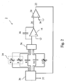
- the Fig. 1 shows a schematic view of a particular embodiment of the sensor according to the invention.
- the measuring capacitor 4, intended to be arranged in the tank 24, and shown therein, is connected at its terminals to the control means 26.
- the reference capacitor 6, intended to be disposed in a lower part of the tank 24 , and necessary to compensate for the variations of the dielectric constant of the liquid, is also connected at its terminals to the control means 26.
- the standard capacitor 8 and the complementary standard capacitor 10 are arranged outside or inside the tank 24, by example on an electronic circuit, which may be called “electronic circuit interpretation", and are connected at their respective terminals to the control means 26.
- the capacitance value of the measuring capacitor 4 varies mainly as a function of the level of the liquid in the tank 24, that is to say of its level of filling, and also as a function of the dielectric constant of the liquid in question.
- the capacitance value of the reference capacitor 6 varies mainly according to the dielectric constant of the liquid in question.
- the reference capacitor 6 is preferably intended to be immersed permanently in the liquid.
- the values of the standard capacitor 8 and the complementary standard capacitor 10 are not intended to vary according to the level 44 of the liquid or its dielectric constant. These latter values are intended to remain generally constant regardless of the level 44 or temperature changes in the tank 24.
- the operational amplifier 16 is connected in its inverting terminal to the control means 26 and its non-inverting terminal to a given voltage in operation, for example to ground. It provides an output voltage 28.
- the integration capacitor 18 is connected between the non-inverting terminal and the output of the operational amplifier 16.
- the output voltage 28 or output signal is supplied to the non-inverting terminal of the comparator 20.
- a threshold voltage 30 is applied to the inverting terminal of the comparator 20 so that the comparison signal 22 is positive, or equal to 1 for example, if the output voltage 28 is greater than the threshold voltage 30 and negative, or equal to 0 for example, otherwise.
- the comparison signal 22 is supplied to the control means 26, which supplies to their turn an estimation signal 32 of the level 44 of the liquid in the tank 24.
- the senor 2 In operation, and by reference to both the Fig. 1 and at the Fig. 4 , the sensor 2 according to a particular embodiment of the invention operates in the following manner. Periods of accumulation follow one another. Note that these could of course bear other names, such as estimation periods or measurement periods of a capacity without departing from the spirit of the invention. Each period aims to estimate the capacitance value of a variable capacitor, that is to say, according to a particular embodiment, either the measuring capacitor 4 or the reference capacitor 6.
- a number p of accumulation periods associated with the measurement capacitor 4 can advantageously succeed each other before an accumulation period associated with the reference capacitor 6 occurs, after which the cycle can resume.
- This mode of operation is adapted to cases where the level 44 of the liquid in the tank 24 varies faster than its dielectric properties.
- a so-called target capacitor either the measuring capacitor 4 or the reference capacitor 6
- a so-called discharge capacitor respectively the standard capacitor 8 or the complementary standard capacitor 10.
- the pairs, or pairs of capacitors are specific and adapted from the point of view of the value of the capacities to be measured, which makes it possible to obtain a more accurate estimate. precise level 44 liquid.
- a separate standard capacitor 8 and a complementary standard capacitor 10 are indeed chosen because of the significant difference between the ranges of the expected values of the capacitance of the measurement capacitor 4 and the expected values of the capacitance of the reference capacitor 6.
- the control means 26 are clocked and implement the following steps.
- the target capacitor 4, 6 is, in a first step 34, electrically charged by application to its terminals of a determined voltage.
- the charge of the target capacitor is transferred to the integration capacitor 18. This can for example be implemented by a system of switches with switched capacitors.
- the comparison signal 22 is examined by the control means 26. If it is positive, a fourth step 40 is implemented, consisting of partially discharging the integration capacitor 18 in the and through the capacitor discharge 8, 10 and then completely discharge the discharge capacitor 8, 10.
- the first step 34 and the following are then implemented again in order, this return to the first step 34 constituting the fifth step 42. If the comparison signal 22 is negative, the first step 34 and the following are directly implemented again; in other words, the fourth step 40 is passed and the fifth step 42, back, is directly implemented.
- the number of threshold n threshold exceeded is substantially equal to the ratio of the value of the capacitance of the target target capacitor C to the value of the capacitance of the discharging capacitor C discharge , the whole multiplied by the total charging number n of the integration capacitor 18.
- n threshold VS measured , empty VS standard , 8 ⁇ not total
- the factor k represents the factor taking into account the variations of the properties of the dielectrics of the measurement capacitor 4 (variations due to the composition of the liquid, for example a fuel, or temperature), that is to say mainly the variations of the dielectric constant of the liquid whose level 44 is measured, compensated by the estimation of the capacitance of the reference capacitor 6.
- h not threshold , reference , empty not threshold , measured , empty ⁇ not threshold , measured - not threshold , measured , empty not threshold , reference - not threshold , reference , empty where the numbers of "empty" threshold exceedances are estimated before the filling of the tank 24, then stored by the control means 26 for example.
- the control means 26 may, for example, be implemented with switches with switched capacitors, with non-overlapping clocks, to avoid possible short circuits or other undesirable effects.
- the control means 26 manage and implement in particular both the level estimation calculations and the load transfers during a period of accumulation.
- the measurement capacitors 4 and measurement capacitors 6 may for example be physically pairs of flat plates parallel, coaxial tubes or combs nested on planar substrate or circuit board.
- the capacitor of integration 18 may or may not be discharged in the interval between the two accumulation periods.
- the estimation signal 32 may be used, for example, to indicate or display the level 44 of the liquid in the reservoir 24 or to control directly or indirectly a solenoid valve for filling the reservoir 24 or any other actuator, for example in order to ensure safety, especially if the tank 24 is intended to be a fuel tank 24 of a vehicle.
- the influence of other dielectrics is taken into account to provide the estimation signal 32.
- These other dielectrics can in particular be specific to the architecture of the sensor portion 2 intended to be in contact with the liquid in the tank 24, that is to say, specific to the relative arrangement of the measurement capacitors 4 and reference 6 and their physical design.
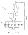
- the Fig. 2 shows a schematic view of a particular embodiment of the sensor 2 according to the invention, in which the influence of other dielectrics is taken into account by the control means 26 to provide the estimation signal 32. More precisely, it is the influence of the variations as a function of the temperature of the dielectric constant of the materials of the support of the measurement capacitors 4 and reference 6 which is taken into account.
- the spacers and other support elements making it possible to keep the parallel plates at a substantially constant distance of each other, in the case of an implementation by coaxial tubes, the support elements separating the two coaxial electrodes and, in the case of an implementation by nested combs placed on a dielectric substrate, the substrate itself. even.
- a first compensation capacitor 12 is presented on the Fig. 2 . It is disposed in the environment of the reservoir 24, that is to say in it or close to it, or in similar or identical environmental conditions, and is connected at its terminals to the Control means 26.
- the properties of the dielectric of the first compensation capacitor 12 evolve as a function of temperature, and possibly other factors, substantially in the same manner as the materials of the capacitor support. measurement 4 and reference 6, so as to mimic their evolution and to allow their taking into account and their compensation by the control means 26 to provide the estimation signal 32.
- the value of the capacitance of the first compensation capacitor 12 is estimated periodically during a given accumulation period by association with a discharge capacitor, for example the complementary standard capacitor 10. This value is used by the control means 26 for provide the estimation signal 32.
- the dielectric constant of the insulator forming the support which is for example a thermosetting resin reinforced or not, or a thermoplastic resin.
- the dielectric constant of such a material indeed varies in particular with the temperature and could, without this compensation, taint an estimate.
- the Fig. 3 shows a schematic view of a particular embodiment of the sensor 2 according to the invention, in which the influence of the variations as a function of the temperature of the dielectric constant of the support materials and the materials of the protective layers of the measurement capacitors 4 and reference 6 is taken into account.
- protective layer is meant, for example, a polymer-based or varnish-based insulation, which can be advantageously used for various reasons, or any another layer obtained in particular by surface treatment of the conductor, for example by controlled oxidation.
- a polymer-based or varnish-based insulation which can be advantageously used for various reasons, or any another layer obtained in particular by surface treatment of the conductor, for example by controlled oxidation.
- One reason may be in particular to avoid the effects of the capillarity of the liquid on the electrodes, this capillarity can indeed lead to estimation errors by modifying (either in more or less) in contact with the surface the actual height of the level of the liquid in the tank, especially in the case of implementation of capacitor of the comb type nested on plane substrate.
- another reason may be to avoid short circuits between the electrodes of the capacitor, during the insertion between them electrically conductive impurities.
- This protective layer degrades the accuracy of the measurement and its consideration improves accuracy.
- the estimation of the level 44 of the liquid can be done by adding to the sensor 2 any number of additional compensation capacitors, so as to take into account other parasitic capacitances, corresponding for example to the number of different media in the The environment of the physical part of the sensor 2.
- the influence of the electrical connections can for example also be the subject of such compensation.
- the control means 26 are able to provide on this basis an estimation signal 32 compensated for the reasons and in the manner explained below.
- the capacitance of a capacitor formed by two conductors to the potentials A and B and by n dielectrics is by decomposition into subdomains in each of which the permittivity of the dielectric is uniform (for example domains consisting of a single dielectric),
- This general formulation can sometimes be simplified when the geometry of the capacitor formed by the drivers meets certain conditions.
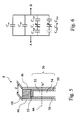
- the Fig. 5 shows a measurement capacitor 4 used according to a particular embodiment of the sensor 2 according to the invention and the Fig. 6 shows an example of an equivalent circuit of the measuring capacitor 4 of the Fig. 5 .
- This equivalent circuit can be used to design or / and program the control means 26 according to the invention.
- the measurement capacitor 4 is represented schematically and schematically on the Fig. 5 just like its model circuit or equivalent circuit on the Fig. 6 .
- the Fig. 5 and 6 are presented in more detail in the following.
- the Fig. 5 shows the two electrodes 46 of the measuring capacitor 4. They are separated by a distance d.
- a substrate or support material is disposed in an area 48, said area of the support material 48. This area covers an area S m (in section) and the filling material has a relative permittivity epsilon m .
- a protective layer is disposed in the zone 50, said zone of the protective layer 50. This zone covers an area S cp and the material filling it has a relative permittivity epsilon cp .
- the zone 56 said zone of variable capacity 56, has a variable capacity with the level 44 of the liquid and a shared area S u in operation between gas and liquid depending on the level 44 of the liquid.
- the variable capacity area 56 is separated into two parts: on the one hand, the zone 54 bathed by the liquid, of area S u ⁇ H where H is the relative height, and relative permittivity epsilon r and, secondly, the area 52 bathed by gas or air, of area S u ⁇ 1 - H and of relative permittivity substantially equal to 1.
- the capacitance of the measurement capacitor 4 that is to say the capacitance between the electrodes 46 represented on the Fig. 5 or the capacitance between terminals A and B on the equivalent circuit of the Fig. 6 , can be calculated by breaking down the capacitor and its four-part capacitance, corresponding to four parallel capacitances, of value:
- VS 12 epsilon 0 ⁇ epsilon m ⁇ S m d + epsilon cp ⁇ S cp d + S u ⁇ 1 - H ⁇ 2 ⁇ e epsilon cp + d - 2 ⁇ e - 1 + S u ⁇ H ⁇ 2 ⁇ e epsilon cp + d - 2 ⁇ e epsilon r - 1
- the relation which relates the relative height H of liquid to the value C 12 of the capacitance of the measurement capacitor 4 depends on the state of the liquid via epsilon r , as well as two other parameters epsilon m and epsilon cp resulting from the practical realization. of the sensor 2 via the materials used.
- the first compensation capacitor 12 is produced and adjoins the environment of the measurement capacitor 4 and the reference capacitor 6.
- This first compensation capacitor 12 thanks to the properties of its dielectric and thanks to its shape, imitates, possibly via a proportionality factor or an association function pre-established by prior measurement, the evolution as a function of the temperature, for example of the capacitance C 1 , and it simulates the capacitors with the same thicknesses and identical materials from identical fabrications.
- the measured capacity value at the terminals of the first compensation capacitor 12 is worth substantially VS 1 ' ⁇ epsilon 0 ⁇ epsilon m ⁇ S m d
- the value of the capacitance measured at the terminals of the second compensation capacitor 14 is substantially equal to VS 2 ' ⁇ epsilon 0 ⁇ epsilon cp ⁇ S cp d
- VS 120 epsilon 0 ⁇ epsilon m ⁇ S m d + epsilon cp ⁇ S cp d + S u ⁇ 2 ⁇ e epsilon cp + d - 2 ⁇ e - 1
- VS 110 epsilon 0 ⁇ epsilon m ⁇ S mr d + epsilon cp ⁇ S cpr d + S ur ⁇ 2 ⁇ e epsilon cp + d - 2 ⁇ e - 1
- VS 12 - VS 120 epsilon 0 ⁇ S u ⁇ H 2 ⁇ e epsilon cp + d - 2 ⁇ e e
- the senor 2 includes an electronic circuit disposed in the upper part of the sensor 2, so as to implement in particular the control means 26, and further includes a tracking track. conducting connection of the reference capacitor 6 to the electronic circuit.
- the influence of the parasitic capacitance generated by the presence of the connecting track is taken into account for the estimation of the level 44 of the liquid.
- connection track is materialized by a track or a cable arranged along the measurement capacitor 4, and which extends over the entire height of this capacitor and allows the transmission of the measurement of the capacitance of the reference capacitor 6 to the circuit .
- the connection track acts as an additional capacity which is added to the capacity of the reference capacitor 6. This parasitic capacitance varies according to the level 44 of the liquid since the track is disposed in the zone 56 of variable capacity.
- This sensor 2 makes it possible to improve the accuracy of the estimation of the level 44 of the liquid.
- the influence of the dielectrics or certain dielectrics structure is not compensated by the addition of compensation capacitors, but is taken into account by a prior calibration.
- the standard capacitor 8 acting as a discharge capacitor during an accumulation period and associated with a target capacitor whose value is a priori not known. is previously selected automatically, based on an initial measurement of the dielectric constant of the liquid, through the reference capacitor 6. This improves the accuracy of the measurement of the capacitance value of the target capacitor, for example measuring capacitor 4.
- the reference capacitor 6 is used to measure the level 44 of the liquid on the same height thereof.
- the reference capacitor 6 is conventionally intended to measure the dielectric constant variations of the liquid present in the tank 24 as a function of the temperature and the composition of the liquid. The very presence of this reference capacitor 6 prevents measuring the level 44 of liquid when this level is very low. However, it is possible to obtain a liquid level value 44, albeit with less precision, keeping in mind memory the value of the vacuum capacity during the first filling of the tank 24.
- the control means 26 operate differently when filling the tank 24 and during the descent of the liquid in the tank 24.
- the evolution of the level 44 of the liquid is much slower during the descent of the level 44 than when filling the tank 24.
- An adaptation of the succession of periods of accumulation and their duration depending on the type of process examined, a descent or rise of the level 44 of the liquid, can advantageously be integrated and implemented in the control means 26.
- the control means 26 are made in electronic form and the corresponding electronic part is disposed inside the tank 24, in the liquid or vapor phase, immediately near the reinforcements. This reduces the parasitic capacitances due to the length of the connections between the armatures and the electronic circuit, to reduce the influence of the temperature, to produce a single circuit board, in the case an implementation using printed circuits for the realization of the control means 26 and the measurement capacitors 4 and 6 in the reservoir 24, and simplify the manufacture while reducing costs.
- the senor 2 according to the invention can be used for example for a tank 24 of a vehicle, for example an automobile, and that the liquid can for example be fuel, including diesel, gasoline or liquefied petroleum gas.
- the expression "disposed in the tank 24" means both in the tank 24, but also at the edge of the tank 24 to the extent that the capacitance of the capacitors whose arrangement is concerned is influenced by significantly and measurably by the dielectric changes inside the tank 24.
- the expression "disposed in a lower part of the tank 24" means disposed sufficiently low in the latter so as to be able to generally provide a non-level dependent reference measurement 44, except possibly due to the effects of connection, and in operation. always always immersed, preferably.
- the reference capacitor 6 may also be for example disposed in the discharge pipe of the tank 24.
- the expression "of capacity greater than that of the measuring capacitor 4" means greater than the capacitance value of the measuring capacitor 4 under normal conditions of use, ie when the liquid has for example a dielectric constant of between 1 and 80 or about 80.
- control means 26 may in particular be electrical, electronic or computer means, made for example in the form of one or more electronic circuits or one or more microprocessors.
- the estimation signal 32 of the liquid level 44 can be either analog or digital without departing from the principle of the invention. If the control means 26 are in the form of an electronic circuit and the latter is disposed in the tank 24, an analogue signal that is not very sensitive to external disturbances or a digital signal is preferred according to an embodiment of the invention. invention for transmitting the tank estimation signal.
- the operational amplifier 16 and the comparator 20 may be arbitrary, regardless of their performance, their quality, their input and output impedance or their ideality.
- Load transfers can for example be implemented by a system of switched capacitors, non-overlapping cycles, to avoid possible short circuits and other inconveniences as explained above.
- the duration of accumulation periods may for example be 600 milliseconds. In general, the longer the period, the more accurate the measurement. Nevertheless, as it is often necessary to obtain a measure sufficiently regularly, to limit to a certain extent the duration of accumulation periods is unavoidable.
- the duration of the transient period before going into power and of charging the integration capacitor 18 from a zero value to the threshold voltage 20 may vary depending on the capacitance of the target capacitor and depending on the capacitance of the integration capacitor 18. This duration may for example be from 50 to 200 microseconds.
- the threshold voltage 30 can for example be 2.5 volts.
- an alert signal is provided, such that for example the presence of an undesirable liquid, such as water in the tank 24 can be communicated to the control systems of the vehicle.
Claims (11)
- Kapazitiver Geber (2) für den Füllstand (44) einer Flüssigkeit in einem Behälter (24), der Folgendes aufweist:einen Messkondensator (4), der dazu bestimmt ist, in dem Behälter (24) angeordnet zu werden;einen Referenzkondensator (6), der dazu bestimmt ist, in dem Behälter (24) in einem unteren Teil davon angeordnet zu werden;einen Normalkondensator (8) mit einer Kapazität, die höher ist als diejenige des Messkondensators (4);Steuermittel (26), die geeignet sind, ein Schätzsignal (32) des Füllstands (44) der Flüssigkeit zu liefern;einen Operationsverstärker (16);einen Integrationskondensator (18), der zwischen dem invertierenden Eingang des Verstärkers (16) und seinem Ausgang geschaltet ist; undeinen Komparator (20), der dazu bestimmt ist, die Ausgangsspannung (28) des Verstärkers (16) mit einer Schwellenspannung (30) zu vergleichen und ein Vergleichssignal (22) an die Steuermittel (26) zu liefern;dadurch gekennzeichnet, dass:er ferner einen ergänzenden Normalkondensator (10) aufweist, dessen Kapazität höher ist als diejenige des Referenzkondensators (6) und sich von derjenigen des Normalkondensators (8) unterscheidet; und dadurch, dass:die Steuermittel (26) dazu bestimmt sind, auf aufeinanderfolgenden Akkumulierungsperioden und für einen gegebenen Zielkondensator und einen gegebenen Entladungskondensator in jeder Periode die folgenden Schritte durchzuführen:einen ersten Schritt (34) des Ladens des Zielkondensators durch Anlegen einer gegebenen Spannung an seine Anschlüsse;einen zweiten Schritt (36) des Transfers der Ladung des Zielkondensators zu dem Integrationskondensator (18);einen dritten Schritt (38) der Entscheidung, die im Überspringen eines vierten Schrittes (40) besteht, wenn das Vergleichssignal (22) negativ ist;den vierten Schritt (40) des Entladens eines Teils der Ladung des Integrationskondensators (18) in den Entladungskondensator und des anschließenden vollständigen Entladens des Entladungskondensators; undeinen fünften Schritt (42) der Rückkehr zum ersten Schritt (34); und dadurch, dass:die gegebenen Ziel- und Entladungskondensatoren in jeder Periode jeweils aus einer Gruppe von Kondensatorpaaren ausgewählt sind, aufweisend:den Messkondensator (4) und den Normalkondensator (8), undden Referenzkondensator (6) und den ergänzenden Normalkondensator (10).
- Geber (2) nach Anspruch 1, wobei der ergänzende Normalkondensator (10) eine Kapazität aufweist, die niedriger ist als diejenige des Normalkondensators (8).
- Geber (2) nach Anspruch 1 oder 2,
der ferner einen ersten Kompensationskondensator (12), dessen Eigenschaften sich in Abhängigkeit von der Temperatur im Wesentlichen auf dieselbe Weise verändern wie Trägermaterialien des Mess- (4) und des Referenzkondensators (6); und
wobei die Gruppe von Kondensatorpaaren ferner aufweist:den ersten Kompensationskondensator (12) und einen zugehörigen ersten Entladungskondensator. - Geber (2) nach Anspruch 3, wobei der erste zugehörige Entladungskondensator der ergänzende Normalkondensator (10) ist.
- Geber (2) nach einem der vorhergehenden Ansprüche,
der ferner einen zweiten Kompensationskompensator (14) aufweist, dessen Eigenschaften sich in Abhängigkeit von der Temperatur im Wesentlichen auf dieselbe Weise verändern wie Materialien der Schutzschichten des Mess- (4) beziehungsweise Referenzkondensators (6);
und wobei die Gruppe von Kondensatorpaaren ferner aufweist:den zweiten Kompensationskondensator (12) und einen zugehörigen zweiten Entladungskondensator. - Geber (2) nach Anspruch 5, wobei der zugehörige zweite Entladungskondensator der ergänzende Normalkondensator (10) ist.
- Geber (2) nach einem der vorhergehenden Ansprüche, wobei die Steuermittel dazu bestimmt sind, den Normalkondensator (8) automatisch unter verschiedenen Kondensatoren vor der Akkumulierungsperiode, die dem Messkondensator (4) zugeordnet ist, in Abhängigkeit von einer Anfangsmessung der Dielektrizitätskonstante der Flüssigkeit auszuwählen, die auf dem Referenzkondensator (6) durchgeführt wurde.
- Geber (2) nach einem der vorhergehenden Ansprüche, wobei die Steuermittel (26) in der Form einer elektronischen Schaltung ausgeführt sind, die im Inneren des Behälters (24) angeordnet ist.
- Verfahren zum Schätzen des Füllstands (44) einer Flüssigkeit in einem Behälter (24) durch kapazitive Messung, das die Durchführung der folgenden Schritte auf aufeinanderfolgenden Akkumulierungsperioden und für einen gegebenen Zielkondensator und einen gegebenen Entladungskondensator bei jedem Schritt umfasst:einen ersten Schritt (34) des Ladens des Zielkondensators durch Anlegen einer gegebenen Spannung an seine Anschlussklemmen;einen zweiten Schritt (36) des Transfers der Ladung des Zielkondensators zu einem Integrationskondensators (18), der zwischen dem invertierenden Eingang eines Operationsverstärkers (16) und seinem Ausgang geschaltet ist;einen dritten Schritt (38) des Entscheidens, der darin besteht, einen vierten Schritt (40) zu überspringen, wenn ein Vergleichssignal (22) negativ ist, wobei das Vergleichssignal (22) durch einen Komparator (20) geliefert wird, der dazu bestimmt ist, die Ausgangsspannung (28) des Verstärkers (16) mit einer Schwellenspannung (22) zu vergleichen;den vierten Schritt (40) des Entladens eines Teils der Ladung des Integrationskondensators (18) in den Entladungskondensator und des anschließenden vollständigen Entladens des Entladungskondensators; undeinen fünften Schritt (42) der Rückkehr zum ersten Schritt (34);wobei der gegebene Zielkondensator und der gegebene Entladungskondensator in jeder Periode jeweils das einer Gruppe von Kondensatorpaaren ausgewählt sind, aufweisend:einen Messkondensator (4), der dazu bestimmt ist, in dem Behälter (24) angeordnet zu werden, und einen Normalkondensator (8), dessen Kapazität höher ist als diejenige des Messkondensators (4), undeinen Referenzkondensator (6), der dazu bestimmt ist, in dem Behälter (24) in einem unteren Teil davon angeordnet zu werden, und den ergänzenden Normalkondensator (10), dessen Kapazität höher ist als diejenige des Referenzkondensators (6) und sich von derjenigen des Normalkondensators (8) unterscheidet.
- Verfahren nach Anspruch 9, wobei ein Alarmsignal geliefert wird, wenn ein atypischer Füllstand (44) geschätzt wird.
- Verwendung eines Gebers (2) nach einem der Ansprüche 1 bis 8 in einem Behälter (24).
Priority Applications (1)
| Application Number | Priority Date | Filing Date | Title |
|---|---|---|---|
| EP05821694.6A EP1831652B1 (de) | 2004-12-22 | 2005-12-20 | Kapazitiver füllstandssensor und verfahren zur füllstandsschätzung |
Applications Claiming Priority (3)
| Application Number | Priority Date | Filing Date | Title |
|---|---|---|---|
| EP04106868A EP1677084A1 (de) | 2004-12-22 | 2004-12-22 | Flüssigkeitspegelsensor und Verfahren zur Schätzung |
| EP05821694.6A EP1831652B1 (de) | 2004-12-22 | 2005-12-20 | Kapazitiver füllstandssensor und verfahren zur füllstandsschätzung |
| PCT/EP2005/056968 WO2006067149A2 (fr) | 2004-12-22 | 2005-12-20 | Capteur capacitif de niveau d'un liquide et methode d'estimation du niveau |
Publications (2)
| Publication Number | Publication Date |
|---|---|
| EP1831652A2 EP1831652A2 (de) | 2007-09-12 |
| EP1831652B1 true EP1831652B1 (de) | 2013-06-05 |
Family
ID=34930124
Family Applications (2)
| Application Number | Title | Priority Date | Filing Date |
|---|---|---|---|
| EP04106868A Pending EP1677084A1 (de) | 2004-12-22 | 2004-12-22 | Flüssigkeitspegelsensor und Verfahren zur Schätzung |
| EP05821694.6A Not-in-force EP1831652B1 (de) | 2004-12-22 | 2005-12-20 | Kapazitiver füllstandssensor und verfahren zur füllstandsschätzung |
Family Applications Before (1)
| Application Number | Title | Priority Date | Filing Date |
|---|---|---|---|
| EP04106868A Pending EP1677084A1 (de) | 2004-12-22 | 2004-12-22 | Flüssigkeitspegelsensor und Verfahren zur Schätzung |
Country Status (7)
| Country | Link |
|---|---|
| US (1) | US7845224B2 (de) |
| EP (2) | EP1677084A1 (de) |
| JP (1) | JP2008524619A (de) |
| KR (1) | KR101264943B1 (de) |
| CN (1) | CN100473954C (de) |
| BR (1) | BRPI0519379A2 (de) |
| WO (1) | WO2006067149A2 (de) |
Families Citing this family (33)
| Publication number | Priority date | Publication date | Assignee | Title |
|---|---|---|---|---|
| KR20080063358A (ko) * | 2005-10-26 | 2008-07-03 | 이너지 오토모티브 시스템즈 리서치 (소시에떼 아노님) | 용량 게이지 |
| FR2892509B1 (fr) | 2005-10-26 | 2007-12-21 | Inergy Automotive Systems Res | Jauge capacitive pour reservoir a carburant |
| US8181516B2 (en) | 2006-10-26 | 2012-05-22 | Inergy Automotive Systems Research (Societe Anonyme) | Measuring a liquid level in a tank with two measurement capacitors and two reference capacitors |
| US8093914B2 (en) * | 2007-12-14 | 2012-01-10 | Cypress Semiconductor Corporation | Compensation circuit for a TX-RX capacitive sensor |
| CA2629960C (en) * | 2008-04-28 | 2009-12-08 | Westport Power Inc. | Apparatus and method for improving the accuracy of measurements taken with a capacitance-type sensor |
| US8237456B2 (en) | 2009-03-02 | 2012-08-07 | Atmel Corporation | Capacitive sensing |
| ATE526559T1 (de) * | 2009-03-10 | 2011-10-15 | Em Microelectronic Marin Sa | Elektronischer schaltkreis mit kapazitivem sensor zur messung eines physikalischen parameters und verfahren zur ingangsetzung des elektronischen schaltkreises |
| US8281655B2 (en) * | 2009-04-03 | 2012-10-09 | Eaton Corporation | Fuel gauging system utilizing a digital fuel gauging probe |
| US8225654B2 (en) * | 2009-07-01 | 2012-07-24 | Tecan Trading Ag | Self-compensating capacitive liquid level detector |
| CH702180B1 (de) * | 2009-11-02 | 2015-02-13 | Tecan Trading Ag | Verfahren zum Testen eines Laborgeräts und entsprechendes Laborgerät. |
| US8604774B2 (en) * | 2010-12-07 | 2013-12-10 | Himax Technologies Limited | Current sensing circuit with feedback control and dual capacitor set range setting |
| DE102010062622A1 (de) * | 2010-12-08 | 2012-06-14 | Ifm Electronic Gmbh | Verfahren zur Selbstüberwachung einer keramischen Druckmesszelle eines kapazitiven Drucksensors und eine Auswerteschaltung zur Durchführung des Verfahrens |
| CN102116663B (zh) * | 2010-12-20 | 2012-05-30 | 皇明太阳能股份有限公司 | 一种渐变式电容传感器 |
| CN103619605B (zh) * | 2011-06-27 | 2015-11-25 | 惠普发展公司,有限责任合伙企业 | 墨水液面传感器和相关方法 |
| KR20130068790A (ko) * | 2011-12-16 | 2013-06-26 | 에이디반도체(주) | 정전용량 방식의 레벨 센서 및 레벨 감지 방법 |
| AT513452B1 (de) * | 2012-10-05 | 2014-08-15 | Ait Austrian Inst Technology | Abgabevorrichtung für Medikamente |
| CN102944286B (zh) * | 2012-11-14 | 2015-06-10 | 北京信息科技大学 | 液位检测电路及检测方法 |
| CN102997974B (zh) * | 2012-12-24 | 2014-12-10 | 电子科技大学 | 一种自适应式电容液位计 |
| US10203238B2 (en) | 2014-03-07 | 2019-02-12 | Barrelogix, Llc | Liquid detection apparatus |
| AU2015241071A1 (en) | 2014-03-31 | 2016-10-27 | University Of Utah Research Foundation | Fluid analysis device and associated systems and methods |
| CN104020358B (zh) * | 2014-06-10 | 2016-09-28 | 济南大学 | 一种测量lng气罐内介质介电常数及液位的方法 |
| CN110567554B (zh) * | 2014-10-08 | 2020-12-08 | 半导体元件工业有限责任公司 | 用于检测填充水平的设备 |
| WO2016068913A1 (en) | 2014-10-29 | 2016-05-06 | Hewlett-Packard Development Company, L.P. | Fluid ejection device with printhead ink level sensor |
| CN106194738A (zh) * | 2015-05-08 | 2016-12-07 | 丹佛斯(天津)有限公司 | 监控装置和监控方法 |
| US10448875B2 (en) | 2015-10-15 | 2019-10-22 | Stream DX, Inc | Capacitive measurement device with integrated electrical and mechanical shielding |
| US10499573B1 (en) | 2016-05-16 | 2019-12-10 | Keith Lynn Paulsen | Wireless soil profile monitoring apparatus and methods |
| US10228340B2 (en) * | 2016-05-16 | 2019-03-12 | Keith Lynn Paulsen | Wireless soil profile monitoring apparatus and methods |
| GB2550402B (en) | 2016-05-19 | 2022-04-20 | Ultra Electronics Ltd | Circuit for simulating a capacitance fuel probe |
| WO2018217818A1 (en) | 2017-05-22 | 2018-11-29 | Stream DX, Inc | Capacitive measurement device with minimized sensitivity to manufacturing variability and environmental changes |
| KR102337627B1 (ko) * | 2018-01-24 | 2021-12-09 | 선전 구딕스 테크놀로지 컴퍼니, 리미티드 | 커패시턴스 검출 회로, 터치 장치와 단말 장치 |
| CN108896131B (zh) * | 2018-05-08 | 2019-11-26 | 鲁东大学 | 射频导纳物位仪中基于温度补偿的物位测量单元及物位仪 |
| CN108645481B (zh) * | 2018-06-22 | 2021-03-16 | 华帝股份有限公司 | 一种非接触式电容液位检测方法 |
| CN112161673B (zh) * | 2020-09-15 | 2022-06-17 | 厦门晶尊微电子科技有限公司 | 一种精准电容式液位检测电路及调整方式 |
Family Cites Families (37)
| Publication number | Priority date | Publication date | Assignee | Title |
|---|---|---|---|---|
| US3801902A (en) * | 1972-07-27 | 1974-04-02 | Gull Airborne Instruments Inc | Electrical measuring apparatus employing a plurality of condition responsive devices |
| CA1070780A (en) * | 1976-06-16 | 1980-01-29 | Canadian General Electric Company Limited | Two wire multiple switching system |
| GB1601338A (en) * | 1977-03-14 | 1981-10-28 | Huddart R | Measuring apparatus using parameter dependant capacitance |
| FR2438827A1 (fr) * | 1978-10-12 | 1980-05-09 | Smiths Industries Ltd | Appareil de jaugeage de fluide |
| FR2447555A1 (fr) | 1979-01-26 | 1980-08-22 | Jaeger | Circuit de mesure de capacite, notamment pour une jauge capacitive de niveau de liquide |
| US4214479A (en) * | 1979-05-21 | 1980-07-29 | Simmonds Precision Products, Inc. | Capacitive type fuel probe compensation circuit |
| GB2058364B (en) | 1979-09-01 | 1983-03-23 | Ferranti Ltd | Capacitance measuring apparatus |
| US4388828A (en) * | 1980-05-14 | 1983-06-21 | Honeywell Inc. | Liquid gaging system sensor calibration |
| US4444051A (en) * | 1981-03-18 | 1984-04-24 | Nissan Motor Company, Limited | Electronic liquid level gauge |
| EP0120852B1 (de) * | 1982-09-30 | 1990-05-23 | The Boeing Company | Brennstoffpeilsystem |
| DE3610166A1 (de) * | 1985-04-03 | 1986-10-09 | Smiths Industries Public Ltd. Co., London | Fuellstandsmessgeraet |
| DE3778094D1 (de) * | 1986-08-01 | 1992-05-14 | Siemens Ag | Verfahren und einrichtung zur erkennung der polaritaet gepolter kondensatoren. |
| US4947689A (en) * | 1989-01-13 | 1990-08-14 | Hochstein Peter A | Capacitive liquid sensor |
| US5451940A (en) * | 1989-12-20 | 1995-09-19 | Endress U. Hauser Gmbh U. Co. | Capacitive sensor signal processing arrangement using switch capacitor structures |
| SU1767451A1 (ru) | 1990-05-03 | 1992-10-07 | Институт Автоматики Ан Киргсср | Измерительный преобразователь с емкостным датчиком |
| US5042299A (en) * | 1990-07-23 | 1991-08-27 | Iimorrow, Inc. | Capacitive fluid level sensor |
| DE4031210A1 (de) * | 1990-10-04 | 1992-04-09 | Bosch Gmbh Robert | Kapazitiver sensor zur messung eines kraftstoffwandfilms |
| DE4237196C1 (de) | 1992-11-04 | 1994-02-10 | Vega Grieshaber Gmbh & Co | Verfahren und Anordnung zur Messung zumindest einer Kapazität |
| US5461321A (en) | 1993-09-17 | 1995-10-24 | Penberthy, Inc. | Apparatus and method for measuring capacitance from the duration of a charge-discharge charge cycle |
| DE4340472C1 (de) | 1993-11-27 | 1995-04-06 | Grieshaber Vega Kg | Verfahren und Schaltungsanordnung zur Messung einer Kapazität |
| US5613398A (en) * | 1994-01-24 | 1997-03-25 | Chrysler Corporation | Smart fuel tank module |
| JP3216955B2 (ja) * | 1994-05-31 | 2001-10-09 | 株式会社日立製作所 | 容量式センサ装置 |
| DE4421906C2 (de) * | 1994-06-24 | 1996-10-24 | Vdo Schindling | Verfahren und Schaltungsanordnung zur Messung des Widerstandes eines Widerstandssensors |
| US5576628A (en) * | 1994-09-30 | 1996-11-19 | Telcom Semiconductor, Inc. | Method and apparatus to measure capacitance |
| US5661240A (en) * | 1995-09-25 | 1997-08-26 | Ford Motor Company | Sampled-data interface circuit for capacitive sensors |
| KR100211114B1 (ko) | 1997-05-27 | 1999-07-15 | 허금자 | 액체 레벨 검출기 |
| EP0931244A1 (de) * | 1997-06-12 | 1999-07-28 | Andrew M. Matulek | Kapazitiver flüssigkeitsstandsanzeiger |
| WO1999010714A1 (en) | 1997-08-25 | 1999-03-04 | Millennium Sensors Ltd. | A compensated capacitive liquid level sensor |
| WO1999067604A1 (en) | 1998-06-24 | 1999-12-29 | Cordant Technologies, Inc. | Monitoring liquid level in a container with a capacitive transducer |
| FR2795816B1 (fr) * | 1999-07-02 | 2001-09-28 | Roxer | Capteur de niveau |
| US6502460B1 (en) * | 2000-01-11 | 2003-01-07 | Delphi Technologies, Inc. | Fluid level measuring system |
| JP3662808B2 (ja) | 2000-04-14 | 2005-06-22 | 理想科学工業株式会社 | 液体検出方法および液体検出装置 |
| EP1274972B1 (de) | 2000-04-14 | 2005-07-06 | Robertshaw Controls Company | Kapazitive pegelmessungsschaltung und -sonde |
| JP2001343273A (ja) | 2000-05-31 | 2001-12-14 | Nippon Parkerizing Co Ltd | 粉体検出用静電容量型センサ |
| US6781388B2 (en) * | 2001-09-26 | 2004-08-24 | Delphi Technologies, Inc. | Liquid property sensor |
| DE102004006020A1 (de) * | 2004-02-06 | 2005-08-25 | E + E Elektronik Ges.M.B.H. | Schaltungsanordnung zur kapazitiven Feuchtemessung und Verfahren zum Betrieb derselben |
| JP4310695B2 (ja) * | 2004-03-30 | 2009-08-12 | アイシン精機株式会社 | 静電容量変化検出装置 |
-
2004
- 2004-12-22 EP EP04106868A patent/EP1677084A1/de active Pending
-
2005
- 2005-12-20 KR KR1020077014366A patent/KR101264943B1/ko not_active IP Right Cessation
- 2005-12-20 EP EP05821694.6A patent/EP1831652B1/de not_active Not-in-force
- 2005-12-20 CN CNB2005800475813A patent/CN100473954C/zh not_active Expired - Fee Related
- 2005-12-20 US US11/793,542 patent/US7845224B2/en not_active Expired - Fee Related
- 2005-12-20 BR BRPI0519379-6A patent/BRPI0519379A2/pt active Search and Examination
- 2005-12-20 WO PCT/EP2005/056968 patent/WO2006067149A2/fr active Application Filing
- 2005-12-20 JP JP2007547491A patent/JP2008524619A/ja active Pending
Also Published As
| Publication number | Publication date |
|---|---|
| CN101128722A (zh) | 2008-02-20 |
| BRPI0519379A2 (pt) | 2009-01-20 |
| EP1831652A2 (de) | 2007-09-12 |
| US20090120159A1 (en) | 2009-05-14 |
| JP2008524619A (ja) | 2008-07-10 |
| WO2006067149A2 (fr) | 2006-06-29 |
| WO2006067149A3 (fr) | 2006-08-24 |
| CN100473954C (zh) | 2009-04-01 |
| EP1677084A1 (de) | 2006-07-05 |
| US7845224B2 (en) | 2010-12-07 |
| KR101264943B1 (ko) | 2013-05-15 |
| KR20070091155A (ko) | 2007-09-07 |
Similar Documents
| Publication | Publication Date | Title |
|---|---|---|
| EP1831652B1 (de) | Kapazitiver füllstandssensor und verfahren zur füllstandsschätzung | |
| EP1831653B1 (de) | Capacitive liquid level sensor | |
| EP1835263B1 (de) | Elektronischer Schnittstellenschaltkreis eines kapazitiven Sensors zur Messung eines physikalischen Parameters und Verfahren zur Ingangsetzung des elektronischen Schaltkreises | |
| EP1784480B1 (de) | Verfahren und vorrichtung zur biomassenbestimmung in einem medium, insbesondere einem biologische zellen enthaltenden medium, sowie messvorrichtung unter verwendung des verfahrens | |
| EP3026430B1 (de) | Bildgebendes verfahren für ein medium basierend auf elektrischen messungen mit korrektur der kontaktimpedanz | |
| EP0612982B1 (de) | Messschaltung für Widerstandssensor, insbesondere Krafstoffmesser | |
| FR3029298A1 (fr) | Procede automatique d'estimation de l'etat de charge d'une cellule d'une batterie | |
| EP0613012A1 (de) | Kapazitiver Beschleunigungsmesser mit Schaltung zur Korrektur des störender Einflusses parasitärer Kapazitäten | |
| FR3090117A1 (fr) | Estimation du soh et estimation du soc d’un element electrochimique | |
| FR2985017A1 (fr) | Dispositif de mesure d'une variation d'une capacite a faible consommation et procede associe | |
| EP2834658A1 (de) | Verfahren und vorrichtung zum messen eines magnetfeldes und der temperatur eines magnetoresistiven wandlers | |
| FR2795816A1 (fr) | Capteur de niveau | |
| EP3737920B1 (de) | Vorrichtung zur kapazitiven messung in einem mehrphasigen medium | |
| EP3414578B1 (de) | Vorrichtung zur messung einer elektrischen menge einer phase eines wechselstroms eines freileitungsstromnetzes | |
| WO2016102823A1 (fr) | Procede d'estimation de grandeurs physiques caracteristiques d'une batterie electrique | |
| EP1336082B1 (de) | Kapazitiver messwertgeber | |
| FR2720510A1 (fr) | Dispositif de mesure d'une force. | |
| FR3045218A1 (fr) | Determination de parametres d'un modele dynamique pour une cellule electrochimique de batterie | |
| FR2898985A1 (fr) | Procede et systeme de determination de l'etat de sante de moyens de stockage d'energie electrique. | |
| FR2654834A1 (fr) | Sonde capacitive pour la mesure in situ de la teneur en eau d'un sol. | |
| FR2817036A1 (fr) | Dispositif de mesure exploitant une mesure indirecte de permettivite a grande dynamique | |
| EP2251773B1 (de) | Verfahren zur Validierung von Koordinatendaten einer resistive Berührungsempfindlichen Oberfläche, und zum Ausschluss von fehlerhaften Koordinatendaten | |
| WO2009112179A1 (fr) | Dispositif de mesure d'une variation de capacite, capteur capacitif mettant en oeuvre un tel dispositif et procede associe | |
| FR3096775A1 (fr) | Dispositif de mesures capacitives d’une hauteur d’un fluide dans un réservoir | |
| FR2987134A1 (fr) | Procede et dispositif de mesure de l'evolution dans le temps des performances electriques d'un transistor fdsoi |
Legal Events
| Date | Code | Title | Description |
|---|---|---|---|
| PUAI | Public reference made under article 153(3) epc to a published international application that has entered the european phase |
Free format text: ORIGINAL CODE: 0009012 |
|
| 17P | Request for examination filed |
Effective date: 20070723 |
|
| AK | Designated contracting states |
Kind code of ref document: A2 Designated state(s): AT BE BG CH CY CZ DE DK EE ES FI FR GB GR HU IE IS IT LI LT LU LV MC NL PL PT RO SE SI SK TR |
|
| RIN1 | Information on inventor provided before grant (corrected) |
Inventor name: BARLESI, LORENZO Inventor name: CHIAFFI, MICHEL Inventor name: NAYDENOV, VOLODIA |
|
| DAX | Request for extension of the european patent (deleted) | ||
| GRAP | Despatch of communication of intention to grant a patent |
Free format text: ORIGINAL CODE: EPIDOSNIGR1 |
|
| GRAS | Grant fee paid |
Free format text: ORIGINAL CODE: EPIDOSNIGR3 |
|
| GRAA | (expected) grant |
Free format text: ORIGINAL CODE: 0009210 |
|
| AK | Designated contracting states |
Kind code of ref document: B1 Designated state(s): AT BE BG CH CY CZ DE DK EE ES FI FR GB GR HU IE IS IT LI LT LU LV MC NL PL PT RO SE SI SK TR |
|
| REG | Reference to a national code |
Ref country code: GB Ref legal event code: FG4D Free format text: NOT ENGLISH |
|
| REG | Reference to a national code |
Ref country code: CH Ref legal event code: EP |
|
| REG | Reference to a national code |
Ref country code: AT Ref legal event code: REF Ref document number: 615921 Country of ref document: AT Kind code of ref document: T Effective date: 20130615 |
|
| REG | Reference to a national code |
Ref country code: IE Ref legal event code: FG4D Free format text: LANGUAGE OF EP DOCUMENT: FRENCH |
|
| REG | Reference to a national code |
Ref country code: DE Ref legal event code: R096 Ref document number: 602005039918 Country of ref document: DE Effective date: 20130801 |
|
| REG | Reference to a national code |
Ref country code: AT Ref legal event code: MK05 Ref document number: 615921 Country of ref document: AT Kind code of ref document: T Effective date: 20130605 |
|
| PG25 | Lapsed in a contracting state [announced via postgrant information from national office to epo] |
Ref country code: ES Free format text: LAPSE BECAUSE OF FAILURE TO SUBMIT A TRANSLATION OF THE DESCRIPTION OR TO PAY THE FEE WITHIN THE PRESCRIBED TIME-LIMIT Effective date: 20130916 Ref country code: AT Free format text: LAPSE BECAUSE OF FAILURE TO SUBMIT A TRANSLATION OF THE DESCRIPTION OR TO PAY THE FEE WITHIN THE PRESCRIBED TIME-LIMIT Effective date: 20130605 Ref country code: LT Free format text: LAPSE BECAUSE OF FAILURE TO SUBMIT A TRANSLATION OF THE DESCRIPTION OR TO PAY THE FEE WITHIN THE PRESCRIBED TIME-LIMIT Effective date: 20130605 Ref country code: FI Free format text: LAPSE BECAUSE OF FAILURE TO SUBMIT A TRANSLATION OF THE DESCRIPTION OR TO PAY THE FEE WITHIN THE PRESCRIBED TIME-LIMIT Effective date: 20130605 Ref country code: SI Free format text: LAPSE BECAUSE OF FAILURE TO SUBMIT A TRANSLATION OF THE DESCRIPTION OR TO PAY THE FEE WITHIN THE PRESCRIBED TIME-LIMIT Effective date: 20130605 Ref country code: GR Free format text: LAPSE BECAUSE OF FAILURE TO SUBMIT A TRANSLATION OF THE DESCRIPTION OR TO PAY THE FEE WITHIN THE PRESCRIBED TIME-LIMIT Effective date: 20130906 Ref country code: SE Free format text: LAPSE BECAUSE OF FAILURE TO SUBMIT A TRANSLATION OF THE DESCRIPTION OR TO PAY THE FEE WITHIN THE PRESCRIBED TIME-LIMIT Effective date: 20130605 |
|
| REG | Reference to a national code |
Ref country code: NL Ref legal event code: VDEP Effective date: 20130605 |
|
| REG | Reference to a national code |
Ref country code: LT Ref legal event code: MG4D |
|
| PG25 | Lapsed in a contracting state [announced via postgrant information from national office to epo] |
Ref country code: BG Free format text: LAPSE BECAUSE OF FAILURE TO SUBMIT A TRANSLATION OF THE DESCRIPTION OR TO PAY THE FEE WITHIN THE PRESCRIBED TIME-LIMIT Effective date: 20130905 Ref country code: PL Free format text: LAPSE BECAUSE OF FAILURE TO SUBMIT A TRANSLATION OF THE DESCRIPTION OR TO PAY THE FEE WITHIN THE PRESCRIBED TIME-LIMIT Effective date: 20130605 |
|
| PG25 | Lapsed in a contracting state [announced via postgrant information from national office to epo] |
Ref country code: LV Free format text: LAPSE BECAUSE OF FAILURE TO SUBMIT A TRANSLATION OF THE DESCRIPTION OR TO PAY THE FEE WITHIN THE PRESCRIBED TIME-LIMIT Effective date: 20130605 |
|
| PG25 | Lapsed in a contracting state [announced via postgrant information from national office to epo] |
Ref country code: PT Free format text: LAPSE BECAUSE OF FAILURE TO SUBMIT A TRANSLATION OF THE DESCRIPTION OR TO PAY THE FEE WITHIN THE PRESCRIBED TIME-LIMIT Effective date: 20131007 Ref country code: EE Free format text: LAPSE BECAUSE OF FAILURE TO SUBMIT A TRANSLATION OF THE DESCRIPTION OR TO PAY THE FEE WITHIN THE PRESCRIBED TIME-LIMIT Effective date: 20130605 Ref country code: SK Free format text: LAPSE BECAUSE OF FAILURE TO SUBMIT A TRANSLATION OF THE DESCRIPTION OR TO PAY THE FEE WITHIN THE PRESCRIBED TIME-LIMIT Effective date: 20130605 Ref country code: CZ Free format text: LAPSE BECAUSE OF FAILURE TO SUBMIT A TRANSLATION OF THE DESCRIPTION OR TO PAY THE FEE WITHIN THE PRESCRIBED TIME-LIMIT Effective date: 20130605 Ref country code: IS Free format text: LAPSE BECAUSE OF FAILURE TO SUBMIT A TRANSLATION OF THE DESCRIPTION OR TO PAY THE FEE WITHIN THE PRESCRIBED TIME-LIMIT Effective date: 20131005 |
|
| PG25 | Lapsed in a contracting state [announced via postgrant information from national office to epo] |
Ref country code: NL Free format text: LAPSE BECAUSE OF FAILURE TO SUBMIT A TRANSLATION OF THE DESCRIPTION OR TO PAY THE FEE WITHIN THE PRESCRIBED TIME-LIMIT Effective date: 20130605 Ref country code: RO Free format text: LAPSE BECAUSE OF FAILURE TO SUBMIT A TRANSLATION OF THE DESCRIPTION OR TO PAY THE FEE WITHIN THE PRESCRIBED TIME-LIMIT Effective date: 20130605 |
|
| PLBE | No opposition filed within time limit |
Free format text: ORIGINAL CODE: 0009261 |
|
| STAA | Information on the status of an ep patent application or granted ep patent |
Free format text: STATUS: NO OPPOSITION FILED WITHIN TIME LIMIT |
|
| PG25 | Lapsed in a contracting state [announced via postgrant information from national office to epo] |
Ref country code: DK Free format text: LAPSE BECAUSE OF FAILURE TO SUBMIT A TRANSLATION OF THE DESCRIPTION OR TO PAY THE FEE WITHIN THE PRESCRIBED TIME-LIMIT Effective date: 20130605 |
|
| 26N | No opposition filed |
Effective date: 20140306 |
|
| PG25 | Lapsed in a contracting state [announced via postgrant information from national office to epo] |
Ref country code: IT Free format text: LAPSE BECAUSE OF FAILURE TO SUBMIT A TRANSLATION OF THE DESCRIPTION OR TO PAY THE FEE WITHIN THE PRESCRIBED TIME-LIMIT Effective date: 20130605 |
|
| REG | Reference to a national code |
Ref country code: DE Ref legal event code: R097 Ref document number: 602005039918 Country of ref document: DE Effective date: 20140306 |
|
| BERE | Be: lapsed |
Owner name: INERGY AUTOMOTIVE SYSTEMS RESEARCH (SOCIETE ANONY Effective date: 20131231 |
|
| REG | Reference to a national code |
Ref country code: CH Ref legal event code: PL |
|
| GBPC | Gb: european patent ceased through non-payment of renewal fee |
Effective date: 20131220 |
|
| PG25 | Lapsed in a contracting state [announced via postgrant information from national office to epo] |
Ref country code: LU Free format text: LAPSE BECAUSE OF FAILURE TO SUBMIT A TRANSLATION OF THE DESCRIPTION OR TO PAY THE FEE WITHIN THE PRESCRIBED TIME-LIMIT Effective date: 20131220 Ref country code: MC Free format text: LAPSE BECAUSE OF FAILURE TO SUBMIT A TRANSLATION OF THE DESCRIPTION OR TO PAY THE FEE WITHIN THE PRESCRIBED TIME-LIMIT Effective date: 20130605 |
|
| REG | Reference to a national code |
Ref country code: IE Ref legal event code: MM4A |
|
| PG25 | Lapsed in a contracting state [announced via postgrant information from national office to epo] |
Ref country code: CH Free format text: LAPSE BECAUSE OF NON-PAYMENT OF DUE FEES Effective date: 20131231 Ref country code: LI Free format text: LAPSE BECAUSE OF NON-PAYMENT OF DUE FEES Effective date: 20131231 Ref country code: IE Free format text: LAPSE BECAUSE OF NON-PAYMENT OF DUE FEES Effective date: 20131220 Ref country code: BE Free format text: LAPSE BECAUSE OF NON-PAYMENT OF DUE FEES Effective date: 20131231 |
|
| PG25 | Lapsed in a contracting state [announced via postgrant information from national office to epo] |
Ref country code: GB Free format text: LAPSE BECAUSE OF NON-PAYMENT OF DUE FEES Effective date: 20131220 |
|
| PG25 | Lapsed in a contracting state [announced via postgrant information from national office to epo] |
Ref country code: TR Free format text: LAPSE BECAUSE OF FAILURE TO SUBMIT A TRANSLATION OF THE DESCRIPTION OR TO PAY THE FEE WITHIN THE PRESCRIBED TIME-LIMIT Effective date: 20130605 Ref country code: CY Free format text: LAPSE BECAUSE OF FAILURE TO SUBMIT A TRANSLATION OF THE DESCRIPTION OR TO PAY THE FEE WITHIN THE PRESCRIBED TIME-LIMIT Effective date: 20130605 |
|
| PG25 | Lapsed in a contracting state [announced via postgrant information from national office to epo] |
Ref country code: HU Free format text: LAPSE BECAUSE OF FAILURE TO SUBMIT A TRANSLATION OF THE DESCRIPTION OR TO PAY THE FEE WITHIN THE PRESCRIBED TIME-LIMIT; INVALID AB INITIO Effective date: 20051220 |
|
| REG | Reference to a national code |
Ref country code: FR Ref legal event code: PLFP Year of fee payment: 11 |
|
| REG | Reference to a national code |
Ref country code: FR Ref legal event code: PLFP Year of fee payment: 12 |
|
| REG | Reference to a national code |
Ref country code: FR Ref legal event code: PLFP Year of fee payment: 13 |
|
| PGFP | Annual fee paid to national office [announced via postgrant information from national office to epo] |
Ref country code: DE Payment date: 20171228 Year of fee payment: 13 |
|
| PGFP | Annual fee paid to national office [announced via postgrant information from national office to epo] |
Ref country code: FR Payment date: 20181220 Year of fee payment: 14 |
|
| REG | Reference to a national code |
Ref country code: DE Ref legal event code: R119 Ref document number: 602005039918 Country of ref document: DE |
|
| PG25 | Lapsed in a contracting state [announced via postgrant information from national office to epo] |
Ref country code: DE Free format text: LAPSE BECAUSE OF NON-PAYMENT OF DUE FEES Effective date: 20190702 |
|
| PG25 | Lapsed in a contracting state [announced via postgrant information from national office to epo] |
Ref country code: FR Free format text: LAPSE BECAUSE OF NON-PAYMENT OF DUE FEES Effective date: 20191231 |