EP1831652B1 - Liquid level sensor and method of estimation - Google Patents
Liquid level sensor and method of estimation Download PDFInfo
- Publication number
- EP1831652B1 EP1831652B1 EP05821694.6A EP05821694A EP1831652B1 EP 1831652 B1 EP1831652 B1 EP 1831652B1 EP 05821694 A EP05821694 A EP 05821694A EP 1831652 B1 EP1831652 B1 EP 1831652B1
- Authority
- EP
- European Patent Office
- Prior art keywords
- capacitor
- measurement
- capacitors
- sensor
- tank
- Prior art date
- Legal status (The legal status is an assumption and is not a legal conclusion. Google has not performed a legal analysis and makes no representation as to the accuracy of the status listed.)
- Not-in-force
Links
Images


Classifications
-
- G—PHYSICS
- G01—MEASURING; TESTING
- G01F—MEASURING VOLUME, VOLUME FLOW, MASS FLOW OR LIQUID LEVEL; METERING BY VOLUME
- G01F23/00—Indicating or measuring liquid level or level of fluent solid material, e.g. indicating in terms of volume or indicating by means of an alarm
- G01F23/22—Indicating or measuring liquid level or level of fluent solid material, e.g. indicating in terms of volume or indicating by means of an alarm by measuring physical variables, other than linear dimensions, pressure or weight, dependent on the level to be measured, e.g. by difference of heat transfer of steam or water
- G01F23/26—Indicating or measuring liquid level or level of fluent solid material, e.g. indicating in terms of volume or indicating by means of an alarm by measuring physical variables, other than linear dimensions, pressure or weight, dependent on the level to be measured, e.g. by difference of heat transfer of steam or water by measuring variations of capacity or inductance of capacitors or inductors arising from the presence of liquid or fluent solid material in the electric or electromagnetic fields
- G01F23/263—Indicating or measuring liquid level or level of fluent solid material, e.g. indicating in terms of volume or indicating by means of an alarm by measuring physical variables, other than linear dimensions, pressure or weight, dependent on the level to be measured, e.g. by difference of heat transfer of steam or water by measuring variations of capacity or inductance of capacitors or inductors arising from the presence of liquid or fluent solid material in the electric or electromagnetic fields by measuring variations in capacitance of capacitors
- G01F23/266—Indicating or measuring liquid level or level of fluent solid material, e.g. indicating in terms of volume or indicating by means of an alarm by measuring physical variables, other than linear dimensions, pressure or weight, dependent on the level to be measured, e.g. by difference of heat transfer of steam or water by measuring variations of capacity or inductance of capacitors or inductors arising from the presence of liquid or fluent solid material in the electric or electromagnetic fields by measuring variations in capacitance of capacitors measuring circuits therefor
Definitions
- the invention relates to a capacitive sensor of a liquid level of a reservoir, including a measuring capacitor, intended to be arranged in the reservoir; a reference capacitor, intended to be disposed in the reservoir in a lower part thereof; a standard capacitor with a capacitance greater than that of the measuring capacitor; control means capable of providing a signal for estimating the level of the liquid; an operational amplifier; an integration capacitor connected between the inverting input of the amplifier and its output; and a comparator for comparing the output voltage of the amplifier with a threshold voltage and providing a comparison signal to the control means.
- the invention also relates to a method for estimating the level of a liquid in a tank by capacitive measurement, and the use of such a level capacitive sensor for a tank of a vehicle.
- the French patent application FR 2 795 816 A1 discloses such a sensor.
- This application discloses a level sensor of a liquid in a tank, comprising a measuring capacitor intended to be placed over the entire height of the tank and adapted so that its capacity varies with the level of liquid in the tank and a reference capacitor to be disposed at the bottom of the tank.
- the capacitors are connected to an electronic interpretation circuit, comprising a microcontroller incorporating software means for periodically inducting, in discrete quantities, an integrator from a capacitance to be measured, and then discharging it.
- integrator from a standard capacitance placed in the circuit higher standard capacity than all the capacities to be measured.
- a comparator makes it possible to compare the amount of load of the integrator with a threshold value, and allows the transmission, as soon as the threshold value is exceeded, of a signal to the microcontroller, which entails the collection of a quantity of integrator electricity by the standard capacity, so that the average load of the integrator remains almost constant. The number of times the comparator is at "1" during a given period makes it possible to estimate the level of the liquid in the tank.
- An object of the invention is to overcome the problems of the state of the art and in particular to make it possible to obtain more precise measurements, particularly for applications in which the measurement capacitor and the reference capacitor have value capacities. very different.
- the senor according to the invention is characterized in that it further includes a complementary standard capacitor, with a capacity greater than that of the reference capacitor and different from that of the standard capacitor; in that the control means are intended to implement the following steps, over successive accumulation periods and for a given target capacitor and discharge capacitor at each period: a first step of charging the target capacitor by application of a voltage given at its terminals; a second step of transferring the charge from the target capacitor to the integration capacitor; a third decision step of passing a fourth step if the comparison signal is negative; the fourth step of discharging a portion of the charge of the integrating capacitor into the discharge capacitor and then completely discharging the discharge capacitor; and a fifth step back to the first step; and in that the target and discharge capacitors given at each period are respectively taken from a group of pairs of capacitors, including the measurement capacitor and the standard capacitor, and the reference capacitor and the complementary standard capacitor.
- the charge stored in the sensor integration capacitor according to the invention varies as the successive steps implemented by the control means, so that this charge reaches a given number of times a given charge value corresponding to an output voltage greater than or equal to the threshold voltage, and corresponding to a positive comparison signal.
- This number is substantially proportional to the ratio between the average capacitance of the target capacitor over the given accumulation period and the capacitance of the discharge capacitor, of known value and substantially constant. This number thus enables the control means to estimate the average capacitance of the target capacitor over the given accumulation period.
- the target capacitor may be the measuring capacitor for a number of successive accumulation periods, and then for a subsequent accumulation period the reference capacitor.
- the discharge capacitor of the sensor according to the invention unlike the sensors of the state of the art, it is not indifferently the same standard capacitor that the target capacitor is the measuring capacitor or that it is the capacitor of reference.
- the target and discharge capacitors given at each accumulation period are respectively taken from a group of pairs of capacitors, including the measurement capacitor and the standard capacitor, and the reference capacitor and the complementary standard capacitor.
- the standard capacitor is used as a discharge capacitor
- the complementary standard capacitor is used as the discharge capacitor.
- this association with the target capacitor of a specific discharge capacitor that is to say the association with the measuring capacitor of the standard capacitor and the association with the reference capacitor of the complementary standard capacitor, makes it possible to obtain more accurate estimates.
- the standard capacitor has a capacitance greater than that of the measuring capacitor and the complementary standard capacitor has a capacitance greater than that of the reference capacitor but different from that of the standard capacitor.
- the capacitance of the complementary standard capacitor is, for example, less than or much less than the capacitance value of the standard capacitor.
- the combination of a given target capacitor with a specific discharge capacitor makes it possible, irrespective of the pair in question, to obtain, over a given accumulation period, a sufficiently large thresholding rate per loading, and this is observed in this case. reports of finer capacitance values and increased measurement accuracy.
- the threshold exceedance rate is the ratio of the number of threshold exceedances to the total number of loads for a given accumulation period, which is substantially equal to the ratio of the value of the target capacity to the value of the capacity of the discharge.
- the sensor according to the invention has an additional advantage in that it allows greater freedom in the choice of types of measurement and reference capacitors during the design of the sensor itself. Calibration of the measurements adapted to the value to be measured makes it possible to obtain a better precision in the results, and a greater freedom in the design.
- Another object of the invention is to reduce the parasitic effects of temperature variations due to the materials of the capacitor support.
- the senor according to the invention further includes a first compensation capacitor, the characteristics of which change depending on the temperature substantially in the same way as the materials of the support of the measuring capacitors and reference; and wherein the group of capacitor pairs further includes the first compensation capacitor and the complementary standard capacitor.
- control means can incorporate a consideration of these variations to provide the estimation signal.
- the first compensation capacitor by its composition and its shape, is intended to mimic the evolution of the influence of the dielectric components of the support materials of the measurement and reference capacitors, to compensate for this influence.
- the objective is the use of a more refined model of reality, leading to more accurate estimates, but adding to the system an unknown, the dielectric constant of the support materials, and the solution proposed by the invention is to add to the system an equation, derived from the mathematical expression of the capacitance of the first compensation capacitor, which is a function of the dielectric constant of the materials of the support.
- the sensor according to the invention and the steps implemented by the control means during successive accumulation periods are such that the addition of a capacity of a capacitor to measure adds very little complexity to the sensor and the implementation of its control means, thanks to the flexible nature of the sensor design.
- the international application WO 01/79789 A2 discloses a level measurement system, comprising a measuring circuit that can be used in combination with a capacitive probe to measure the level of a material in a tank.
- the capacitive probe includes a probe capacitance and a reference capacitance used to calibrate the particular material used.
- This circuit comprises a current source and switches for supplying a constant current to the measurement capacitor in order to keep the voltage across the reference capacitor at the same level as the voltage across the measurement capacitor. This eliminates parasitic capacitances by canceling the voltage difference across the conductors between which this parasitic capacitance is likely to appear.
- the level sensor according to the invention operates differently, according to one of these embodiments, by adding a first compensation capacitor, which, in a certain way and as explained above, mimics the variations due to the support for them. integrate into the calculation. This allows the design of a relatively simple sensor architecture. Control and calibration operations are also reduced.
- Another object of the invention is to reduce the parasitic effects of temperature variations due to the materials of the protective layers of the capacitors.
- the senor according to the invention further includes a second compensation capacitor, the characteristics of which change depending on the temperature substantially in the same way respectively as the materials of the protective layers of the capacitors of the capacitors. measurement and reference; and wherein the group of capacitor pairs further includes the second compensation capacitor and the complementary standard capacitor.
- This particular embodiment of the invention allows the compensation of the parasitic capacitance due to the materials of the protective layers and especially the compensation and the taking into account of the effects of the variation thereof as a function of the temperature.
- the probe is a printed circuit with nested comb tracks on which are added an insulating layer, for example varnish, to avoid short circuits.
- control means can be found by detailing the equivalent circuits of the different capacitors, as illustrated and explained later by way of example only, and integrating the solutions of the resulting equations into the equations. Control measures.
- the invention also relates to a sensor in which the first compensation capacitor and the second compensation capacitor are combined, to improve the accuracy by taking into account the influence of both the support materials and the protective layers.
- the invention also relates to a method for estimating the level of a liquid in a tank by capacitive measurement, including the implementation of the following steps, over successive accumulation periods and for a given target capacitor and discharge capacitor.
- a first step of charging the target capacitor by applying a given voltage across its terminals a second step of transferring the charge of the target capacitor to an integrating capacitor (18), connected between the inverting input of an operational amplifier and its output; a third decision step of passing a fourth step if a comparison signal is negative, the comparison signal being provided by a comparator, for comparing the output voltage of the amplifier to a threshold voltage; the fourth step of discharging a portion of the charge of the integrating capacitor into the discharge capacitor and then completely discharging the discharge capacitor; and a fifth step back to the first step; the target and discharge capacitors given at each period being respectively taken from a group of pairs of capacitors, including a measurement capacitor, intended to be arranged in the tank, and a standard capacitor, with a capacitance greater than that of the measurement
- This method makes it possible to estimate more precisely the level of liquid in the tank, while allowing inexpensive and flexible implementations.
- the invention also relates to the use of a sensor as described above, in a tank of a vehicle, for example a fuel tank of an automobile.
- the sensor according to the invention is particularly well suited to the field of application where cost and precision constraints are very important.
- the Fig. 1 shows a schematic view of a particular embodiment of the sensor according to the invention.
- the measuring capacitor 4, intended to be arranged in the tank 24, and shown therein, is connected at its terminals to the control means 26.
- the reference capacitor 6, intended to be disposed in a lower part of the tank 24 , and necessary to compensate for the variations of the dielectric constant of the liquid, is also connected at its terminals to the control means 26.
- the standard capacitor 8 and the complementary standard capacitor 10 are arranged outside or inside the tank 24, by example on an electronic circuit, which may be called “electronic circuit interpretation", and are connected at their respective terminals to the control means 26.
- the capacitance value of the measuring capacitor 4 varies mainly as a function of the level of the liquid in the tank 24, that is to say of its level of filling, and also as a function of the dielectric constant of the liquid in question.
- the capacitance value of the reference capacitor 6 varies mainly according to the dielectric constant of the liquid in question.
- the reference capacitor 6 is preferably intended to be immersed permanently in the liquid.
- the values of the standard capacitor 8 and the complementary standard capacitor 10 are not intended to vary according to the level 44 of the liquid or its dielectric constant. These latter values are intended to remain generally constant regardless of the level 44 or temperature changes in the tank 24.
- the operational amplifier 16 is connected in its inverting terminal to the control means 26 and its non-inverting terminal to a given voltage in operation, for example to ground. It provides an output voltage 28.
- the integration capacitor 18 is connected between the non-inverting terminal and the output of the operational amplifier 16.
- the output voltage 28 or output signal is supplied to the non-inverting terminal of the comparator 20.
- a threshold voltage 30 is applied to the inverting terminal of the comparator 20 so that the comparison signal 22 is positive, or equal to 1 for example, if the output voltage 28 is greater than the threshold voltage 30 and negative, or equal to 0 for example, otherwise.
- the comparison signal 22 is supplied to the control means 26, which supplies to their turn an estimation signal 32 of the level 44 of the liquid in the tank 24.
- the senor 2 In operation, and by reference to both the Fig. 1 and at the Fig. 4 , the sensor 2 according to a particular embodiment of the invention operates in the following manner. Periods of accumulation follow one another. Note that these could of course bear other names, such as estimation periods or measurement periods of a capacity without departing from the spirit of the invention. Each period aims to estimate the capacitance value of a variable capacitor, that is to say, according to a particular embodiment, either the measuring capacitor 4 or the reference capacitor 6.
- a number p of accumulation periods associated with the measurement capacitor 4 can advantageously succeed each other before an accumulation period associated with the reference capacitor 6 occurs, after which the cycle can resume.
- This mode of operation is adapted to cases where the level 44 of the liquid in the tank 24 varies faster than its dielectric properties.
- a so-called target capacitor either the measuring capacitor 4 or the reference capacitor 6
- a so-called discharge capacitor respectively the standard capacitor 8 or the complementary standard capacitor 10.
- the pairs, or pairs of capacitors are specific and adapted from the point of view of the value of the capacities to be measured, which makes it possible to obtain a more accurate estimate. precise level 44 liquid.
- a separate standard capacitor 8 and a complementary standard capacitor 10 are indeed chosen because of the significant difference between the ranges of the expected values of the capacitance of the measurement capacitor 4 and the expected values of the capacitance of the reference capacitor 6.
- the control means 26 are clocked and implement the following steps.
- the target capacitor 4, 6 is, in a first step 34, electrically charged by application to its terminals of a determined voltage.
- the charge of the target capacitor is transferred to the integration capacitor 18. This can for example be implemented by a system of switches with switched capacitors.
- the comparison signal 22 is examined by the control means 26. If it is positive, a fourth step 40 is implemented, consisting of partially discharging the integration capacitor 18 in the and through the capacitor discharge 8, 10 and then completely discharge the discharge capacitor 8, 10.
- the first step 34 and the following are then implemented again in order, this return to the first step 34 constituting the fifth step 42. If the comparison signal 22 is negative, the first step 34 and the following are directly implemented again; in other words, the fourth step 40 is passed and the fifth step 42, back, is directly implemented.
- the number of threshold n threshold exceeded is substantially equal to the ratio of the value of the capacitance of the target target capacitor C to the value of the capacitance of the discharging capacitor C discharge , the whole multiplied by the total charging number n of the integration capacitor 18.
- n threshold VS measured , empty VS standard , 8 ⁇ not total
- the factor k represents the factor taking into account the variations of the properties of the dielectrics of the measurement capacitor 4 (variations due to the composition of the liquid, for example a fuel, or temperature), that is to say mainly the variations of the dielectric constant of the liquid whose level 44 is measured, compensated by the estimation of the capacitance of the reference capacitor 6.
- h not threshold , reference , empty not threshold , measured , empty ⁇ not threshold , measured - not threshold , measured , empty not threshold , reference - not threshold , reference , empty where the numbers of "empty" threshold exceedances are estimated before the filling of the tank 24, then stored by the control means 26 for example.
- the control means 26 may, for example, be implemented with switches with switched capacitors, with non-overlapping clocks, to avoid possible short circuits or other undesirable effects.
- the control means 26 manage and implement in particular both the level estimation calculations and the load transfers during a period of accumulation.
- the measurement capacitors 4 and measurement capacitors 6 may for example be physically pairs of flat plates parallel, coaxial tubes or combs nested on planar substrate or circuit board.
- the capacitor of integration 18 may or may not be discharged in the interval between the two accumulation periods.
- the estimation signal 32 may be used, for example, to indicate or display the level 44 of the liquid in the reservoir 24 or to control directly or indirectly a solenoid valve for filling the reservoir 24 or any other actuator, for example in order to ensure safety, especially if the tank 24 is intended to be a fuel tank 24 of a vehicle.
- the influence of other dielectrics is taken into account to provide the estimation signal 32.
- These other dielectrics can in particular be specific to the architecture of the sensor portion 2 intended to be in contact with the liquid in the tank 24, that is to say, specific to the relative arrangement of the measurement capacitors 4 and reference 6 and their physical design.
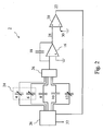
- the Fig. 2 shows a schematic view of a particular embodiment of the sensor 2 according to the invention, in which the influence of other dielectrics is taken into account by the control means 26 to provide the estimation signal 32. More precisely, it is the influence of the variations as a function of the temperature of the dielectric constant of the materials of the support of the measurement capacitors 4 and reference 6 which is taken into account.
- the spacers and other support elements making it possible to keep the parallel plates at a substantially constant distance of each other, in the case of an implementation by coaxial tubes, the support elements separating the two coaxial electrodes and, in the case of an implementation by nested combs placed on a dielectric substrate, the substrate itself. even.
- a first compensation capacitor 12 is presented on the Fig. 2 . It is disposed in the environment of the reservoir 24, that is to say in it or close to it, or in similar or identical environmental conditions, and is connected at its terminals to the Control means 26.
- the properties of the dielectric of the first compensation capacitor 12 evolve as a function of temperature, and possibly other factors, substantially in the same manner as the materials of the capacitor support. measurement 4 and reference 6, so as to mimic their evolution and to allow their taking into account and their compensation by the control means 26 to provide the estimation signal 32.
- the value of the capacitance of the first compensation capacitor 12 is estimated periodically during a given accumulation period by association with a discharge capacitor, for example the complementary standard capacitor 10. This value is used by the control means 26 for provide the estimation signal 32.
- the dielectric constant of the insulator forming the support which is for example a thermosetting resin reinforced or not, or a thermoplastic resin.
- the dielectric constant of such a material indeed varies in particular with the temperature and could, without this compensation, taint an estimate.
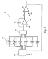
- the Fig. 3 shows a schematic view of a particular embodiment of the sensor 2 according to the invention, in which the influence of the variations as a function of the temperature of the dielectric constant of the support materials and the materials of the protective layers of the measurement capacitors 4 and reference 6 is taken into account.
- protective layer is meant, for example, a polymer-based or varnish-based insulation, which can be advantageously used for various reasons, or any another layer obtained in particular by surface treatment of the conductor, for example by controlled oxidation.
- a polymer-based or varnish-based insulation which can be advantageously used for various reasons, or any another layer obtained in particular by surface treatment of the conductor, for example by controlled oxidation.
- One reason may be in particular to avoid the effects of the capillarity of the liquid on the electrodes, this capillarity can indeed lead to estimation errors by modifying (either in more or less) in contact with the surface the actual height of the level of the liquid in the tank, especially in the case of implementation of capacitor of the comb type nested on plane substrate.
- another reason may be to avoid short circuits between the electrodes of the capacitor, during the insertion between them electrically conductive impurities.
- This protective layer degrades the accuracy of the measurement and its consideration improves accuracy.
- the estimation of the level 44 of the liquid can be done by adding to the sensor 2 any number of additional compensation capacitors, so as to take into account other parasitic capacitances, corresponding for example to the number of different media in the The environment of the physical part of the sensor 2.
- the influence of the electrical connections can for example also be the subject of such compensation.
- the control means 26 are able to provide on this basis an estimation signal 32 compensated for the reasons and in the manner explained below.
- the capacitance of a capacitor formed by two conductors to the potentials A and B and by n dielectrics is by decomposition into subdomains in each of which the permittivity of the dielectric is uniform (for example domains consisting of a single dielectric),
- This general formulation can sometimes be simplified when the geometry of the capacitor formed by the drivers meets certain conditions.
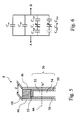
- the Fig. 5 shows a measurement capacitor 4 used according to a particular embodiment of the sensor 2 according to the invention and the Fig. 6 shows an example of an equivalent circuit of the measuring capacitor 4 of the Fig. 5 .
- This equivalent circuit can be used to design or / and program the control means 26 according to the invention.
- the measurement capacitor 4 is represented schematically and schematically on the Fig. 5 just like its model circuit or equivalent circuit on the Fig. 6 .
- the Fig. 5 and 6 are presented in more detail in the following.
- the Fig. 5 shows the two electrodes 46 of the measuring capacitor 4. They are separated by a distance d.
- a substrate or support material is disposed in an area 48, said area of the support material 48. This area covers an area S m (in section) and the filling material has a relative permittivity epsilon m .
- a protective layer is disposed in the zone 50, said zone of the protective layer 50. This zone covers an area S cp and the material filling it has a relative permittivity epsilon cp .
- the zone 56 said zone of variable capacity 56, has a variable capacity with the level 44 of the liquid and a shared area S u in operation between gas and liquid depending on the level 44 of the liquid.
- the variable capacity area 56 is separated into two parts: on the one hand, the zone 54 bathed by the liquid, of area S u ⁇ H where H is the relative height, and relative permittivity epsilon r and, secondly, the area 52 bathed by gas or air, of area S u ⁇ 1 - H and of relative permittivity substantially equal to 1.
- the capacitance of the measurement capacitor 4 that is to say the capacitance between the electrodes 46 represented on the Fig. 5 or the capacitance between terminals A and B on the equivalent circuit of the Fig. 6 , can be calculated by breaking down the capacitor and its four-part capacitance, corresponding to four parallel capacitances, of value:
- VS 12 epsilon 0 ⁇ epsilon m ⁇ S m d + epsilon cp ⁇ S cp d + S u ⁇ 1 - H ⁇ 2 ⁇ e epsilon cp + d - 2 ⁇ e - 1 + S u ⁇ H ⁇ 2 ⁇ e epsilon cp + d - 2 ⁇ e epsilon r - 1
- the relation which relates the relative height H of liquid to the value C 12 of the capacitance of the measurement capacitor 4 depends on the state of the liquid via epsilon r , as well as two other parameters epsilon m and epsilon cp resulting from the practical realization. of the sensor 2 via the materials used.
- the first compensation capacitor 12 is produced and adjoins the environment of the measurement capacitor 4 and the reference capacitor 6.
- This first compensation capacitor 12 thanks to the properties of its dielectric and thanks to its shape, imitates, possibly via a proportionality factor or an association function pre-established by prior measurement, the evolution as a function of the temperature, for example of the capacitance C 1 , and it simulates the capacitors with the same thicknesses and identical materials from identical fabrications.
- the measured capacity value at the terminals of the first compensation capacitor 12 is worth substantially VS 1 ' ⁇ epsilon 0 ⁇ epsilon m ⁇ S m d
- the value of the capacitance measured at the terminals of the second compensation capacitor 14 is substantially equal to VS 2 ' ⁇ epsilon 0 ⁇ epsilon cp ⁇ S cp d
- VS 120 epsilon 0 ⁇ epsilon m ⁇ S m d + epsilon cp ⁇ S cp d + S u ⁇ 2 ⁇ e epsilon cp + d - 2 ⁇ e - 1
- VS 110 epsilon 0 ⁇ epsilon m ⁇ S mr d + epsilon cp ⁇ S cpr d + S ur ⁇ 2 ⁇ e epsilon cp + d - 2 ⁇ e - 1
- VS 12 - VS 120 epsilon 0 ⁇ S u ⁇ H 2 ⁇ e epsilon cp + d - 2 ⁇ e e
- the senor 2 includes an electronic circuit disposed in the upper part of the sensor 2, so as to implement in particular the control means 26, and further includes a tracking track. conducting connection of the reference capacitor 6 to the electronic circuit.
- the influence of the parasitic capacitance generated by the presence of the connecting track is taken into account for the estimation of the level 44 of the liquid.
- connection track is materialized by a track or a cable arranged along the measurement capacitor 4, and which extends over the entire height of this capacitor and allows the transmission of the measurement of the capacitance of the reference capacitor 6 to the circuit .
- the connection track acts as an additional capacity which is added to the capacity of the reference capacitor 6. This parasitic capacitance varies according to the level 44 of the liquid since the track is disposed in the zone 56 of variable capacity.
- This sensor 2 makes it possible to improve the accuracy of the estimation of the level 44 of the liquid.
- the influence of the dielectrics or certain dielectrics structure is not compensated by the addition of compensation capacitors, but is taken into account by a prior calibration.
- the standard capacitor 8 acting as a discharge capacitor during an accumulation period and associated with a target capacitor whose value is a priori not known. is previously selected automatically, based on an initial measurement of the dielectric constant of the liquid, through the reference capacitor 6. This improves the accuracy of the measurement of the capacitance value of the target capacitor, for example measuring capacitor 4.
- the reference capacitor 6 is used to measure the level 44 of the liquid on the same height thereof.
- the reference capacitor 6 is conventionally intended to measure the dielectric constant variations of the liquid present in the tank 24 as a function of the temperature and the composition of the liquid. The very presence of this reference capacitor 6 prevents measuring the level 44 of liquid when this level is very low. However, it is possible to obtain a liquid level value 44, albeit with less precision, keeping in mind memory the value of the vacuum capacity during the first filling of the tank 24.
- the control means 26 operate differently when filling the tank 24 and during the descent of the liquid in the tank 24.
- the evolution of the level 44 of the liquid is much slower during the descent of the level 44 than when filling the tank 24.
- An adaptation of the succession of periods of accumulation and their duration depending on the type of process examined, a descent or rise of the level 44 of the liquid, can advantageously be integrated and implemented in the control means 26.
- the control means 26 are made in electronic form and the corresponding electronic part is disposed inside the tank 24, in the liquid or vapor phase, immediately near the reinforcements. This reduces the parasitic capacitances due to the length of the connections between the armatures and the electronic circuit, to reduce the influence of the temperature, to produce a single circuit board, in the case an implementation using printed circuits for the realization of the control means 26 and the measurement capacitors 4 and 6 in the reservoir 24, and simplify the manufacture while reducing costs.
- the senor 2 according to the invention can be used for example for a tank 24 of a vehicle, for example an automobile, and that the liquid can for example be fuel, including diesel, gasoline or liquefied petroleum gas.
- the expression "disposed in the tank 24" means both in the tank 24, but also at the edge of the tank 24 to the extent that the capacitance of the capacitors whose arrangement is concerned is influenced by significantly and measurably by the dielectric changes inside the tank 24.
- the expression "disposed in a lower part of the tank 24" means disposed sufficiently low in the latter so as to be able to generally provide a non-level dependent reference measurement 44, except possibly due to the effects of connection, and in operation. always always immersed, preferably.
- the reference capacitor 6 may also be for example disposed in the discharge pipe of the tank 24.
- the expression "of capacity greater than that of the measuring capacitor 4" means greater than the capacitance value of the measuring capacitor 4 under normal conditions of use, ie when the liquid has for example a dielectric constant of between 1 and 80 or about 80.
- control means 26 may in particular be electrical, electronic or computer means, made for example in the form of one or more electronic circuits or one or more microprocessors.
- the estimation signal 32 of the liquid level 44 can be either analog or digital without departing from the principle of the invention. If the control means 26 are in the form of an electronic circuit and the latter is disposed in the tank 24, an analogue signal that is not very sensitive to external disturbances or a digital signal is preferred according to an embodiment of the invention. invention for transmitting the tank estimation signal.
- the operational amplifier 16 and the comparator 20 may be arbitrary, regardless of their performance, their quality, their input and output impedance or their ideality.
- Load transfers can for example be implemented by a system of switched capacitors, non-overlapping cycles, to avoid possible short circuits and other inconveniences as explained above.
- the duration of accumulation periods may for example be 600 milliseconds. In general, the longer the period, the more accurate the measurement. Nevertheless, as it is often necessary to obtain a measure sufficiently regularly, to limit to a certain extent the duration of accumulation periods is unavoidable.
- the duration of the transient period before going into power and of charging the integration capacitor 18 from a zero value to the threshold voltage 20 may vary depending on the capacitance of the target capacitor and depending on the capacitance of the integration capacitor 18. This duration may for example be from 50 to 200 microseconds.
- the threshold voltage 30 can for example be 2.5 volts.
- an alert signal is provided, such that for example the presence of an undesirable liquid, such as water in the tank 24 can be communicated to the control systems of the vehicle.
Description
L'invention se rapporte à un capteur capacitif de niveau d'un liquide d'un réservoir, incluant un condensateur de mesure, destiné à être disposé dans le réservoir; un condensateur de référence, destiné à être disposé dans le réservoir dans une partie basse de celui-ci; un condensateur étalon, de capacité supérieure à celle du condensateur de mesure; des moyens de contrôle, aptes à fournir un signal d'estimation du niveau du liquide; un amplificateur opérationnel; un condensateur d'intégration, connecté entre l'entrée inverseuse de l'amplificateur et sa sortie; et un comparateur, destiné à comparer la tension de sortie de l'amplificateur à une tension de seuil et à fournir un signal de comparaison aux moyens de contrôle.The invention relates to a capacitive sensor of a liquid level of a reservoir, including a measuring capacitor, intended to be arranged in the reservoir; a reference capacitor, intended to be disposed in the reservoir in a lower part thereof; a standard capacitor with a capacitance greater than that of the measuring capacitor; control means capable of providing a signal for estimating the level of the liquid; an operational amplifier; an integration capacitor connected between the inverting input of the amplifier and its output; and a comparator for comparing the output voltage of the amplifier with a threshold voltage and providing a comparison signal to the control means.
L'invention se rapporte également à une méthode d'estimation du niveau d'un liquide dans un réservoir par mesure capacitive, et à l'utilisation d'un tel capteur capacitif de niveau pour un réservoir d'un véhicule.The invention also relates to a method for estimating the level of a liquid in a tank by capacitive measurement, and the use of such a level capacitive sensor for a tank of a vehicle.
On connaît de tels capteurs dans l'état de la technique.Such sensors are known in the state of the art.
La demande de brevet français
En outre, les condensateurs sont raccordés à un circuit électronique d'interprétation, comportant un microcontrôleur incorporant des moyens logiciels pour provoquer périodiquement la charge, par quantités discrètes, d'un intégrateur à partir d'une capacité à mesurer, puis la décharge de cet intégrateur à partir d'une capacité étalon placée dans le circuit, capacité étalon supérieure à toutes les capacités à mesurer. Un comparateur permet de comparer la quantité de charge de l'intégrateur avec une valeur de seuil, et permet la transmission, dès le dépassement de la valeur de seuil, d'un signal au microcontrôleur, ce qui entraîne le prélèvement d'une quantité d'électricité de l'intégrateur par la capacité étalon, de sorte que la charge moyenne de l'intégrateur reste quasiment constante. Le nombre de fois où le comparateur est à "1" pendant une période donnée permet d'estimer le niveau du liquide dans le réservoir.In addition, the capacitors are connected to an electronic interpretation circuit, comprising a microcontroller incorporating software means for periodically inducting, in discrete quantities, an integrator from a capacitance to be measured, and then discharging it. integrator from a standard capacitance placed in the circuit, higher standard capacity than all the capacities to be measured. A comparator makes it possible to compare the amount of load of the integrator with a threshold value, and allows the transmission, as soon as the threshold value is exceeded, of a signal to the microcontroller, which entails the collection of a quantity of integrator electricity by the standard capacity, so that the average load of the integrator remains almost constant. The number of times the comparator is at "1" during a given period makes it possible to estimate the level of the liquid in the tank.
Bien que de tels capteurs de l'état de la technique puissent bien fonctionner, il est observé qu'ils n'offrent pas des précisions suffisantes pour certaines applications, notamment quand le condensateur de mesure et le condensateur de référence ont des capacités de valeurs fort différentes ou quand il y a lieu d'estimer de très faibles valeurs de capacités par rapport à la valeur des capacités parasites, ce qui peut être le cas par exemple quand les dimensions du capteur sont petites ou quand la permittivité du liquide est faible par rapport à celle de l'eau à température ambiante.Although such sensors of the state of the art can work well, it is observed that they do not provide sufficient precision for certain applications, especially when the measuring capacitor and the reference capacitor have high value capabilities. different or when it is necessary to estimate very low capacitance values with respect to the value of parasitic capacitances, which may be the case for example when the dimensions of the sensor are small or when the permittivity of the liquid is low compared to to that of water at room temperature.
Un but de l'invention est de pallier les problèmes de l'état de la technique et en particulier de permettre l'obtention de mesures plus précises particulièrement pour les applications dans lesquelles le condensateur de mesure et le condensateur de référence ont des capacités de valeurs fort différentes.An object of the invention is to overcome the problems of the state of the art and in particular to make it possible to obtain more precise measurements, particularly for applications in which the measurement capacitor and the reference capacitor have value capacities. very different.
A cette fin, le capteur selon l'invention est caractérisé en ce qu'il inclut en outre un condensateur étalon complémentaire, de capacité supérieure à celle du condensateur de référence et différente de celle du condensateur étalon; en ce que les moyens de contrôle sont destinés à mettre en oeuvre les étapes suivantes, sur des périodes d'accumulation successives et pour un condensateur cible et un condensateur de décharge donnés à chaque période: une première étape de chargement du condensateur cible par application d'une tension donnée à ses bornes; une deuxième étape de transfert de la charge du condensateur cible vers le condensateur d'intégration; une troisième étape de décision, consistant à passer une quatrième étape si le signal de comparaison est négatif; la quatrième étape de décharge d'une partie de la charge du condensateur d'intégration dans le condensateur de décharge et ensuite de décharge complète du condensateur de décharge; et une cinquième étape de retour à la première étape; et en ce que les condensateurs cible et de décharge donnés à chaque période sont respectivement pris parmi un groupe de paires de condensateurs, incluant le condensateur de mesure et le condensateur étalon, et le condensateur de référence et le condensateur étalon complémentaire.For this purpose, the sensor according to the invention is characterized in that it further includes a complementary standard capacitor, with a capacity greater than that of the reference capacitor and different from that of the standard capacitor; in that the control means are intended to implement the following steps, over successive accumulation periods and for a given target capacitor and discharge capacitor at each period: a first step of charging the target capacitor by application of a voltage given at its terminals; a second step of transferring the charge from the target capacitor to the integration capacitor; a third decision step of passing a fourth step if the comparison signal is negative; the fourth step of discharging a portion of the charge of the integrating capacitor into the discharge capacitor and then completely discharging the discharge capacitor; and a fifth step back to the first step; and in that the target and discharge capacitors given at each period are respectively taken from a group of pairs of capacitors, including the measurement capacitor and the standard capacitor, and the reference capacitor and the complementary standard capacitor.
En opération, et plus particulièrement au cours d'une période d'accumulation donnée, la charge stockée dans le condensateur d'intégration du capteur selon l'invention varie au fur et à mesure des étapes successives mises en oeuvre par les moyens de contrôle, de sorte que cette charge atteigne un certain nombre de fois une valeur de charge donnée correspondant à une tension de sortie supérieure ou égale à la tension de seuil, et correspondant à un signal de comparaison positif. Ce nombre est substantiellement proportionnel au rapport entre la capacité moyenne du condensateur cible sur la période d'accumulation donnée et la capacité du condensateur de décharge, de valeur connue et substantiellement constante. Ce nombre permet ainsi aux moyens de contrôle d'estimer la capacité moyenne du condensateur cible sur la période d'accumulation donnée.In operation, and more particularly during a given accumulation period, the charge stored in the sensor integration capacitor according to the invention varies as the successive steps implemented by the control means, so that this charge reaches a given number of times a given charge value corresponding to an output voltage greater than or equal to the threshold voltage, and corresponding to a positive comparison signal. This number is substantially proportional to the ratio between the average capacitance of the target capacitor over the given accumulation period and the capacitance of the discharge capacitor, of known value and substantially constant. This number thus enables the control means to estimate the average capacitance of the target capacitor over the given accumulation period.
Le condensateur cible peut être le condensateur de mesure pour un certain nombre de périodes d'accumulation successives, pour ensuite être pour une période d'accumulation suivante le condensateur de référence. Quant au condensateur de décharge du capteur selon l'invention, contrairement aux capteurs de l'état de la techniques, il n'est pas indifféremment le même condensateur étalon que le condensateur cible soit le condensateur de mesure ou qu'il soit le condensateur de référence. Les condensateurs cible et de décharge donnés à chaque période d'accumulation sont respectivement pris parmi un groupe de paires de condensateurs, incluant le condensateur de mesure et le condensateur étalon, et le condensateur de référence et le condensateur étalon complémentaire. En d'autres termes, lors de l'estimation de la valeur de la capacité du condensateur de mesure, le condensateur étalon est utilisé comme condensateur de décharge, alors que, lors de l'estimation de la valeur de la capacité du condensateur de référence, le condensateur étalon complémentaire est utilisé comme condensateur de décharge.The target capacitor may be the measuring capacitor for a number of successive accumulation periods, and then for a subsequent accumulation period the reference capacitor. As for the discharge capacitor of the sensor according to the invention, unlike the sensors of the state of the art, it is not indifferently the same standard capacitor that the target capacitor is the measuring capacitor or that it is the capacitor of reference. The target and discharge capacitors given at each accumulation period are respectively taken from a group of pairs of capacitors, including the measurement capacitor and the standard capacitor, and the reference capacitor and the complementary standard capacitor. In other words, when estimating the capacitance value of the measuring capacitor, the standard capacitor is used as a discharge capacitor, whereas, when estimating the capacitance value of the reference capacitor, the complementary standard capacitor is used as the discharge capacitor.
Il est observé que cette association au condensateur cible d'un condensateur de décharge spécifique, c'est-à-dire l'association au condensateur de mesure du condensateur étalon et l'association au condensateur de référence du condensateur étalon complémentaire, permet d'obtenir des estimations plus précises. En effet, dans des conditions opérationnelles normales, le condensateur étalon a une capacité supérieure à celle du condensateur de mesure et le condensateur étalon complémentaire a une capacité supérieure à celle du condensateur de référence mais différente de celle du condensateur étalon. La capacité du condensateur étalon complémentaire est par exemple inférieure ou très inférieure à la valeur de la capacité du condensateur étalon.It is observed that this association with the target capacitor of a specific discharge capacitor, that is to say the association with the measuring capacitor of the standard capacitor and the association with the reference capacitor of the complementary standard capacitor, makes it possible to obtain more accurate estimates. Indeed, under normal operating conditions, the standard capacitor has a capacitance greater than that of the measuring capacitor and the complementary standard capacitor has a capacitance greater than that of the reference capacitor but different from that of the standard capacitor. The capacitance of the complementary standard capacitor is, for example, less than or much less than the capacitance value of the standard capacitor.
L'association d'un condensateur cible donné avec un condensateur de décharge spécifique permet quelle que soit la paire en question d'obtenir sur une période d'accumulation donnée un taux de dépassement de seuil par chargement suffisamment grand et il est observé dans ce cas des rapports de valeurs de capacités plus fins et plus une précision de mesure accrue. Le taux de dépassement de seuil est le rapport du nombre de dépassements de seuil sur le nombre total de chargements pour une période d'accumulation donnée, rapport qui est substantiellement égal au rapport entre la valeur de la capacité cible sur la valeur de la capacité de décharge.The combination of a given target capacitor with a specific discharge capacitor makes it possible, irrespective of the pair in question, to obtain, over a given accumulation period, a sufficiently large thresholding rate per loading, and this is observed in this case. reports of finer capacitance values and increased measurement accuracy. The threshold exceedance rate is the ratio of the number of threshold exceedances to the total number of loads for a given accumulation period, which is substantially equal to the ratio of the value of the target capacity to the value of the capacity of the discharge.
En d'autres termes, il est observé que plus proche est le condensateur cible du condensateur de référence, tout en restant toujours supérieur à celui-ci, plus précise est la mesure.In other words, it is observed that closer is the target capacitor of the reference capacitor, while still remaining higher than it, the more precise is the measurement.
Le capteur selon l'invention présente un avantage supplémentaire en ce sens qu'il permet une plus grande de liberté dans le choix des types de condensateurs de mesure et de référence lors de la conception du capteur lui-même. Le calibrage des mesures adapté à la valeur à mesurer permet d'obtention d'une meilleure précision dans les résultats, et une plus grande liberté dans la conception.The sensor according to the invention has an additional advantage in that it allows greater freedom in the choice of types of measurement and reference capacitors during the design of the sensor itself. Calibration of the measurements adapted to the value to be measured makes it possible to obtain a better precision in the results, and a greater freedom in the design.
Un autre objet de l'invention est de réduire les effets parasites des variations de température dus aux matériaux du support des condensateurs.Another object of the invention is to reduce the parasitic effects of temperature variations due to the materials of the capacitor support.
A cette fin, selon un mode particulier de réalisation, le capteur selon l'invention inclut en outre un premier condensateur de compensation, dont les caractéristiques évoluent en fonction de la température substantiellement de la même manière que les matériaux du support des condensateurs de mesure et de référence; et dans lequel le groupe de paires de condensateurs inclut en outre le premier condensateur de compensation et le condensateur étalon complémentaire.To this end, according to a particular embodiment, the sensor according to the invention further includes a first compensation capacitor, the characteristics of which change depending on the temperature substantially in the same way as the materials of the support of the measuring capacitors and reference; and wherein the group of capacitor pairs further includes the first compensation capacitor and the complementary standard capacitor.
Le rajout d'un premier condensateur de compensation et son appariement avec le condensateur étalon complémentaire permettent de mesurer les variations des propriétés du diélectrique du condensateur de compensation qui correspondent aux variations au cours du temps des matériaux du support des condensateurs de mesure et de référence. Ainsi, les moyens de contrôle peuvent intégrer une prise en compte de ces variations pour fournir le signal d'estimation.The addition of a first compensation capacitor and its pairing with the complementary standard capacitor make it possible to measure the variations in the properties of the dielectric of the compensation capacitor which correspond to the variations over time of the materials of the support of the measuring capacitors and of the capacitors. reference. Thus, the control means can incorporate a consideration of these variations to provide the estimation signal.
En d'autres termes, le premier condensateur de compensation, de par sa composition et sa forme, est destiné à imiter l'évolution de l'influence des composants diélectriques des matériaux du support des condensateurs de mesure et de référence, pour compenser cette influence. En d'autres termes encore, l'objectif est l'utilisation d'un modèle plus raffiné de la réalité, menant des estimations plus précises, mais rajoutant au système une inconnue, la constante diélectrique des matériaux du support, et la solution proposée par l'invention est de rajouter au système une équation, issue de l'expression mathématique de la capacité du premier condensateur de compensation, qui est fonction de la constante diélectrique des matériaux du support.In other words, the first compensation capacitor, by its composition and its shape, is intended to mimic the evolution of the influence of the dielectric components of the support materials of the measurement and reference capacitors, to compensate for this influence. . In other words again, the objective is the use of a more refined model of reality, leading to more accurate estimates, but adding to the system an unknown, the dielectric constant of the support materials, and the solution proposed by the invention is to add to the system an equation, derived from the mathematical expression of the capacitance of the first compensation capacitor, which is a function of the dielectric constant of the materials of the support.
Bien que cette résolution par mimétisme puisse paraître à première vue lourde et complexe afin d'améliorer la précision du signal d'estimation, le capteur selon l'invention et les étapes mises en oeuvre par les moyens de contrôle lors des périodes d'accumulation successives sont telles que le rajout d'une capacité d'un condensateur à mesurer rajoute très peu de complexité au capteur et à l'implémentation de ses moyens de contrôle, grâce à la nature flexible de la conception du capteur.Although this mimicry resolution may at first glance seem cumbersome and complex in order to improve the accuracy of the estimation signal, the sensor according to the invention and the steps implemented by the control means during successive accumulation periods. are such that the addition of a capacity of a capacitor to measure adds very little complexity to the sensor and the implementation of its control means, thanks to the flexible nature of the sensor design.
Aux fins seulement de bien comprendre le capteur selon l'invention par comparaison avec les systèmes de l'état de la technique, il est à noter que la demande internationale
Toujours dans le système de l'état de la technique, divulgué dans la demande internationale mentionnée ci-dessus, une fois la tension de mesure égale à 2 Volts, le temps pour arrivé est à cette tension est utilisé pour estimer la capacité du condensateur de mesure.Still in the state-of-the-art system, disclosed in the above-mentioned international application, once the measurement voltage is equal to 2 volts, the time for arrival is at this voltage is used to estimate the capacitance of the capacitor. measured.
Ce n'est pas l'approche du capteur de niveau selon l'invention. Le capteur de niveau selon l'invention fonctionne différemment, selon un des ces modes de réalisation, par adjonction d'un premier condensateur de compensation, qui, d'une certaine façon et comme expliqué plus haut, imite les variations dues au support pour les intégrer dans le calcul. Ceci permet la conception d'une architecture de capteur relativement simple. Les opérations de contrôle et de calibrage sont également réduites.This is not the approach of the level sensor according to the invention. The level sensor according to the invention operates differently, according to one of these embodiments, by adding a first compensation capacitor, which, in a certain way and as explained above, mimics the variations due to the support for them. integrate into the calculation. This allows the design of a relatively simple sensor architecture. Control and calibration operations are also reduced.
Un autre objet de l'invention est de réduire les effets parasites des variations de température dus aux matériaux des couches protectrices des condensateurs.Another object of the invention is to reduce the parasitic effects of temperature variations due to the materials of the protective layers of the capacitors.
A cette fin, selon un mode particulier de réalisation, le capteur selon l'invention inclut en outre un deuxième condensateur de compensation, dont les caractéristiques évoluent en fonction de la température substantiellement de la même manière respectivement que les matériaux des couches protectrices des condensateurs de mesure et de référence; et dans lequel le groupe de paires de condensateurs inclut en outre le deuxième condensateur de compensation et le condensateur étalon complémentaire.To this end, according to a particular embodiment, the sensor according to the invention further includes a second compensation capacitor, the characteristics of which change depending on the temperature substantially in the same way respectively as the materials of the protective layers of the capacitors of the capacitors. measurement and reference; and wherein the group of capacitor pairs further includes the second compensation capacitor and the complementary standard capacitor.
Ce mode particulier de réalisation de l'invention permet la compensation de la capacité parasite due aux matériaux des couches protectrices et surtout la compensation et la prise en compte des effets de la variation de celles-ci en fonction de la température.This particular embodiment of the invention allows the compensation of the parasitic capacitance due to the materials of the protective layers and especially the compensation and the taking into account of the effects of the variation thereof as a function of the temperature.
Ceci est applicable par exemple dans le cas où la sonde est un circuit imprimé avec des pistes en peignes imbriqués sur lesquelles sont ajoutés une couche isolante, par exemple de vernis, permettant d'éviter les courts-circuits.This is applicable for example in the case where the probe is a printed circuit with nested comb tracks on which are added an insulating layer, for example varnish, to avoid short circuits.
Les équations nécessaires permettant aux moyens de contrôle de fournir le signal d'estimation peuvent être trouvées en détaillant les circuits équivalents des différentes capacités, comme illustré et expliqué plus loin à titre d'exemple seulement, et en intégrant les solutions des équations résultantes dans les moyens de contrôle.The necessary equations enabling the control means to provide the estimation signal can be found by detailing the equivalent circuits of the different capacitors, as illustrated and explained later by way of example only, and integrating the solutions of the resulting equations into the equations. Control measures.
L'invention concerne également un capteur où sont combinés le premier condensateur de compensation et le deuxième condensateur de compensation, pour améliorer la précision par prise en compte de l'influence à la fois des matériaux du support et des couches protectrices.The invention also relates to a sensor in which the first compensation capacitor and the second compensation capacitor are combined, to improve the accuracy by taking into account the influence of both the support materials and the protective layers.
L'invention concerne également une méthode d'estimation du niveau d'un liquide dans un réservoir par mesure capacitive, incluant la mise en oeuvre des étapes suivantes, sur des périodes d'accumulation successives et pour un condensateur cible et un condensateur de décharge donnés à chaque étape : une première étape de chargement du condensateur cible par application d'une tension donnée à ses bornes; une deuxième étape de transfert de la charge du condensateur cible vers un condensateur d'intégration (18), connecté entre l'entrée inverseuse d'un amplificateur opérationnel et sa sortie; une troisième étape de décision, consistant à passer une quatrième étape si un signal de comparaison est négatif, le signal de comparaison étant fourni par un comparateur, destiné à comparer la tension de sortie de l'amplificateur à une tension de seuil; la quatrième étape de décharge d'une partie de la charge du condensateur d'intégration dans le condensateur de décharge et ensuite de décharge complète du condensateur de décharge; et une cinquième étape de retour à la première étape; les condensateurs cible et de décharge donnés à chaque période étant respectivement pris parmi un groupe de paires de condensateurs, incluant un condensateur de mesure, destiné à être disposé dans le réservoir, et un condensateur étalon, de capacité supérieure à celle du condensateur de mesure, et un condensateur de référence, destiné à être disposé dans le réservoir dans une partie basse de celui-ci, et le condensateur étalon complémentaire, de capacité supérieure à celle du condensateur de référence et différente de celle du condensateur étalon.The invention also relates to a method for estimating the level of a liquid in a tank by capacitive measurement, including the implementation of the following steps, over successive accumulation periods and for a given target capacitor and discharge capacitor. at each step: a first step of charging the target capacitor by applying a given voltage across its terminals; a second step of transferring the charge of the target capacitor to an integrating capacitor (18), connected between the inverting input of an operational amplifier and its output; a third decision step of passing a fourth step if a comparison signal is negative, the comparison signal being provided by a comparator, for comparing the output voltage of the amplifier to a threshold voltage; the fourth step of discharging a portion of the charge of the integrating capacitor into the discharge capacitor and then completely discharging the discharge capacitor; and a fifth step back to the first step; the target and discharge capacitors given at each period being respectively taken from a group of pairs of capacitors, including a measurement capacitor, intended to be arranged in the tank, and a standard capacitor, with a capacitance greater than that of the measurement capacitor, and a reference capacitor, intended to be disposed in the reservoir in a portion of the latter, and the complementary standard capacitor, of greater capacity than the reference capacitor and different from that of the standard capacitor.
Cette méthode permet d'estimer de manière plus précise le niveau de liquide dans le réservoir, tout en permettant des mises en oeuvre peu coûteuses et flexibles.This method makes it possible to estimate more precisely the level of liquid in the tank, while allowing inexpensive and flexible implementations.
L'invention concerne également l'utilisation d'un capteur tel que décrit ci-dessus, dans un réservoir d'un véhicule, par exemple un réservoir de carburant d'une automobile. Le capteur selon l'invention est particulièrement bien adapté à domaine d'application où les contraintes de coûts et de précision sont très importantes.The invention also relates to the use of a sensor as described above, in a tank of a vehicle, for example a fuel tank of an automobile. The sensor according to the invention is particularly well suited to the field of application where cost and precision constraints are very important.
Ces aspects ainsi que d'autres aspects de l'invention seront clarifiés dans la description détaillée de modes de réalisation particuliers de l'invention, référence étant faite aux dessins des figures, dans lesquelles :
- Fig. 1
- montre une vue schématique d'une réalisation particulière du capteur selon l'invention;
- Fig. 2
- et 3 montrent des vues schématiques d'autres réalisations particulières du capteur selon l'invention;
- Fig. 4
- montre une vue schématique des étapes mises en oeuvre, sur une période d'accumulation donnée, par les moyens de contrôle d'une réalisation particulière du capteur selon l'invention;
- Fig. 5
- montre un condensateur de mesure utilisé selon une réalisation particulière du capteur selon l'invention; et
- Fig. 6
- montre un exemple de circuit équivalent qui peut être utilisé pour concevoir ou programmer les moyens de contrôle selon l'invention.
- Fig. 1
- shows a schematic view of a particular embodiment of the sensor according to the invention;
- Fig. 2
- and 3 show schematic views of other particular embodiments of the sensor according to the invention;
- Fig. 4
- shows a schematic view of the steps implemented, over a given accumulation period, by the control means of a particular embodiment of the sensor according to the invention;
- Fig. 5
- shows a measurement capacitor used according to a particular embodiment of the sensor according to the invention; and
- Fig. 6
- shows an example of an equivalent circuit that can be used to design or program the control means according to the invention.
Les figures ne sont pas dessinées à l'échelle. Généralement, des éléments semblables sont dénotés par des références semblables dans les figures.The figures are not drawn to scale. Generally, similar elements are denoted by similar references in the figures.
La
La valeur de la capacité du condensateur de mesure 4 varie principalement en fonction du niveau du liquide dans le réservoir 24, c'est-à-dire de son niveau de remplissage, et mais également en fonction de la constante diélectrique du liquide en question. La valeur de la capacité du condensateur de référence 6 varie principalement en fonction de la constante diélectrique du liquide en question. En opération, le condensateur de référence 6 est destiné de préférence à être immergé en permanence dans le liquide. Les valeurs du condensateur étalon 8 et du condensateur étalon complémentaire 10 ne sont pas destinées à varier en fonction du niveau 44 du liquide ou de sa constante diélectrique. Ces dernières valeurs sont destinés à rester généralement constantes quelque soit les évolutions de niveau 44 ou de température dans le réservoir 24.The capacitance value of the measuring
L'amplificateur opérationnel 16 est connecté en sa borne inverseuse aux moyens de contrôle 26 et en sa borne non-inverseuse à une tension donnée en opération, par exemple à la masse. Il fournit une tension de sortie 28. Le condensateur d'intégration 18 est connecté entre la borne non-inverseuse et la sortie de l'amplificateur opérationnel 16.The
La tension de sortie 28 ou signal de sortie est fourni à la borne non-inverseuse du comparateur 20. En opération, une tension de seuil 30 est appliquée à la borne inverseuse du comparateur 20 de sorte que le signal de comparaison 22 est positif, ou égal à 1 par exemple, si la tension de sortie 28 est supérieure à la tension de seuil 30 et négatif, ou égal à 0 par exemple, dans le cas contraire.The
Par une connexion représentée dans la partie inférieure de la
En opération, et par référence à la fois à la
Par exemple, un certain nombre p de périodes d'accumulation associées au condensateur de mesure 4 peuvent avantageusement se succéder avant qu'ait lieu une période d'accumulation associée au condensateur de référence 6, suite à quoi le cycle peut reprendre. Ce mode de fonctionnement est adapté aux cas où le niveau 44 du liquide dans le réservoir 24 varie plus vite que ses propriétés diélectriques.For example, a number p of accumulation periods associated with the
A une période d'accumulation donnée, qui peut par exemple durer 600 millisecondes, sont toujours associés un condensateur dit cible (soit le condensateur de mesure 4 soit le condensateur de référence 6) et un condensateur dit de décharge (respectivement soit le condensateur étalon 8, soit le condensateur étalon complémentaire 10). Les couples, ou paires de condensateur, sont spécifiques et adaptés du point de vue de la valeur des capacités à mesurer, ce qui permet l'obtention d'une estimation plus précise du niveau 44 de liquide. Un condensateur étalon 8 et un condensateur étalon complémentaire 10, distincts, sont en effet choisis en raison de la différence importante entre les gammes des valeurs attendues de la capacité du condensateur de mesure 4 et des valeurs attendues de la capacité du condensateur de référence 6.At a given accumulation period, which may for example last 600 milliseconds, are always associated a so-called target capacitor (either the measuring
Lors d'une période d'accumulation, les moyens de contrôle 26 sont cadencées par une horloge et mettent en oeuvre les étapes suivantes. Le condensateur cible 4, 6 est, dans une première étape 34, électriquement chargé par application à ses bornes d'une tension déterminée. Ensuite, dans une deuxième étape 36, la charge du condensateur cible est transférée au condensateur d'intégration 18. Ceci peut par exemple être mis en oeuvre par un système d'interrupteurs à capacités commutées. Dans une troisième étape 38, le signal de comparaison 22 est examiné par les moyens de contrôle 26. S'il est positif, une quatrième étape 40 est mise oeuvre, consistant à décharger partiellement le condensateur d'intégration 18 dans le et grâce au condensateur de décharge 8, 10 et à ensuite décharger complètement le condensateur de décharge 8, 10. La première étape 34 et les suivantes sont alors mises en oeuvre à nouveau dans l'ordre, ce retour à la première étape 34 constituant la cinquième étape 42. Si le signal de comparaison 22 est négatif, la première étape 34 et les suivantes sont directement mises en oeuvre à nouveau; en d'autres termes, la quatrième étape 40 est passée et la cinquième étape 42, de retour, est directement mise en oeuvre.During a period of accumulation, the control means 26 are clocked and implement the following steps. The
Le nombre de dépassement de seuil nseuil , correspondant au nombre de fois que le signal de comparaison 22 est devenu positif sur une période d'accumulation donnée, est substantiellement égal au rapport de la valeur de la capacité du condensateur cible Ccible sur la valeur de la capacité du condensateur de décharge Cdécharge, le tout multiplié par le nombre de chargement ntotal du condensateur d'intégration 18. L'équation correspondante est 
Plus spécifiquement, en remplaçant respectivement la valeur de la capacité du condensateur cible par la valeur Cmesure de la capacité du condensateur de mesure 4 puis par la valeur Créférence de la capacité du condensateur de référence 6 et la valeur de la capacité du condensateur de décharge par la valeur Cétalon,8 de la capacité du condensateur étalon 8 puis par la valeur Cétalon,10 de la capacité du condensateur étalon complémentaire 10, on obtient 

En outre, le nombre de dépassement de seuil « à vide » nseuil,mesure,vide, c'est-à-dire lorsque le niveau 44 de liquide dans le réservoir 24 est inférieur à la limite inférieure du condensateur de mesure 4, celui-ci n'étant alors influencé que par le gaz au-dessus du liquide s'exprime de la même manière. On a 
Comme le niveau relatif h du liquide dans le réservoir 24 s'exprime substantiellement par l'expression suivante : 
on a ainsi : 
we thus have:
Le facteur k représente le facteur prenant en compte les variations des propriétés des diélectriques du condensateur de mesure 4 (variations dues à la composition du liquide, par exemple un carburant, ou de la température), c'est-à-dire principalement les variations de la constante diélectrique du liquide dont on mesure le niveau 44, compensé par l'estimation de la capacité du condensateur de référence 6. En définitive, on a 
où les nombres de dépassements de seuil « à vide » sont estimés avant le remplissage du réservoir 24, puis mémorisés par les moyens de contrôle 26 par exemple.The factor k represents the factor taking into account the variations of the properties of the dielectrics of the measurement capacitor 4 (variations due to the composition of the liquid, for example a fuel, or temperature), that is to say mainly the variations of the dielectric constant of the liquid whose
where the numbers of "empty" threshold exceedances are estimated before the filling of the
Les moyens de contrôle 26 peuvent par exemple être implémentées avec des interrupteurs à capacités commutées, à horloges non recouvrantes, pour éviter d'éventuels courts-circuits ou autres effets indésirables. Les moyens de contrôle 26 gèrent et mettent en oeuvre notamment à la fois les calculs d'estimation de niveau et les transferts de charge lors d'une période d'accumulation.The control means 26 may, for example, be implemented with switches with switched capacitors, with non-overlapping clocks, to avoid possible short circuits or other undesirable effects. The control means 26 manage and implement in particular both the level estimation calculations and the load transfers during a period of accumulation.
Les condensateurs de mesure 4 et de mesure 6 peuvent par exemple être physiquement des paires de plaques planes parallèles, des tubes coaxiaux ou des peignes imbriqués sur substrat plan ou circuit imprimé.The
Il est à noter encore qu'entre deux périodes d'accumulation, qu'une mesure sur une paire donnée de condensateur « cible, décharge » succède à une mesure sur la même paire ou à une mesure sur une autre paire, le condensateur d'intégration 18 peut ou non être déchargé dans l'intervalle entre les deux périodes d'accumulation.It should also be noted that between two periods of accumulation, a measurement on a given pair of capacitors "target, discharge" succeeds a measurement on the same pair or a measurement on another pair, the capacitor of
Le signal d'estimation 32 peut être utilisé par exemple pour indiquer ou afficher le niveau 44 du liquide dans le réservoir 24 ou pour piloter directement ou indirectement une électrovanne de remplissage du réservoir 24 ou tout autre actuateur, par exemple dans le but d'assurer la sécurité, notamment si le réservoir 24 est destiné à être un réservoir 24 de carburant d'un véhicule.The
Selon un mode de réalisation du capteur 2 selon l'invention, l'influence d'autres diélectriques est prise en compte pour fournir le signal d'estimation 32. Ces autres diélectriques peuvent notamment être propres à l'architecture de la partie du capteur 2 destinée à être en contact avec le liquide dans le réservoir 24, c'est-à-dire propres à l'agencement relatif des condensateurs de mesure 4 et de référence 6 et à leur conception physique.According to an embodiment of the
Deux modes de réalisations plus particuliers de ce mode sont décrits ci-dessus en faisant référence aux
La
Par matériaux du support, il faut entendre par exemple, dans le cas d'une implémentation des condensateurs de mesure 4 et de référence 6 par deux plaques planes parallèles, les entretoises et autres éléments de support permettant de maintenir les plaques parallèles à distance substantiellement constante l'une de l'autre, dans le cas d'une implémentation par tubes coaxiaux, les éléments de support séparant les deux électrodes coaxiales et, dans le cas d'une implémentation par peignes imbriqués posés sur un substrat diélectrique, le substrat lui-même.For support materials, for example, in the case of an implementation of the
Un premier condensateur de compensation 12 est présenté sur la
La valeur de la capacité du premier condensateur de compensation 12 est estimée périodiquement lors d'une période d'accumulation donnée par association avec un condensateur de décharge, par exemple le condensateur étalon complémentaire 10. Cette valeur est utilisée par les moyens de contrôle 26 pour fournir le signal d'estimation 32.The value of the capacitance of the
Selon ce mode de réalisation particulier peut par exemple être prise en compte l'influence des variations de la constante diélectrique de l'isolant formant le support, qui est par exemple en une résine thermodurcissable renforcée ou non, ou une résine thermoplastique. La constante diélectrique d'un tel matériau varie en effet sensiblement notamment avec la température et pourrait, sans cette compensation, entacher d'une erreur l'estimation.According to this particular embodiment can for example be taken into account the influence of the variations of the dielectric constant of the insulator forming the support, which is for example a thermosetting resin reinforced or not, or a thermoplastic resin. The dielectric constant of such a material indeed varies in particular with the temperature and could, without this compensation, taint an estimate.
La
Par couche protectrice, il faut entendre, par exemple, un isolant à base de polymère ou de vernis, qui peut être avantageusement utilisé pour diverses raisons, ou tout autre couche obtenue notamment par traitement de surface du conducteur par exemple par oxydation contrôlée. Une raison peut être notamment d'éviter les effets de la capillarité du liquide sur les électrodes, cette capillarité pouvant en effet entraîner des erreurs d'estimation en modifiant (soit en plus soit en moins) au contact de la surface la hauteur réelle du niveau du liquide dans le réservoir, spécialement dans des cas d'implémentation de condensateur du type par peignes imbriqués sur substrat plan. Comme déjà mentionné, une autre raison peut être d'éviter les courts-circuits entre les électrodes du condensateur, lors de l'insertion entre ceux-ci d'impuretés électriquement conductrices.By protective layer is meant, for example, a polymer-based or varnish-based insulation, which can be advantageously used for various reasons, or any another layer obtained in particular by surface treatment of the conductor, for example by controlled oxidation. One reason may be in particular to avoid the effects of the capillarity of the liquid on the electrodes, this capillarity can indeed lead to estimation errors by modifying (either in more or less) in contact with the surface the actual height of the level of the liquid in the tank, especially in the case of implementation of capacitor of the comb type nested on plane substrate. As already mentioned, another reason may be to avoid short circuits between the electrodes of the capacitor, during the insertion between them electrically conductive impurities.
Cette couche protectrice dégrade la précision de la mesure et sa prise en compte améliore la précision.This protective layer degrades the accuracy of the measurement and its consideration improves accuracy.
Par généralisation, l'estimation du niveau 44 du liquide peut se faire en adjoignant au capteur 2 un nombre quelconque de condensateurs de compensation supplémentaires, de manière à prendre en compte d'autres capacités parasites, correspondant par exemple au nombre de milieux différents dans l'environnement de la partie physique du capteur 2. L'influence des connexions électriques peut par exemple aussi faire l'objet d'une telle compensation.By generalization, the estimation of the
Les moyens de contrôle 26 sont capables de fournir sur cette base un signal d'estimation 32 compensé pour les raisons et selon les modalités expliquées ci-dessous.The control means 26 are able to provide on this basis an
La valeur d'une capacité C d'un condensateur vaut, d'une manière générale 
où les epsiloni représentent les constantes diélectriques des matériaux présents près des électrodes et où 
où Si, epsilon0 et ei représentent respectivement la surface des électrodes, la constante diélectrique de l'air ou du gaz présent au-dessus du liquide et l'entrefer correspondant à cet isolant i.where the epsilon i represent the dielectric constants of the materials present near the electrodes and where
where S i , epsilon O and e i respectively represent the surface of the electrodes, the dielectric constant of the air or gas present above the liquid and the air gap corresponding to this insulator i.
Selon le modèle électrostatique général et à partir de la loi de Gauss, de la relation de circulation du champ électrique et la définition de la capacité, la capacité d'un condensateur formé par de deux conducteurs aux potentiels A et B et par n diélectriques est, par décomposition en sous-domaines dans chacun desquels la permittivité du diélectrique est uniforme (par exemple des domaines constitués d'un seul diélectrique), 
Cette formulation générale peut parfois être simplifiée lorsque la géométrie du condensateur formé par les conducteurs respecte certaines conditions.This general formulation can sometimes be simplified when the geometry of the capacitor formed by the drivers meets certain conditions.
Par exemple, pour deux condensateurs infinis plans d'entrefer constant soumis à une différence de tension uniforme (montage en parallèle), on a 
Pour deux condensateurs cylindriques de longueur infinie en série, on a 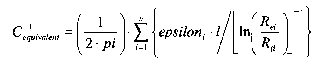
où Rei et Rii sont les rayons intérieur et extérieur du condensateur i formé par le diélectrique i.For two cylindrical capacitors of infinite length in series, we have
where R ei and R ii are the inner and outer radii of the capacitor i formed by the dielectric i .
D'une manière plus générale, on peut décomposer tout condensateur réel en un certain nombre de condensateurs élémentaires constitués d'un diélectrique homogène pour lesquels la capacité s'écrit 
pour toute géométrie des armatures. Il est ainsi possible d'écrire chacune des intégrations en un développement limité de termes dont le nombre peut être ajusté selon la précision souhaitée.More generally, one can decompose any real capacitor into a number of elementary capacitors consisting of a homogeneous dielectric for which the capacity is written
for any geometry of the frames. It is thus possible to write each of the integrations into a limited development of terms whose number can be adjusted according to the desired accuracy.
En première approximation sur les intégrales, par exemple, si le champ E est faiblement variable, on obtient 
d'où, il vient que 
et ![]()
from where, it comes that
and ![]()
Selon le modèle circuit, par ailleurs, lorsque l'on recompose le condensateur réel à partir des différents condensateurs élémentaires, on aboutit à un circuit représentatif où les capacités élémentaires sont agencées en série et/ou en parallèle. Ce type de problème est résoluble en utilisant la loi des mailles pour les branches en série et la loi des noeuds pour les branches en parallèle.According to the circuit model, on the other hand, when the real capacitor is recomposed from the different elementary capacitors, one ends up with a circuit representative where the elementary capacitors are arranged in series and / or in parallel. This type of problem is solvable by using the mesh law for the branches in series and the law of the nodes for the branches in parallel.
Pour l'exemple et à titre illustratif, la
Les
La zone 56, dite zone de capacité variable 56, a une capacité variable avec le niveau 44 du liquide et une aire Su partagée en opération entre gaz et liquide selon le niveau 44 du liquide. La zone de capacité variable 56 est séparée en deux parties: d'une part, la zone 54 baignée par le liquide, d'aire ![]()
où H est la hauteur relative, et de permittivité relative epsilonr et, d'autre part, la zone 52 baignée par le gaz ou l'air, d'aire ![]()
et de permittivité relative substantiellement égale à 1.The ![]()
where H is the relative height, and relative permittivity epsilon r and, secondly, the ![]()
and of relative permittivity substantially equal to 1.
La capacité du condensateur de mesure 4, c'est-à-dire la capacité entre les électrodes 46 représentées sur la 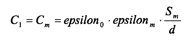


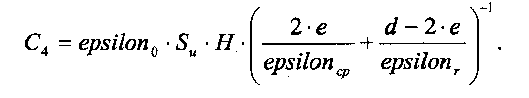
Ainsi, par addition, on obtient une expression mathématique de la valeur C12 de la capacité du condensateur de mesure 4 : 
Thus, by addition, a mathematical expression of the value C 12 of the capacitance of the
La relation qui relie la hauteur relative H de liquide à la valeur C12 de la capacité du condensateur de mesure 4 dépend de l'état du liquide via epsilonr, ainsi que de deux autres paramètres epsilonm et epsilon cp issus de la réalisation pratique du capteur 2 via les matériaux utilisés. De manière similaire, la valeur C11 de la capacité du condensateur de référence 6 s'écrit, en y adjoignant les indices "r", 
Par la mise en place judicieuse d'armatures ou par tout autre moyen, le premier condensateur de compensation 12 est réalisé et adjoint à l'environnement du condensateur de mesure 4 et du condensateur de référence 6. Ce premier condensateur de compensation 12, grâce aux propriétés de son diélectrique et grâce à sa forme, imite, éventuellement via un facteur de proportionnalité ou une fonction d'association préétablie par mesure préalable, l'évolution en fonction de la température par exemple de la capacité C1, et il simule les condensateurs avec les mêmes épaisseurs et des matières identiques issues de fabrications identiques. La valeur de la capacité mesurée aux bornes du premier condensateur de compensation 12 vaut substantiellement 
De même, la valeur de la capacité mesurée aux bornes du deuxième condensateur de compensation 14 vaut substantiellement 
Enfin, sachant, par mesure préalable, que les valeurs des capacités des condensateurs de mesure 4 et de référence 6, lorsque le réservoir 24 est complètement vide, sont respectivement substantiellement égales à 
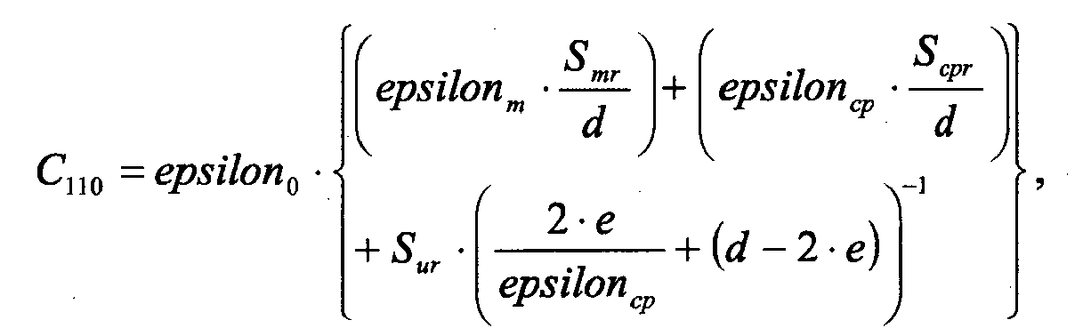
on obtient l'expression suivante 
et 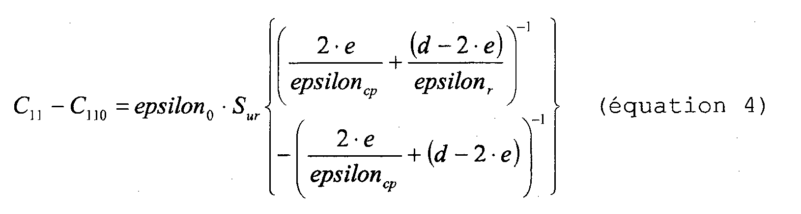
we get the following expression
and
On obtient ainsi un système de quatre équations linéaires (équations 1 à 4) à quatre inconnues, qui sont H, epsiloncp, epsilonr et epsilonm et pour lequel les méthodes de résolution sont bien connues. Celles-ci peuvent être avantageusement intégrées dans les moyens de contrôle 26.We thus obtain a system of four linear equations (
Ce raisonnement peut être généralisé. En effet, les condensateurs de forme quelconque peuvent être modélisés en superposant l'effet des différents domaines caractérisés par un seul diélectrique selon la formule générale ![]()
c'est-à-dire une dépendance linéaire de la capacité de ce condensateur avec la permittivité du milieu.This reasoning can be generalized. Indeed, the capacitors of any shape can be modeled by superimposing the effect of the different domains characterized by a single dielectric according to the general formula ![]()
that is to say a linear dependence of the capacity of this capacitor with the permittivity of the medium.
La mesure des différentes capacités judicieusement choisies permet donc de disposer d'un système d'équations linéaire résoluble. La résolution de ce système est donc possible et permet de calculer une estimation précise de la hauteur du liquide indépendamment des caractéristiques des diélectriques constituant la sonde de niveau et ce, quelque soit leur nombre.The measurement of the various judiciously chosen capacities thus makes it possible to have a system of solvable linear equations. The resolution of this system is therefore possible and makes it possible to calculate an accurate estimate of the height of the liquid independently of the characteristics of the dielectrics constituting the level probe, whatever their number.
Dans un mode de réalisation particulier du capteur 2 selon l'invention, le capteur 2 inclut un circuit électronique disposé dans la partie haute du capteur 2, de manière à mettre en oeuvre notamment les moyens de contrôle 26, et inclut en outre une piste de connexion menant du condensateur de référence 6 au circuit électronique. D'autre part selon ce mode de réalisation, l'influence de la capacité parasite engendrée par la présence de la piste de connexion est prise en compte pour l'estimation du niveau 44 du liquide.In a particular embodiment of the
Cette piste de connexion est matérialisée par une piste ou un câble disposé le long du condensateur de mesure 4, et qui s'étend sur toute la hauteur de ce condensateur et permet la transmission de la mesure de la capacité du condensateur de référence 6 au circuit. La piste de connexion agit comme une capacité additionnelle qui s'ajoute à la capacité du condensateur de référence 6. Cette capacité parasite varie en fonction du niveau 44 du liquide puisque la piste est disposée dans la zone 56 de capacité variable.This connection track is materialized by a track or a cable arranged along the
Par un raisonnement similaire à celui développé dans ce qui précède, un circuit équivalent à trois capacités en série peut être développé pour analyser l'influence de la piste de connexion sur la valeur mesurée de la capacité du condensateur de référence 6 et en compenser la présence dans les moyens de contrôle 26. Il sera clair pour l'homme du métier, au vu de ce qui précède, que le niveau 44 relatif de liquide peut être estimé par une fonction de plusieurs capacités correspondant notamment à l'influence de l'implémentation physique du capteur 2 et des constantes diélectriques de matériaux, moyennant l'adjonction de condensateur de compensation pour chacune des inconnues rajoutées, correspondant aux différents diélectriques présents dans la structure de la partie physique du capteur 2 ou avoisinant cette dernière et apparaissant dans le ou les équations à résoudre.By reasoning similar to that developed in the foregoing, a circuit equivalent to three capacitors in series can be developed to analyze the influence of the connection track on the measured value of the capacitance of the reference capacitor 6 and to compensate for its presence. in the control means 26. It will be clear to those skilled in the art, in view of the foregoing, that the
Ce capteur 2 permet d'améliorer la précision de l'estimation du niveau 44 du liquide.This
Selon un mode de réalisation du capteur 2 selon l'invention, l'influence des diélectriques ou de certains diélectriques de structure n'est pas compensée par l'adjonction de condensateurs de compensation, mais est prise en compte par un calibrage préalable.According to an embodiment of the
Selon un mode de réalisation du capteur 2 selon l'invention, le condensateur étalon 8, jouant le rôle de condensateur de décharge lors d'une période d'accumulation et étant associé à un condensateur cible dont la valeur n'est a priori pas connue, est sélectionné préalablement de manière automatique, en fonction d'une mesure initiale de la constante diélectrique du liquide, par le biais le condensateur de référence 6. Ceci améliore la précision de la mesure de la valeur de la capacité du condensateur cible, par exemple du condensateur de mesure 4.According to an embodiment of the
Selon un mode de réalisation du capteur 2 selon l'invention, le condensateur de référence 6 est utilisé pour mesurer le niveau 44 du liquide sur la hauteur même de celui-ci.According to an embodiment of the
Le condensateur de référence 6 a classiquement pour but de mesurer les variations de constante diélectrique du liquide présent dans le réservoir 24 en fonction de la température et de la composition du liquide. La présence même de ce condensateur de référence 6 empêche de mesurer le niveau 44 de liquide quand ce niveau est très bas. Il est toutefois possible d'obtenir une valeur de niveau 44 de liquide, certes avec une moindre précision, en gardant en mémoire la valeur de la capacité à vide lors du premier remplissage du réservoir 24.The reference capacitor 6 is conventionally intended to measure the dielectric constant variations of the liquid present in the
Selon un mode de réalisation du capteur 2 selon l'invention, les moyens de contrôle 26 fonctionnent différemment lors du remplissage du réservoir 24 et lors de la descente du liquide dans le réservoir 24. Dans les applications automobiles notamment et quand le réservoir 24 est un réservoir de carburant par exemple, l'évolution du niveau 44 du liquide est beaucoup plus lente lors de la descente du niveau 44 que lors du remplissage du réservoir 24. Une adaptation de la succession des périodes d'accumulation et de leur durée en fonction du type de processus examiné, une descente ou une montée du niveau 44 du liquide, peut avantageusement être intégrée et mise en oeuvre dans les moyens de contrôle 26.According to an embodiment of the
Selon un mode de réalisation du capteur 2 selon l'invention, les moyens de contrôle 26 sont réalisés sous forme électronique et la partie électronique correspondante est disposée à l'intérieur du réservoir 24, dans la phase liquide ou vapeur, immédiatement à proximité des armatures des condensateurs de référence 6 et de mesure 4. Ceci permet de réduire les capacités parasites dues à la longueur des connexions entre les armatures et le circuit électronique, de réduire l'influence de la température, de produire un seul circuit imprimé, dans le cas d'une implémentation utilisant des circuits imprimés pour la réalisation des moyens de contrôle 26 et des condensateurs de mesure 4 et de référence 6 dans le réservoir 24, et de simplifier la fabrication tout en diminuant les coûts.According to an embodiment of the
Il sera clair pour l'homme du métier que le capteur 2 selon l'invention peut être utilisé par exemple pour un réservoir 24 de véhicule, par exemple d'automobile, et que le liquide peut par exemple être du carburant, que ce soit notamment du gazole, de l'essence ou du gaz pétrole liquéfié.It will be clear to those skilled in the art that the
Dans le contexte de l'invention, l'expression « disposé dans le réservoir 24 » signifie à la fois dans le réservoir 24, mais aussi au bord du réservoir 24 dans la mesure où la capacité des condensateurs dont la disposition est concernée est influencée de manière significative et mesurable par les changements de diélectrique à l'intérieur du réservoir 24.In the context of the invention, the expression "disposed in the
L'expression « disposé dans une partie basse du réservoir 24 » signifie disposé suffisamment bas dans celui-ci de manière à être apte à fournir généralement une mesure de référence non dépendante du niveau 44, sauf éventuellement dû aux effets de connexion, et en opération en permanence toujours immergé, de préférence. Le condensateur de référence 6 peut aussi être par exemple disposé dans le conduit d'évacuation du réservoir 24.The expression "disposed in a lower part of the
Toujours dans le contexte de l'invention, l'expression « de capacité supérieure à celle du condensateur de mesure 4 » signifie supérieure à la valeur capacité du condensateur de mesure 4 dans des conditions normales d'utilisation, c'est-à-dire quand le liquide présente par exemple une constante diélectrique comprise entre 1 et 80 ou environ 80.Again in the context of the invention, the expression "of capacity greater than that of the measuring
Il sera clair pour l'homme du métier que les moyens de contrôle 26 peuvent être notamment des moyens électriques, électroniques ou informatiques, réalisés par exemple sous la forme d'un ou plusieurs circuits électroniques ou d'un ou plusieurs microprocesseurs.It will be clear to those skilled in the art that the control means 26 may in particular be electrical, electronic or computer means, made for example in the form of one or more electronic circuits or one or more microprocessors.
Il sera en outre clair pour l'homme du métier que le signal d'estimation 32 du niveau 44 du liquide peut être soit analogique, soit digital sans s'écarter du principe de l'invention. Si les moyens de contrôle 26 sont réalisés sous la forme d'un circuit électronique et que celui-ci est disposé dans le réservoir 24, un signal analogique peu sensible aux perturbations extérieures ou un signal digital sont préférés selon un mode de réalisation de l'invention pour transmettre le signal d'estimation du réservoir.It will further be clear to those skilled in the art that the
Il sera clair pour l'homme du métier que l'amplificateur opérationnel 16 et le comparateur 20 peuvent être quelconques, quel que soient leur réalisation, leur qualité, leur impédance d'entrée et de sortie ou leur idéalité.It will be clear to those skilled in the art that the
Les transferts de charge peuvent par exemple être mis en oeuvre par un système de capacités commutées, à cycles non-recouvrants, pour éviter d'éventuels courts-circuits et autres désagréments comme expliqués plus haut.Load transfers can for example be implemented by a system of switched capacitors, non-overlapping cycles, to avoid possible short circuits and other inconveniences as explained above.
La durée des périodes d'accumulation peut par exemple être de 600 millisecondes. En général, plus la période est longue, plus la mesure est précise. Néanmoins, comme il est souvent nécessaire d'obtenir une mesure suffisamment régulièrement, limiter dans une certaine mesure la durée des périodes d'accumulation est incontournable.The duration of accumulation periods may for example be 600 milliseconds. In general, the longer the period, the more accurate the measurement. Nevertheless, as it is often necessary to obtain a measure sufficiently regularly, to limit to a certain extent the duration of accumulation periods is unavoidable.
La durée de la période transitoire avant d'arriver en régime et consistant à charger le condensateur d'intégration 18 depuis une valeur nulle jusqu'à la tension de seuil 20 peut varier en fonction de la capacité du condensateur cible et en fonction de la capacité du condensateur d'intégration 18. Cette durée peut par exemple être de 50 à 200 microsecondes. La tension de seuil 30 peut quant à elle par exemple être de 2.5 volts.The duration of the transient period before going into power and of charging the
Selon un mode particulier de réalisation de la méthode selon l'invention, lorsqu'un niveau 44 atypique est estimé, un signal d'alerte est fourni, de sorte que par exemple la présence d'un liquide indésirable, tel que de l'eau, dans le réservoir 24 puisse être communiquée aux systèmes de contrôle du véhicule.According to a particular embodiment of the method according to the invention, when an
La présente invention n'est pas limitée par ce qui est en particulier illustré dans les dessins et par ce qui est en particulier décrit ci-dessus.The present invention is not limited by what is particularly illustrated in the drawings and by what is in particular described above.
Claims (11)
- Capacitive sensor (2) for detecting the level (44) of a liquid in a tank (24), including:· a measurement capacitor (4) intended to be placed in the tank (24);· a reference capacitor (6) intended to be placed in the tank (24) in a bottom part of the latter;· a calibration capacitor (8), having a capacitance higher than that of the measurement capacitor (4);· control means (26) capable of delivering an estimation signal (32) corresponding to the level (44) of the liquid;· an operational amplifier (16);· an integrating capacitor (18) connected between the inverting input of the amplifier (16) and its output; and· a comparator (20) intended for comparing the output voltage (28) of the amplifier (16) with a threshold voltage (30) and to deliver a comparison signal (22) to the control means (26);characterized in that it further includes a complementary calibration capacitor (10) having a capacitance higher than that of the reference capacitor (6) and different from that of the calibration capacitor (8);
in that the control means (26) are intended to implement, over successive accumulation periods and for a target capacitor and a discharge capacitor that are given for each period, the following steps:· a first step (34), for charging the target capacitor by applying a given voltage to its terminals;· a second step (36), for transferring the charge from the target capacitor to the integrating capacitor (18);· a third step (38), for deciding to skip the fourth step (40) if the comparison signal (22) is negative;· a fourth step (40), for discharging some of the charge of the integrating capacitor (18) into the discharge capacitor and then for completely discharging the discharge capacitor; and· a fifth step (42), for returning to the first step (34); andin that the target and discharge capacitors given at each period are taken respectively from a group of pairs of capacitors, including:· the measurement capacitor (4) and the calibration capacitor (8); and· the reference capacitor (6) and the complementary calibration capacitor (10). - Sensor (2) according to claim 1, in which the complementary calibration capacitor (10) has a capacitance lower than that of the calibration capacitor (8).
- Sensor (2) according to claim 1 or claim 2, which further includes a first compensating capacitor (12), the characteristics of which vary with temperature substantially in the same way as the materials of the support for the measurement (4) and reference (6) capacitors; and in which the group of pairs of capacitors further includes the first compensating capacitor (12) and an associated first discharge capacitor.
- Sensor (2) according to claim 3, in which the associated first discharge capacitor is the complementary calibration capacitor (10).
- Sensor (2) according to any one of the preceding claims, which further includes a second compensating capacitor (14), the characteristics of which vary with temperature substantially in the same manner as the materials of the protective layers of the measurement (4) and reference (6) capacitors, respectively, and in which the group of pairs of capacitors further includes the second compensating capacitor (14) and an associated second discharge capacitor.
- Sensor (2) according to claim 5, in which the associated second discharge capacitor is the complementary calibration capacitor (10).
- Sensor (2) according to any one of the preceding claims, in which the control means are intended to select the calibration capacitor (8), automatically, from among various capacitors, prior to the accumulation period associated with the measurement capacitor (4) according to an initial measurement of the dielectric constant of the liquid made on the reference capacitor (6).
- Sensor (2) according to any one of the preceding claims, in which the control means (26) are produced in the form of an electronic circuit placed inside the tank (24).
- Method of estimating the level (44) of a liquid in a tank (24) by a capacitive measurement, which includes the implementation, over successive accumulation periods and for a target capacitor and a discharge capacitor that are given for each step, the following steps:· a first step (34), for charging the target capacitor by applying a given voltage to its terminals;· a second step (36), for transferring the charge from the target capacitor to an integrating capacitor (18), connected between the inverting input of an operational amplifier (16) and its output;· a third step (38), for deciding to skip the fourth step (40) if a comparison signal (22) is negative, the comparison signal (22) being delivered by a comparator (20) intended to compare the output voltage (28) of the amplifier (16) with a threshold voltage (30);· a fourth step (40), for discharging some of the charge of the integrating capacitor (18) into the discharge capacitor and then for completely discharging the discharge capacitor; and· a fifth step (42), for returning to the first step (34) ;the target and discharge capacitors given at each period being taken respectively from a group of pairs of capacitors, including:· a measurement capacitor (4) intended to be placed in the tank (24), and a calibration capacitor (8) having a capacitance higher than that of the measurement capacitor (4); and· a reference capacitor (6) intended to be placed in the tank (24) in a bottom part of the latter, and the complementary calibration capacitor (10) having a capacitance higher than that of the reference capacitor (6) and different from that of the calibration capacitor (8).
- Method according to claim 9, in which a warning signal is delivered when an atypical level (44) is estimated.
- Use of a sensor (2) according to any one of claims 1 to 8 in a tank (24).
Priority Applications (1)
| Application Number | Priority Date | Filing Date | Title |
|---|---|---|---|
| EP05821694.6A EP1831652B1 (en) | 2004-12-22 | 2005-12-20 | Liquid level sensor and method of estimation |
Applications Claiming Priority (3)
| Application Number | Priority Date | Filing Date | Title |
|---|---|---|---|
| EP04106868A EP1677084A1 (en) | 2004-12-22 | 2004-12-22 | LIquid level sensor and method of estimation |
| EP05821694.6A EP1831652B1 (en) | 2004-12-22 | 2005-12-20 | Liquid level sensor and method of estimation |
| PCT/EP2005/056968 WO2006067149A2 (en) | 2004-12-22 | 2005-12-20 | Capacitive liquid level sensor and level-estimation method |
Publications (2)
| Publication Number | Publication Date |
|---|---|
| EP1831652A2 EP1831652A2 (en) | 2007-09-12 |
| EP1831652B1 true EP1831652B1 (en) | 2013-06-05 |
Family
ID=34930124
Family Applications (2)
| Application Number | Title | Priority Date | Filing Date |
|---|---|---|---|
| EP04106868A Pending EP1677084A1 (en) | 2004-12-22 | 2004-12-22 | LIquid level sensor and method of estimation |
| EP05821694.6A Not-in-force EP1831652B1 (en) | 2004-12-22 | 2005-12-20 | Liquid level sensor and method of estimation |
Family Applications Before (1)
| Application Number | Title | Priority Date | Filing Date |
|---|---|---|---|
| EP04106868A Pending EP1677084A1 (en) | 2004-12-22 | 2004-12-22 | LIquid level sensor and method of estimation |
Country Status (7)
| Country | Link |
|---|---|
| US (1) | US7845224B2 (en) |
| EP (2) | EP1677084A1 (en) |
| JP (1) | JP2008524619A (en) |
| KR (1) | KR101264943B1 (en) |
| CN (1) | CN100473954C (en) |
| BR (1) | BRPI0519379A2 (en) |
| WO (1) | WO2006067149A2 (en) |
Families Citing this family (33)
| Publication number | Priority date | Publication date | Assignee | Title |
|---|---|---|---|---|
| FR2892509B1 (en) | 2005-10-26 | 2007-12-21 | Inergy Automotive Systems Res | CAPACITIVE GAUGE FOR FUEL TANK |
| KR20080063358A (en) * | 2005-10-26 | 2008-07-03 | 이너지 오토모티브 시스템즈 리서치 (소시에떼 아노님) | Capacitive gauge |
| US8181516B2 (en) | 2006-10-26 | 2012-05-22 | Inergy Automotive Systems Research (Societe Anonyme) | Measuring a liquid level in a tank with two measurement capacitors and two reference capacitors |
| US8093914B2 (en) * | 2007-12-14 | 2012-01-10 | Cypress Semiconductor Corporation | Compensation circuit for a TX-RX capacitive sensor |
| CA2629960C (en) * | 2008-04-28 | 2009-12-08 | Westport Power Inc. | Apparatus and method for improving the accuracy of measurements taken with a capacitance-type sensor |
| US8237456B2 (en) | 2009-03-02 | 2012-08-07 | Atmel Corporation | Capacitive sensing |
| EP2228628B1 (en) * | 2009-03-10 | 2011-09-28 | EM Microelectronic-Marin SA | Electronic circuit with a capacitive sensor for measuring a physical parameter, and method for activating the electronic circuit |
| US8281655B2 (en) * | 2009-04-03 | 2012-10-09 | Eaton Corporation | Fuel gauging system utilizing a digital fuel gauging probe |
| US8225654B2 (en) * | 2009-07-01 | 2012-07-24 | Tecan Trading Ag | Self-compensating capacitive liquid level detector |
| CH702180B1 (en) * | 2009-11-02 | 2015-02-13 | Tecan Trading Ag | Method for testing a laboratory device and corresponding laboratory device. |
| US8604774B2 (en) * | 2010-12-07 | 2013-12-10 | Himax Technologies Limited | Current sensing circuit with feedback control and dual capacitor set range setting |
| DE102010062622A1 (en) * | 2010-12-08 | 2012-06-14 | Ifm Electronic Gmbh | Method for self-monitoring of a ceramic pressure measuring cell of a capacitive pressure sensor and an evaluation circuit for carrying out the method |
| CN102116663B (en) * | 2010-12-20 | 2012-05-30 | 皇明太阳能股份有限公司 | Gradient type capacitance sensor |
| KR101856279B1 (en) | 2011-06-27 | 2018-05-09 | 휴렛-팩커드 디벨롭먼트 컴퍼니, 엘.피. | Ink level sensor and related methods |
| KR20130068790A (en) * | 2011-12-16 | 2013-06-26 | 에이디반도체(주) | Level sensor using electrostatic capacity and method for sensing of level |
| AT513452B1 (en) * | 2012-10-05 | 2014-08-15 | Ait Austrian Inst Technology | Dispensing device for medicaments |
| CN102944286B (en) * | 2012-11-14 | 2015-06-10 | 北京信息科技大学 | Liquid level detecting circuit and detecting method |
| CN102997974B (en) * | 2012-12-24 | 2014-12-10 | 电子科技大学 | Adaptive capacitance liquid level meter |
| US10203238B2 (en) | 2014-03-07 | 2019-02-12 | Barrelogix, Llc | Liquid detection apparatus |
| CA2944616A1 (en) | 2014-03-31 | 2015-10-08 | University Of Utah Research Foundation | Fluid analysis device and associated systems and methods |
| CN104020358B (en) * | 2014-06-10 | 2016-09-28 | 济南大学 | A kind of measure dielectric permittivity and the method for liquid level in LNG gas tank |
| US10451467B2 (en) * | 2014-10-08 | 2019-10-22 | Semiconductor Components Industries, Llc | Level sensor and method |
| WO2016068913A1 (en) | 2014-10-29 | 2016-05-06 | Hewlett-Packard Development Company, L.P. | Fluid ejection device with printhead ink level sensor |
| CN106194738A (en) * | 2015-05-08 | 2016-12-07 | 丹佛斯(天津)有限公司 | Supervising device and monitoring method |
| US10448875B2 (en) | 2015-10-15 | 2019-10-22 | Stream DX, Inc | Capacitive measurement device with integrated electrical and mechanical shielding |
| US10499573B1 (en) | 2016-05-16 | 2019-12-10 | Keith Lynn Paulsen | Wireless soil profile monitoring apparatus and methods |
| US10228340B2 (en) * | 2016-05-16 | 2019-03-12 | Keith Lynn Paulsen | Wireless soil profile monitoring apparatus and methods |
| GB2550402B (en) | 2016-05-19 | 2022-04-20 | Ultra Electronics Ltd | Circuit for simulating a capacitance fuel probe |
| WO2018217818A1 (en) | 2017-05-22 | 2018-11-29 | Stream DX, Inc | Capacitive measurement device with minimized sensitivity to manufacturing variability and environmental changes |
| EP3543716B1 (en) * | 2018-01-24 | 2021-03-03 | Shenzhen Goodix Technology Co., Ltd. | Capacitance detection circuit, touch apparatus, and terminal device |
| CN108896131B (en) * | 2018-05-08 | 2019-11-26 | 鲁东大学 | Level gauging unit and material level gauge in RF admittance level meter based on temperature-compensating |
| CN108645481B (en) * | 2018-06-22 | 2021-03-16 | 华帝股份有限公司 | Non-contact capacitance liquid level detection method |
| CN112161673B (en) * | 2020-09-15 | 2022-06-17 | 厦门晶尊微电子科技有限公司 | Accurate capacitive liquid level detection circuit and adjustment mode |
Family Cites Families (37)
| Publication number | Priority date | Publication date | Assignee | Title |
|---|---|---|---|---|
| US3801902A (en) * | 1972-07-27 | 1974-04-02 | Gull Airborne Instruments Inc | Electrical measuring apparatus employing a plurality of condition responsive devices |
| CA1070780A (en) * | 1976-06-16 | 1980-01-29 | Canadian General Electric Company Limited | Two wire multiple switching system |
| GB1601338A (en) * | 1977-03-14 | 1981-10-28 | Huddart R | Measuring apparatus using parameter dependant capacitance |
| US4259865A (en) * | 1978-10-12 | 1981-04-07 | Smiths Industries Limited | Fluid-gauging systems |
| FR2447555A1 (en) | 1979-01-26 | 1980-08-22 | Jaeger | Electronic circuit for liq. level measurement - utilises capacitor charged and discharged with constant current for comparison with reference |
| US4214479A (en) * | 1979-05-21 | 1980-07-29 | Simmonds Precision Products, Inc. | Capacitive type fuel probe compensation circuit |
| GB2058364B (en) | 1979-09-01 | 1983-03-23 | Ferranti Ltd | Capacitance measuring apparatus |
| US4388828A (en) * | 1980-05-14 | 1983-06-21 | Honeywell Inc. | Liquid gaging system sensor calibration |
| US4444051A (en) * | 1981-03-18 | 1984-04-24 | Nissan Motor Company, Limited | Electronic liquid level gauge |
| JPS59501835A (en) * | 1982-09-30 | 1984-11-01 | ザ ボ−イング カンパニ− | fuel gauge |
| DE3610166A1 (en) * | 1985-04-03 | 1986-10-09 | Smiths Industries Public Ltd. Co., London | LEVEL MEASURING DEVICE |
| DE3778094D1 (en) * | 1986-08-01 | 1992-05-14 | Siemens Ag | METHOD AND DEVICE FOR DETECTING THE POLARITY OF POLED CAPACITORS. |
| US4947689A (en) * | 1989-01-13 | 1990-08-14 | Hochstein Peter A | Capacitive liquid sensor |
| US5451940A (en) * | 1989-12-20 | 1995-09-19 | Endress U. Hauser Gmbh U. Co. | Capacitive sensor signal processing arrangement using switch capacitor structures |
| SU1767451A1 (en) | 1990-05-03 | 1992-10-07 | Институт Автоматики Ан Киргсср | Metering transducer with capacity sensor |
| US5042299A (en) * | 1990-07-23 | 1991-08-27 | Iimorrow, Inc. | Capacitive fluid level sensor |
| DE4031210A1 (en) * | 1990-10-04 | 1992-04-09 | Bosch Gmbh Robert | CAPACITIVE SENSOR FOR MEASURING A FUEL WALL FILM |
| DE4237196C1 (en) | 1992-11-04 | 1994-02-10 | Vega Grieshaber Gmbh & Co | Method and arrangement for measuring at least one capacitance |
| US5461321A (en) | 1993-09-17 | 1995-10-24 | Penberthy, Inc. | Apparatus and method for measuring capacitance from the duration of a charge-discharge charge cycle |
| DE4340472C1 (en) | 1993-11-27 | 1995-04-06 | Grieshaber Vega Kg | Method and circuit arrangement for measuring a capacitance |
| US5613398A (en) * | 1994-01-24 | 1997-03-25 | Chrysler Corporation | Smart fuel tank module |
| JP3216955B2 (en) * | 1994-05-31 | 2001-10-09 | 株式会社日立製作所 | Capacitive sensor device |
| DE4421906C2 (en) * | 1994-06-24 | 1996-10-24 | Vdo Schindling | Method and circuit arrangement for measuring the resistance of a resistance sensor |
| US5576628A (en) * | 1994-09-30 | 1996-11-19 | Telcom Semiconductor, Inc. | Method and apparatus to measure capacitance |
| US5661240A (en) * | 1995-09-25 | 1997-08-26 | Ford Motor Company | Sampled-data interface circuit for capacitive sensors |
| KR100211114B1 (en) | 1997-05-27 | 1999-07-15 | 허금자 | Liquid level detector |
| EP0931244A1 (en) * | 1997-06-12 | 1999-07-28 | Andrew M. Matulek | Capacitive liquid level indicator |
| WO1999010714A1 (en) | 1997-08-25 | 1999-03-04 | Millennium Sensors Ltd. | A compensated capacitive liquid level sensor |
| AU4717799A (en) | 1998-06-24 | 2000-01-10 | Cordant Technologies, Inc. | Monitoring liquid level in a container with a capacitive transducer |
| FR2795816B1 (en) * | 1999-07-02 | 2001-09-28 | Roxer | LEVEL SENSOR |
| US6502460B1 (en) * | 2000-01-11 | 2003-01-07 | Delphi Technologies, Inc. | Fluid level measuring system |
| JP3662808B2 (en) | 2000-04-14 | 2005-06-22 | 理想科学工業株式会社 | Liquid detection method and liquid detection apparatus |
| ES2245362T3 (en) | 2000-04-14 | 2006-01-01 | Robertshaw Controls Company | CIRCUIT AND SYSTEM FOR MEASURING THE LEVEL OF CAPACITY. |
| JP2001343273A (en) | 2000-05-31 | 2001-12-14 | Nippon Parkerizing Co Ltd | Capacitance type sensor for detecting fine particles |
| US6781388B2 (en) * | 2001-09-26 | 2004-08-24 | Delphi Technologies, Inc. | Liquid property sensor |
| DE102004006020A1 (en) * | 2004-02-06 | 2005-08-25 | E + E Elektronik Ges.M.B.H. | Circuit arrangement for capacitive humidity measurement and method for operating the same |
| JP4310695B2 (en) * | 2004-03-30 | 2009-08-12 | アイシン精機株式会社 | Capacitance change detection device |
-
2004
- 2004-12-22 EP EP04106868A patent/EP1677084A1/en active Pending
-
2005
- 2005-12-20 WO PCT/EP2005/056968 patent/WO2006067149A2/en active Application Filing
- 2005-12-20 CN CNB2005800475813A patent/CN100473954C/en not_active Expired - Fee Related
- 2005-12-20 BR BRPI0519379-6A patent/BRPI0519379A2/en active Search and Examination
- 2005-12-20 US US11/793,542 patent/US7845224B2/en not_active Expired - Fee Related
- 2005-12-20 JP JP2007547491A patent/JP2008524619A/en active Pending
- 2005-12-20 EP EP05821694.6A patent/EP1831652B1/en not_active Not-in-force
- 2005-12-20 KR KR1020077014366A patent/KR101264943B1/en not_active IP Right Cessation
Also Published As
| Publication number | Publication date |
|---|---|
| JP2008524619A (en) | 2008-07-10 |
| EP1831652A2 (en) | 2007-09-12 |
| WO2006067149A3 (en) | 2006-08-24 |
| WO2006067149A2 (en) | 2006-06-29 |
| CN101128722A (en) | 2008-02-20 |
| BRPI0519379A2 (en) | 2009-01-20 |
| CN100473954C (en) | 2009-04-01 |
| EP1677084A1 (en) | 2006-07-05 |
| KR20070091155A (en) | 2007-09-07 |
| KR101264943B1 (en) | 2013-05-15 |
| US7845224B2 (en) | 2010-12-07 |
| US20090120159A1 (en) | 2009-05-14 |
Similar Documents
| Publication | Publication Date | Title |
|---|---|---|
| EP1831652B1 (en) | Liquid level sensor and method of estimation | |
| EP1831653B1 (en) | Flüssigkeitspegelsensor | |
| EP1835263B1 (en) | Electronic interface circuit of a capacitive sensor for measuring a physical parameter, and method of activation of the electronic circuit | |
| EP1784480B1 (en) | Method and device for biomass determination in a medium, in particular a medium containing biological cells, and measurement apparatus implementing said method | |
| FR3029298A1 (en) | AUTOMATIC METHOD OF ESTIMATING THE CHARGING STATE OF A CELL OF A BATTERY | |
| EP0612982B1 (en) | Conditioning circuit for analogue resistance sensor, especially for fuel gauge | |
| EP0613012A1 (en) | Capacitive accelerometer with circuit for correcting the disturbing effects of parasitic capacitances | |
| EP3026430A1 (en) | Method for imaging a medium by electrical measurements with contact impedance correction | |
| FR3090117A1 (en) | ESH ESTIMATION AND SOC ESTIMATE OF AN ELECTROCHEMICAL ELEMENT | |
| FR2985017A1 (en) | DEVICE FOR MEASURING A VARIATION OF LOW CONSUMPTION CAPACITY AND ASSOCIATED METHOD | |
| EP2834658A1 (en) | Method and device for measuring a magnetic field and the temperature of a magneto-resistive transducer | |
| FR2795816A1 (en) | LEVEL SENSOR | |
| EP3737920B1 (en) | Device for capacitive measurements in a multi-phase medium | |
| EP3414578B1 (en) | Device for measuring an electrical quantity of one phase of an ac electric current of an overhead electrical network | |
| WO2016102823A1 (en) | Method for estimating characteristic physical quantities of an electric battery | |
| EP1336082B1 (en) | Capacitive measurement device | |
| EP0193421A1 (en) | Capacitance-frequency transducer, especially for capacitance sensors | |
| FR3045218A1 (en) | DETERMINATION OF PARAMETERS OF A DYNAMIC MODEL FOR AN ELECTROCHEMICAL BATTERY CELL | |
| FR2898985A1 (en) | Electric energy storage unit`s e.g. lead-acid type battery, health state determining method, involves determining two derivatives of voltage response to exciting current, and determining health state of unit with respect to derivatives | |
| FR2654834A1 (en) | Capacitive probe for the in situ measurement of the water content of soil | |
| FR2817036A1 (en) | Measurement sensor based on an indirect measurement of the permitivity between two electrically conducting bodies, has a broad dynamic response | |
| EP2251773B1 (en) | Method of validating coordinate data determined by a resistive touch surface, and of discarding erroneous coordinate data | |
| WO2009112179A1 (en) | Device for measuring a capacity variation, capacitive sensor including such device, and related method | |
| FR3096775A1 (en) | Device for capacitive measurements of the height of a fluid in a reservoir | |
| FR2890762A1 (en) | Force sensing resistor`s linear position determining device for motor vehicle, has unit calculating position relative to support on semiconductor support based on measured voltage if resistor output is coupled to ground and supply potential |
Legal Events
| Date | Code | Title | Description |
|---|---|---|---|
| PUAI | Public reference made under article 153(3) epc to a published international application that has entered the european phase |
Free format text: ORIGINAL CODE: 0009012 |
|
| 17P | Request for examination filed |
Effective date: 20070723 |
|
| AK | Designated contracting states |
Kind code of ref document: A2 Designated state(s): AT BE BG CH CY CZ DE DK EE ES FI FR GB GR HU IE IS IT LI LT LU LV MC NL PL PT RO SE SI SK TR |
|
| RIN1 | Information on inventor provided before grant (corrected) |
Inventor name: BARLESI, LORENZO Inventor name: CHIAFFI, MICHEL Inventor name: NAYDENOV, VOLODIA |
|
| DAX | Request for extension of the european patent (deleted) | ||
| GRAP | Despatch of communication of intention to grant a patent |
Free format text: ORIGINAL CODE: EPIDOSNIGR1 |
|
| GRAS | Grant fee paid |
Free format text: ORIGINAL CODE: EPIDOSNIGR3 |
|
| GRAA | (expected) grant |
Free format text: ORIGINAL CODE: 0009210 |
|
| AK | Designated contracting states |
Kind code of ref document: B1 Designated state(s): AT BE BG CH CY CZ DE DK EE ES FI FR GB GR HU IE IS IT LI LT LU LV MC NL PL PT RO SE SI SK TR |
|
| REG | Reference to a national code |
Ref country code: GB Ref legal event code: FG4D Free format text: NOT ENGLISH |
|
| REG | Reference to a national code |
Ref country code: CH Ref legal event code: EP |
|
| REG | Reference to a national code |
Ref country code: AT Ref legal event code: REF Ref document number: 615921 Country of ref document: AT Kind code of ref document: T Effective date: 20130615 |
|
| REG | Reference to a national code |
Ref country code: IE Ref legal event code: FG4D Free format text: LANGUAGE OF EP DOCUMENT: FRENCH |
|
| REG | Reference to a national code |
Ref country code: DE Ref legal event code: R096 Ref document number: 602005039918 Country of ref document: DE Effective date: 20130801 |
|
| REG | Reference to a national code |
Ref country code: AT Ref legal event code: MK05 Ref document number: 615921 Country of ref document: AT Kind code of ref document: T Effective date: 20130605 |
|
| PG25 | Lapsed in a contracting state [announced via postgrant information from national office to epo] |
Ref country code: ES Free format text: LAPSE BECAUSE OF FAILURE TO SUBMIT A TRANSLATION OF THE DESCRIPTION OR TO PAY THE FEE WITHIN THE PRESCRIBED TIME-LIMIT Effective date: 20130916 Ref country code: AT Free format text: LAPSE BECAUSE OF FAILURE TO SUBMIT A TRANSLATION OF THE DESCRIPTION OR TO PAY THE FEE WITHIN THE PRESCRIBED TIME-LIMIT Effective date: 20130605 Ref country code: LT Free format text: LAPSE BECAUSE OF FAILURE TO SUBMIT A TRANSLATION OF THE DESCRIPTION OR TO PAY THE FEE WITHIN THE PRESCRIBED TIME-LIMIT Effective date: 20130605 Ref country code: FI Free format text: LAPSE BECAUSE OF FAILURE TO SUBMIT A TRANSLATION OF THE DESCRIPTION OR TO PAY THE FEE WITHIN THE PRESCRIBED TIME-LIMIT Effective date: 20130605 Ref country code: SI Free format text: LAPSE BECAUSE OF FAILURE TO SUBMIT A TRANSLATION OF THE DESCRIPTION OR TO PAY THE FEE WITHIN THE PRESCRIBED TIME-LIMIT Effective date: 20130605 Ref country code: GR Free format text: LAPSE BECAUSE OF FAILURE TO SUBMIT A TRANSLATION OF THE DESCRIPTION OR TO PAY THE FEE WITHIN THE PRESCRIBED TIME-LIMIT Effective date: 20130906 Ref country code: SE Free format text: LAPSE BECAUSE OF FAILURE TO SUBMIT A TRANSLATION OF THE DESCRIPTION OR TO PAY THE FEE WITHIN THE PRESCRIBED TIME-LIMIT Effective date: 20130605 |
|
| REG | Reference to a national code |
Ref country code: NL Ref legal event code: VDEP Effective date: 20130605 |
|
| REG | Reference to a national code |
Ref country code: LT Ref legal event code: MG4D |
|
| PG25 | Lapsed in a contracting state [announced via postgrant information from national office to epo] |
Ref country code: BG Free format text: LAPSE BECAUSE OF FAILURE TO SUBMIT A TRANSLATION OF THE DESCRIPTION OR TO PAY THE FEE WITHIN THE PRESCRIBED TIME-LIMIT Effective date: 20130905 Ref country code: PL Free format text: LAPSE BECAUSE OF FAILURE TO SUBMIT A TRANSLATION OF THE DESCRIPTION OR TO PAY THE FEE WITHIN THE PRESCRIBED TIME-LIMIT Effective date: 20130605 |
|
| PG25 | Lapsed in a contracting state [announced via postgrant information from national office to epo] |
Ref country code: LV Free format text: LAPSE BECAUSE OF FAILURE TO SUBMIT A TRANSLATION OF THE DESCRIPTION OR TO PAY THE FEE WITHIN THE PRESCRIBED TIME-LIMIT Effective date: 20130605 |
|
| PG25 | Lapsed in a contracting state [announced via postgrant information from national office to epo] |
Ref country code: PT Free format text: LAPSE BECAUSE OF FAILURE TO SUBMIT A TRANSLATION OF THE DESCRIPTION OR TO PAY THE FEE WITHIN THE PRESCRIBED TIME-LIMIT Effective date: 20131007 Ref country code: EE Free format text: LAPSE BECAUSE OF FAILURE TO SUBMIT A TRANSLATION OF THE DESCRIPTION OR TO PAY THE FEE WITHIN THE PRESCRIBED TIME-LIMIT Effective date: 20130605 Ref country code: SK Free format text: LAPSE BECAUSE OF FAILURE TO SUBMIT A TRANSLATION OF THE DESCRIPTION OR TO PAY THE FEE WITHIN THE PRESCRIBED TIME-LIMIT Effective date: 20130605 Ref country code: CZ Free format text: LAPSE BECAUSE OF FAILURE TO SUBMIT A TRANSLATION OF THE DESCRIPTION OR TO PAY THE FEE WITHIN THE PRESCRIBED TIME-LIMIT Effective date: 20130605 Ref country code: IS Free format text: LAPSE BECAUSE OF FAILURE TO SUBMIT A TRANSLATION OF THE DESCRIPTION OR TO PAY THE FEE WITHIN THE PRESCRIBED TIME-LIMIT Effective date: 20131005 |
|
| PG25 | Lapsed in a contracting state [announced via postgrant information from national office to epo] |
Ref country code: NL Free format text: LAPSE BECAUSE OF FAILURE TO SUBMIT A TRANSLATION OF THE DESCRIPTION OR TO PAY THE FEE WITHIN THE PRESCRIBED TIME-LIMIT Effective date: 20130605 Ref country code: RO Free format text: LAPSE BECAUSE OF FAILURE TO SUBMIT A TRANSLATION OF THE DESCRIPTION OR TO PAY THE FEE WITHIN THE PRESCRIBED TIME-LIMIT Effective date: 20130605 |
|
| PLBE | No opposition filed within time limit |
Free format text: ORIGINAL CODE: 0009261 |
|
| STAA | Information on the status of an ep patent application or granted ep patent |
Free format text: STATUS: NO OPPOSITION FILED WITHIN TIME LIMIT |
|
| PG25 | Lapsed in a contracting state [announced via postgrant information from national office to epo] |
Ref country code: DK Free format text: LAPSE BECAUSE OF FAILURE TO SUBMIT A TRANSLATION OF THE DESCRIPTION OR TO PAY THE FEE WITHIN THE PRESCRIBED TIME-LIMIT Effective date: 20130605 |
|
| 26N | No opposition filed |
Effective date: 20140306 |
|
| PG25 | Lapsed in a contracting state [announced via postgrant information from national office to epo] |
Ref country code: IT Free format text: LAPSE BECAUSE OF FAILURE TO SUBMIT A TRANSLATION OF THE DESCRIPTION OR TO PAY THE FEE WITHIN THE PRESCRIBED TIME-LIMIT Effective date: 20130605 |
|
| REG | Reference to a national code |
Ref country code: DE Ref legal event code: R097 Ref document number: 602005039918 Country of ref document: DE Effective date: 20140306 |
|
| BERE | Be: lapsed |
Owner name: INERGY AUTOMOTIVE SYSTEMS RESEARCH (SOCIETE ANONY Effective date: 20131231 |
|
| REG | Reference to a national code |
Ref country code: CH Ref legal event code: PL |
|
| GBPC | Gb: european patent ceased through non-payment of renewal fee |
Effective date: 20131220 |
|
| PG25 | Lapsed in a contracting state [announced via postgrant information from national office to epo] |
Ref country code: LU Free format text: LAPSE BECAUSE OF FAILURE TO SUBMIT A TRANSLATION OF THE DESCRIPTION OR TO PAY THE FEE WITHIN THE PRESCRIBED TIME-LIMIT Effective date: 20131220 Ref country code: MC Free format text: LAPSE BECAUSE OF FAILURE TO SUBMIT A TRANSLATION OF THE DESCRIPTION OR TO PAY THE FEE WITHIN THE PRESCRIBED TIME-LIMIT Effective date: 20130605 |
|
| REG | Reference to a national code |
Ref country code: IE Ref legal event code: MM4A |
|
| PG25 | Lapsed in a contracting state [announced via postgrant information from national office to epo] |
Ref country code: CH Free format text: LAPSE BECAUSE OF NON-PAYMENT OF DUE FEES Effective date: 20131231 Ref country code: LI Free format text: LAPSE BECAUSE OF NON-PAYMENT OF DUE FEES Effective date: 20131231 Ref country code: IE Free format text: LAPSE BECAUSE OF NON-PAYMENT OF DUE FEES Effective date: 20131220 Ref country code: BE Free format text: LAPSE BECAUSE OF NON-PAYMENT OF DUE FEES Effective date: 20131231 |
|
| PG25 | Lapsed in a contracting state [announced via postgrant information from national office to epo] |
Ref country code: GB Free format text: LAPSE BECAUSE OF NON-PAYMENT OF DUE FEES Effective date: 20131220 |
|
| PG25 | Lapsed in a contracting state [announced via postgrant information from national office to epo] |
Ref country code: TR Free format text: LAPSE BECAUSE OF FAILURE TO SUBMIT A TRANSLATION OF THE DESCRIPTION OR TO PAY THE FEE WITHIN THE PRESCRIBED TIME-LIMIT Effective date: 20130605 Ref country code: CY Free format text: LAPSE BECAUSE OF FAILURE TO SUBMIT A TRANSLATION OF THE DESCRIPTION OR TO PAY THE FEE WITHIN THE PRESCRIBED TIME-LIMIT Effective date: 20130605 |
|
| PG25 | Lapsed in a contracting state [announced via postgrant information from national office to epo] |
Ref country code: HU Free format text: LAPSE BECAUSE OF FAILURE TO SUBMIT A TRANSLATION OF THE DESCRIPTION OR TO PAY THE FEE WITHIN THE PRESCRIBED TIME-LIMIT; INVALID AB INITIO Effective date: 20051220 |
|
| REG | Reference to a national code |
Ref country code: FR Ref legal event code: PLFP Year of fee payment: 11 |
|
| REG | Reference to a national code |
Ref country code: FR Ref legal event code: PLFP Year of fee payment: 12 |
|
| REG | Reference to a national code |
Ref country code: FR Ref legal event code: PLFP Year of fee payment: 13 |
|
| PGFP | Annual fee paid to national office [announced via postgrant information from national office to epo] |
Ref country code: DE Payment date: 20171228 Year of fee payment: 13 |
|
| PGFP | Annual fee paid to national office [announced via postgrant information from national office to epo] |
Ref country code: FR Payment date: 20181220 Year of fee payment: 14 |
|
| REG | Reference to a national code |
Ref country code: DE Ref legal event code: R119 Ref document number: 602005039918 Country of ref document: DE |
|
| PG25 | Lapsed in a contracting state [announced via postgrant information from national office to epo] |
Ref country code: DE Free format text: LAPSE BECAUSE OF NON-PAYMENT OF DUE FEES Effective date: 20190702 |
|
| PG25 | Lapsed in a contracting state [announced via postgrant information from national office to epo] |
Ref country code: FR Free format text: LAPSE BECAUSE OF NON-PAYMENT OF DUE FEES Effective date: 20191231 |