EP1831540B1 - Injecteur de carburant dote d'un obturateur a commande directe - Google Patents
Injecteur de carburant dote d'un obturateur a commande directe Download PDFInfo
- Publication number
- EP1831540B1 EP1831540B1 EP05826446A EP05826446A EP1831540B1 EP 1831540 B1 EP1831540 B1 EP 1831540B1 EP 05826446 A EP05826446 A EP 05826446A EP 05826446 A EP05826446 A EP 05826446A EP 1831540 B1 EP1831540 B1 EP 1831540B1
- Authority
- EP
- European Patent Office
- Prior art keywords
- valve member
- injection valve
- hydraulic chamber
- control piston
- pressure
- Prior art date
- Legal status (The legal status is an assumption and is not a legal conclusion. Google has not performed a legal analysis and makes no representation as to the accuracy of the status listed.)
- Expired - Fee Related
Links
- 238000002347 injection Methods 0.000 title claims description 66
- 239000007924 injection Substances 0.000 title claims description 66
- 239000000446 fuel Substances 0.000 title claims description 56
- 230000001960 triggered effect Effects 0.000 title 1
- 238000002485 combustion reaction Methods 0.000 claims description 19
- 230000003111 delayed effect Effects 0.000 claims description 8
- 230000000694 effects Effects 0.000 description 4
- 238000009825 accumulation Methods 0.000 description 3
- 230000006835 compression Effects 0.000 description 2
- 238000007906 compression Methods 0.000 description 2
- 239000000243 solution Substances 0.000 description 2
- 230000004913 activation Effects 0.000 description 1
- 238000004891 communication Methods 0.000 description 1
- 239000013078 crystal Substances 0.000 description 1
- 230000006837 decompression Effects 0.000 description 1
- 238000000034 method Methods 0.000 description 1
- 230000007704 transition Effects 0.000 description 1
Images
Classifications
-
- F—MECHANICAL ENGINEERING; LIGHTING; HEATING; WEAPONS; BLASTING
- F02—COMBUSTION ENGINES; HOT-GAS OR COMBUSTION-PRODUCT ENGINE PLANTS
- F02M—SUPPLYING COMBUSTION ENGINES IN GENERAL WITH COMBUSTIBLE MIXTURES OR CONSTITUENTS THEREOF
- F02M51/00—Fuel-injection apparatus characterised by being operated electrically
- F02M51/06—Injectors peculiar thereto with means directly operating the valve needle
- F02M51/0603—Injectors peculiar thereto with means directly operating the valve needle using piezoelectric or magnetostrictive operating means
-
- F—MECHANICAL ENGINEERING; LIGHTING; HEATING; WEAPONS; BLASTING
- F02—COMBUSTION ENGINES; HOT-GAS OR COMBUSTION-PRODUCT ENGINE PLANTS
- F02M—SUPPLYING COMBUSTION ENGINES IN GENERAL WITH COMBUSTIBLE MIXTURES OR CONSTITUENTS THEREOF
- F02M63/00—Other fuel-injection apparatus having pertinent characteristics not provided for in groups F02M39/00 - F02M57/00 or F02M67/00; Details, component parts, or accessories of fuel-injection apparatus, not provided for in, or of interest apart from, the apparatus of groups F02M39/00 - F02M61/00 or F02M67/00; Combination of fuel pump with other devices, e.g. lubricating oil pump
- F02M63/0012—Valves
- F02M63/0031—Valves characterized by the type of valves, e.g. special valve member details, valve seat details, valve housing details
- F02M63/004—Sliding valves, e.g. spool valves, i.e. whereby the closing member has a sliding movement along a seat for opening and closing
-
- F—MECHANICAL ENGINEERING; LIGHTING; HEATING; WEAPONS; BLASTING
- F02—COMBUSTION ENGINES; HOT-GAS OR COMBUSTION-PRODUCT ENGINE PLANTS
- F02M—SUPPLYING COMBUSTION ENGINES IN GENERAL WITH COMBUSTIBLE MIXTURES OR CONSTITUENTS THEREOF
- F02M63/00—Other fuel-injection apparatus having pertinent characteristics not provided for in groups F02M39/00 - F02M57/00 or F02M67/00; Details, component parts, or accessories of fuel-injection apparatus, not provided for in, or of interest apart from, the apparatus of groups F02M39/00 - F02M61/00 or F02M67/00; Combination of fuel pump with other devices, e.g. lubricating oil pump
- F02M63/0012—Valves
- F02M63/0059—Arrangements of valve actuators
- F02M63/0061—Single actuator acting on two or more valve bodies
-
- F—MECHANICAL ENGINEERING; LIGHTING; HEATING; WEAPONS; BLASTING
- F02—COMBUSTION ENGINES; HOT-GAS OR COMBUSTION-PRODUCT ENGINE PLANTS
- F02M—SUPPLYING COMBUSTION ENGINES IN GENERAL WITH COMBUSTIBLE MIXTURES OR CONSTITUENTS THEREOF
- F02M2200/00—Details of fuel-injection apparatus, not otherwise provided for
- F02M2200/46—Valves, e.g. injectors, with concentric valve bodies
-
- F—MECHANICAL ENGINEERING; LIGHTING; HEATING; WEAPONS; BLASTING
- F02—COMBUSTION ENGINES; HOT-GAS OR COMBUSTION-PRODUCT ENGINE PLANTS
- F02M—SUPPLYING COMBUSTION ENGINES IN GENERAL WITH COMBUSTIBLE MIXTURES OR CONSTITUENTS THEREOF
- F02M2200/00—Details of fuel-injection apparatus, not otherwise provided for
- F02M2200/70—Linkage between actuator and actuated element, e.g. between piezoelectric actuator and needle valve or pump plunger
- F02M2200/703—Linkage between actuator and actuated element, e.g. between piezoelectric actuator and needle valve or pump plunger hydraulic
Definitions
- Fuel injectors with which highly pressurized fuel is injected into the combustion chambers of the internal combustion engine.
- Such fuel injectors used, for example, in auto-ignition internal combustion engines include an injector housing communicating with a high-pressure source located outside the fuel injector, such as a high-pressure common rail.
- the high-pressure accumulator in turn is supplied via a high pressure pump with high pressure fuel.
- a fuel injector with a directly controlled nozzle needle, in which the nozzle needle is driven inwards with a pressing stroke, is off WO 2006/008201 A1 or off EP 0 324 905 A known.
- a first booster piston, a second booster piston and a Düssennadelkolben is exposed in each case with an annular surface a common control chamber, so that in a pressing stroke of the piezoelectric actuator, the pressure in the control chamber increases and thereby the second booster piston and the nozzle needle piston is moved out of the control room , Due to the different diameters of the second booster piston and the nozzle needle piston is a two-stage translation of the opening stroke of the nozzle needle.
- the DE patent application 10 2004 037125.3 refers to a common rail injector.
- This comprises an injector housing with a fuel inlet which communicates with a central high-pressure fuel source outside the injector housing and with a pressure chamber inside the injector housing.
- a nozzle needle control chamber depending on the pressure in a nozzle needle control chamber, high-pressure fuel is injected into a combustion chamber of an internal combustion engine when a nozzle needle lifts off its seat.
- the nozzle needle control chamber communicates with an actuator pressure space, which is limited by an actuator, which is preferably a piezoelectric actuator.
- a throttle device is arranged, which allows a smaller flow from the nozzle needle control chamber into the Aktordruckraum when emptying the Düsennadel tenuraumes when filling the Düsennadel tenuraumes of Aktordruckraum in the nozzle needle control room.
- the throttle device is designed and arranged so that it develops its throttling effect only when emptying the nozzle needle control chamber and when filling the nozzle needle control chamber unfolds no throttle effect, but ensures an unimpeded passage of fuel.
- the throttle device comprises a throttle piston having a through hole, allowing throttled passage of fuel from the nozzle needle control chamber into the actuator pressure space.
- a direct control that is, a direct control of, for example, as a nozzle needle aussentbaren injection valve member.
- the inventively proposed fuel injector is characterized by a very simple and compact design.
- the opening of the injection valve member which can be embodied as a nozzle needle is very easily achieved by the use of a step-shaped piston assigned to an actuator.
- the actuator in particular a piezoelectric actuator, is accommodated in a cavity in which a line from a high-pressure accumulation chamber (common rail) opens.
- the step-shaped piston which can be acted upon directly by the actuator is enclosed on the one hand by a sleeve delimiting a first hydraulic space, on the other hand a part of the step-shaped piston is guided in a control piston.
- the step-shaped piston defines a first hydraulic space with an annular surface at the diameter transition and a second hydraulic space within the control piston with an end face formed in a smaller diameter.
- another, third hydraulic space is formed, wherein the second and the third hydraulic space via a channel containing a throttle point, are hydraulically in communication.
- a driver which is received on the circumference of the injection valve member which can be embodied as a nozzle needle, is movable.
- the injection valve member which can be embodied as a nozzle needle is positioned relative to the control piston such that the mechanical driver which can be embodied, for example, as a disk or ring always rests against a stop of the recess within the control piston.
- the actuator which is accommodated in the cavity of the fuel injector, is driven inversely.
- the injection valve member which can be embodied as a nozzle needle is in its closed state.
- the injection openings formed at the combustion chamber end of the fuel injector are closed by the injector member which can be formed as a nozzle needle and which is placed in its seat.
- To open the injection valve member of the piezoelectric actuator is switched to a de-energized state, so that the length of the piezocrystal stack of the Piezoactuator reduced. This leads to a pressure relief of the first hydraulic chamber, which in turn leads to the opening of the injection valve member.
- the opening of the nozzle needle is thus based on two effects, namely the pressure relief of the first hydraulic chamber when driving the step-shaped piston and the concomitant mounting of the injection needle designed as a nozzle valve member by the mechanical driver and by the pressure relief of the two formed in the control piston hydraulic chambers. Due to the pressure reduction in the two hydraulic chambers formed in the control piston, that is in the second and in the third hydraulic chamber, there is a delayed pressure reduction, so that the injection valve member which can be embodied as a nozzle needle lifts off from the mechanical driver and continues to open independently, without the piezoactuator being moved further got to.
- the proposed solution according to the invention is characterized by its simple structure and by the fact that the step-shaped piston both the control piston, in which the injector valve can be formed as an injection valve member is operated as well as for a pressure reduction or an increase in pressure in the two interconnected second and third hydraulic rooms provides. Since the second hydraulic space and the third hydraulic space are coupled to each other via a duct containing a throttle point, the pressure reduction in the third hydraulic space is delayed compared to the pressure reduction in the second hydraulic space, so that there is the possibility that the formable as a nozzle needle Injection valve member is able to move relative to the control piston and in particular further opens independently during the opening process, without the formable as a piezo actuator actuator must be moved on.
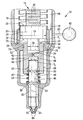
- the single FIGURE shows a cross section through the inventively proposed fuel injector.
- a fuel injector 10 includes an injector body 12 in which a cavity 84 is formed.
- a cavity 84 opens a conduit 82 which extends between the injector body 12 of the fuel injector 10 and a high-pressure accumulation chamber 80 (common rail).
- a high-pressure accumulation chamber 80 common rail
- another high-pressure source could also be used to supply the cavity 84 of the fuel injector 10 with fuel under high pressure.
- the actuator 14 is received within the cavity 84 in the upper region of the fuel injector 10.
- the actuator 14 is preferably a piezoactuator comprising a number of piezocrystals stacked one above the other.
- the actuator 14 is connected via a not-shown in the drawing electrical connection with a voltage source in connection.
- the individual piezocrystals of a piezocrystal stack lengthen; upon the termination of the application of a voltage to the piezocrystal stack of the actuator 14, the piezocrystal stack returns to its original length.
- the piezocrystal stack is indicated in the drawing by reference numeral 16.
- the piezocrystal stack 16 of the actuator 14 is enclosed by a spring 18 designed as an annular spring. Both the spring 18 and the piezocrystal stack 16 rest on an end face 22 of a step-shaped piston 20.
- step-shaped piston 20 is enclosed by a control chamber sleeve 26.
- a control chamber sleeve 26 At the control chamber sleeve 26 is a biting edge 28, with which the acted upon by a spring control chamber sleeve 26 is employed on a plane surface 72 of the injector body 12.
- the step-shaped piston 20 includes a first portion formed in a first diameter 74 and a second portion formed in a second diameter 76.
- the first diameter 74 is sized larger than the second diameter 76. Due to the difference in diameter, in which the two sections of the step-shaped piston 20 are dimensioned, formed within the control chamber sleeve 26 surrounding the step-shaped piston 20, a first hydraulic space 24. By this is a first end face 38 of a control piston 36 acted upon.
- annular surface designated by reference numeral 32 forms on the step-shaped piston 20 and delimits the first hydraulic space 24, which moreover defines a first end face 38 through the inner circumferential surface of the control chamber sleeve 26 of the control piston 36 and parts of the flat surface 72 of the injector body 12 is limited.
- the area of the step-shaped piston 20 formed in the second diameter 76 acts on a second hydraulic space 34 formed in the control piston 36.
- the second hydraulic chamber 34 is hydraulically connected to a third hydraulic chamber 66 within the control piston 36 via a duct containing a restriction 42.
- a nozzle needle injection valve member 46 In the third hydraulic chamber 66 protrudes an end face 44 of a preferably designed as a nozzle needle injection valve member 46.
- the injection valve member designed as a nozzle needle 46 is guided in the control piston 36.
- a cavity 52 In the control piston 36, a cavity 52 is formed, within which a mechanical driver 50 is able to move.
- the mechanical driver 50 may be formed, for example, as a ring or disc, which is taken in an annular groove 48 on the circumference of the formable as a nozzle needle injection valve member 46.
- the mechanical driver 50 abuts against a stop limiting the cavity 52.
- the mechanical driver 50 is held in that on a second end face 40 of the control piston 36, a spring 54 is received, which is supported on a provided in a groove 58 support disk 56 on the outer circumference of the formable as a nozzle needle injection valve member 46 and as a nozzle needle can be formed injection valve member 46 relative to the control piston 36 positioned.
- a first end face 38 of the control piston 36 can be acted upon by the first hydraulic chamber 24.
- the control piston 36 is accommodated in a further cavity in the interior of the injector body 12, in which fuel from the cavity 84 via a high-pressure inlet 30 occurs.
- the pressure level within the cavity 84, the first hydraulic chamber 24 and the cavity surrounding the control piston 36 is indicated by p 1 .
- the pressure prevailing in each case in the second hydraulic chamber 34 is designated by p 2
- the pressure prevailing in the third hydraulic chamber 66 is denoted by p 3 .
- the injection valve member 46 which can be embodied as a nozzle needle are flattenings 60, via which the in the cavity, the Control piston 36 surrounds contained fuel of a nozzle tip 62 flows and can be injected via injection openings, not shown in the combustion chamber of an internal combustion engine, if the injection openings are released through the nozzle tip 62 of the injector valve 46 can be formed as a nozzle needle.
- the nozzle tip 62 is located in a nozzle seat 64, so that the injection of fuel into the combustion chamber of the internal combustion engine is prevented.
- the control piston 36 has a jacket surface 68 surrounded by fuel and is guided in a guide 70 which is formed in the injector body 12. With reference numeral 78, the fuel flow is shown, which forms from the cavity 84, in which the actuator 14 is received, via the high-pressure inlet 30 into the cavity in which the control piston 36 is movably guided.
- the mode of operation of the fuel injector proposed according to the invention is as follows:
- the injection valve member 46 With inverse control of the actuator 14, the injection valve member 46 is in its closed position when the actuator 14 is energized.
- the actuator 14 which is preferably designed as a piezoactuator, is connected to a voltage source so that the piezocrystal stack 16 lengthens according to the number of piezocrystals present in the piezoelectric actuator and can be formed in steps Piston 20 is pressurized.
- the fuel volume present in the first hydraulic chamber 24 is compressed and the first end face 38 of the control piston 36 is acted upon.
- the pressure in the third hydraulic chamber 66 also increases, so that the control piston 36 and the injection valve member 46 guided therein are seated in the nozzle seat 64. Fuel injection does not take place.
- the opening of the preferably designed as a nozzle needle injection valve member 46 is carried out by canceling the voltage application of the actuator 14.
- the individual piezocrystals within the piezocrystal stack 16 take on cancellation of the voltage application of the actuator 14 back to its original shape, that is, the step-shaped piston 20 moves upward , whereby a pressure relief of the first hydraulic Room 24 is caused.
- the control piston 36 moves with its first end face 38 into the first hydraulic chamber 24.
- the mechanical driver 50 accommodated on the circumference of the injection valve member 46 bears against the lower stop of the cavity 52.
- the injection valve member 46 that can be formed as a nozzle needle is pulled upwards by the mechanical driver 50 enclosed by the control piston 36 and the nozzle tip 62 of the injection valve member 46 that can be embodied as a nozzle needle is moved out of its nozzle seat 64, so that the injection openings at the combustion chamber end of the fuel injector 10 - not shown in the drawing - are released and an injection of fuel into the combustion chamber.
- opening the nozzle seat 64 that is, a vertical movement of the injection valve member 46 can be formed as a nozzle needle from the nozzle seat 64 during upward movement of the control piston 36, beyond the second hydraulic chamber 34 is depressurized.
- the length of the relative movement which is between the control piston 36 and the injection valve member 46 which can preferably be embodied as a nozzle needle, depends on the extent of the cavity 52 in the axial direction of the injection valve member 46. Due to the stroke, which is able to perform the locked on the injection valve member 46 mechanical driver 50 in the cavity 52, a relative movement of the injector preferably designed as a nozzle needle 46 relative to the control piston 36 when opening is possible and an independent opening of the injection valve member 46 achievable without the actuator 14 continues to move.
- the delay of the pressure reduction in the third hydraulic chamber 66 can be adjusted.
- the inventively proposed solution can be achieved that when opening the injection valve member 46 can be formed as a nozzle opening on the one hand by the pressure reduction in the first hydraulic chamber 24 and by retraction of the control piston 36 in this takes place, due to the mechanical driver 50, the injection valve member 46 is pulled upwardly by the control piston 36 and the delayed pressure reduction in the third hydraulic chamber 66, the opening behavior of the fuel injector of the injection valve member 46 can be optimally adapted to the load state of Verbrennungskraflxnaschine.
- the resulting from the drawing structure of the fuel injector 10 captivates by its simplicity, since the preferably designed as a nozzle needle injection valve member 46 and the step-shaped piston 20 are guided in one and the same control piston 36.
- the control piston 36 in turn is guided with its lateral surface 68 in a guide 70 of the injector 12 and centered.
- the filling of the first hydraulic chamber 24 within the fuel injector 10 via gap flows between the control chamber sleeve 26 and the step-shaped piston 20, since the cavity 84, in which said components are received, is acted upon by high-pressure fuel.
- the control piston 36 is guided through the guide surface 70 within the injector body 12 of the fuel injector 10.
- the second hydraulic chamber 34 and the third hydraulic chamber 66 it should be noted that they are filled via the cavity formed in the lower region of the fuel injector 10, which flows high-pressure fuel in the direction of the arrow 78 from the cavity 84.
- the hydraulic chambers 34 and 66 are supplied with fuel via the gaps between the injection valve member 46 and the control piston 36 and the channel containing the throttle body 42.
- the spring element 54 which extends between the second end face 40 of the control piston 36 and the support plate 56 of the injection valve member 46, an initial position of the relatively movable components 36 and 46 is defined.
- the spring element 54 of the circumference of the injector valve 46 can be formed as a nozzle needle mounted mechanical driver 50 is always placed on the lower stop of the cavity 52 within the control piston 36. Since the hydraulically effective area according to the second diameter 76 of the step-shaped piston 20 is dimensioned smaller than the hydraulically effective area of the stepped piston 20, ie, the inner annular surface 32 of the step-shaped piston 20 corresponding to the first diameter 74 and the second diameter 76 leads First, the control piston 36 from an opening movement and takes the injection valve member 46 via the mechanical driver 50 with.
Claims (10)
- Injecteur de carburant muni d'un corps d'injecteur (12), avec une amenée de carburant (30) qui est en liaison avec une source de carburant haute pression (80) en dehors du corps d'injecteur (12), avec un actionneur (14) qui est reçu dans une cavité (84), depuis laquelle une amenée haute pression (30) s'étend jusqu'à un organe de soupape d'injection (46) et en fonction de la pression dans un premier espace hydraulique (24), du carburant est injecté dans une chambre de combustion d'un moteur à combustion interne, quand l'organe de soupape d'injection (46) se soulève d'un siège (64), l'actionneur (14) sollicitant directement un piston (20) limitant le premier espace hydraulique (24), réalisé sous forme étagée, qui actionne un piston de commande (36) dans lequel l'organe de soupape d'injection (46) est guidé, le piston (20) réalisé sous forme étagée étant réalisé dans avec un premier diamètre (74) et un deuxième diamètre (76), et le premier diamètre (74) étant supérieur au deuxième diamètre (76), caractérisé en ce que la différence de diamètre entre le premier diamètre (74) et le deuxième diamètre (76) constitue une surface annulaire (32) qui limite le premier espace hydraulique (24), en ce que le piston de commande (36) est guidé dans un guide (70) du corps d'injecteur (12) et présente un deuxième espace hydraulique (34) ainsi qu'un troisième espace hydraulique (66), qui sont connectés hydrauliquement l'un à l'autre, et en ce que le deuxième diamètre (76) du piston (20) réalisé sous forme étagée sollicite le deuxième espace hydraulique (34).
- Injecteur de carburant selon la revendication 1, caractérisé en ce que le premier espace hydraulique (24) est en outre entouré par une douille (26).
- Injecteur de carburant selon la revendication 1, caractérisé en ce qu'un dispositif d'entraînement mécanique (50) est disposé sur l'organe de soupape d'injection (46), lequel est guidé de manière déplaçable dans une cavité (52) du piston de commande (36) entre une première et une deuxième butée de fin de course.
- Injecteur de carburant selon la revendication 1, caractérisé en ce qu'un élément de ressort (54) est disposé entre un deuxième côté frontal (40) du piston de commande (36) et l'organe de soupape d'injection (46), lequel élément de ressort amène l'organe de soupape d'injection (46) dans une position de départ définie par rapport au piston de commande (36).
- Injecteur de carburant selon la revendication 1, caractérisé en ce que dans le cas d'une sollicitation en tension de l'actionneur (14), par sollicitation en pression simultanée du premier espace hydraulique (24) et du deuxième espace hydraulique (34) par le biais du piston (20) réalisé sous forme étagée, l'organe de soupape d'injection (46) guidé dans le piston de commande (36) est pressé dans son siège (64).
- Injecteur de carburant selon les revendications 4 et 5, caractérisé en ce qu'à la fin de la sollicitation en tension de l'actionneur (14), le premier et le deuxième espace hydraulique (24, 34) sont simultanément détendus en pression et le troisième espace hydraulique (66) est détendu en pression de manière retardée, le piston de commande (36) venant en prise autour d'un dispositif d'entraînement mécanique (50) et déplaçant l'organe de soupape d'injection (46) hors de son siège (64).
- Injecteur de carburant selon la revendication 6, caractérisé en ce que dans le cas d'une détente de pression retardée du troisième espace hydraulique (66), l'organe de soupape d'injection (46) est ouvert automatiquement davantage en fonction de l'étendue d'une cavité (52) dans le piston de commande (36) dans lequel est guidé le dispositif d'entraînement mécanique (50).
- Injecteur de carburant selon la revendication 1, caractérisé en ce que le premier espace hydraulique (24) et le deuxième espace hydraulique (34) sont connectés l'un à l'autre par le biais d'un canal contenant un point d'étranglement (42).
- Injecteur de carburant selon la revendication 2, caractérisé en ce que l'on réalise sur le corps d'injecteur (12) une surface plane (72) sur laquelle s'appuie, par une arête d'attaque (28), la douille (26) entourant le piston (20) réalisé sous forme étagée.
- Injecteur de carburant selon l'une quelconque ou plusieurs des revendications précédentes, caractérisé en ce que l'ouverture de l'organe de soupape d'injection (46) lors de la suppression de la sollicitation en tension de l'actionneur (14) s'effectue par la détente de pression du premier espace hydraulique (24), lors de l'entraînement de l'organe de soupape d'injection (46) par le piston de commande (36) et par la détente de pression retardée du troisième espace hydraulique (66) dans le piston de commande (36), tandis que l'organe de soupape d'injection (46) se déplace automatiquement par rapport au piston de commande (36) dans la direction d'ouverture.
Applications Claiming Priority (2)
| Application Number | Priority Date | Filing Date | Title |
|---|---|---|---|
| DE102004062006A DE102004062006A1 (de) | 2004-12-23 | 2004-12-23 | Kraftstoffinjektor mit direkt angesteuertem Einspritzventilglied |
| PCT/EP2005/056185 WO2006069865A1 (fr) | 2004-12-23 | 2005-11-24 | Injecteur de carburant dote d'un obturateur a commande directe |
Publications (2)
| Publication Number | Publication Date |
|---|---|
| EP1831540A1 EP1831540A1 (fr) | 2007-09-12 |
| EP1831540B1 true EP1831540B1 (fr) | 2010-10-13 |
Family
ID=36046886
Family Applications (1)
| Application Number | Title | Priority Date | Filing Date |
|---|---|---|---|
| EP05826446A Expired - Fee Related EP1831540B1 (fr) | 2004-12-23 | 2005-11-24 | Injecteur de carburant dote d'un obturateur a commande directe |
Country Status (4)
| Country | Link |
|---|---|
| US (1) | US7850091B2 (fr) |
| EP (1) | EP1831540B1 (fr) |
| DE (2) | DE102004062006A1 (fr) |
| WO (1) | WO2006069865A1 (fr) |
Families Citing this family (16)
| Publication number | Priority date | Publication date | Assignee | Title |
|---|---|---|---|---|
| DE102005007543A1 (de) | 2005-02-18 | 2006-08-24 | Robert Bosch Gmbh | Kraftstoffinjektor mit direkter Nadelsteuerung für eine Brennkraftmaschine |
| DE102006027327B4 (de) | 2006-06-13 | 2018-08-02 | Robert Bosch Gmbh | Kraftstoffinjektor mit direkter Nadelsteuerung |
| DE102007001363A1 (de) * | 2007-01-09 | 2008-07-10 | Robert Bosch Gmbh | Injektor zum Einspritzen von Kraftstoff in Brennräume von Brennkraftmaschinen |
| US8074625B2 (en) | 2008-01-07 | 2011-12-13 | Mcalister Technologies, Llc | Fuel injector actuator assemblies and associated methods of use and manufacture |
| DE102009024596A1 (de) * | 2009-06-10 | 2011-04-07 | Continental Automotive Gmbh | Einspritzventil mit Übertragungseinheit |
| DE102009024595A1 (de) | 2009-06-10 | 2011-03-24 | Continental Automotive Gmbh | Einspritzventil mit Übertragungseinheit |
| EP2674608B1 (fr) * | 2012-06-13 | 2015-08-12 | Delphi International Operations Luxembourg S.à r.l. | Injecteur à carburant |
| DE102012212264B4 (de) | 2012-07-13 | 2014-02-13 | Continental Automotive Gmbh | Verfahren zum Herstellen eines Festkörperaktuators |
| DE102012212266B4 (de) * | 2012-07-13 | 2015-01-22 | Continental Automotive Gmbh | Fluidinjektor |
| WO2014144807A1 (fr) * | 2012-11-12 | 2014-09-18 | Mcalister Technologies, Llc | Systèmes et procédés permettant une compensation et une amplification de mouvement par déplacement de fluide |
| US9309846B2 (en) | 2012-11-12 | 2016-04-12 | Mcalister Technologies, Llc | Motion modifiers for fuel injection systems |
| US9091238B2 (en) | 2012-11-12 | 2015-07-28 | Advanced Green Technologies, Llc | Systems and methods for providing motion amplification and compensation by fluid displacement |
| US9803555B2 (en) * | 2014-04-23 | 2017-10-31 | General Electric Company | Fuel delivery system with moveably attached fuel tube |
| US9562497B2 (en) * | 2014-06-18 | 2017-02-07 | Caterpillar Inc. | Engine system having piezo actuated gas injector |
| DE102016220326A1 (de) | 2016-10-18 | 2018-04-19 | Robert Bosch Gmbh | Ventil zum Zumessen eines gasförmigen oder flüssigen Kraftstoffs |
| CZ2020569A3 (cs) * | 2020-10-20 | 2021-06-16 | MOTORPAL, a.s. | Aktuátor pro řízení dávky paliva |
Citations (1)
| Publication number | Priority date | Publication date | Assignee | Title |
|---|---|---|---|---|
| WO2006008201A1 (fr) * | 2004-07-21 | 2006-01-26 | Robert Bosch Gmbh | Injecteur de carburant comportant un multiplicateur a deux etages |
Family Cites Families (15)
| Publication number | Priority date | Publication date | Assignee | Title |
|---|---|---|---|---|
| US4544096A (en) * | 1983-07-28 | 1985-10-01 | Energy Conservation Innovations, Inc. | Electronically controlled fuel injection system for diesel engine |
| JPH01187363A (ja) | 1988-01-21 | 1989-07-26 | Toyota Motor Corp | 内燃機関用燃料噴射弁 |
| DE19500706C2 (de) * | 1995-01-12 | 2003-09-25 | Bosch Gmbh Robert | Zumeßventil zur Dosierung von Flüssigkeiten oder Gasen |
| DE19743668A1 (de) * | 1997-10-02 | 1999-04-08 | Bosch Gmbh Robert | Ventil zum Steuern von Flüssigkeiten |
| DE19949527A1 (de) * | 1999-10-14 | 2001-04-19 | Bosch Gmbh Robert | Injektor für ein Kraftstoffeinspritzsystem für Brennkraftmaschinen mit in den Ventilsteuerraum ragender Düsennadel |
| US6584958B2 (en) | 1999-10-15 | 2003-07-01 | Westport Research Inc. | Directly actuated injection valve with a ferromagnetic needle |
| US6564777B2 (en) | 1999-10-15 | 2003-05-20 | Westport Research Inc. | Directly actuated injection valve with a composite needle |
| US6575138B2 (en) | 1999-10-15 | 2003-06-10 | Westport Research Inc. | Directly actuated injection valve |
| US6298829B1 (en) | 1999-10-15 | 2001-10-09 | Westport Research Inc. | Directly actuated injection valve |
| DE19954802A1 (de) * | 1999-11-13 | 2001-05-17 | Bosch Gmbh Robert | Brennstoffeinspritzventil |
| DE19956510A1 (de) * | 1999-11-25 | 2001-05-31 | Bosch Gmbh Robert | Kraftstoffeinspritzventil für Brennkraftmaschinen |
| DE10151688A1 (de) | 2001-10-19 | 2003-04-30 | Bosch Gmbh Robert | Ventil zum Steuern von Flüssigkeiten |
| DE102004005456A1 (de) * | 2004-02-04 | 2005-08-25 | Robert Bosch Gmbh | Kraftstoffinjektor mit direktgesteuertem Einspritzventilglied |
| US7100577B2 (en) * | 2004-06-14 | 2006-09-05 | Westport Research Inc. | Common rail directly actuated fuel injection valve with a pressurized hydraulic transmission device and a method of operating same |
| DE102004037125A1 (de) | 2004-07-30 | 2006-03-23 | Robert Bosch Gmbh | Common-Rail-Injektor |
-
2004
- 2004-12-23 DE DE102004062006A patent/DE102004062006A1/de not_active Withdrawn
-
2005
- 2005-11-24 US US11/721,982 patent/US7850091B2/en not_active Expired - Fee Related
- 2005-11-24 EP EP05826446A patent/EP1831540B1/fr not_active Expired - Fee Related
- 2005-11-24 WO PCT/EP2005/056185 patent/WO2006069865A1/fr active Application Filing
- 2005-11-24 DE DE502005010399T patent/DE502005010399D1/de active Active
Patent Citations (1)
| Publication number | Priority date | Publication date | Assignee | Title |
|---|---|---|---|---|
| WO2006008201A1 (fr) * | 2004-07-21 | 2006-01-26 | Robert Bosch Gmbh | Injecteur de carburant comportant un multiplicateur a deux etages |
Also Published As
| Publication number | Publication date |
|---|---|
| EP1831540A1 (fr) | 2007-09-12 |
| US7850091B2 (en) | 2010-12-14 |
| DE102004062006A1 (de) | 2006-07-13 |
| DE502005010399D1 (de) | 2010-11-25 |
| WO2006069865A1 (fr) | 2006-07-06 |
| US20090266921A1 (en) | 2009-10-29 |
Similar Documents
| Publication | Publication Date | Title |
|---|---|---|
| EP1831540B1 (fr) | Injecteur de carburant dote d'un obturateur a commande directe | |
| EP1771651B1 (fr) | Injecteur de carburant a commande polyetagee directe de l'element de soupape d'injection | |
| EP1831539B1 (fr) | Injecteur de carburant avec commande directe de l'element d'injecteur | |
| EP1756415B1 (fr) | Injecteur de carburant a multiplication d'actionneur variable | |
| EP1226354A2 (fr) | Dispositif de commande hydraulique, en particulier pour un injecteur | |
| EP1865192B1 (fr) | Injecteur de carburant doté d'une assistance adaptative à la direction | |
| WO2008049699A1 (fr) | Injecteur de carburant | |
| EP1558843B1 (fr) | Systeme d'injection de carburant pour moteurs a combustion interne | |
| EP1872008B1 (fr) | Injecteur de carburant s'ouvrant a deux niveaux | |
| EP1682769B1 (fr) | Injecteur de carburant dote d'un element de soupape d'injection en plusieurs parties, en commande directe | |
| DE102008001907A1 (de) | Kraftstoff-Injektor | |
| WO2003067070A1 (fr) | Dispositif d'injection de carburant pour un moteur a combustion interne | |
| EP1559908B1 (fr) | Injecteur de carburant pour système à rampe commune avec amplificateur hydraulique de pression intégré | |
| WO2001031191A2 (fr) | Soupape d'injection de carburant pour moteurs a combustion interne | |
| WO2003054375A1 (fr) | Dispositif d'injection de carburant pour moteur a combustion interne | |
| EP1908953B1 (fr) | Dispositif d'injection de carburant | |
| EP1377745B1 (fr) | Procede pour actionner une unite pompe-ajutage et unite pompe-ajutage correspondante | |
| DE102007009167A1 (de) | Mehrwegeventil | |
| DE19946842C2 (de) | Hochdruckpumpe | |
| DE102006013704A1 (de) | Kraftstoffinjektor mit dynamischem Kraftstoffausgleich | |
| EP2930345B1 (fr) | Injecteur de carburant | |
| WO2003069154A1 (fr) | Systeme d'injection de carburant pour un moteur a combustion interne | |
| EP1601870A1 (fr) | Soupape d'injection de carburant pour un moteur a combustion interne | |
| EP1436498A1 (fr) | Injecteur de carburant a chambre de commande a resistance a la haute pression optimisee | |
| WO2005052353A1 (fr) | Injecteur de carburant conçu pour un systeme d'injection a accumulation |
Legal Events
| Date | Code | Title | Description |
|---|---|---|---|
| PUAI | Public reference made under article 153(3) epc to a published international application that has entered the european phase |
Free format text: ORIGINAL CODE: 0009012 |
|
| 17P | Request for examination filed |
Effective date: 20070723 |
|
| AK | Designated contracting states |
Kind code of ref document: A1 Designated state(s): DE FR GB IT |
|
| DAX | Request for extension of the european patent (deleted) | ||
| RBV | Designated contracting states (corrected) |
Designated state(s): DE FR GB IT |
|
| 17Q | First examination report despatched |
Effective date: 20090729 |
|
| GRAP | Despatch of communication of intention to grant a patent |
Free format text: ORIGINAL CODE: EPIDOSNIGR1 |
|
| GRAS | Grant fee paid |
Free format text: ORIGINAL CODE: EPIDOSNIGR3 |
|
| GRAA | (expected) grant |
Free format text: ORIGINAL CODE: 0009210 |
|
| AK | Designated contracting states |
Kind code of ref document: B1 Designated state(s): DE FR GB IT |
|
| REG | Reference to a national code |
Ref country code: GB Ref legal event code: FG4D Free format text: NOT ENGLISH |
|
| REF | Corresponds to: |
Ref document number: 502005010399 Country of ref document: DE Date of ref document: 20101125 Kind code of ref document: P |
|
| PLBE | No opposition filed within time limit |
Free format text: ORIGINAL CODE: 0009261 |
|
| STAA | Information on the status of an ep patent application or granted ep patent |
Free format text: STATUS: NO OPPOSITION FILED WITHIN TIME LIMIT |
|
| 26N | No opposition filed |
Effective date: 20110714 |
|
| GBPC | Gb: european patent ceased through non-payment of renewal fee |
Effective date: 20110113 |
|
| REG | Reference to a national code |
Ref country code: DE Ref legal event code: R097 Ref document number: 502005010399 Country of ref document: DE Effective date: 20110714 |
|
| PG25 | Lapsed in a contracting state [announced via postgrant information from national office to epo] |
Ref country code: GB Free format text: LAPSE BECAUSE OF NON-PAYMENT OF DUE FEES Effective date: 20110113 |
|
| REG | Reference to a national code |
Ref country code: FR Ref legal event code: PLFP Year of fee payment: 11 |
|
| REG | Reference to a national code |
Ref country code: FR Ref legal event code: PLFP Year of fee payment: 12 |
|
| REG | Reference to a national code |
Ref country code: FR Ref legal event code: PLFP Year of fee payment: 13 |
|
| PGFP | Annual fee paid to national office [announced via postgrant information from national office to epo] |
Ref country code: FR Payment date: 20171124 Year of fee payment: 13 |
|
| PGFP | Annual fee paid to national office [announced via postgrant information from national office to epo] |
Ref country code: DE Payment date: 20190124 Year of fee payment: 14 |
|
| PG25 | Lapsed in a contracting state [announced via postgrant information from national office to epo] |
Ref country code: FR Free format text: LAPSE BECAUSE OF NON-PAYMENT OF DUE FEES Effective date: 20181130 |
|
| PGFP | Annual fee paid to national office [announced via postgrant information from national office to epo] |
Ref country code: IT Payment date: 20191120 Year of fee payment: 15 |
|
| REG | Reference to a national code |
Ref country code: DE Ref legal event code: R119 Ref document number: 502005010399 Country of ref document: DE |
|
| PG25 | Lapsed in a contracting state [announced via postgrant information from national office to epo] |
Ref country code: DE Free format text: LAPSE BECAUSE OF NON-PAYMENT OF DUE FEES Effective date: 20200603 |
|
| PG25 | Lapsed in a contracting state [announced via postgrant information from national office to epo] |
Ref country code: IT Free format text: LAPSE BECAUSE OF NON-PAYMENT OF DUE FEES Effective date: 20201124 |