EP1831540B1 - Fuel injector comprising a directly triggered injection valve member - Google Patents
Fuel injector comprising a directly triggered injection valve member Download PDFInfo
- Publication number
- EP1831540B1 EP1831540B1 EP05826446A EP05826446A EP1831540B1 EP 1831540 B1 EP1831540 B1 EP 1831540B1 EP 05826446 A EP05826446 A EP 05826446A EP 05826446 A EP05826446 A EP 05826446A EP 1831540 B1 EP1831540 B1 EP 1831540B1
- Authority
- EP
- European Patent Office
- Prior art keywords
- valve member
- injection valve
- hydraulic chamber
- control piston
- pressure
- Prior art date
- Legal status (The legal status is an assumption and is not a legal conclusion. Google has not performed a legal analysis and makes no representation as to the accuracy of the status listed.)
- Expired - Fee Related
Links
- 238000002347 injection Methods 0.000 title claims description 66
- 239000007924 injection Substances 0.000 title claims description 66
- 239000000446 fuel Substances 0.000 title claims description 56
- 230000001960 triggered effect Effects 0.000 title 1
- 238000002485 combustion reaction Methods 0.000 claims description 19
- 230000003111 delayed effect Effects 0.000 claims description 8
- 230000000694 effects Effects 0.000 description 4
- 238000009825 accumulation Methods 0.000 description 3
- 230000006835 compression Effects 0.000 description 2
- 238000007906 compression Methods 0.000 description 2
- 239000000243 solution Substances 0.000 description 2
- 230000004913 activation Effects 0.000 description 1
- 238000004891 communication Methods 0.000 description 1
- 239000013078 crystal Substances 0.000 description 1
- 230000006837 decompression Effects 0.000 description 1
- 238000000034 method Methods 0.000 description 1
- 230000007704 transition Effects 0.000 description 1
Images
Classifications
-
- F—MECHANICAL ENGINEERING; LIGHTING; HEATING; WEAPONS; BLASTING
- F02—COMBUSTION ENGINES; HOT-GAS OR COMBUSTION-PRODUCT ENGINE PLANTS
- F02M—SUPPLYING COMBUSTION ENGINES IN GENERAL WITH COMBUSTIBLE MIXTURES OR CONSTITUENTS THEREOF
- F02M51/00—Fuel-injection apparatus characterised by being operated electrically
- F02M51/06—Injectors peculiar thereto with means directly operating the valve needle
- F02M51/0603—Injectors peculiar thereto with means directly operating the valve needle using piezoelectric or magnetostrictive operating means
-
- F—MECHANICAL ENGINEERING; LIGHTING; HEATING; WEAPONS; BLASTING
- F02—COMBUSTION ENGINES; HOT-GAS OR COMBUSTION-PRODUCT ENGINE PLANTS
- F02M—SUPPLYING COMBUSTION ENGINES IN GENERAL WITH COMBUSTIBLE MIXTURES OR CONSTITUENTS THEREOF
- F02M63/00—Other fuel-injection apparatus having pertinent characteristics not provided for in groups F02M39/00 - F02M57/00 or F02M67/00; Details, component parts, or accessories of fuel-injection apparatus, not provided for in, or of interest apart from, the apparatus of groups F02M39/00 - F02M61/00 or F02M67/00; Combination of fuel pump with other devices, e.g. lubricating oil pump
- F02M63/0012—Valves
- F02M63/0031—Valves characterized by the type of valves, e.g. special valve member details, valve seat details, valve housing details
- F02M63/004—Sliding valves, e.g. spool valves, i.e. whereby the closing member has a sliding movement along a seat for opening and closing
-
- F—MECHANICAL ENGINEERING; LIGHTING; HEATING; WEAPONS; BLASTING
- F02—COMBUSTION ENGINES; HOT-GAS OR COMBUSTION-PRODUCT ENGINE PLANTS
- F02M—SUPPLYING COMBUSTION ENGINES IN GENERAL WITH COMBUSTIBLE MIXTURES OR CONSTITUENTS THEREOF
- F02M63/00—Other fuel-injection apparatus having pertinent characteristics not provided for in groups F02M39/00 - F02M57/00 or F02M67/00; Details, component parts, or accessories of fuel-injection apparatus, not provided for in, or of interest apart from, the apparatus of groups F02M39/00 - F02M61/00 or F02M67/00; Combination of fuel pump with other devices, e.g. lubricating oil pump
- F02M63/0012—Valves
- F02M63/0059—Arrangements of valve actuators
- F02M63/0061—Single actuator acting on two or more valve bodies
-
- F—MECHANICAL ENGINEERING; LIGHTING; HEATING; WEAPONS; BLASTING
- F02—COMBUSTION ENGINES; HOT-GAS OR COMBUSTION-PRODUCT ENGINE PLANTS
- F02M—SUPPLYING COMBUSTION ENGINES IN GENERAL WITH COMBUSTIBLE MIXTURES OR CONSTITUENTS THEREOF
- F02M2200/00—Details of fuel-injection apparatus, not otherwise provided for
- F02M2200/46—Valves, e.g. injectors, with concentric valve bodies
-
- F—MECHANICAL ENGINEERING; LIGHTING; HEATING; WEAPONS; BLASTING
- F02—COMBUSTION ENGINES; HOT-GAS OR COMBUSTION-PRODUCT ENGINE PLANTS
- F02M—SUPPLYING COMBUSTION ENGINES IN GENERAL WITH COMBUSTIBLE MIXTURES OR CONSTITUENTS THEREOF
- F02M2200/00—Details of fuel-injection apparatus, not otherwise provided for
- F02M2200/70—Linkage between actuator and actuated element, e.g. between piezoelectric actuator and needle valve or pump plunger
- F02M2200/703—Linkage between actuator and actuated element, e.g. between piezoelectric actuator and needle valve or pump plunger hydraulic
Definitions
- Fuel injectors with which highly pressurized fuel is injected into the combustion chambers of the internal combustion engine.
- Such fuel injectors used, for example, in auto-ignition internal combustion engines include an injector housing communicating with a high-pressure source located outside the fuel injector, such as a high-pressure common rail.
- the high-pressure accumulator in turn is supplied via a high pressure pump with high pressure fuel.
- a fuel injector with a directly controlled nozzle needle, in which the nozzle needle is driven inwards with a pressing stroke, is off WO 2006/008201 A1 or off EP 0 324 905 A known.
- a first booster piston, a second booster piston and a Düssennadelkolben is exposed in each case with an annular surface a common control chamber, so that in a pressing stroke of the piezoelectric actuator, the pressure in the control chamber increases and thereby the second booster piston and the nozzle needle piston is moved out of the control room , Due to the different diameters of the second booster piston and the nozzle needle piston is a two-stage translation of the opening stroke of the nozzle needle.
- the DE patent application 10 2004 037125.3 refers to a common rail injector.
- This comprises an injector housing with a fuel inlet which communicates with a central high-pressure fuel source outside the injector housing and with a pressure chamber inside the injector housing.
- a nozzle needle control chamber depending on the pressure in a nozzle needle control chamber, high-pressure fuel is injected into a combustion chamber of an internal combustion engine when a nozzle needle lifts off its seat.
- the nozzle needle control chamber communicates with an actuator pressure space, which is limited by an actuator, which is preferably a piezoelectric actuator.
- a throttle device is arranged, which allows a smaller flow from the nozzle needle control chamber into the Aktordruckraum when emptying the Düsennadel tenuraumes when filling the Düsennadel tenuraumes of Aktordruckraum in the nozzle needle control room.
- the throttle device is designed and arranged so that it develops its throttling effect only when emptying the nozzle needle control chamber and when filling the nozzle needle control chamber unfolds no throttle effect, but ensures an unimpeded passage of fuel.
- the throttle device comprises a throttle piston having a through hole, allowing throttled passage of fuel from the nozzle needle control chamber into the actuator pressure space.
- a direct control that is, a direct control of, for example, as a nozzle needle aussentbaren injection valve member.
- the inventively proposed fuel injector is characterized by a very simple and compact design.
- the opening of the injection valve member which can be embodied as a nozzle needle is very easily achieved by the use of a step-shaped piston assigned to an actuator.
- the actuator in particular a piezoelectric actuator, is accommodated in a cavity in which a line from a high-pressure accumulation chamber (common rail) opens.
- the step-shaped piston which can be acted upon directly by the actuator is enclosed on the one hand by a sleeve delimiting a first hydraulic space, on the other hand a part of the step-shaped piston is guided in a control piston.
- the step-shaped piston defines a first hydraulic space with an annular surface at the diameter transition and a second hydraulic space within the control piston with an end face formed in a smaller diameter.
- another, third hydraulic space is formed, wherein the second and the third hydraulic space via a channel containing a throttle point, are hydraulically in communication.
- a driver which is received on the circumference of the injection valve member which can be embodied as a nozzle needle, is movable.
- the injection valve member which can be embodied as a nozzle needle is positioned relative to the control piston such that the mechanical driver which can be embodied, for example, as a disk or ring always rests against a stop of the recess within the control piston.
- the actuator which is accommodated in the cavity of the fuel injector, is driven inversely.
- the injection valve member which can be embodied as a nozzle needle is in its closed state.
- the injection openings formed at the combustion chamber end of the fuel injector are closed by the injector member which can be formed as a nozzle needle and which is placed in its seat.
- To open the injection valve member of the piezoelectric actuator is switched to a de-energized state, so that the length of the piezocrystal stack of the Piezoactuator reduced. This leads to a pressure relief of the first hydraulic chamber, which in turn leads to the opening of the injection valve member.
- the opening of the nozzle needle is thus based on two effects, namely the pressure relief of the first hydraulic chamber when driving the step-shaped piston and the concomitant mounting of the injection needle designed as a nozzle valve member by the mechanical driver and by the pressure relief of the two formed in the control piston hydraulic chambers. Due to the pressure reduction in the two hydraulic chambers formed in the control piston, that is in the second and in the third hydraulic chamber, there is a delayed pressure reduction, so that the injection valve member which can be embodied as a nozzle needle lifts off from the mechanical driver and continues to open independently, without the piezoactuator being moved further got to.
- the proposed solution according to the invention is characterized by its simple structure and by the fact that the step-shaped piston both the control piston, in which the injector valve can be formed as an injection valve member is operated as well as for a pressure reduction or an increase in pressure in the two interconnected second and third hydraulic rooms provides. Since the second hydraulic space and the third hydraulic space are coupled to each other via a duct containing a throttle point, the pressure reduction in the third hydraulic space is delayed compared to the pressure reduction in the second hydraulic space, so that there is the possibility that the formable as a nozzle needle Injection valve member is able to move relative to the control piston and in particular further opens independently during the opening process, without the formable as a piezo actuator actuator must be moved on.
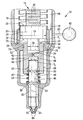
- the single FIGURE shows a cross section through the inventively proposed fuel injector.
- a fuel injector 10 includes an injector body 12 in which a cavity 84 is formed.
- a cavity 84 opens a conduit 82 which extends between the injector body 12 of the fuel injector 10 and a high-pressure accumulation chamber 80 (common rail).
- a high-pressure accumulation chamber 80 common rail
- another high-pressure source could also be used to supply the cavity 84 of the fuel injector 10 with fuel under high pressure.
- the actuator 14 is received within the cavity 84 in the upper region of the fuel injector 10.
- the actuator 14 is preferably a piezoactuator comprising a number of piezocrystals stacked one above the other.
- the actuator 14 is connected via a not-shown in the drawing electrical connection with a voltage source in connection.
- the individual piezocrystals of a piezocrystal stack lengthen; upon the termination of the application of a voltage to the piezocrystal stack of the actuator 14, the piezocrystal stack returns to its original length.
- the piezocrystal stack is indicated in the drawing by reference numeral 16.
- the piezocrystal stack 16 of the actuator 14 is enclosed by a spring 18 designed as an annular spring. Both the spring 18 and the piezocrystal stack 16 rest on an end face 22 of a step-shaped piston 20.
- step-shaped piston 20 is enclosed by a control chamber sleeve 26.
- a control chamber sleeve 26 At the control chamber sleeve 26 is a biting edge 28, with which the acted upon by a spring control chamber sleeve 26 is employed on a plane surface 72 of the injector body 12.
- the step-shaped piston 20 includes a first portion formed in a first diameter 74 and a second portion formed in a second diameter 76.
- the first diameter 74 is sized larger than the second diameter 76. Due to the difference in diameter, in which the two sections of the step-shaped piston 20 are dimensioned, formed within the control chamber sleeve 26 surrounding the step-shaped piston 20, a first hydraulic space 24. By this is a first end face 38 of a control piston 36 acted upon.
- annular surface designated by reference numeral 32 forms on the step-shaped piston 20 and delimits the first hydraulic space 24, which moreover defines a first end face 38 through the inner circumferential surface of the control chamber sleeve 26 of the control piston 36 and parts of the flat surface 72 of the injector body 12 is limited.
- the area of the step-shaped piston 20 formed in the second diameter 76 acts on a second hydraulic space 34 formed in the control piston 36.
- the second hydraulic chamber 34 is hydraulically connected to a third hydraulic chamber 66 within the control piston 36 via a duct containing a restriction 42.
- a nozzle needle injection valve member 46 In the third hydraulic chamber 66 protrudes an end face 44 of a preferably designed as a nozzle needle injection valve member 46.
- the injection valve member designed as a nozzle needle 46 is guided in the control piston 36.
- a cavity 52 In the control piston 36, a cavity 52 is formed, within which a mechanical driver 50 is able to move.
- the mechanical driver 50 may be formed, for example, as a ring or disc, which is taken in an annular groove 48 on the circumference of the formable as a nozzle needle injection valve member 46.
- the mechanical driver 50 abuts against a stop limiting the cavity 52.
- the mechanical driver 50 is held in that on a second end face 40 of the control piston 36, a spring 54 is received, which is supported on a provided in a groove 58 support disk 56 on the outer circumference of the formable as a nozzle needle injection valve member 46 and as a nozzle needle can be formed injection valve member 46 relative to the control piston 36 positioned.
- a first end face 38 of the control piston 36 can be acted upon by the first hydraulic chamber 24.
- the control piston 36 is accommodated in a further cavity in the interior of the injector body 12, in which fuel from the cavity 84 via a high-pressure inlet 30 occurs.
- the pressure level within the cavity 84, the first hydraulic chamber 24 and the cavity surrounding the control piston 36 is indicated by p 1 .
- the pressure prevailing in each case in the second hydraulic chamber 34 is designated by p 2
- the pressure prevailing in the third hydraulic chamber 66 is denoted by p 3 .
- the injection valve member 46 which can be embodied as a nozzle needle are flattenings 60, via which the in the cavity, the Control piston 36 surrounds contained fuel of a nozzle tip 62 flows and can be injected via injection openings, not shown in the combustion chamber of an internal combustion engine, if the injection openings are released through the nozzle tip 62 of the injector valve 46 can be formed as a nozzle needle.
- the nozzle tip 62 is located in a nozzle seat 64, so that the injection of fuel into the combustion chamber of the internal combustion engine is prevented.
- the control piston 36 has a jacket surface 68 surrounded by fuel and is guided in a guide 70 which is formed in the injector body 12. With reference numeral 78, the fuel flow is shown, which forms from the cavity 84, in which the actuator 14 is received, via the high-pressure inlet 30 into the cavity in which the control piston 36 is movably guided.
- the mode of operation of the fuel injector proposed according to the invention is as follows:
- the injection valve member 46 With inverse control of the actuator 14, the injection valve member 46 is in its closed position when the actuator 14 is energized.
- the actuator 14 which is preferably designed as a piezoactuator, is connected to a voltage source so that the piezocrystal stack 16 lengthens according to the number of piezocrystals present in the piezoelectric actuator and can be formed in steps Piston 20 is pressurized.
- the fuel volume present in the first hydraulic chamber 24 is compressed and the first end face 38 of the control piston 36 is acted upon.
- the pressure in the third hydraulic chamber 66 also increases, so that the control piston 36 and the injection valve member 46 guided therein are seated in the nozzle seat 64. Fuel injection does not take place.
- the opening of the preferably designed as a nozzle needle injection valve member 46 is carried out by canceling the voltage application of the actuator 14.
- the individual piezocrystals within the piezocrystal stack 16 take on cancellation of the voltage application of the actuator 14 back to its original shape, that is, the step-shaped piston 20 moves upward , whereby a pressure relief of the first hydraulic Room 24 is caused.
- the control piston 36 moves with its first end face 38 into the first hydraulic chamber 24.
- the mechanical driver 50 accommodated on the circumference of the injection valve member 46 bears against the lower stop of the cavity 52.
- the injection valve member 46 that can be formed as a nozzle needle is pulled upwards by the mechanical driver 50 enclosed by the control piston 36 and the nozzle tip 62 of the injection valve member 46 that can be embodied as a nozzle needle is moved out of its nozzle seat 64, so that the injection openings at the combustion chamber end of the fuel injector 10 - not shown in the drawing - are released and an injection of fuel into the combustion chamber.
- opening the nozzle seat 64 that is, a vertical movement of the injection valve member 46 can be formed as a nozzle needle from the nozzle seat 64 during upward movement of the control piston 36, beyond the second hydraulic chamber 34 is depressurized.
- the length of the relative movement which is between the control piston 36 and the injection valve member 46 which can preferably be embodied as a nozzle needle, depends on the extent of the cavity 52 in the axial direction of the injection valve member 46. Due to the stroke, which is able to perform the locked on the injection valve member 46 mechanical driver 50 in the cavity 52, a relative movement of the injector preferably designed as a nozzle needle 46 relative to the control piston 36 when opening is possible and an independent opening of the injection valve member 46 achievable without the actuator 14 continues to move.
- the delay of the pressure reduction in the third hydraulic chamber 66 can be adjusted.
- the inventively proposed solution can be achieved that when opening the injection valve member 46 can be formed as a nozzle opening on the one hand by the pressure reduction in the first hydraulic chamber 24 and by retraction of the control piston 36 in this takes place, due to the mechanical driver 50, the injection valve member 46 is pulled upwardly by the control piston 36 and the delayed pressure reduction in the third hydraulic chamber 66, the opening behavior of the fuel injector of the injection valve member 46 can be optimally adapted to the load state of Verbrennungskraflxnaschine.
- the resulting from the drawing structure of the fuel injector 10 captivates by its simplicity, since the preferably designed as a nozzle needle injection valve member 46 and the step-shaped piston 20 are guided in one and the same control piston 36.
- the control piston 36 in turn is guided with its lateral surface 68 in a guide 70 of the injector 12 and centered.
- the filling of the first hydraulic chamber 24 within the fuel injector 10 via gap flows between the control chamber sleeve 26 and the step-shaped piston 20, since the cavity 84, in which said components are received, is acted upon by high-pressure fuel.
- the control piston 36 is guided through the guide surface 70 within the injector body 12 of the fuel injector 10.
- the second hydraulic chamber 34 and the third hydraulic chamber 66 it should be noted that they are filled via the cavity formed in the lower region of the fuel injector 10, which flows high-pressure fuel in the direction of the arrow 78 from the cavity 84.
- the hydraulic chambers 34 and 66 are supplied with fuel via the gaps between the injection valve member 46 and the control piston 36 and the channel containing the throttle body 42.
- the spring element 54 which extends between the second end face 40 of the control piston 36 and the support plate 56 of the injection valve member 46, an initial position of the relatively movable components 36 and 46 is defined.
- the spring element 54 of the circumference of the injector valve 46 can be formed as a nozzle needle mounted mechanical driver 50 is always placed on the lower stop of the cavity 52 within the control piston 36. Since the hydraulically effective area according to the second diameter 76 of the step-shaped piston 20 is dimensioned smaller than the hydraulically effective area of the stepped piston 20, ie, the inner annular surface 32 of the step-shaped piston 20 corresponding to the first diameter 74 and the second diameter 76 leads First, the control piston 36 from an opening movement and takes the injection valve member 46 via the mechanical driver 50 with.
Description
An Verbrennungskraftmaschinen kommen Kraftstoffinjektoren zum Einsatz, mit welchen unter hohem Druck stehender Kraftstoff in die Brennräume der Verbrennungskraftmaschine eingespritzt wird. Derartige Kraftstoffinjektoren, die zum Beispiel bei selbstzündenden Verbrennungskraftmaschinen eingesetzt werden, umfassen ein Injektorgehäuse, welches mit einer außerhalb des Kraftstoffinjektors angeordneten Hochdruckquelle, wie zum Beispiel einem Hochdrucksammelraum (Common-Rail), in Verbindung steht. Der Hochdrucksammelraum seinerseits wird über eine Hochdruckpumpe mit unter hohem Druck stehenden Kraftstoff versorgt.Internal combustion engines use fuel injectors, with which highly pressurized fuel is injected into the combustion chambers of the internal combustion engine. Such fuel injectors used, for example, in auto-ignition internal combustion engines, include an injector housing communicating with a high-pressure source located outside the fuel injector, such as a high-pressure common rail. The high-pressure accumulator in turn is supplied via a high pressure pump with high pressure fuel.
Ein Kraftstoffinjektor mit einer direkt angesteuerten Düsennadel, bei dem die Düsennadel mit einem drückenden Hub nach innen öffnend angesteuert wird, ist aus
Die
das einen gedrosselten Durchtritt von Kraftstoff von dem Düsennadelsteuerraum in den Aktordruckraum ermöglicht.The
allowing throttled passage of fuel from the nozzle needle control chamber into the actuator pressure space.
Bei Kraftstoffinjektoren, bei denen der Druck in einem Steuerraum durch einen Aktor, wie zum Beispiel einen Piezoaktor, gesteuert wird spricht man auch von einer direkten Steuerung, das heißt einer direkten Steuerung des zum Beispiel als Düsennadel ausbildbaren Einspritzventilgliedes.In fuel injectors, in which the pressure in a control chamber is controlled by an actuator, such as a piezoelectric actuator, one speaks of a direct control, that is, a direct control of, for example, as a nozzle needle ausbildbaren injection valve member.
Der erfindungsgemäß vorgeschlagene Kraftstoffinjektor zeichnet sich durch einen sehr einfachen und kompakten Aufbau aus. Insbesondere wird durch den Einsatz eines einem Aktor zugeordneten stufenförmig ausgebildeten Kolbens das Öffnen des als Düsennadel ausbildbaren Einspritzventilgliedes sehr einfach erreicht.The inventively proposed fuel injector is characterized by a very simple and compact design. In particular, the opening of the injection valve member which can be embodied as a nozzle needle is very easily achieved by the use of a step-shaped piston assigned to an actuator.
Der Aktor, insbesondere ein Piezoaktor, ist in einem Hohlraum aufgenommen, in welchem eine Leitung von einem Hochdrucksammelraum (Common-Rail) mündet. Der durch den Aktor direkt beaufschlagbare stufenförmig ausgebildete Kolben ist einerseits von einer einen ersten hydraulischen Raum begrenzenden Hülse umschlossen, andererseits ist ein Teil des stufenförmig ausbildbaren Kolbens in einem Steuerkolben geführt. Der stufenförmig ausbildbare Kolben begrenzt mit einer Ringfläche am Durchmesserübergang einen ersten hydraulischen Raum und mit einer in einem geringeren Durchmesser ausgebildeten Stirnfläche einen zweiten hydraulischen Raum innerhalb des Steuerkolbens. Innerhalb des Steuerkolbens ist ein weiterer, dritter hydraulischer Raum ausgebildet, wobei der zweite und der dritte hydraulische Raum über einen Kanal, der eine Drosselstelle enthält, hydraulisch in Verbindung stehen. Im Steuerkolben befindet sich darüber hinaus eine Ausnehmung, in welcher ein Mitnehmer, der am Umfang des als Düsennadel ausbildbaren Einspritzventilgliedes aufgenommen ist, bewegbar ist. Über eine an der unteren Stirnseite des Steuerkolbens sich abstützende Druckfeder wird das als Düsennadel ausbildbare Einspritzventilglied relativ zum Steuerkolben so gestellt, dass der beispielsweise als Scheibe oder Ring ausbildbare mechanische Mitnehmer stets an einem Anschlag der Ausnehmung innerhalb des Steuerkolbens anliegt. Der Aktor, der in dem Hohlraum des Kraftstoffinjektors aufgenommen ist, wird invers angesteuert. Bei einer inversen Ansteuerung eines Piezoaktors ist dieser bestromt und das als Düsennadel ausbildbare Einspritzventilglied befindet sich in seinem geschlossenen Zustand. Die am brennraumseitigen Ende des Kraftstoffinjektors ausgebildeten Einspritzöffnungen sind durch das in seinen Sitz gestellte, als Düsennadel ausbildbare Einspritzventilglied verschlossen. Zum Öffnen des Einspritzventilglieds wird der Piezoaktor in einen stromlosen Zustand geschaltet, so dass sich die Länge des Piezokristallstapels des Piezoaktors reduziert. Dies führt zu einer Druckentlastung des ersten hydraulischen Raumes, die wiederum zum Öffnen des Einspritzventilglieds führt.The actuator, in particular a piezoelectric actuator, is accommodated in a cavity in which a line from a high-pressure accumulation chamber (common rail) opens. The step-shaped piston which can be acted upon directly by the actuator is enclosed on the one hand by a sleeve delimiting a first hydraulic space, on the other hand a part of the step-shaped piston is guided in a control piston. The step-shaped piston defines a first hydraulic space with an annular surface at the diameter transition and a second hydraulic space within the control piston with an end face formed in a smaller diameter. Within the control piston, another, third hydraulic space is formed, wherein the second and the third hydraulic space via a channel containing a throttle point, are hydraulically in communication. In addition, there is a recess in the control piston in which a driver, which is received on the circumference of the injection valve member which can be embodied as a nozzle needle, is movable. By way of a compression spring which is supported on the lower end face of the control piston, the injection valve member which can be embodied as a nozzle needle is positioned relative to the control piston such that the mechanical driver which can be embodied, for example, as a disk or ring always rests against a stop of the recess within the control piston. The actuator, which is accommodated in the cavity of the fuel injector, is driven inversely. In the case of an inverse activation of a piezoactuator, it is supplied with current and the injection valve member which can be embodied as a nozzle needle is in its closed state. The injection openings formed at the combustion chamber end of the fuel injector are closed by the injector member which can be formed as a nozzle needle and which is placed in its seat. To open the injection valve member of the piezoelectric actuator is switched to a de-energized state, so that the length of the piezocrystal stack of the Piezoactuator reduced. This leads to a pressure relief of the first hydraulic chamber, which in turn leads to the opening of the injection valve member.
Bei Druckentlastung des ersten hydraulischen Raumes fährt der Steuerkolben in diesen ein. Gleichzeitig wird durch den stufenförmig ausbildbaren Kolben der zweite hydraulische Raum innerhalb des Steuerkolbens druckentlastet, was das Öffnen des als Düsennadel ausbildbaren Einspritzventilgliedes unterstützt. Bei Druckentlastung des zweiten hydraulischen Raumes wird auch der dritte hydraulische Raum druckentlastet, da dieser mit dem zweiten hydraulischen Raum mit einem Kanal verbunden ist. Der Steuerkolben ist über den mechanischen Mitnehmer mit dem als Düsennadel ausbildbaren Einspritzventilglied verbunden, so dass bei Druckentlastung des ersten hydraulischen Raumes durch Auffahren des stufenförmig ausbildbaren Kolbens bei in den ersten hydraulischen Raum sich hineinbewegendem Steuerkolben das als Düsennadel ausbildbare Einspritzventilglied aufgezogen wird. Das Öffnen der Düsennadel beruht somit auf zwei Effekten, nämlich der Druckentlastung des ersten hydraulischen Raumes bei Auffahren des stufenförmig ausbildbaren Kolbens und das damit einhergehende Aufziehen des als Düsennadel ausbildbaren Einspritzventilgliedes durch den mechanischen Mitnehmer und durch die Druckentlastung der beiden im Steuerkolben ausgebildeten hydraulischen Räume. Aufgrund der Druckabsenkung in den beiden im Steuerkolben ausgebildeten hydraulischen Räumen, das heißt im zweiten und im dritten hydraulischen Raum, erfolgt eine verzögerte Druckabsenkung, so dass das als Düsennadel ausbildbare Einspritzventilglied vom mechanischen Mitnehmer abhebt und weiter selbstständig öffnet, ohne dass der Piezoaktor weiter bewegt werden muss.When pressure relief of the first hydraulic chamber of the control piston moves into this. At the same time, the second hydraulic space within the control piston is depressurized by the step-shaped piston, which assists in opening the injection valve member which can be embodied as a nozzle needle. When pressure relief of the second hydraulic chamber and the third hydraulic chamber is relieved of pressure, since it is connected to the second hydraulic chamber with a channel. The control piston is connected via the mechanical driver with the injection valve member which can be embodied as a nozzle needle, so that the injection valve member which can be embodied as a nozzle needle is mounted when the pressure relief of the first hydraulic chamber is started up by driving the stepped piston into the first hydraulic chamber. The opening of the nozzle needle is thus based on two effects, namely the pressure relief of the first hydraulic chamber when driving the step-shaped piston and the concomitant mounting of the injection needle designed as a nozzle valve member by the mechanical driver and by the pressure relief of the two formed in the control piston hydraulic chambers. Due to the pressure reduction in the two hydraulic chambers formed in the control piston, that is in the second and in the third hydraulic chamber, there is a delayed pressure reduction, so that the injection valve member which can be embodied as a nozzle needle lifts off from the mechanical driver and continues to open independently, without the piezoactuator being moved further got to.
Die erfindungsgemäß vorgeschlagene Lösung zeichnet sich durch ihren einfachen Aufbau aus und durch den Umstand, dass der stufenförmig ausbildbare Kolben sowohl den Steuerkolben, in den das als Düsennadel ausbildbare Einspritzventilglied geführt ist, betätigt als auch für eine Druckabsenkung beziehungsweise für einen Druckanstieg in den beiden miteinander verbundenen zweiten und dritten hydraulischen Räumen sorgt. Da der zweite hydraulische Raum und der dritte hydraulische Raum über einen eine Drosselstelle enthaltenen Kanal miteinander gekoppelt sind, erfolgt der Druckabbau im dritten hydraulischen Raum verzögert, verglichen mit dem Druckabbau im zweiten hydraulischen Raum, so dass die Möglichkeit gegeben ist, dass das als Düsennadel ausbildbare Einspritzventilglied sich relativ zum Steuerkolben zu bewegen vermag und insbesondere beim Öffnungsvorgang weiter selbständig öffnet, ohne dass der als Piezoaktor ausbildbare Aktor weiter bewegt werden muss.The proposed solution according to the invention is characterized by its simple structure and by the fact that the step-shaped piston both the control piston, in which the injector valve can be formed as an injection valve member is operated as well as for a pressure reduction or an increase in pressure in the two interconnected second and third hydraulic rooms provides. Since the second hydraulic space and the third hydraulic space are coupled to each other via a duct containing a throttle point, the pressure reduction in the third hydraulic space is delayed compared to the pressure reduction in the second hydraulic space, so that there is the possibility that the formable as a nozzle needle Injection valve member is able to move relative to the control piston and in particular further opens independently during the opening process, without the formable as a piezo actuator actuator must be moved on.
Anhand der Zeichnung wird die Erfindung nachstehend näher erläutert.Reference to the drawings, the invention will be explained in more detail below.
Die einzige Figur zeigt einen Querschnitt durch den erfindungsgemäß vorgeschlagenen Kraftstoffinjektor.The single FIGURE shows a cross section through the inventively proposed fuel injector.
Ein Kraftstoffinjektor 10 umfasst einen Injektorkörper 12, in welchem ein Hohlraum 84 ausgebildet ist. In den Hohlraum 84 mündet eine Leitung 82, die sich zwischen dem Injektorkörper 12 des Kraftstoffinjektors 10 und einem Hochdrucksammelraum 80 (Common-Rail) erstreckt. An Stelle des Hochdrucksammelraumes 80 (Common-Rail) könnte auch eine andere Hochdruckquelle eingesetzt werden, um den Hohlraum 84 des Kraftstoffinjektors 10 mit unter hohem Druck stehenden Kraftstoff zu versorgen. Innerhalb des Hohlraumes 84 im oberen Bereich des Kraftstoffinjektors 10 ist ein Aktor 14 aufgenommen. Bei dem Aktor 14 handelt es sich bevorzugt um einen Piezoaktor, der eine Anzahl von Piezokristallen umfasst, die stapelförmig übereinander angeordnet sind. Der Aktor 14 steht über eine in der Zeichnung nicht dargestellte elektrische Verbindung mit einer Spannungsquelle in Verbindung. Bei Beaufschlagung des Aktors 14 mit einer Spannung längen sich die einzelnen Piezokristalle eines Piezokristallstapels, bei Beendigung des Anlegens einer Spannung an den Piezokristallstapel des Aktors 14 nimmt der Piezokristallstapel wieder seine ursprüngliche Länge ein. Der Piezokristallstapel ist in der Zeichnung durch Bezugszeichen 16 kenntlich gemacht. Der Piezokristallstapel 16 des Aktors 14 ist von einer als Ringfeder ausgebildeten Feder 18 umschlossen. Sowohl die Feder 18 als auch der Piezokristallstapel 16 ruhen auf einer Stirnfläche 22 eines stufenförmig ausbildbaren Kolbens 20.A
Der ebenfalls im Hohlraum 84 aufgenommene, stufenförmig ausbildbare Kolben 20 ist von einer Steuerraumhülse 26 umschlossen. An der Steuerraumhülse 26 befindet sich eine Beißkante 28, mit welcher die durch eine Feder beaufschlagte Steuerraumhülse 26 an einer Planfläche 72 des Injektorkörpers 12 angestellt ist. Der stufenförmig ausbildbare Kolben 20 umfasst einen ersten Bereich, der in einem ersten Durchmesser 74 ausgebildet ist sowie einen zweiten Bereich, der in einem zweiten Durchmesser 76 ausgebildet ist. Der erste Durchmesser 74 ist größer bemessen als der zweite Durchmesser 76. Aufgrund der Durchmesserdifferenz, in der die beiden Abschnitte des stufenförmig ausbildbaren Kolbens 20 dimensioniert sind, bildet sich innerhalb der den stufenförmig ausbildbaren Kolben 20 umgebenden Steuerraumhülse 26 ein erster hydraulischer Raum 24. Durch diesen ist eine erste Stirnseite 38 eines Steuerkolbens 36 beaufschlagbar.The also embodied in the
Am stufenförmig ausbildbaren Kolben 20 bildet sich aufgrund des Durchmesserunterschiedes zwischen dem ersten Durchmesser 74 und dem zweiten Durchmesser 76 eine durch Bezugszeichen 32 bezeichnete Ringfläche aus, die den ersten hydraulischen Raum 24 begrenzt, der darüber hinaus durch die Innenumfangsfläche der Steuerraumhülse 26, eine erste Stirnseite 38 des Steuerkolbens 36 und Teile der Planfläche 72 des Injektorkörpers 12 begrenzt wird.Due to the difference in diameter between the
Der in dem zweiten Durchmesser 76 ausgebildete Bereich des stufenförmig ausbildbaren Kolbens 20 beaufschlagt einen zweiten hydraulischen Raum 34, der im Steuerkolben 36 ausgebildet ist. Der zweite hydraulische Raum 34 ist über einen eine Drosselstelle 42 enthaltenden Kanal mit einem dritten hydraulischen Raum 66 innerhalb des Steuerkolbens 36 hydraulisch verbunden.The area of the step-shaped piston 20 formed in the
In den dritten hydraulischen Raum 66 ragt eine Stirnfläche 44 eines bevorzugt als Düsennadel ausbildbaren Einspritzventilgliedes 46. Das als Düsennadel ausgebildete Einspritzventilglied 46 ist im Steuerkolben 36 geführt. Im Steuerkolben 36 ist ein Hohlraum 52 ausgebildet, innerhalb dessen sich ein mechanischer Mitnehmer 50 zu bewegen vermag. Der mechanische Mitnehmer 50 kann zum Beispiel als Ring oder als Scheibe ausgebildet werden, die in einer Ringnut 48 am Umfang des als Düsennadel ausbildbaren Einspritzventilgliedes 46 auf genommen ist.In the third
In der Darstellung gemäß der Figur liegt der mechanische Mitnehmer 50 an einem den Hohlraum 52 begrenzenden Anschlag an. In dieser Position wird der mechanische Mitnehmer 50 dadurch gehalten, dass an einer zweiten Stirnseite 40 des Steuerkolbens 36 eine Feder 54 aufgenommen ist, die sich an einer in einer Nut 58 vorgesehenen Stützscheibe 56 am Außenumfang des als Düsennadel ausbildbaren Einspritzventilgliedes 46 abstützt und das als Düsennadel ausbildbare Einspritzventilglied 46 relativ zum Steuerkolben 36 positioniert. Der Vollständigkeit halber sei erwähnt, dass eine erste Stirnseite 38 des Steuerkolbens 36 durch den ersten hydraulischen Raum 24 beaufschlagbar ist.In the illustration according to the figure, the
Der Steuerkolben 36 ist in einem weiteren Hohlraum im Inneren des Injektorkörpers 12 aufgenommen, in welchen vom Hohlraum 84 über einen Hochdruckzulauf 30 Kraftstoff eintritt. Das Druckniveau innerhalb des Hohlraumes 84, des ersten hydraulischen Raumes 24 und des den Steuerkolben 36 umschließenden Hohlraumes ist durch p1 bezeichnet. Der jeweils im zweiten hydraulischen Raum 34 herrschende Druck ist durch p2 bezeichnet, während der im dritten hydraulischen Raum 66 herrschende Druck durch p3 bezeichnet ist.The
Unterhalb der Stützscheibe 56 am Außenumfang des als Düsennadel ausbildbaren Einspritzventilgliedes 46 befinden sich Abflachungen 60, über welche der im Hohlraum, der den Steuerkolben 36 umgibt, enthaltene Kraftstoff einer Düsenspitze 62 zuströmt und über in der Zeichnung nicht dargestellte Einspritzöffnungen in den Brennraum einer Verbrennungskraftmaschine eingespritzt werden kann, falls die Einspritzöffnungen durch die Düsenspitze 62 des als Düsennadel ausbildbaren Einspritzventilgliedes 46 freigegeben sind. In der Darstellung gemäß der Figur befindet sich die Düsenspitze 62 in einem Düsensitz 64, so dass das Einspritzen von Kraftstoff in den Brennraum der Verbrennungskraftmaschine unterbunden ist.Below the
Der Steuerkolben 36 weist eine von Kraftstoff umgebene Mantelfläche 68 auf und ist in einer Führung 70, die im Injektorkörper 12 ausgebildet ist, geführt. Mit Bezugszeichen 78 ist die Kraftstoffströmung dargestellt, welche sich vom Hohlraum 84, in dem der Aktor 14 aufgenommen ist, über den Hochdruckzulauf 30 in den Hohlraum ausbildet, in dem der Steuerkolben 36 bewegbar geführt ist.The
Die Funktionsweise des erfindungsgemäß vorgeschlagenen Kraftstoffinjektors stellt sich wie folgt dar:The mode of operation of the fuel injector proposed according to the invention is as follows:
Bei inverser Ansteuerung des Aktors 14 befindet sich das Einspritzventilglied 46 in seiner Schließstellung, wenn der Aktor 14 bestromt ist.With inverse control of the
In der Darstellung gemäß der Zeichnung befindet sich das bevorzugt als Düsennadel ausbildbare Einspritzventilglied 46 in seiner Schließstellung. In diesem Zustand sind die in der Zeichnung nicht dargestellten Einspritzöffnungen in den Brennraum einer Verbrennungskraftmaschine verschlossen; die Düsenspitze 62 befindet sich im Düsensitz 64. Um das Schließen des Einspritzventilgliedes 46 zu bewirken, ist der bevorzugt als Piezoaktor ausgebildete Aktor 14 mit einer Spannungsquelle verbunden, so dass sich der Piezokristallstapel 16 entsprechend der Anzahl der in diesem vorhandenen Piezokristalle längt und der stufenförmig ausbildbare Kolben 20 druckbeaufschlagt ist. Dadurch wird das im ersten hydraulischen Raum 24 vorhandene Kraftstoffvolumen komprimiert und die erste Stirnseite 38 des Steuerkolbens 36 beaufschlagt. Weiterhin steigt aufgrund der Kompression des Kraftstoffvolumens im zweiten hydraulischen Raum 34 auch der Druck im dritten hydraulischen Raum 66, so dass der Steuerkolben 36 und das in diesem geführte Einspritzventilglied 46 in den Düsensitz 64 gestellt ist. Eine Kraftstoffeinspritzung findet nicht statt.In the illustration according to the drawing, preferably designed as a nozzle needle
Das Öffnen des bevorzugt als Düsennadel ausbildbaren Einspritzventilgliedes 46 erfolgt durch Aufhebung der Spannungsbeaufschlagung des Aktors 14. Die einzelnen Piezokristalle innerhalb des Piezokristallstapels 16 nehmen bei Aufhebung der Spannungsbeaufschlagung des Aktors 14 wieder ihre ursprüngliche Gestalt an, das heißt der stufenförmig ausbildbare Kolben 20 bewegt sich nach oben, wodurch eine Druckentlastung des ersten hydraulischen Raumes 24 hervorgerufen wird. Aufgrund der Druckentlastung des ersten hydraulischen Raumes 24 fährt der Steuerkolben 36 mit seiner ersten Stirnseite 38 in den ersten hydraulischen Raum 24 ein. Während der auf den ersten hydraulischen Raum 24 gerichteten Vertikalbewegung des Steuerkolbens 36 liegt der am Umfang des Einspritzventilgliedes 46 aufgenommene mechanische Mitnehmer 50 am unteren Anschlag des Hohlraums 52 an. Fährt der Steuerkolben 36 in vertikale Richtung nach oben, wird das als Düsennadel ausbildbare Einspritzventilglied 46 durch den vom Steuerkolben 36 umschlossenen mechanischen Mitnehmer 50 nach oben gezogen und die Düsenspitze 62 des als Düsennadel ausbildbaren Einspritzventilgliedes 46 wird aus ihrem Düsensitz 64 bewegt, so dass die Einspritzöffnungen am brennraumseitigen Ende des Kraftstoffinjektors 10 - in der Zeichnung nicht dargestellt - freigegeben werden und eine Einspritzung von Kraftstoff in den Brennraum erfolgt. Beim Öffnen des Düsensitzes 64, das heißt einer Vertikalbewegung des als Düsennadel ausbildbaren Einspritzventilgliedes 46 aus dem Düsensitz 64 bei Aufwärtsbewegung des Steuerkolbens 36, wird darüber hinaus der zweite hydraulische Raum 34 druckentlastet. Dies erfolgt dadurch, dass bei Aufhebung der Spannungsbeaufschlagung des Aktors 14 sich der im zweiten Durchmesser 76 ausgebildete Bereich des stufenförmig ausbildbaren Kolbens 20 aus dem zweiten hydraulischen Raum 34 herausbewegt. Da der zweite hydraulische Raum 34 und der dritte hydraulische Raum 66 über einen eine Drosselstelle 42 enthaltenen Kanal hydraulisch miteinander verbunden sind, stellt sich im dritten hydraulischen Raum 66 bei Druckentlastung des zweiten hydraulischen Raumes 34 ein verzögerter Druckabbau ein. Der auf diese Weise realisierte verzögerte Druckabbau im dritten hydraulischen Raum 66 hat zur Folge, dass sich das bevorzugt als Düsennadel ausbildbare Einspritzventilglied 46 relativ zum Steuerkolben 36 bewegt. In diesem Falle hebt der mechanische Mitnehmer 50 vom unteren Anschlag des Hohlraumes 52 ab. Die Länge der Relativbewegung, die sich zwischen dem Steuerkolben 36 und dem bevorzugt als Düsennadel ausbildbaren Einspritzventilgliedes 46 darstellt, hängt von der Erstreckung des Hohlraumes 52 in axialer Richtung des Einspritzventilgliedes 46 ab. Aufgrund des Hubweges, den der am Einspritzventilglied 46 arretierte mechanische Mitnehmer 50 im Hohlraum 52 auszuführen vermag, ist eine Relativbewegung des bevorzugt als Düsennadel ausbildbaren Einspritzventilgliedes 46 bezogen auf den Steuerkolben 36 beim Öffnen möglich und ein selbständiges Öffnen des Einspritzventilgliedes 46 erreichbar, ohne dass der Aktor 14 weiter zu bewegen ist.The opening of the preferably designed as a nozzle needle
Durch die jeweilige Dimensionierung der Drosselstelle 42, die im Kanal zwischen dem zweiten und dem dritten hydraulischen Raum 34, 66 vorgesehen ist, kann die Verzögerung des Druckabbaus im dritten hydraulischen Raum 66 eingestellt werden.By the respective dimensioning of the
Durch die erfindungsgemäß vorgeschlagene Lösung kann erreicht werden, dass beim Öffnen des als Düsennadel ausbildbaren Einspritzventilgliedes 46 das Öffnen einerseits durch den Druckabbau im ersten hydraulischen Raum 24 und durch Einfahren des Steuerkolbens 36 in diesen erfolgt, wobei aufgrund des mechanischen Mitnehmers 50 das Einspritzventilglied 46 durch den Steuerkolben 36 nach oben gezogen wird und des verzögerten Druckabbaus im dritten hydraulischen Raum 66 das Öffnungsverhalten des Kraftstoffinjektors des Einspritzventilgliedes 46 in optimaler Weise an den Lastzustand der Verbrennungskraflxnaschine angepasst werden kann. Der aus der Zeichnung hervorgehende Aufbau des Kraftstoffinjektors 10 besticht durch seine Einfachheit, da das bevorzugt als Düsennadel ausbildbare Einspritzventilglied 46 sowie der stufenförmig ausbildbare Kolben 20 in ein und demselben Steuerkolben 36 geführt sind. Der Steuerkolben 36 seinerseits ist mit seiner Mantelfläche 68 in einer Führung 70 des Injektorgehäuses 12 geführt und zentriert.By the inventively proposed solution can be achieved that when opening the
Die Befüllung des ersten hydraulischen Raumes 24 innerhalb des Kraftstoffinjektors 10 erfolgt über Spaltströmungen zwischen der Steuerraumhülse 26 und dem stufenförmig ausbildbaren Kolben 20, da der Hohlraum 84, in dem die genannten Komponenten aufgenommen sind, mit unter hohem Druck stehenden Kraftstoff beaufschlagt ist. Der Steuerkolben 36 ist durch die Führungsfläche 70 innerhalb des Injektorkörpers 12 des Kraftstoffinjektors 10 geführt. Hinsichtlich der Befüllung des zweiten hydraulischen Raumes 34 und des dritten hydraulischen Raumes 66 ist festzuhalten, dass deren Befüllung über den im unteren Bereich des Kraftstoffinjektors 10 ausgebildeten Hohlraum erfolgt, dem unter hohem Druck stehender Kraftstoff in Richtung des Pfeils 78 vom Hohlraum 84 aus zuströmt. Über die Spalte zwischen dem Einspritzventilglied 46 und dem Steuerkolben 36 sowie den die Drosselstelle 42 enthaltenden Kanal werden die hydraulischen Räume 34 beziehungsweise 66 mit Kraftstoff beaufschlagt.The filling of the first
Durch das Federelement 54, welches sich zwischen der zweiten Stirnseite 40 des Steuerkolbens 36 und der Stützscheibe 56 des Einspritzventilgliedes 46 erstreckt, wird eine Ausgangsposition der relativ zu einander bewegbaren Komponenten 36 und 46 definiert. Durch das Federelement 54 ist der am Umfang des als Düsennadel ausbildbaren Einspritzventilgliedes 46 angebrachte mechanische Mitnehmer 50 stets an den unteren Anschlag des Hohlraumes 52 innerhalb des Steuerkolbens 36 gestellt. Da die hydraulisch wirksame Fläche gemäß des zweiten Durchmessers 76 des stufenförmig ausbildbaren Kolbens 20 kleiner bemessen ist als die hydraulisch wirksame Fläche des stufenförmigen Kolbens 20, d.h. die innere Ringfläche 32 des stufenförmig ausbildbaren Kolbens 20 entsprechend des ersten Durchmessers 74 und des zweiten Durchmessers 76, führt zunächst der Steuerkolben 36 eine Öffnungsbewegung aus und nimmt das Einspritzventilglied 46 über den mechanischen Mitnehmer 50 mit. Bei einer sich anschließenden Druckentlastung des dritten hydraulischen Raumes 66 hebt der mechanische Mitnehmer 50 von seinem in der Zeichnung dargestellten Anschlag am unteren Ende des Steuerkolbens 36 ab, so dass eine weitere Öffnung des Einspritzventilglieds 46 erfolgt. Unter Bezugszeichen 86 sind die unterhalb des Düsensitzes 64 in einen nicht dargestellten Brennraum der Verbrennungskraftmaschine mündenden Einspritzöffnungen bezeichnet.By the
- 1010
- Kraftstoffinjektorfuel injector
- 1212
- Injektorkörperinjector
- 1414
- Aktor (Piezoaktor)Actuator (piezoelectric actuator)
- 1616
- PiezokristallstapelPiezoelectric crystal stack
- 1818
-
Ringfeder um Aktor 14Ring spring around
actuator 14 - 2020
- stufenförmig ausbildbarer Kolbenstepped malleable piston
- 2222
- Stirnflächeface
- 2424
- erster hydraulischer Raum (p1)first hydraulic space (p 1 )
- 2626
- SteuerraumhülseControl chamber sleeve
- 2828
- Beißkantebiting edge
- 3030
- HochdruckzulaufHigh-pressure inlet
- 3232
- innere Ringfläche vom Kolben 20inner annular surface of the piston 20th
- 3434
- zweiter hydraulischer Raum (p2)second hydraulic space (p 2 )
- 3636
- Steuerkolbenspool
- 3838
-
erste Stirnseite des Steuerkolbens 36first end face of the
control piston 36 - 4040
-
zweite Stirnseite des Steuerkolbens 36second end face of the
control piston 36 - 4242
- Drosselstellerestriction
- 4444
- Stirnfläche EinspritzventilgliedFace injection valve member
- 4646
- Einspritzventilglied (Düsennadel)Injection valve member (nozzle needle)
- 4848
- Ringnutring groove
- 5050
- mechanischer Mitnehmermechanical driver
- 5252
- Hohlraumcavity
- 5454
- Federelementspring element
- 5656
- Stützscheibesupport disc
- 5858
- Nut für StützscheibeGroove for supporting disc
- 6060
- Abflachungenflats
- 6262
- Düsenspitzenozzle tip
- 6464
- Düsensitznozzle seat
- 6666
- dritter hydraulischer Raum (p3)third hydraulic space (p 3 )
- 6868
-
Mantelfläche Steuerkolben 36Lateral
surface control piston 36 - 7070
-
Führungsfläche Injektorkörper 12Guide
surface injector body 12 - 7272
-
Planfläche Injektorkörper 12
Plane injector body 12 - 7474
- erster Durchmesser stufenförmig ausbildbarer Kolben 20first diameter step-shaped piston 20
- 7676
- zweiter Durchmesser stufenförmig ausbildbarer Kolben 20second diameter step-shaped piston 20
- 7878
- KraftstoffströmungFuel flow
- 8080
- Hochdrucksammelraum (Common-Rail)High-pressure collecting space (common rail)
- 8282
- Leitungmanagement
- 8484
- Hohlraumcavity
- 8686
- EinspritzöfnungenEinspritzöfnungen
Claims (10)
- Fuel injector having an injector body (12), having a fuel inlet (30) which is connected to a high-pressure fuel source (80) outside the injector body (12), having an actuator (14) which is held in a cavity (84) and from which a high-pressure inlet (30) runs to an injection valve member (46) and, as a function of the pressure in a first hydraulic chamber (24), fuel is injected into a combustion chamber of an internal combustion engine when the injection valve member (46) lifts up from a seat (64), with the actuator (14) acting directly on a stepped piston (20) which delimits the first hydraulic chamber (24) and which actuates a control piston (36) in which the injection valve member (46) is guided, with the stepped piston (20) being formed with a first diameter (74) and a second diameter (76), and with the first diameter (74) being greater than the second diameter (76), characterized in that the diameter difference between the first diameter (74) and the second diameter (76) forms an annular surface (32) which delimits the first hydraulic chamber (24), in that the control piston (36) is guided in a guide (70) of the injector body (12) and has a second hydraulic chamber (34) and a third hydraulic chamber (66) which are hydraulically connected to one another, and in that the second diameter (76) of the stepped piston (20) acts on the second hydraulic chamber (34).
- Fuel injector according to Claim 1, characterized in that the first hydraulic chamber (24) is also surrounded by a sleeve (26).
- Fuel injector according to Claim 1, characterized in that a mechanical driver (50) is arranged on the injection valve member (46), which mechanical driver is guided in a cavity (52) of the control piston (36) so as to be movable between a first and a second stroke stop.
- Fuel injector according to Claim 1, characterized in that a spring element (54) is arranged between a second end side (40) of the control piston (36) and the injection valve member (46), which spring element (54) places the injection valve member (46) into a defined initial position relative to the control piston (36).
- Fuel injector according to Claim 1, characterized in that, when a voltage is applied to the actuator (14), by means of simultaneous pressurization of the first hydraulic chamber (24) and of the second hydraulic chamber (34) by means of the stepped piston (20), the injection valve member (46) which is guided in the control piston (36) is pressed into its seat (64).
- Fuel injector according to Claims 4 and 5, characterized in that, when the application of voltage to the actuator (14) is ended, the first and the second hydraulic chambers (24, 34) are simultaneously relieved of pressure and the third hydraulic chamber (66) is relieved of pressure in a delayed fashion, with the control piston (36) engaging around a mechanical driver (50) and moving the injection valve member (46) out of its seat (64).
- Fuel injector according to Claim 6, characterized in that, during the delayed release of pressure from the third hydraulic chamber (66), the injection valve member (46) automatically opens further corresponding to the extent of a cavity (52), in which the mechanical driver (50) is guided, in the control piston (36).
- Fuel injector according to Claim 1, characterized in that the first hydraulic chamber (24) and the second hydraulic chamber (34) are connected to one another by means of a duct which contains a throttle point (42).
- Fuel injector according to Claim 2, characterized in that a planar surface (72) is formed on the injector body (12), on which planar surface (72) the sleeve (26) which surrounds the stepped piston (20) is supported by means of a biting edge (28).
- Fuel injector according to one or more of the preceding claims, characterized in that the opening of the injection valve member (46) when the application of voltage to the actuator (14) is ended is caused by the release of pressure from the first hydraulic chamber (24), with the injection valve member (46) being driven by the control piston (36), and by delayed release of pressure from the third hydraulic chamber (66) in the control piston (36), while the injection valve member (46) moves in the opening direction relative to the control piston (36) automatically.
Applications Claiming Priority (2)
| Application Number | Priority Date | Filing Date | Title |
|---|---|---|---|
| DE102004062006A DE102004062006A1 (en) | 2004-12-23 | 2004-12-23 | Fuel injector with directly controlled injection valve member |
| PCT/EP2005/056185 WO2006069865A1 (en) | 2004-12-23 | 2005-11-24 | Fuel injector comprising a directly triggered injection valve member |
Publications (2)
| Publication Number | Publication Date |
|---|---|
| EP1831540A1 EP1831540A1 (en) | 2007-09-12 |
| EP1831540B1 true EP1831540B1 (en) | 2010-10-13 |
Family
ID=36046886
Family Applications (1)
| Application Number | Title | Priority Date | Filing Date |
|---|---|---|---|
| EP05826446A Expired - Fee Related EP1831540B1 (en) | 2004-12-23 | 2005-11-24 | Fuel injector comprising a directly triggered injection valve member |
Country Status (4)
| Country | Link |
|---|---|
| US (1) | US7850091B2 (en) |
| EP (1) | EP1831540B1 (en) |
| DE (2) | DE102004062006A1 (en) |
| WO (1) | WO2006069865A1 (en) |
Families Citing this family (16)
| Publication number | Priority date | Publication date | Assignee | Title |
|---|---|---|---|---|
| DE102005007543A1 (en) | 2005-02-18 | 2006-08-24 | Robert Bosch Gmbh | Fuel injector with direct needle control for an internal combustion engine |
| DE102006027327B4 (en) | 2006-06-13 | 2018-08-02 | Robert Bosch Gmbh | Fuel injector with direct needle control |
| DE102007001363A1 (en) * | 2007-01-09 | 2008-07-10 | Robert Bosch Gmbh | Injector for injecting fuel into combustion chambers of internal combustion engines |
| US8074625B2 (en) | 2008-01-07 | 2011-12-13 | Mcalister Technologies, Llc | Fuel injector actuator assemblies and associated methods of use and manufacture |
| DE102009024596A1 (en) * | 2009-06-10 | 2011-04-07 | Continental Automotive Gmbh | Injection valve with transmission unit |
| DE102009024595A1 (en) | 2009-06-10 | 2011-03-24 | Continental Automotive Gmbh | Injection valve with transmission unit |
| EP2674608B1 (en) * | 2012-06-13 | 2015-08-12 | Delphi International Operations Luxembourg S.à r.l. | Fuel injector |
| DE102012212264B4 (en) | 2012-07-13 | 2014-02-13 | Continental Automotive Gmbh | Method for producing a solid state actuator |
| DE102012212266B4 (en) * | 2012-07-13 | 2015-01-22 | Continental Automotive Gmbh | fluid injector |
| WO2014144807A1 (en) * | 2012-11-12 | 2014-09-18 | Mcalister Technologies, Llc | Systems and methods for providing motion amplification and compensation by fluid displacement |
| US9309846B2 (en) | 2012-11-12 | 2016-04-12 | Mcalister Technologies, Llc | Motion modifiers for fuel injection systems |
| US9091238B2 (en) | 2012-11-12 | 2015-07-28 | Advanced Green Technologies, Llc | Systems and methods for providing motion amplification and compensation by fluid displacement |
| US9803555B2 (en) * | 2014-04-23 | 2017-10-31 | General Electric Company | Fuel delivery system with moveably attached fuel tube |
| US9562497B2 (en) * | 2014-06-18 | 2017-02-07 | Caterpillar Inc. | Engine system having piezo actuated gas injector |
| DE102016220326A1 (en) | 2016-10-18 | 2018-04-19 | Robert Bosch Gmbh | Valve for metering a gaseous or liquid fuel |
| CZ2020569A3 (en) * | 2020-10-20 | 2021-06-16 | MOTORPAL, a.s. | Actuator for fuel dose control |
Citations (1)
| Publication number | Priority date | Publication date | Assignee | Title |
|---|---|---|---|---|
| WO2006008201A1 (en) * | 2004-07-21 | 2006-01-26 | Robert Bosch Gmbh | Fuel injector comprising a two-stage transmission element |
Family Cites Families (15)
| Publication number | Priority date | Publication date | Assignee | Title |
|---|---|---|---|---|
| US4544096A (en) * | 1983-07-28 | 1985-10-01 | Energy Conservation Innovations, Inc. | Electronically controlled fuel injection system for diesel engine |
| JPH01187363A (en) | 1988-01-21 | 1989-07-26 | Toyota Motor Corp | Fuel injection valve for internal combustion engine |
| DE19500706C2 (en) * | 1995-01-12 | 2003-09-25 | Bosch Gmbh Robert | Metering valve for dosing liquids or gases |
| DE19743668A1 (en) * | 1997-10-02 | 1999-04-08 | Bosch Gmbh Robert | Fuel injection valve for motor vehicle IC engine |
| DE19949527A1 (en) * | 1999-10-14 | 2001-04-19 | Bosch Gmbh Robert | Injector for a fuel injection system for internal combustion engines with a nozzle needle protruding into the valve control chamber |
| US6584958B2 (en) | 1999-10-15 | 2003-07-01 | Westport Research Inc. | Directly actuated injection valve with a ferromagnetic needle |
| US6564777B2 (en) | 1999-10-15 | 2003-05-20 | Westport Research Inc. | Directly actuated injection valve with a composite needle |
| US6575138B2 (en) | 1999-10-15 | 2003-06-10 | Westport Research Inc. | Directly actuated injection valve |
| US6298829B1 (en) | 1999-10-15 | 2001-10-09 | Westport Research Inc. | Directly actuated injection valve |
| DE19954802A1 (en) * | 1999-11-13 | 2001-05-17 | Bosch Gmbh Robert | Fuel injector |
| DE19956510A1 (en) * | 1999-11-25 | 2001-05-31 | Bosch Gmbh Robert | Fuel injection valve for internal combustion engine has axially movable control piston those controls maximum degree valve element opening at least partly in form of piezo-actuator |
| DE10151688A1 (en) | 2001-10-19 | 2003-04-30 | Bosch Gmbh Robert | Valve for controlling liquids |
| DE102004005456A1 (en) * | 2004-02-04 | 2005-08-25 | Robert Bosch Gmbh | Fuel injector with direct-acting injection valve member |
| US7100577B2 (en) * | 2004-06-14 | 2006-09-05 | Westport Research Inc. | Common rail directly actuated fuel injection valve with a pressurized hydraulic transmission device and a method of operating same |
| DE102004037125A1 (en) | 2004-07-30 | 2006-03-23 | Robert Bosch Gmbh | Common rail injector |
-
2004
- 2004-12-23 DE DE102004062006A patent/DE102004062006A1/en not_active Withdrawn
-
2005
- 2005-11-24 US US11/721,982 patent/US7850091B2/en not_active Expired - Fee Related
- 2005-11-24 EP EP05826446A patent/EP1831540B1/en not_active Expired - Fee Related
- 2005-11-24 WO PCT/EP2005/056185 patent/WO2006069865A1/en active Application Filing
- 2005-11-24 DE DE502005010399T patent/DE502005010399D1/en active Active
Patent Citations (1)
| Publication number | Priority date | Publication date | Assignee | Title |
|---|---|---|---|---|
| WO2006008201A1 (en) * | 2004-07-21 | 2006-01-26 | Robert Bosch Gmbh | Fuel injector comprising a two-stage transmission element |
Also Published As
| Publication number | Publication date |
|---|---|
| EP1831540A1 (en) | 2007-09-12 |
| US7850091B2 (en) | 2010-12-14 |
| DE102004062006A1 (en) | 2006-07-13 |
| DE502005010399D1 (en) | 2010-11-25 |
| WO2006069865A1 (en) | 2006-07-06 |
| US20090266921A1 (en) | 2009-10-29 |
Similar Documents
| Publication | Publication Date | Title |
|---|---|---|
| EP1831540B1 (en) | Fuel injector comprising a directly triggered injection valve member | |
| EP1771651B1 (en) | Fuel injector comprising a direct multi-stage injection valve member control system | |
| EP1831539B1 (en) | Fuel injector with direct control of the injection valve body | |
| EP1756415B1 (en) | Fuel injector with variable actuator transmission | |
| EP1226354A2 (en) | Hydraulic control device, in particular for an injector | |
| EP1865192B1 (en) | Fuel injector with servo assistance | |
| WO2008049699A1 (en) | Fuel injector | |
| EP1558843B1 (en) | Fuel injection system for internal combustion engines | |
| EP1872008B1 (en) | Fuel-injector with two-stage opening | |
| EP1682769B1 (en) | Fuel injector with a multipart, directly controlled injection valve element | |
| DE102008001907A1 (en) | Fuel injector | |
| WO2003067070A1 (en) | Fuel injection device for an internal combustion engine | |
| EP1559908B1 (en) | Common Rail fuel injector with integrated hydraulic pressure amplifier | |
| WO2001031191A2 (en) | Fuel injection valve for internal combustion engines | |
| WO2003054375A1 (en) | Fuel injection device for an internal combustion engine | |
| EP1908953B1 (en) | Fuel injection device | |
| EP1377745B1 (en) | Method for operating a pump-nozzle unit and a corresponding pump-nozzle unit | |
| DE102007009167A1 (en) | Multi-way valve | |
| DE19946842C2 (en) | high pressure pump | |
| DE102006013704A1 (en) | Fuel injector, e.g. for a motor vehicle, has an injector body, a jet body and an actuator for operating a needle-shaped injection valve element | |
| EP2930345B1 (en) | Fuel injector | |
| WO2003069154A1 (en) | Fuel injection system for an internal combustion engine | |
| EP1601870A1 (en) | Fuel injection valve for an internal combustion engine | |
| EP1436498A1 (en) | Fuel injector comprising a high-pressure resistant optimized control space | |
| WO2005052353A1 (en) | Fuel injector for an accumulator injection system |
Legal Events
| Date | Code | Title | Description |
|---|---|---|---|
| PUAI | Public reference made under article 153(3) epc to a published international application that has entered the european phase |
Free format text: ORIGINAL CODE: 0009012 |
|
| 17P | Request for examination filed |
Effective date: 20070723 |
|
| AK | Designated contracting states |
Kind code of ref document: A1 Designated state(s): DE FR GB IT |
|
| DAX | Request for extension of the european patent (deleted) | ||
| RBV | Designated contracting states (corrected) |
Designated state(s): DE FR GB IT |
|
| 17Q | First examination report despatched |
Effective date: 20090729 |
|
| GRAP | Despatch of communication of intention to grant a patent |
Free format text: ORIGINAL CODE: EPIDOSNIGR1 |
|
| GRAS | Grant fee paid |
Free format text: ORIGINAL CODE: EPIDOSNIGR3 |
|
| GRAA | (expected) grant |
Free format text: ORIGINAL CODE: 0009210 |
|
| AK | Designated contracting states |
Kind code of ref document: B1 Designated state(s): DE FR GB IT |
|
| REG | Reference to a national code |
Ref country code: GB Ref legal event code: FG4D Free format text: NOT ENGLISH |
|
| REF | Corresponds to: |
Ref document number: 502005010399 Country of ref document: DE Date of ref document: 20101125 Kind code of ref document: P |
|
| PLBE | No opposition filed within time limit |
Free format text: ORIGINAL CODE: 0009261 |
|
| STAA | Information on the status of an ep patent application or granted ep patent |
Free format text: STATUS: NO OPPOSITION FILED WITHIN TIME LIMIT |
|
| 26N | No opposition filed |
Effective date: 20110714 |
|
| GBPC | Gb: european patent ceased through non-payment of renewal fee |
Effective date: 20110113 |
|
| REG | Reference to a national code |
Ref country code: DE Ref legal event code: R097 Ref document number: 502005010399 Country of ref document: DE Effective date: 20110714 |
|
| PG25 | Lapsed in a contracting state [announced via postgrant information from national office to epo] |
Ref country code: GB Free format text: LAPSE BECAUSE OF NON-PAYMENT OF DUE FEES Effective date: 20110113 |
|
| REG | Reference to a national code |
Ref country code: FR Ref legal event code: PLFP Year of fee payment: 11 |
|
| REG | Reference to a national code |
Ref country code: FR Ref legal event code: PLFP Year of fee payment: 12 |
|
| REG | Reference to a national code |
Ref country code: FR Ref legal event code: PLFP Year of fee payment: 13 |
|
| PGFP | Annual fee paid to national office [announced via postgrant information from national office to epo] |
Ref country code: FR Payment date: 20171124 Year of fee payment: 13 |
|
| PGFP | Annual fee paid to national office [announced via postgrant information from national office to epo] |
Ref country code: DE Payment date: 20190124 Year of fee payment: 14 |
|
| PG25 | Lapsed in a contracting state [announced via postgrant information from national office to epo] |
Ref country code: FR Free format text: LAPSE BECAUSE OF NON-PAYMENT OF DUE FEES Effective date: 20181130 |
|
| PGFP | Annual fee paid to national office [announced via postgrant information from national office to epo] |
Ref country code: IT Payment date: 20191120 Year of fee payment: 15 |
|
| REG | Reference to a national code |
Ref country code: DE Ref legal event code: R119 Ref document number: 502005010399 Country of ref document: DE |
|
| PG25 | Lapsed in a contracting state [announced via postgrant information from national office to epo] |
Ref country code: DE Free format text: LAPSE BECAUSE OF NON-PAYMENT OF DUE FEES Effective date: 20200603 |
|
| PG25 | Lapsed in a contracting state [announced via postgrant information from national office to epo] |
Ref country code: IT Free format text: LAPSE BECAUSE OF NON-PAYMENT OF DUE FEES Effective date: 20201124 |