EP1908953B1 - Fuel injection device - Google Patents
Fuel injection device Download PDFInfo
- Publication number
- EP1908953B1 EP1908953B1 EP07114426A EP07114426A EP1908953B1 EP 1908953 B1 EP1908953 B1 EP 1908953B1 EP 07114426 A EP07114426 A EP 07114426A EP 07114426 A EP07114426 A EP 07114426A EP 1908953 B1 EP1908953 B1 EP 1908953B1
- Authority
- EP
- European Patent Office
- Prior art keywords
- chamber
- pressure
- pressure booster
- fuel injection
- section
- Prior art date
- Legal status (The legal status is an assumption and is not a legal conclusion. Google has not performed a legal analysis and makes no representation as to the accuracy of the status listed.)
- Not-in-force
Links
Images

Classifications
-
- F—MECHANICAL ENGINEERING; LIGHTING; HEATING; WEAPONS; BLASTING
- F02—COMBUSTION ENGINES; HOT-GAS OR COMBUSTION-PRODUCT ENGINE PLANTS
- F02M—SUPPLYING COMBUSTION ENGINES IN GENERAL WITH COMBUSTIBLE MIXTURES OR CONSTITUENTS THEREOF
- F02M57/00—Fuel-injectors combined or associated with other devices
- F02M57/02—Injectors structurally combined with fuel-injection pumps
- F02M57/022—Injectors structurally combined with fuel-injection pumps characterised by the pump drive
- F02M57/025—Injectors structurally combined with fuel-injection pumps characterised by the pump drive hydraulic, e.g. with pressure amplification
-
- F—MECHANICAL ENGINEERING; LIGHTING; HEATING; WEAPONS; BLASTING
- F02—COMBUSTION ENGINES; HOT-GAS OR COMBUSTION-PRODUCT ENGINE PLANTS
- F02M—SUPPLYING COMBUSTION ENGINES IN GENERAL WITH COMBUSTIBLE MIXTURES OR CONSTITUENTS THEREOF
- F02M47/00—Fuel-injection apparatus operated cyclically with fuel-injection valves actuated by fluid pressure
- F02M47/02—Fuel-injection apparatus operated cyclically with fuel-injection valves actuated by fluid pressure of accumulator-injector type, i.e. having fuel pressure of accumulator tending to open, and fuel pressure in other chamber tending to close, injection valves and having means for periodically releasing that closing pressure
- F02M47/027—Electrically actuated valves draining the chamber to release the closing pressure
-
- F—MECHANICAL ENGINEERING; LIGHTING; HEATING; WEAPONS; BLASTING
- F02—COMBUSTION ENGINES; HOT-GAS OR COMBUSTION-PRODUCT ENGINE PLANTS
- F02M—SUPPLYING COMBUSTION ENGINES IN GENERAL WITH COMBUSTIBLE MIXTURES OR CONSTITUENTS THEREOF
- F02M57/00—Fuel-injectors combined or associated with other devices
- F02M57/02—Injectors structurally combined with fuel-injection pumps
- F02M57/022—Injectors structurally combined with fuel-injection pumps characterised by the pump drive
- F02M57/025—Injectors structurally combined with fuel-injection pumps characterised by the pump drive hydraulic, e.g. with pressure amplification
- F02M57/026—Construction details of pressure amplifiers, e.g. fuel passages or check valves arranged in the intensifier piston or head, particular diameter relationships, stop members, arrangement of ports or conduits
-
- F—MECHANICAL ENGINEERING; LIGHTING; HEATING; WEAPONS; BLASTING
- F02—COMBUSTION ENGINES; HOT-GAS OR COMBUSTION-PRODUCT ENGINE PLANTS
- F02M—SUPPLYING COMBUSTION ENGINES IN GENERAL WITH COMBUSTIBLE MIXTURES OR CONSTITUENTS THEREOF
- F02M63/00—Other fuel-injection apparatus having pertinent characteristics not provided for in groups F02M39/00 - F02M57/00 or F02M67/00; Details, component parts, or accessories of fuel-injection apparatus, not provided for in, or of interest apart from, the apparatus of groups F02M39/00 - F02M61/00 or F02M67/00; Combination of fuel pump with other devices, e.g. lubricating oil pump
- F02M63/0012—Valves
- F02M63/0014—Valves characterised by the valve actuating means
- F02M63/0015—Valves characterised by the valve actuating means electrical, e.g. using solenoid
- F02M63/0026—Valves characterised by the valve actuating means electrical, e.g. using solenoid using piezoelectric or magnetostrictive actuators
-
- F—MECHANICAL ENGINEERING; LIGHTING; HEATING; WEAPONS; BLASTING
- F02—COMBUSTION ENGINES; HOT-GAS OR COMBUSTION-PRODUCT ENGINE PLANTS
- F02M—SUPPLYING COMBUSTION ENGINES IN GENERAL WITH COMBUSTIBLE MIXTURES OR CONSTITUENTS THEREOF
- F02M63/00—Other fuel-injection apparatus having pertinent characteristics not provided for in groups F02M39/00 - F02M57/00 or F02M67/00; Details, component parts, or accessories of fuel-injection apparatus, not provided for in, or of interest apart from, the apparatus of groups F02M39/00 - F02M61/00 or F02M67/00; Combination of fuel pump with other devices, e.g. lubricating oil pump
- F02M63/0012—Valves
- F02M63/0031—Valves characterized by the type of valves, e.g. special valve member details, valve seat details, valve housing details
- F02M63/0045—Three-way valves
-
- F—MECHANICAL ENGINEERING; LIGHTING; HEATING; WEAPONS; BLASTING
- F02—COMBUSTION ENGINES; HOT-GAS OR COMBUSTION-PRODUCT ENGINE PLANTS
- F02M—SUPPLYING COMBUSTION ENGINES IN GENERAL WITH COMBUSTIBLE MIXTURES OR CONSTITUENTS THEREOF
- F02M2200/00—Details of fuel-injection apparatus, not otherwise provided for
- F02M2200/70—Linkage between actuator and actuated element, e.g. between piezoelectric actuator and needle valve or pump plunger
- F02M2200/703—Linkage between actuator and actuated element, e.g. between piezoelectric actuator and needle valve or pump plunger hydraulic
Definitions
- the present invention relates to a fuel injection system for an internal combustion engine, in particular in a motor vehicle.
- an injection pressure can preferably be adapted to a load and a rotational speed of the internal combustion engine.
- a high injection pressure helps to reduce pollutant emissions and at the same time to achieve a high specific power.
- This injection pressure can be further increased by a pressure booster or a pressure booster is arranged in common-rail injection systems.
- an injection valve is known with a pressure booster comprising a stepped piston with two cylindrical sections, which have different diameters and limit a working space and a high-pressure chamber.
- the fuel injection system according to the invention with the features of claim 1 has the advantage that a pressure booster with a simple, coaxial design with an internal pressure booster control chamber through which the pressure booster builds significantly shorter.
- a pressure booster with a stepped piston instead of a pressure booster with a stepped piston, the interior of a hollow piston is relieved to achieve activation of the translation.
- the elimination of the double guide also leads to much simpler components, which are inexpensive to produce.
- a hydraulic connection of the pressure booster control chamber can also be effected simply via corresponding interfaces between different sections of an injector containing the pressure booster, as a result of which further, expensive process steps can be saved.
- the fuel injection system has at least one injector for injecting the fuel, in which the pressure booster is arranged or formed.
- an injector has an injector body, which consists essentially of an actuator section, a pressure booster section and a needle section.
- an intermediate plate is arranged between the actuator section and the pressure booster section, while an end plate is arranged on an end of the pressure booster section facing away from the intermediate plate.
- the pressure booster is arranged in the pressure booster section, which has a hollow piston guided in the pressure booster section and a plunger coaxially immersed in the latter, wherein the two pistons delimit an internal pressure booster control chamber.
- An annular translator chamber of the pressure booster in which the high injection pressure is generated due to an adjustment of the hollow piston in the direction of the end plate, is thereby axially limited by the hollow piston and the end plate, while a radial boundary of the booster chamber is given by the pressure booster section and the plunger.
- the needle section is arranged with a nozzle chamber and a nozzle needle which can be adjusted in height, the translator chamber being connected to the nozzle chamber via a hydraulic path.
- the nozzle space for opening the nozzle needle can be connected to a return line which is unpressurized relative to the system pressure, so that indirectly via the nozzle chamber the interrupter space can also be connected to the return line.
- the actuator section limits a pressurized space under system pressure, in which an actuator is arranged.
- Piezo-actuator within the injector in Aktorabites creates a particularly space-minimizing construction, which also eliminates the need to arrange an actuator outside of the injector and thus a complex connection of the same with the injector.
- the actuator is braced via a spring device in the pressure chamber of Aktorabiteses and arranged fixed in position.
- a coupling path is arranged, which hydraulically connects the pressure chamber of the Aktorabitess with a, located in the pressure booster section on a side facing away from the pressure booster control chamber side of the hollow piston, the hollow piston rear.
- the intermediate plate can be used as a coupling member between the actuator section and the pressure booster section, wherein the system pressure is always applied by the coupling path both in the pressure chamber and in the hollow piston rear space.
- the above-mentioned actuator actuates in the activated state a stroke adjustable arranged in Aktorabflat valve piston having a first and a second valve seat, wherein in a first stroke end of the first valve seat closed and the second valve seat is open and opened in a second stroke end of the first valve seat and the second valve seat closed is.
- the actuator acts directly on a coupler space on the valve piston and adjusts this at least between its two stroke end positions.
- the first stroke end position of the first valve seat In the first stroke end position of the first valve seat is closed, whereby a hydraulic connection between the pressure translator control chamber and the non-pressurized return is interrupted.
- the second valve seat In contrast, the second valve seat is open, so that a pressure equalization between the pressure booster control chamber and the hollow piston rear space and thus via the coupling path with the pressure chamber and a pressure source connected thereto is possible.
- the first valve seat in its second stroke end position, the first valve seat is opened, so that a hydraulic connection between the pressure booster control chamber and the non-pressurized return is provided, while a connection between the pressure booster control chamber and the hollow piston rear space is interrupted.
- the valve piston with its two valve seats offers the great advantage of being able to perform a control function structurally simple and at the same time to allow extremely short switching times.
- the nozzle needle is designed so that pressurization of the nozzle chamber supports an opening movement of the nozzle needle.
- the nozzle needle has an inflow surface, which faces the nozzle chamber and which leads to an opening movement of the nozzle needle when pressure is applied to the nozzle chamber.
- a nozzle needle spring which is arranged in a needle closing space and which biases the nozzle needle into its closed position for the nozzle needle to move into its closed position and to close the at least one injection hole.
- the hydraulic pressure in the nozzle chamber is used together with a nozzle needle spring in a structurally ingenious way to control the opening and closing movement of the nozzle needle, due to the coupling of the nozzle needle spring with the counteracting pressure in Nozzle space an extremely fast switching operation can be achieved.
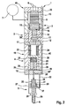
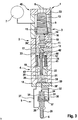
- Fig. 1 to 3 includes a fuel injection system 45 according to the invention at least one injector 1, wherein the fuel injection system 45 may be arranged in particular in a motor vehicle and is used to supply fuel to the individual cylinders of an internal combustion engine. If several injectors 1 are connected to a common high-pressure fuel line or to a common pressure source 7, it is a so-called common-rail system.
- the injector 1 has an injector body 2, which essentially comprises an actuator section 3, a pressure booster section 4 and a needle section 5.
- the actuator section 3 and the pressure booster section 4 are not using one here illustrated connecting element, in particular after the manner of a union nut, firmly connected.
- the injector body 2 In its needle section 5, the injector body 2 has at least one injection hole 6, through which fuel can be injected into an injection space, not shown. Connected to the injector 1 on the one hand hydraulically with a pressure accumulator or a pressure source 7 and on the other hand electrically via corresponding lines 8 with an injection control system.
- the injector 1 has an actuator 9, in particular a piezo actuator, which expands in an activated state with regard to its axial longitudinal extent.
- a valve piston 10 is provided, which has a first valve seat 11 and a second valve seat 12 and which is mounted in a stroke-adjustable manner in the injector body 2.
- the valve piston 10 is mounted adjustable in stroke between a first end position and a second stroke end position, wherein according to the Fig. 1 to 3 the first stroke end position is shown. In this first stroke end position, the first valve seat 11 is closed and the second valve seat 12 is opened, while in the second stroke end position the first valve seat 11 is opened and the second valve seat 12 is closed.
- the actuator 9 is arranged in a pressure chamber 13, which is hydraulically connected to the pressure accumulator or the pressure source 7 and is under system pressure. As a result, the actuator 9 can be arranged to save space within the injector body 2, which has a positive effect on a space requirement.
- the valve piston 10 side facing the actuator 9 has a surrounding this sealing sleeve 14, which is biased by a spring means 15 in the direction of the valve piston 10.
- the sealing sleeve 14, the actuator 9 and the valve piston 10 essentially define a coupler space 16, which is usually separated hydraulically from the pressure chamber 13 by the sealing sleeve 14.
- an intermediate plate 17 is arranged between the actuator section 3 and the pressure booster section 4, while an end plate 18 is arranged on the pressure booster section 4 between the pressure booster section 4 and the needle section 5.
- the pressure booster section 4 is thus axially limited on the one hand by the intermediate plate 17 and on the other hand by the end plate 18.
- a pressure booster 19 is arranged, which essentially comprises a hollow piston 20 and an immersed in this plunger 21 and is designed to increase a fuel injection pressure relative to the system pressure.
- the hollow piston 20 is guided in the pressure booster section 4 and serves as a guide for the coaxial plunging into the hollow piston 20 plunger 21. Together, the hollow piston 20 and the plunger 21 define a pressure booster control chamber 22.
- the System pressure On a the pressure booster control chamber 22 side facing away from the hollow piston 20 is the System pressure, wherein the hollow piston 20 defines on this side together with the intermediate plate 17 and the pressure booster section 4 a hollow piston rear space 23.
- a return spring 24 is provided within the hollow piston rear chamber 23 and connected to the hollow piston 20, which biases the hollow piston 20 of the end plate 18 away.
- an opening spring 25 is arranged, which biases the plunger 21 in the extension from the hollow piston 20, that is, down here.
- a booster chamber 26 is provided, which is bounded in the radial direction on the one hand by the pressure booster section 4 and on the other hand by the plunger 21.
- the booster chamber 26 is connected via a hydraulic path 27 with a nozzle chamber 28.
- a needle closing space 30 is arranged on a side facing away from the injection hole 6 of the nozzle needle 29, in which a needle damper piston 31 is arranged hubver tone and which is connected via a hydraulic line 32 for opening the nozzle needle 29 with a relative to the system pressure unpressurized return 33.
- a rear space 34 of the needle damper piston 31 is hydraulically connected to the hydraulic line 32, wherein the hydraulic line 32 may be throttled differently in the area close to the needle closing chamber 30 and near the rear space 34.
- the needle closing chamber 30 is connected via a further hydraulic line 32 'to the booster chamber 26, wherein in the further hydraulic line 32', a check device 36 is arranged, which is continuous only in the direction of the needle closing chamber 30 to the booster chamber 26.
- the needle damper piston 31 according to the Fig. 1 to 3 crossed by an axial passage opening 35, which is closed at one end by the nozzle needle 29 and the other end communicates with the rear space 34.
- a closing spring 37 is arranged, which biases the needle damper piston 31 in the direction of the nozzle needle 29.
- a coupling path 38 which connects the pressure intensifier control chamber 22 with a plunger chamber 39 hydraulically.
- the plunger piston chamber 39 and thus also the pressure booster control chamber 22 are via corresponding coupling paths 38 'and 38 "in the end plate 18 with a running in a wall of the pressure booster section 4 control line 40 and above depending on the position of the valve piston 10 with the hollow piston rear chamber 23 or the return 33rd hydraulically connected.
- a control rod 41 is provided, which penetrates the hollow piston 20 in the axial direction.
- the control rod 41 On its side facing the intermediate plate 17, the control rod 41 is surrounded by a control sleeve 44 which, together with the control rod 41 and the intermediate plate 17, defines a rod control chamber 42.
- a spring device 15 ' is provided, which biases the control sleeve 44 against the intermediate plate 17.
- a passage 43 is provided which connects the rod control chamber 42 hydraulically with the pressure booster control chamber 22.
- the coupling path 38 is arranged in the plunger 21, so that a connection between the pressure translator control chamber 22 and the plunger piston chamber 39 is also provided.
- no control line 40 is provided in the wall of the pressure booster section 4.
- the reduction of the pressure in the pressure booster control chamber 22 causes a downward movement of the hollow piston 20, whereby the pressure in the booster chamber 26 and thus in the nozzle chamber 28 increases.
- the increase of the pressure in the nozzle chamber 28 and the lowering of the pressure in the back space 34 or in the needle closing space 30 by an appropriate throttling cause an opening movement of the nozzle needle 29, whereby it releases the at least one injection hole 6 and injects fuel into a combustion chamber with increased injection pressure ,
- the actuator 9 is discharged, whereupon it contracts, here moved up and the valve piston 10 moves back to its first stroke end position, in which the first valve seat 11 is closed and the second valve seat 12 is opened.
- the second valve seat 12 of the pressure booster control chamber 22 is subjected to system pressure, whereby the hollow piston 20 intimidveranim to its original position and the pressure in the booster chamber 26 and thus in the nozzle chamber 28 drops.
- the drop in pressure in the nozzle chamber 28 connected to the pressure increase to system pressure in the rear space 34 and in the needle closing chamber 30 cause a closing movement of the nozzle needle 29 and thereby terminating the injection process.
Abstract
Description
Die vorliegende Erfindung betrifft eine Kraftstoffeinspritzanlage für eine Brennkraftmaschine, insbesondere in einem Kraftfahrzeug.The present invention relates to a fuel injection system for an internal combustion engine, in particular in a motor vehicle.
Zur Einbringung von Kraftstoff in direkteinspritzende Dieselmotoren werden zur Zeit vermehrt hubgesteuerte Common-Rail-Systeme eingesetzt, wobei ein Einspritzdruck vorzugsweise an eine Last und eine Drehzahl der Brennkraftmaschine angepasst werden kann. Hierbei hilft insbesondere ein hoher Einspritzdruck, eine Schadstoffemission zu senken und gleichzeitig eine hohe spezifische Leistung zu erzielen. Dieser Einspritzdruck kann weiter gesteigert werden, indem bei Common-Rail-Einspritzsystemen ein Druckverstärker bzw. eine Druckübersetzer angeordnet wird.For the introduction of fuel into direct-injection diesel engines, stroke-controlled common-rail systems are currently being used increasingly, wherein an injection pressure can preferably be adapted to a load and a rotational speed of the internal combustion engine. In particular, a high injection pressure helps to reduce pollutant emissions and at the same time to achieve a high specific power. This injection pressure can be further increased by a pressure booster or a pressure booster is arranged in common-rail injection systems.
Derzeit bekannte Bauformen von Druckübersetzern verwenden üblicherweise einen Stufenkolben als Druckübersetzer, welcher eine Doppelführung aufweist und dadurch über zwei Führungsbereiche in einem Injektor geführt ist. Diese beiden Führungsbereiche müssen für eine reibungslose Funktion des Injektors exakt zueinander ausgerichtet und gefertigt sein, was einen nicht zu unterschätzenden Fertigungsaufwand erfordert. Darüber hinaus ergibt sich eine ungünstige, da lange Bauform des Druckübersetzers.Currently known types of pressure intensifiers usually use a stepped piston as a pressure booster, which has a double guide and is guided over two guide areas in an injector. These two guide areas must be precisely aligned and manufactured for a smooth operation of the injector to each other, which requires a not inconsiderable manufacturing effort. In addition, there is an unfavorable, since long design of the pressure booster.
Aus der
Die erfindungsgemäße Kraftstoffeinspritzanlage mit den Merkmalen des Anspruches 1 hat demgegenüber den Vorteil, dass ein Druckübersetzer eine einfache, koaxiale Bauform mit einem innen liegenden Druckübersetzersteuerraum aufweist, durch welche der Druckübersetzer deutlich kürzer baut. Anstelle eines Druckübersetzers mit einem Stufenkolben, wird der Innenbereich eines Hohlkolbens entlastet, um eine Aktivierung der Übersetzung zu erreichen. Der Entfall der Doppelführung führt darüber hinaus zu deutlich einfacheren Bauteilen, welche kostengünstig herstellbar sind. Ebenso kann auch eine hydraulische Anbindung des Druckübersetzersteuerraums einfach über entsprechende Schnittstellen zwischen unterschiedlichen Abschnitten eines den Druckübersetzer beinhaltenden Injektors erfolgen, wodurch weitere, teure Prozessschritte eingespart werden können.The fuel injection system according to the invention with the features of claim 1 has the advantage that a pressure booster with a simple, coaxial design with an internal pressure booster control chamber through which the pressure booster builds significantly shorter. Instead of a pressure booster with a stepped piston, the interior of a hollow piston is relieved to achieve activation of the translation. The elimination of the double guide also leads to much simpler components, which are inexpensive to produce. Likewise, a hydraulic connection of the pressure booster control chamber can also be effected simply via corresponding interfaces between different sections of an injector containing the pressure booster, as a result of which further, expensive process steps can be saved.
Bei einer bevorzugten Ausführungsform weist die Kraftstoffeinspritzanlage zumindest einen Injektor zum Eindüsen des Kraftstoffs auf, in dem der Druckübersetzer angeordnet bzw. ausgebildet ist. Prinzipiell weist ein solcher Injektor einen Injektorkörper auf, welcher im wesentlichen aus einem Aktorabschnitt, einem Druckübersetzerabschnitt und einem Nadelabschnitt besteht. Zwischen dem Aktorabschnitt und dem Druckübersetzerabschnitt ist dabei eine Zwischenplatte angeordnet, während an einem der Zwischenplatte abgewandten Ende des Druckübersetzerabschnittes eine Endplatte angeordnet ist. Zur Erhöhung eines Kraftstoffeinspritzdruckes gegenüber einem Systemdruck ist im Druckübersetzerabschnitt der Druckübersetzer angeordnet, der einen im Druckübersetzerabschnitt geführten Hohlkolben und einen koaxial in diesen eintauchenden Tauchkolben aufweist, wobei die beiden Kolben einen innen liegenden Druckübersetzersteuerraum begrenzen. Auf einer dem Druckübersetzersteuerraum abgewandten Seite des Hohlkolbens liegt dabei der Systemdruck an. Ein ringförmiger Übersetzerraum des Druckübersetzers, in welchem der hohe Einspritzdruck aufgrund einer Verstellbewegung des Hohlkolbens in Richtung der Endplatte erzeugt wird, wird dabei vom Hohlkolben und von der Endplatte axial begrenzt, während eine radiale Begrenzung des Übersetzerraums durch den Druckübersetzerabschnitt und den Tauchkolben gegeben ist. Jenseits der Endplatte ist der Nadelabschnitt mit einem Düsenraum und einer in diesem hubverstellbaren Düsennadel angeordnet, wobei der Übersetzerraum über einen Hydraulikpfad mit dem Düsenraum verbunden ist. Des Weiteren ist der Düsenraum zum Öffnen der Düsennadel mit einem relativ zum Systemdruck drucklosen Rücklauf verbindbar, so dass indirekt über den Düsenraum auch der Übersetzerraum mit dem Rücklauf verbindbar ist.
Zweckmäßig begrenzt der Aktorabschnitt einen unter Systemdruck stehenden Druckraum, in welchem ein Aktor angeordnet ist. Die Anordnung des Aktors, beispielsweise einesIn a preferred embodiment, the fuel injection system has at least one injector for injecting the fuel, in which the pressure booster is arranged or formed. In principle, such an injector has an injector body, which consists essentially of an actuator section, a pressure booster section and a needle section. In this case, an intermediate plate is arranged between the actuator section and the pressure booster section, while an end plate is arranged on an end of the pressure booster section facing away from the intermediate plate. In order to increase a fuel injection pressure relative to a system pressure, the pressure booster is arranged in the pressure booster section, which has a hollow piston guided in the pressure booster section and a plunger coaxially immersed in the latter, wherein the two pistons delimit an internal pressure booster control chamber. On a side facing away from the pressure translator control chamber side of the hollow piston while the system pressure is applied. An annular translator chamber of the pressure booster, in which the high injection pressure is generated due to an adjustment of the hollow piston in the direction of the end plate, is thereby axially limited by the hollow piston and the end plate, while a radial boundary of the booster chamber is given by the pressure booster section and the plunger. On the other side of the end plate, the needle section is arranged with a nozzle chamber and a nozzle needle which can be adjusted in height, the translator chamber being connected to the nozzle chamber via a hydraulic path. Furthermore, the nozzle space for opening the nozzle needle can be connected to a return line which is unpressurized relative to the system pressure, so that indirectly via the nozzle chamber the interrupter space can also be connected to the return line.
Suitably, the actuator section limits a pressurized space under system pressure, in which an actuator is arranged. The arrangement of the actuator, for example one
Piezo-Aktors, innerhalb des Injektorgehäuses im Aktorabschnitt schafft eine besonders bauraumminimierende Bauweise, welche zudem ein Anordnen eines Aktors außerhalb des Injektors und damit ein aufwendiges Verbinden desselben mit dem Injektor erübrigt. Der Aktor ist dabei über eine Federeinrichtung im Druckraum des Aktorabschnittes verspannt und so lagefixiert angeordnet. In der Zwischenplatte ist ein Kopplungspfad angeordnet, welcher den Druckraum des Aktorabschnitts mit einem, im Druckübersetzerabschnitt auf einer dem Druckübersetzersteuerraum abgewandten Seite des Hohlkolbens gelegenen, Hohlkolbenrückraum hydraulisch verbindet. Hierdurch kann die Zwischenplatte als Kopplungsglied zwischen dem Aktorabschnitt und dem Druckübersetzerabschnitt verwendet werden, wobei durch den Kopplungspfad sowohl im Druckraum als auch im Hohlkolbenrückraum stets der Systemdruck anliegt. Oben genannter Aktor betätigt in aktiviertem Zustand einen hubverstellbar im Aktorabschnitt angeordneten Ventilkolben mit einem ersten und einem zweiten Ventilsitz, wobei in einer ersten Hubendstellung der erste Ventilsitz geschlossen und der zweite Ventilsitz geöffnet ist und in einer zweiten Hubendstellung der erste Ventilsitz geöffnet und der zweite Ventilsitz geschlossen ist. Der Aktor wirkt dabei direkt über einen Kopplerraum auf den Ventilkolben und verstellt diesen zumindest zwischen seinen zwei Hubendstellungen. In der ersten Hubendstellung ist der erste Ventilsitz geschlossen, wodurch eine hydraulische Verbindung zwischen dem Druckübersetzersteuerraum und dem drucklosen Rücklauf unterbrochen ist. Demgegenüber ist der zweite Ventilsitz geöffnet, so dass ein Druckausgleich zwischen dem Druckübersetzersteuerraum und dem Hohlkolbenrückraum und damit über den Kopplungspfad auch mit dem Druckraum und einer daran angeschlossenen Druckquelle möglich ist. In seiner zweiten Hubendstellung ist wie oben erwähnt, der erste Ventilsitz geöffnet, so dass eine hydraulische Verbindung zwischen dem Druckübersetzersteuerraum und dem drucklosen Rücklauf gegeben ist, während eine Verbindung zwischen dem Druckübersetzersteuerraum und dem Hohlkolbenrückraum unterbrochen ist. Der Ventilkolben mit seinen zwei Ventilsitzen bietet dabei den großen Vorteil, eine Steuerfunktion konstruktiv einfach ausführen zu können und zugleich extrem kurze Schaltzeiten zu ermöglichen.Piezo-actuator, within the injector in Aktorabschnitt creates a particularly space-minimizing construction, which also eliminates the need to arrange an actuator outside of the injector and thus a complex connection of the same with the injector. The actuator is braced via a spring device in the pressure chamber of Aktorabschnittes and arranged fixed in position. In the intermediate plate, a coupling path is arranged, which hydraulically connects the pressure chamber of the Aktorabschnitts with a, located in the pressure booster section on a side facing away from the pressure booster control chamber side of the hollow piston, the hollow piston rear. In this way, the intermediate plate can be used as a coupling member between the actuator section and the pressure booster section, wherein the system pressure is always applied by the coupling path both in the pressure chamber and in the hollow piston rear space. The above-mentioned actuator actuates in the activated state a stroke adjustable arranged in Aktorabschnitt valve piston having a first and a second valve seat, wherein in a first stroke end of the first valve seat closed and the second valve seat is open and opened in a second stroke end of the first valve seat and the second valve seat closed is. The actuator acts directly on a coupler space on the valve piston and adjusts this at least between its two stroke end positions. In the first stroke end position of the first valve seat is closed, whereby a hydraulic connection between the pressure translator control chamber and the non-pressurized return is interrupted. In contrast, the second valve seat is open, so that a pressure equalization between the pressure booster control chamber and the hollow piston rear space and thus via the coupling path with the pressure chamber and a pressure source connected thereto is possible. As mentioned above, in its second stroke end position, the first valve seat is opened, so that a hydraulic connection between the pressure booster control chamber and the non-pressurized return is provided, while a connection between the pressure booster control chamber and the hollow piston rear space is interrupted. The valve piston with its two valve seats offers the great advantage of being able to perform a control function structurally simple and at the same time to allow extremely short switching times.
Bei einer vorteilhaften Weiterbildung der erfindungsgemäßen Lösung ist die Düsennadel so ausgebildet, dass eine Druckbeaufschlagung des Düsenraums eine Öffnungsbewegung der Düsennadel unterstützt. Dabei weist die Düsennadel eine Anströmfläche auf, welche dem Düsenraum zugewandt ist und welche bei einer Druckbeaufschlagung des Düsenraums zu einer Öffnungsbewegung der Düsennadel führt. Bei einer Erniedrigung des Drucks im Düsenraum sorgt eine Düsennadelfeder, die in einem Nadelschließraum angeordnet ist und welche die Düsennadel in ihre Schließstellung vorspannt dafür, dass die Düsennadel in ihre Schließstellung verfährt und das wenigstens eine Spritzloch verschließt. Durch den derart ausgebildeten Düsenraum bzw. die so ausgebildete Düsennadel wird der hydraulische Druck im Düsenraum zusammen mit einer Düsennadelfeder in konstruktiv genialer Weise dazu verwendet, die Öffnungs- bzw. Schließbewegung der Düsennadel zu steuern, wobei aufgrund der Kopplung der Düsennadelfeder mit dem entgegenwirkenden Druck im Düsenraum ein extrem schneller Schaltvorgang erzielt werden kann.In an advantageous embodiment of the solution according to the invention, the nozzle needle is designed so that pressurization of the nozzle chamber supports an opening movement of the nozzle needle. In this case, the nozzle needle has an inflow surface, which faces the nozzle chamber and which leads to an opening movement of the nozzle needle when pressure is applied to the nozzle chamber. At a decrease in pressure in Nozzle space provides a nozzle needle spring which is arranged in a needle closing space and which biases the nozzle needle into its closed position for the nozzle needle to move into its closed position and to close the at least one injection hole. By the thus formed nozzle chamber or the nozzle needle thus formed, the hydraulic pressure in the nozzle chamber is used together with a nozzle needle spring in a structurally ingenious way to control the opening and closing movement of the nozzle needle, due to the coupling of the nozzle needle spring with the counteracting pressure in Nozzle space an extremely fast switching operation can be achieved.
Weitere wichtige Merkmale und Vorteile der Erfindung ergeben sich aus den Unteransprüchen, aus den Zeichnungen und aus der zugehörigen Figurenbeschreibung anhand der Zeichnungen.Other important features and advantages of the invention will become apparent from the dependent claims, from the drawings and from the associated figure description with reference to the drawings.
Ausführungsbeispiele der Erfindung sind in den Zeichnungen dargestellt und werden im folgenden näher erläutert, wobei sich gleiche Bezugszeichen auf gleiche oder ähnliche oder funktional gleiche Komponenten beziehen. Es zeigen jeweils schematisch,
- Fig. 1 bis Fig. 3
- eine Kraftstoffeinspritzanlage mit einem stark vereinfachten, prinzipiellen Längsschnitt durch einen, einen Druckübersetzer aufweisenden Injektor bei verschiedenen Ausführungsformen.
- Fig. 1 to Fig. 3
- a fuel injection system with a much simplified, schematic longitudinal section through a, a pressure booster having injector in various embodiments.
Entsprechend den
Der Injektor 1 weist in seinem Aktorabschnitt 3 einen Aktor 9, insbesondere einen Piezo-Aktor auf, welcher sich in aktiviertem Zustand hinsichtlich seiner axialen Längserstreckung ausdehnt. Des Weiteren ist im Aktorabschnitt 3 ein Ventilkolben 10 vorgesehen, welcher einen ersten Ventilsitz 11 und einen zweiten Ventilsitz 12 aufweist und welcher hubverstellbar im Injektorkörper 2 gelagert ist. Dabei ist der Ventilkolben 10 zwischen einer ersten Endstellung und einer zweiten Hubendstellung hubverstellbar gelagert, wobei gemäß den
Der Aktor 9 ist in einem Druckraum 13 angeordnet, welcher hydraulisch mit dem Druckspeicher bzw. der Druckquelle 7 verbunden ist und unter Systemdruck steht. Dadurch kann der Aktor 9 platzsparend innerhalb des Injektorkörpers 2 angeordnet werden, was sich positiv auf einen Bauraumbedarf auswirkt. Auf seiner, dem Ventilkolben 10 zugewandten Seite, weist der Aktor 9 eine diesen umgebende Dichthülse 14 auf, welche über eine Federeinrichtung 15 in Richtung des Ventilkolbens 10 vorgespannt ist. Die Dichthülse 14, der Aktor 9 und der Ventilkolben 10 begrenzen dabei im wesentlichen einen Kopplerraum 16, welcher üblicherweise hydraulisch vom Druckraum 13 durch die Dichthülse 14 getrennt ist.The
Wie den
In axialer Richtung zwischen dem Hohlkolben 20 und der Endplatte 18 ist ein Übersetzerraum 26 vorgesehen, welcher in radialer Richtung einerseits vom Druckübersetzerabschnitt 4 und andererseits vom Tauchkolben 21 begrenzt ist. Der Übersetzerraum 26 ist dabei über einen Hydraulikpfad 27 mit einem Düsenraum 28 verbunden. Des Weiteren ist auf einer dem Spritzloch 6 abgewandten Seite der Düsennadel 29 ein Nadelschließraum 30 angeordnet, in welchem ein Nadeldämpferkolben 31 hubverstellbar angeordnet ist und welcher über eine Hydraulikleitung 32 zum Öffnen der Düsennadel 29 mit einem relativ zum Systemdruck drucklosen Rücklauf 33 verbindbar ist. Dabei ist auch ein Rückraum 34 des Nadeldämpferkolbens 31 mit der Hydraulikleitung 32 hydraulisch verbunden, wobei die Hydraulikleitung 32 im Bereich nahe beim Nadelschließraum 30 bzw. nahe beim Rückraum 34 unterschiedlich gedrosselt sein kann. Gemäß der Ausführungsvariante nach
Zurückkommend auf den Tauchkolben 21 ist zu bemerken, dass dieser in axialer Richtung von einem Kopplungspfad 38 durchdrungen ist, welcher den Druckübersetzersteuerraum 22 mit einem Tauchkolbenraum 39 hydraulisch verbindet. Der Tauchkolbenraum 39 und damit auch der Druckübersetzersteuerraum 22 sind über entsprechende Kopplungspfade 38' und 38" in der Endplatte 18 mit einer, in einer Wandung des Druckübersetzerabschnittes 4 verlaufenden Steuerleitung 40 und darüber je nach Stellung des Ventilkolbens 10 mit dem Hohlkolbenrückraum 23 oder dem Rücklauf 33 hydraulisch verbunden.Coming back to the
Bei der Ausführungsform des Injektors gemäß der
Prinzipiell funktionieren alle Injektoren 1 gemäß den
Im Ausgangszustand sind zunächst alle Räume 13, 16, 22, 26, 28 und 30 mit dem Versorgungsdruck, d.h. dem Systemdruck, der Druckquelle/des Druckspeichers 7 beaufschlagt und der Druckübersetzer 19 ist deaktiviert. Die Düsennadel 29 ist in diesem Zustand so angeordnet, dass sie das wenigstens eine Spritzloch 6 verschließt. Bei Aktivierung eines nicht gezeigten Ventils wird der Aktor 9 geladen, woraufhin er sich nach unten ausdehnt und den Ventilkolben 10 nach unten bewegt. Dies hat zur Folge, dass sich der erste Ventilsitz 11 öffnet und somit der Druckübersetzersteuerraum 22, der Tauchkolben 39, der Rückraum 34 und der Nadelschließraum 30 mit dem im wesentlichen drucklosen Rücklauf 33 hydraulisch verbunden werden. Die Reduzierung des Drucks im Druckübersetzersteuerraum 22 bewirkt ein nach unten Fahren des Hohlkolbens 20, wodurch der Druck im Übersetzerraum 26 und damit im Düsenraum 28 ansteigt. Das Ansteigen des Drucks im Düsenraum 28 und das durch eine entsprechende Drosselung leicht zeitverzögerte Absenken des Drucks im Rückraum 34 bzw. im Nadelschließraum 30 bewirken eine Öffnungsbewegung der Düsennadel 29, wodurch diese das wenigstens eine Spritzloch 6 freigibt und mit erhöhtem Einspritzdruck Kraftstoff in einen Brennraum einspritzt.In the initial state, all
Zum Beenden des Einspritzvorganges wird der Aktor 9 entladen, woraufhin dieser sich zusammenzieht, hier nach oben bewegt und der Ventilkolben 10 in seine erste Hubendstellung zurückfährt, in welcher der erste Ventilsitz 11 geschlossen und der zweite Ventilsitz 12 geöffnet ist. Durch das Öffnen des zweiten Ventilsitzes 12 ist der Druckübersetzersteuerraum 22 mit Systemdruck beaufschlagt, wodurch der Hohlkolben 20 in seine Ausgangsstellung zurückverfährt und der Druck im Übersetzerraum 26 und damit im Düsenraum 28 abfällt. Das Abfallen des Drucks im Düsenraum 28 verbunden mit der Druckerhöhung auf Systemdruck im Rückraum 34 und im Nadelschließraum 30 bewirken eine Schließbewegung der Düsennadel 29 und dadurch das Beenden des Einspritzvorganges.To terminate the injection process, the
Dieser Vorgang wird durch die drei unterschiedlichen Ausführungsformen des Injektors 1 auf unterschiedliche Weise realisiert, ist jedoch vom Ablauf her in allen drei Fällen im wesentlichen gleich.This process is realized in different ways by the three different embodiments of the injector 1, but is essentially the same in all three cases in terms of the process.
Claims (12)
- Fuel injection system (45) of an internal combustion engine, in particular in a motor vehicle, having a pressure booster (19) for increasing a fuel injection pressure in relation to a system pressure, characterized in that the pressure booster (19) has a hollow piston (20) guided in a pressure booster section (4) and has a plunger piston (21) which plunges coaxially into said hollow piston, with the hollow piston (20) and the plunger piston (21) delimiting a pressure booster control chamber (22), and with the system pressure prevailing on a side of the hollow piston (20) facing away from the pressure booster control chamber (22).
- Fuel injection system according to Claim 1,
characterized- in that the fuel injection system (45) comprises at least one injector (1),- in that the pressure booster (19) is a constituent part of the injector (1). - Fuel injection system according to Claim 2,
characterized- in that the injector (1) has an injector body (2) which comprises an actuator section (3), a pressure booster section (4) and a needle section (5),- with an intermediate plate (17) being arranged between the actuator section (3) and the pressure booster section (4), and with the pressure booster section (4) having an end plate (18) on its side facing away from the intermediate plate (17),- with the needle section (5) having a nozzle chamber (28) and a stroke-adjustable nozzle needle (29) for controlling an injection of fuel through at least one spray hole (6),- with the hollow piston (20) and the end plate (18) axially delimiting an annular booster chamber (26) of the pressure booster (19), while the pressure booster section (4) and the plunger piston (21) delimit the booster chamber (26) in the radial direction,- with the booster chamber (26) being connected via a hydraulic path (27) to the nozzle chamber (28) of the needle section (5),- with a needle closing chamber (30) being provided which is situated opposite the nozzle chamber (28) in relation to the nozzle needle (29) and which can be connected to a return line (33), which is unpressurized relative to the system pressure, in order to open the nozzle needle (29). - Fuel injection system according to Claim 3,
characterized- in that a valve piston (10) having a first and a second valve seat (11, 12) is arranged in stroke-adjustable fashion in the actuator section (3), wherein the first valve seat (11) is closed and the second valve seat (12) is open in a first stroke end position and vice versa in a second stroke end position, and/or- in that the actuator section (3) delimits a pressure chamber (13) which is at system pressure and in which an actuator (9) is arranged, and/or- in that a coupling path (38") is arranged in the intermediate plate (17), which coupling path (38") hydraulically connects the pressure chamber (13) to a hollow piston rear chamber (23) which is situated in the pressure booster section (4) on a side of the hollow piston (20) facing away from the pressure booster control chamber (22). - Fuel injection system according to one of Claims 1 to 4,
characterized
in that a restoring spring (24) is provided which forces the hollow piston (20) away from the end plate (18). - Fuel injection system according to one of Claims 1 to 5,
characterized
in that an opening spring (25) is provided which is arranged in the pressure booster control chamber (22) and which preloads the plunger piston (21) out of the hollow piston (20) in the extending direction. - Fuel injection system according to one of Claims 3 to 6,
characterized- in that a control line (40) is arranged in a wall of the pressure booster section (4), which control line (40), depending on the stroke end position of the valve piston (10), hydraulically connects the pressure booster control chamber (22) via a coupling path (38, 38') in the end plate either to the pressure chamber (13) in the actuator section (3) or to the unpressurized return line (33),- in that a hydraulic line (32) to a rear chamber (34) of a needle damper piston (31) and to a needle closing chamber (30) branches off from the control line (40),- in that the hydraulic lines (32) are subjected to different degrees of throttling. - Fuel injection system according to Claim 7,
characterized
in that the needle closing chamber (30) is hydraulically connected via a further hydraulic line (32') to the booster chamber (26), with a check valve (36) being arranged in the further hydraulic line (32'), which check valve (36) allows a passage of flow only in the direction of the booster chamber (26). - Fuel injection system according to one of Claims 1 to 7,
characterized
in that a control rod (41) is provided which plunges at one end into the pressure booster control chamber (22) and extends through the hollow piston (20) in the axial direction. - Fuel injection system according to Claim 9,
characterized- in that a coupling path (43) which hydraulically connects the pressure booster control chamber (22) and the rod control chamber (42) to one another is formed coaxially within the control rod (41),- in that a control sleeve (44) is provided on that end of the control rod (41) which faces towards the intermediate plate (17), which control sleeve (44) together with the intermediate plate (17) delimits a rod control chamber (42). - Fuel injection system according to one of Claims 3 to 10,
characterized
in that the nozzle needle (29) is designed such that a pressurization of the nozzle chamber (28) assists an opening movement of the nozzle needle (29). - Injector (1) for a fuel injection system (45) according to one of Claims 1 to 11.
Applications Claiming Priority (1)
| Application Number | Priority Date | Filing Date | Title |
|---|---|---|---|
| DE102006047134A DE102006047134A1 (en) | 2006-10-05 | 2006-10-05 | Fuel injection system |
Publications (3)
| Publication Number | Publication Date |
|---|---|
| EP1908953A2 EP1908953A2 (en) | 2008-04-09 |
| EP1908953A3 EP1908953A3 (en) | 2009-06-17 |
| EP1908953B1 true EP1908953B1 (en) | 2011-01-19 |
Family
ID=38896948
Family Applications (1)
| Application Number | Title | Priority Date | Filing Date |
|---|---|---|---|
| EP07114426A Not-in-force EP1908953B1 (en) | 2006-10-05 | 2007-08-16 | Fuel injection device |
Country Status (3)
| Country | Link |
|---|---|
| EP (1) | EP1908953B1 (en) |
| AT (1) | ATE496215T1 (en) |
| DE (2) | DE102006047134A1 (en) |
Families Citing this family (2)
| Publication number | Priority date | Publication date | Assignee | Title |
|---|---|---|---|---|
| FI122557B (en) * | 2009-04-02 | 2012-03-30 | Waertsilae Finland Oy | Fuel injection arrangement for a piston engine |
| WO2014193356A1 (en) * | 2013-05-29 | 2014-12-04 | International Engine Intellectual Property Company, Llc | Fuel injector |
Family Cites Families (2)
| Publication number | Priority date | Publication date | Assignee | Title |
|---|---|---|---|---|
| DE10218635A1 (en) * | 2001-05-17 | 2002-11-28 | Bosch Gmbh Robert | Fuel injection device for internal combustion engine has closure pressure chamber forming working chamber with another chamber and all parts of working chamber are interconnected |
| DE10249840A1 (en) * | 2002-10-25 | 2004-05-13 | Robert Bosch Gmbh | Fuel injection device for internal combustion engines |
-
2006
- 2006-10-05 DE DE102006047134A patent/DE102006047134A1/en not_active Withdrawn
-
2007
- 2007-08-16 AT AT07114426T patent/ATE496215T1/en active
- 2007-08-16 EP EP07114426A patent/EP1908953B1/en not_active Not-in-force
- 2007-08-16 DE DE502007006293T patent/DE502007006293D1/en active Active
Also Published As
| Publication number | Publication date |
|---|---|
| DE102006047134A1 (en) | 2008-04-10 |
| EP1908953A2 (en) | 2008-04-09 |
| ATE496215T1 (en) | 2011-02-15 |
| EP1908953A3 (en) | 2009-06-17 |
| DE502007006293D1 (en) | 2011-03-03 |
Similar Documents
| Publication | Publication Date | Title |
|---|---|---|
| EP1654455B1 (en) | Control valve for a fuel injector that contains a pressure intensifier | |
| EP1756415B1 (en) | Fuel injector with variable actuator transmission | |
| EP1853813B1 (en) | Injection nozzle | |
| EP1831539B1 (en) | Fuel injector with direct control of the injection valve body | |
| EP0976924B1 (en) | Injector with a servo valve | |
| WO2007000371A1 (en) | Injector with a pressure intensifier that can be switched on | |
| EP1908952B1 (en) | Injector for a fuel injection system | |
| EP2150696B1 (en) | Injector for a fuel injection system | |
| EP1126160B1 (en) | Injector for injecting fuel in an internal combustion engine | |
| DE102008002416A1 (en) | Fuel injector has injector housing or body, high-pressure chambers or storages, which are constantly connected with high-pressure source for fuel, and nozzle needle | |
| EP1872008B1 (en) | Fuel-injector with two-stage opening | |
| EP1682769B1 (en) | Fuel injector with a multipart, directly controlled injection valve element | |
| DE10249840A1 (en) | Fuel injection device for internal combustion engines | |
| DE10353045A1 (en) | Fuel injection valve | |
| EP1908953B1 (en) | Fuel injection device | |
| DE102008002412A1 (en) | Fuel injector for injecting fuel into e.g. direct-injection diesel engine, has actuator coupled with nozzle needle, where actuator and head pistons on one side and needle and slave piston on another side exhibit different stroke axis | |
| EP1703118B1 (en) | Injector nozzle | |
| DE102006022803A1 (en) | Injection nozzle for internal combustion engine of motor vehicle, has preloading piston loaded with preloading force in preloading side, where preloading force actuates preloading piston against bypass plunger | |
| DE102005024721B4 (en) | Common rail injector | |
| DE102008002415A1 (en) | Fuel injector has injector housing or body and high pressure chambers arranged in housing, which is connected with high pressure source for fuel and with combustion chamber for injecting fuel by injection nozzle | |
| DE10019767A1 (en) | Valve for controlling liquids | |
| DE102004038189A1 (en) | Fuel injector linked to a high pressure fuel supply, for an IC motor, has an inner and a coaxial outer needle with separate control zones and switch valves | |
| DE19947196A1 (en) | Fuel injection device for diesel engine has control valve for regulating fuel feed from high pressure space to injection valve | |
| EP2133552B1 (en) | Fuel injector | |
| DE10333693B3 (en) | Fuel injection device for an internal combustion engine comprises a filling chamber arranged between two pistons and connected to a feed line |
Legal Events
| Date | Code | Title | Description |
|---|---|---|---|
| PUAI | Public reference made under article 153(3) epc to a published international application that has entered the european phase |
Free format text: ORIGINAL CODE: 0009012 |
|
| AK | Designated contracting states |
Kind code of ref document: A2 Designated state(s): AT BE BG CH CY CZ DE DK EE ES FI FR GB GR HU IE IS IT LI LT LU LV MC MT NL PL PT RO SE SI SK TR |
|
| AX | Request for extension of the european patent |
Extension state: AL BA HR MK RS |
|
| PUAL | Search report despatched |
Free format text: ORIGINAL CODE: 0009013 |
|
| AK | Designated contracting states |
Kind code of ref document: A3 Designated state(s): AT BE BG CH CY CZ DE DK EE ES FI FR GB GR HU IE IS IT LI LT LU LV MC MT NL PL PT RO SE SI SK TR |
|
| AX | Request for extension of the european patent |
Extension state: AL BA HR MK RS |
|
| 17P | Request for examination filed |
Effective date: 20091217 |
|
| AKX | Designation fees paid |
Designated state(s): AT BE BG CH CY CZ DE DK EE ES FI FR GB GR HU IE IS IT LI LT LU LV MC MT NL PL PT RO SE SI SK TR |
|
| 17Q | First examination report despatched |
Effective date: 20100129 |
|
| GRAP | Despatch of communication of intention to grant a patent |
Free format text: ORIGINAL CODE: EPIDOSNIGR1 |
|
| GRAS | Grant fee paid |
Free format text: ORIGINAL CODE: EPIDOSNIGR3 |
|
| GRAA | (expected) grant |
Free format text: ORIGINAL CODE: 0009210 |
|
| AK | Designated contracting states |
Kind code of ref document: B1 Designated state(s): AT BE BG CH CY CZ DE DK EE ES FI FR GB GR HU IE IS IT LI LT LU LV MC MT NL PL PT RO SE SI SK TR |
|
| REG | Reference to a national code |
Ref country code: GB Ref legal event code: FG4D Free format text: NOT ENGLISH |
|
| REG | Reference to a national code |
Ref country code: CH Ref legal event code: EP |
|
| REG | Reference to a national code |
Ref country code: IE Ref legal event code: FG4D Free format text: LANGUAGE OF EP DOCUMENT: GERMAN |
|
| REF | Corresponds to: |
Ref document number: 502007006293 Country of ref document: DE Date of ref document: 20110303 Kind code of ref document: P |
|
| REG | Reference to a national code |
Ref country code: DE Ref legal event code: R096 Ref document number: 502007006293 Country of ref document: DE Effective date: 20110303 |
|
| REG | Reference to a national code |
Ref country code: NL Ref legal event code: VDEP Effective date: 20110119 |
|
| LTIE | Lt: invalidation of european patent or patent extension |
Effective date: 20110119 |
|
| PG25 | Lapsed in a contracting state [announced via postgrant information from national office to epo] |
Ref country code: IS Free format text: LAPSE BECAUSE OF FAILURE TO SUBMIT A TRANSLATION OF THE DESCRIPTION OR TO PAY THE FEE WITHIN THE PRESCRIBED TIME-LIMIT Effective date: 20110519 Ref country code: SE Free format text: LAPSE BECAUSE OF FAILURE TO SUBMIT A TRANSLATION OF THE DESCRIPTION OR TO PAY THE FEE WITHIN THE PRESCRIBED TIME-LIMIT Effective date: 20110119 Ref country code: LV Free format text: LAPSE BECAUSE OF FAILURE TO SUBMIT A TRANSLATION OF THE DESCRIPTION OR TO PAY THE FEE WITHIN THE PRESCRIBED TIME-LIMIT Effective date: 20110119 Ref country code: LT Free format text: LAPSE BECAUSE OF FAILURE TO SUBMIT A TRANSLATION OF THE DESCRIPTION OR TO PAY THE FEE WITHIN THE PRESCRIBED TIME-LIMIT Effective date: 20110119 Ref country code: PT Free format text: LAPSE BECAUSE OF FAILURE TO SUBMIT A TRANSLATION OF THE DESCRIPTION OR TO PAY THE FEE WITHIN THE PRESCRIBED TIME-LIMIT Effective date: 20110519 Ref country code: ES Free format text: LAPSE BECAUSE OF FAILURE TO SUBMIT A TRANSLATION OF THE DESCRIPTION OR TO PAY THE FEE WITHIN THE PRESCRIBED TIME-LIMIT Effective date: 20110430 Ref country code: GR Free format text: LAPSE BECAUSE OF FAILURE TO SUBMIT A TRANSLATION OF THE DESCRIPTION OR TO PAY THE FEE WITHIN THE PRESCRIBED TIME-LIMIT Effective date: 20110420 |
|
| REG | Reference to a national code |
Ref country code: IE Ref legal event code: FD4D |
|
| PG25 | Lapsed in a contracting state [announced via postgrant information from national office to epo] |
Ref country code: CY Free format text: LAPSE BECAUSE OF FAILURE TO SUBMIT A TRANSLATION OF THE DESCRIPTION OR TO PAY THE FEE WITHIN THE PRESCRIBED TIME-LIMIT Effective date: 20110119 Ref country code: BG Free format text: LAPSE BECAUSE OF FAILURE TO SUBMIT A TRANSLATION OF THE DESCRIPTION OR TO PAY THE FEE WITHIN THE PRESCRIBED TIME-LIMIT Effective date: 20110419 Ref country code: NL Free format text: LAPSE BECAUSE OF FAILURE TO SUBMIT A TRANSLATION OF THE DESCRIPTION OR TO PAY THE FEE WITHIN THE PRESCRIBED TIME-LIMIT Effective date: 20110119 Ref country code: PL Free format text: LAPSE BECAUSE OF FAILURE TO SUBMIT A TRANSLATION OF THE DESCRIPTION OR TO PAY THE FEE WITHIN THE PRESCRIBED TIME-LIMIT Effective date: 20110119 Ref country code: SI Free format text: LAPSE BECAUSE OF FAILURE TO SUBMIT A TRANSLATION OF THE DESCRIPTION OR TO PAY THE FEE WITHIN THE PRESCRIBED TIME-LIMIT Effective date: 20110119 Ref country code: FI Free format text: LAPSE BECAUSE OF FAILURE TO SUBMIT A TRANSLATION OF THE DESCRIPTION OR TO PAY THE FEE WITHIN THE PRESCRIBED TIME-LIMIT Effective date: 20110119 |
|
| PG25 | Lapsed in a contracting state [announced via postgrant information from national office to epo] |
Ref country code: DK Free format text: LAPSE BECAUSE OF FAILURE TO SUBMIT A TRANSLATION OF THE DESCRIPTION OR TO PAY THE FEE WITHIN THE PRESCRIBED TIME-LIMIT Effective date: 20110119 Ref country code: EE Free format text: LAPSE BECAUSE OF FAILURE TO SUBMIT A TRANSLATION OF THE DESCRIPTION OR TO PAY THE FEE WITHIN THE PRESCRIBED TIME-LIMIT Effective date: 20110119 Ref country code: IE Free format text: LAPSE BECAUSE OF FAILURE TO SUBMIT A TRANSLATION OF THE DESCRIPTION OR TO PAY THE FEE WITHIN THE PRESCRIBED TIME-LIMIT Effective date: 20110119 |
|
| PLBE | No opposition filed within time limit |
Free format text: ORIGINAL CODE: 0009261 |
|
| STAA | Information on the status of an ep patent application or granted ep patent |
Free format text: STATUS: NO OPPOSITION FILED WITHIN TIME LIMIT |
|
| PG25 | Lapsed in a contracting state [announced via postgrant information from national office to epo] |
Ref country code: RO Free format text: LAPSE BECAUSE OF FAILURE TO SUBMIT A TRANSLATION OF THE DESCRIPTION OR TO PAY THE FEE WITHIN THE PRESCRIBED TIME-LIMIT Effective date: 20110119 Ref country code: SK Free format text: LAPSE BECAUSE OF FAILURE TO SUBMIT A TRANSLATION OF THE DESCRIPTION OR TO PAY THE FEE WITHIN THE PRESCRIBED TIME-LIMIT Effective date: 20110119 Ref country code: CZ Free format text: LAPSE BECAUSE OF FAILURE TO SUBMIT A TRANSLATION OF THE DESCRIPTION OR TO PAY THE FEE WITHIN THE PRESCRIBED TIME-LIMIT Effective date: 20110119 |
|
| 26N | No opposition filed |
Effective date: 20111020 |
|
| PG25 | Lapsed in a contracting state [announced via postgrant information from national office to epo] |
Ref country code: IT Free format text: LAPSE BECAUSE OF FAILURE TO SUBMIT A TRANSLATION OF THE DESCRIPTION OR TO PAY THE FEE WITHIN THE PRESCRIBED TIME-LIMIT Effective date: 20110119 Ref country code: MT Free format text: LAPSE BECAUSE OF FAILURE TO SUBMIT A TRANSLATION OF THE DESCRIPTION OR TO PAY THE FEE WITHIN THE PRESCRIBED TIME-LIMIT Effective date: 20110119 |
|
| REG | Reference to a national code |
Ref country code: DE Ref legal event code: R097 Ref document number: 502007006293 Country of ref document: DE Effective date: 20111020 |
|
| BERE | Be: lapsed |
Owner name: ROBERT BOSCH G.M.B.H. Effective date: 20110831 |
|
| PG25 | Lapsed in a contracting state [announced via postgrant information from national office to epo] |
Ref country code: MC Free format text: LAPSE BECAUSE OF NON-PAYMENT OF DUE FEES Effective date: 20110831 |
|
| REG | Reference to a national code |
Ref country code: CH Ref legal event code: PL |
|
| GBPC | Gb: european patent ceased through non-payment of renewal fee |
Effective date: 20110816 |
|
| PG25 | Lapsed in a contracting state [announced via postgrant information from national office to epo] |
Ref country code: CH Free format text: LAPSE BECAUSE OF NON-PAYMENT OF DUE FEES Effective date: 20110831 Ref country code: LI Free format text: LAPSE BECAUSE OF NON-PAYMENT OF DUE FEES Effective date: 20110831 |
|
| PG25 | Lapsed in a contracting state [announced via postgrant information from national office to epo] |
Ref country code: BE Free format text: LAPSE BECAUSE OF NON-PAYMENT OF DUE FEES Effective date: 20110831 |
|
| PG25 | Lapsed in a contracting state [announced via postgrant information from national office to epo] |
Ref country code: GB Free format text: LAPSE BECAUSE OF NON-PAYMENT OF DUE FEES Effective date: 20110816 |
|
| PG25 | Lapsed in a contracting state [announced via postgrant information from national office to epo] |
Ref country code: LU Free format text: LAPSE BECAUSE OF NON-PAYMENT OF DUE FEES Effective date: 20110816 |
|
| PG25 | Lapsed in a contracting state [announced via postgrant information from national office to epo] |
Ref country code: TR Free format text: LAPSE BECAUSE OF FAILURE TO SUBMIT A TRANSLATION OF THE DESCRIPTION OR TO PAY THE FEE WITHIN THE PRESCRIBED TIME-LIMIT Effective date: 20110119 |
|
| REG | Reference to a national code |
Ref country code: AT Ref legal event code: MM01 Ref document number: 496215 Country of ref document: AT Kind code of ref document: T Effective date: 20120831 |
|
| PG25 | Lapsed in a contracting state [announced via postgrant information from national office to epo] |
Ref country code: HU Free format text: LAPSE BECAUSE OF FAILURE TO SUBMIT A TRANSLATION OF THE DESCRIPTION OR TO PAY THE FEE WITHIN THE PRESCRIBED TIME-LIMIT Effective date: 20110119 Ref country code: AT Free format text: LAPSE BECAUSE OF NON-PAYMENT OF DUE FEES Effective date: 20120831 |
|
| REG | Reference to a national code |
Ref country code: FR Ref legal event code: PLFP Year of fee payment: 10 |
|
| PGFP | Annual fee paid to national office [announced via postgrant information from national office to epo] |
Ref country code: FR Payment date: 20160825 Year of fee payment: 10 |
|
| PGFP | Annual fee paid to national office [announced via postgrant information from national office to epo] |
Ref country code: DE Payment date: 20171026 Year of fee payment: 11 |
|
| REG | Reference to a national code |
Ref country code: FR Ref legal event code: ST Effective date: 20180430 |
|
| PG25 | Lapsed in a contracting state [announced via postgrant information from national office to epo] |
Ref country code: FR Free format text: LAPSE BECAUSE OF NON-PAYMENT OF DUE FEES Effective date: 20170831 |
|
| REG | Reference to a national code |
Ref country code: DE Ref legal event code: R119 Ref document number: 502007006293 Country of ref document: DE |
|
| PG25 | Lapsed in a contracting state [announced via postgrant information from national office to epo] |
Ref country code: DE Free format text: LAPSE BECAUSE OF NON-PAYMENT OF DUE FEES Effective date: 20190301 |