EP1830713B1 - Aiguille fine rotative pour le prelevement de tissus organiques internes - Google Patents
Aiguille fine rotative pour le prelevement de tissus organiques internes Download PDFInfo
- Publication number
- EP1830713B1 EP1830713B1 EP05849971A EP05849971A EP1830713B1 EP 1830713 B1 EP1830713 B1 EP 1830713B1 EP 05849971 A EP05849971 A EP 05849971A EP 05849971 A EP05849971 A EP 05849971A EP 1830713 B1 EP1830713 B1 EP 1830713B1
- Authority
- EP
- European Patent Office
- Prior art keywords
- needle
- shaft member
- subassembly
- set forth
- elongate
- Prior art date
- Legal status (The legal status is an assumption and is not a legal conclusion. Google has not performed a legal analysis and makes no representation as to the accuracy of the status listed.)
- Active
Links
- 238000005070 sampling Methods 0.000 title description 18
- 230000033001 locomotion Effects 0.000 claims abstract description 23
- 239000002184 metal Substances 0.000 claims description 34
- 239000005321 cobalt glass Substances 0.000 claims 1
- 230000001939 inductive effect Effects 0.000 claims 1
- 238000001574 biopsy Methods 0.000 abstract description 44
- 230000009471 action Effects 0.000 abstract description 5
- 238000013188 needle biopsy Methods 0.000 abstract description 4
- 210000001519 tissue Anatomy 0.000 description 62
- 238000000034 method Methods 0.000 description 33
- 230000003902 lesion Effects 0.000 description 22
- 210000000056 organ Anatomy 0.000 description 17
- 210000004027 cell Anatomy 0.000 description 12
- 239000000523 sample Substances 0.000 description 10
- 238000002604 ultrasonography Methods 0.000 description 10
- 210000000481 breast Anatomy 0.000 description 9
- 230000007246 mechanism Effects 0.000 description 9
- 229910001220 stainless steel Inorganic materials 0.000 description 9
- 239000010935 stainless steel Substances 0.000 description 9
- 238000003780 insertion Methods 0.000 description 8
- 230000037431 insertion Effects 0.000 description 8
- HLXZNVUGXRDIFK-UHFFFAOYSA-N nickel titanium Chemical compound [Ti].[Ti].[Ti].[Ti].[Ti].[Ti].[Ti].[Ti].[Ti].[Ti].[Ti].[Ni].[Ni].[Ni].[Ni].[Ni].[Ni].[Ni].[Ni].[Ni].[Ni].[Ni].[Ni].[Ni].[Ni] HLXZNVUGXRDIFK-UHFFFAOYSA-N 0.000 description 7
- 229910001000 nickel titanium Inorganic materials 0.000 description 7
- 210000003813 thumb Anatomy 0.000 description 7
- 210000000496 pancreas Anatomy 0.000 description 6
- 208000012266 Needlestick injury Diseases 0.000 description 5
- 206010028980 Neoplasm Diseases 0.000 description 5
- 239000003755 preservative agent Substances 0.000 description 5
- 230000002335 preservative effect Effects 0.000 description 5
- 206010061902 Pancreatic neoplasm Diseases 0.000 description 4
- 238000003745 diagnosis Methods 0.000 description 4
- 210000003811 finger Anatomy 0.000 description 4
- 239000012530 fluid Substances 0.000 description 4
- 208000014674 injury Diseases 0.000 description 4
- 210000004185 liver Anatomy 0.000 description 4
- 239000000463 material Substances 0.000 description 4
- 201000002528 pancreatic cancer Diseases 0.000 description 4
- 230000002787 reinforcement Effects 0.000 description 4
- 230000000472 traumatic effect Effects 0.000 description 4
- 210000001835 viscera Anatomy 0.000 description 4
- 230000008901 benefit Effects 0.000 description 3
- 239000002775 capsule Substances 0.000 description 3
- 210000004872 soft tissue Anatomy 0.000 description 3
- 239000000243 solution Substances 0.000 description 3
- 230000008733 trauma Effects 0.000 description 3
- 206010049082 Pancreatic mass Diseases 0.000 description 2
- 210000000601 blood cell Anatomy 0.000 description 2
- 230000008878 coupling Effects 0.000 description 2
- 238000010168 coupling process Methods 0.000 description 2
- 238000005859 coupling reaction Methods 0.000 description 2
- 238000013461 design Methods 0.000 description 2
- 210000001198 duodenum Anatomy 0.000 description 2
- 239000013013 elastic material Substances 0.000 description 2
- 238000009558 endoscopic ultrasound Methods 0.000 description 2
- 210000001035 gastrointestinal tract Anatomy 0.000 description 2
- 230000000968 intestinal effect Effects 0.000 description 2
- 239000007788 liquid Substances 0.000 description 2
- 239000006193 liquid solution Substances 0.000 description 2
- 238000012317 liver biopsy Methods 0.000 description 2
- 210000002445 nipple Anatomy 0.000 description 2
- 208000008443 pancreatic carcinoma Diseases 0.000 description 2
- 230000000849 parathyroid Effects 0.000 description 2
- 230000035515 penetration Effects 0.000 description 2
- 229920001343 polytetrafluoroethylene Polymers 0.000 description 2
- 239000004810 polytetrafluoroethylene Substances 0.000 description 2
- 239000007787 solid Substances 0.000 description 2
- 210000001685 thyroid gland Anatomy 0.000 description 2
- 238000013519 translation Methods 0.000 description 2
- 210000004881 tumor cell Anatomy 0.000 description 2
- 206010006187 Breast cancer Diseases 0.000 description 1
- 208000026310 Breast neoplasm Diseases 0.000 description 1
- 102000004190 Enzymes Human genes 0.000 description 1
- 108090000790 Enzymes Proteins 0.000 description 1
- 206010018852 Haematoma Diseases 0.000 description 1
- 239000004809 Teflon Substances 0.000 description 1
- 229920006362 Teflon® Polymers 0.000 description 1
- 208000007536 Thrombosis Diseases 0.000 description 1
- 208000027418 Wounds and injury Diseases 0.000 description 1
- 230000003187 abdominal effect Effects 0.000 description 1
- 230000005540 biological transmission Effects 0.000 description 1
- 230000002380 cytological effect Effects 0.000 description 1
- 230000000120 cytopathologic effect Effects 0.000 description 1
- 230000006378 damage Effects 0.000 description 1
- 230000034994 death Effects 0.000 description 1
- 238000000151 deposition Methods 0.000 description 1
- 230000029087 digestion Effects 0.000 description 1
- 102000038379 digestive enzymes Human genes 0.000 description 1
- 108091007734 digestive enzymes Proteins 0.000 description 1
- 230000002183 duodenal effect Effects 0.000 description 1
- 238000001861 endoscopic biopsy Methods 0.000 description 1
- 238000012336 endoscopic ultrasonography Methods 0.000 description 1
- 210000003238 esophagus Anatomy 0.000 description 1
- 238000011156 evaluation Methods 0.000 description 1
- 208000021045 exocrine pancreatic carcinoma Diseases 0.000 description 1
- 238000000605 extraction Methods 0.000 description 1
- 238000011010 flushing procedure Methods 0.000 description 1
- 210000005224 forefinger Anatomy 0.000 description 1
- 230000006870 function Effects 0.000 description 1
- 238000010231 histologic analysis Methods 0.000 description 1
- 235000015243 ice cream Nutrition 0.000 description 1
- 230000000977 initiatory effect Effects 0.000 description 1
- 238000002347 injection Methods 0.000 description 1
- 239000007924 injection Substances 0.000 description 1
- 238000011862 kidney biopsy Methods 0.000 description 1
- 208000015486 malignant pancreatic neoplasm Diseases 0.000 description 1
- 239000007769 metal material Substances 0.000 description 1
- 230000001394 metastastic effect Effects 0.000 description 1
- 206010061289 metastatic neoplasm Diseases 0.000 description 1
- 238000012986 modification Methods 0.000 description 1
- 230000004048 modification Effects 0.000 description 1
- 230000017074 necrotic cell death Effects 0.000 description 1
- 230000003287 optical effect Effects 0.000 description 1
- 210000004923 pancreatic tissue Anatomy 0.000 description 1
- 230000001575 pathological effect Effects 0.000 description 1
- 230000007170 pathology Effects 0.000 description 1
- 230000008569 process Effects 0.000 description 1
- 210000002307 prostate Anatomy 0.000 description 1
- 230000035807 sensation Effects 0.000 description 1
- 239000012781 shape memory material Substances 0.000 description 1
- 238000010186 staining Methods 0.000 description 1
- 210000002784 stomach Anatomy 0.000 description 1
- 238000011477 surgical intervention Methods 0.000 description 1
- 238000001356 surgical procedure Methods 0.000 description 1
- 230000004614 tumor growth Effects 0.000 description 1
- 238000011179 visual inspection Methods 0.000 description 1
- 238000012800 visualization Methods 0.000 description 1
Images


Classifications
-
- A—HUMAN NECESSITIES
- A61—MEDICAL OR VETERINARY SCIENCE; HYGIENE
- A61B—DIAGNOSIS; SURGERY; IDENTIFICATION
- A61B17/00—Surgical instruments, devices or methods, e.g. tourniquets
- A61B17/32—Surgical cutting instruments
- A61B17/320016—Endoscopic cutting instruments, e.g. arthroscopes, resectoscopes
- A61B17/32002—Endoscopic cutting instruments, e.g. arthroscopes, resectoscopes with continuously rotating, oscillating or reciprocating cutting instruments
-
- A—HUMAN NECESSITIES
- A61—MEDICAL OR VETERINARY SCIENCE; HYGIENE
- A61B—DIAGNOSIS; SURGERY; IDENTIFICATION
- A61B10/00—Other methods or instruments for diagnosis, e.g. instruments for taking a cell sample, for biopsy, for vaccination diagnosis; Sex determination; Ovulation-period determination; Throat striking implements
- A61B10/02—Instruments for taking cell samples or for biopsy
- A61B10/0233—Pointed or sharp biopsy instruments
- A61B10/0266—Pointed or sharp biopsy instruments means for severing sample
-
- A—HUMAN NECESSITIES
- A61—MEDICAL OR VETERINARY SCIENCE; HYGIENE
- A61B—DIAGNOSIS; SURGERY; IDENTIFICATION
- A61B10/00—Other methods or instruments for diagnosis, e.g. instruments for taking a cell sample, for biopsy, for vaccination diagnosis; Sex determination; Ovulation-period determination; Throat striking implements
- A61B10/02—Instruments for taking cell samples or for biopsy
- A61B10/0233—Pointed or sharp biopsy instruments
- A61B10/0283—Pointed or sharp biopsy instruments with vacuum aspiration, e.g. caused by retractable plunger or by connected syringe
-
- A—HUMAN NECESSITIES
- A61—MEDICAL OR VETERINARY SCIENCE; HYGIENE
- A61B—DIAGNOSIS; SURGERY; IDENTIFICATION
- A61B10/00—Other methods or instruments for diagnosis, e.g. instruments for taking a cell sample, for biopsy, for vaccination diagnosis; Sex determination; Ovulation-period determination; Throat striking implements
- A61B10/02—Instruments for taking cell samples or for biopsy
- A61B10/04—Endoscopic instruments
-
- A—HUMAN NECESSITIES
- A61—MEDICAL OR VETERINARY SCIENCE; HYGIENE
- A61B—DIAGNOSIS; SURGERY; IDENTIFICATION
- A61B10/00—Other methods or instruments for diagnosis, e.g. instruments for taking a cell sample, for biopsy, for vaccination diagnosis; Sex determination; Ovulation-period determination; Throat striking implements
- A61B10/02—Instruments for taking cell samples or for biopsy
- A61B10/0233—Pointed or sharp biopsy instruments
- A61B10/0266—Pointed or sharp biopsy instruments means for severing sample
- A61B10/0275—Pointed or sharp biopsy instruments means for severing sample with sample notch, e.g. on the side of inner stylet
-
- A—HUMAN NECESSITIES
- A61—MEDICAL OR VETERINARY SCIENCE; HYGIENE
- A61B—DIAGNOSIS; SURGERY; IDENTIFICATION
- A61B17/00—Surgical instruments, devices or methods, e.g. tourniquets
- A61B17/32—Surgical cutting instruments
- A61B17/3205—Excision instruments
- A61B17/32053—Punch like cutting instruments, e.g. using a cylindrical or oval knife
-
- A—HUMAN NECESSITIES
- A61—MEDICAL OR VETERINARY SCIENCE; HYGIENE
- A61B—DIAGNOSIS; SURGERY; IDENTIFICATION
- A61B10/00—Other methods or instruments for diagnosis, e.g. instruments for taking a cell sample, for biopsy, for vaccination diagnosis; Sex determination; Ovulation-period determination; Throat striking implements
- A61B10/02—Instruments for taking cell samples or for biopsy
- A61B2010/0225—Instruments for taking cell samples or for biopsy for taking multiple samples
-
- A—HUMAN NECESSITIES
- A61—MEDICAL OR VETERINARY SCIENCE; HYGIENE
- A61B—DIAGNOSIS; SURGERY; IDENTIFICATION
- A61B10/00—Other methods or instruments for diagnosis, e.g. instruments for taking a cell sample, for biopsy, for vaccination diagnosis; Sex determination; Ovulation-period determination; Throat striking implements
- A61B10/02—Instruments for taking cell samples or for biopsy
- A61B10/04—Endoscopic instruments
- A61B2010/045—Needles
-
- A—HUMAN NECESSITIES
- A61—MEDICAL OR VETERINARY SCIENCE; HYGIENE
- A61B—DIAGNOSIS; SURGERY; IDENTIFICATION
- A61B17/00—Surgical instruments, devices or methods, e.g. tourniquets
- A61B2017/0046—Surgical instruments, devices or methods, e.g. tourniquets with a releasable handle; with handle and operating part separable
Definitions
- This invention relates to a medical instrument for use in the application of tissue sampling.
- An instrument in accordance with this invention is usable with ultrasound, and in some cases an ultrasound-endoscope for performing a needle biopsy operation on a patient's internal body tissues at a surgical site not visible to the unaided eye.
- Fine needle aspiration has been a well accepted method for obtaining tissue samples for pathologic or histologic analysis in diagnosing tumors of the pancreas and other soft tissue organs.
- Endoscopic ultrasound (EUS) and EUS-guided fine needle aspiration (EUS-FNA) have become important tools in the evaluation of pancreatic masses.
- This needle is passed through the working channel of a linear echo endoscope under real-time guidance into the endo-sonographically visualized pancreatic mass.
- the needle is moved back and forth multiple times through the lesion with varying degrees of suction applied to it.
- the specimens obtained are then deposited onto a cytology slide for immediate fixation, staining and cytopathologic examination.
- Aspirating a sample from a fluid medium through a needle is a simple procedure. Aspirating a sample from a solid mass is difficult. Most pancreatic EUS-FNA procedures take up to 30 needle passes to make a definitive cytological diagnosis of pancreatic carcinoma. Oftentimes, the only cells that are obtained are blood cells, or normal pancreatic tissue cells. Even when tumor cells are captured, these are often fragmented, and separated from each other. It is therefore almost impossible to differentiate a primary pancreatic tumor from a metastatic lesion.
- the needle is then pushed into the incision, and under aspiration is quickly pushed in and out of the liver with a quick stabbing motion.
- the resulting core biopsy is almost always diagnostic, and ample to examine sheets of tissue cells representative of the pathology that is sought.
- the injury is much greater than that inflicted with a fine needle.
- the choices for obtaining diagnostic tissue from internal organs are three fold.
- the first choice is to obtain a biopsy though an open operative incision or a laparoscopic technique, which entails surgical intervention.
- the second option is to use a large diameter stiff stainless steel needle. This method may only be used for lesions that are near the exterior of the body, such as described above in relation to the Mangini needle.
- the third method is to obtain cells through a fine needle with ultrasound guidance. While this method is least traumatic with only one needle introduction, it produces a poor yield of diagnostic material. In the best case scenario, and after multiple needle sticks, several cells of the tumor are retrieved. Because the cells are obtained separate from one another, they are examined by the pathologist without their spatial relationship to the rest of the organ that they originated from.
- the fine needle aspiration technique is also widely used to obtain cells from suspected lesions in organs that are more superficial. These organs include breast, prostate, thyroid and parathyroid. Although these organs are more accessible to the needle than the pancreas, the trauma incurred by a thick core biopsy needle stick is great. Millions of women undergo fine needle aspirations for suspected breast cancer. Here too, 10-15 needle sticks are required to obtain what is deemed a sufficient number of cells for an adequate specimen.
- the present invention aims to provide an improved medical instrument for the removal of core biopsy tissue samples for diagnostic purposes though a fine needle. More specifically, the invention aims to provide a needle assembly that requires only a minimal number of needle passes into the organ tissue. Preferably, all the above-mentioned benefits are attained by using a needle of the same small gauge as is currently used in the state of the art of the fine needle aspiration technique, so as not to cause undue trauma to the pancreas or other internal organs that are samples.
- the present invention further aims to provide an instrument for more superficial organ lesions such as breast, with a needle that is as thin as the fine needle currently used for aspiration, but enabling only a single passage with a resultant core biopsy.
- such an instrument is easy to use and can accomplish the desired result in a short period of time, while being cost effective.
- This invention thus seeks to enable in part the performance of a fine needle aspiration requiring only one or two needle passes, with resultant tissue sampling which is more substantival providing the opportunity for a definitive diagnosis.
- a method for obtaining a coring needle biopsy from selected portions of internal body tissues of a patient utilizes a flexible hollow tubular shaft member, preferably of a metal material, with a needle shaped at its most distal end, the tubular shaft member being slidably disposed within an outer sheath member.
- the outer sheath member has a diameter sufficiently small to enable its insertion into the working channel of a flexible endoscope.
- the outer sheath member is reinforced by means of a metal coil embedded into the sheath's well. While the outer sheath member may be made of Teflon, or PTFE, the metal coil or otherwise braided reinforcement may be made of stainless steel, or a shape memory metal such as Nitinol. This reinforcement by a metal coil or otherwise braided structure renders the outer sheath sturdy, yet flexible. This feature supports the actuation of the elongated inner metal needle.
- the inner flexible hollow tubular member may be made of stainless steel, or a shape memory metal such as Nitinol. While being flexible enough to pass through an elongated flexible endoscope, it is also sturdy enough to provide the required stiffness to form the distal needle enabling introduction into the organ requiring tissue sampling.
- This inner metal shaft member is slidably disposed within the outer sheath member, occupying all, or almost all of the length of the outer sheath member, terminating at its distal end with a specially shaped needle to be discussed further herein below.
- An actuator sub-assembly is operatively connected to the proximal end of the inner tubular shaft member. When actuated, the handle assembly pushes the elongate needle, or inner tubular shaft member with distal needle shape, in and out of the outer sheath.
- a camming subassembly is provided preferably in the handle subassembly for converting a linear motion of the inner tubular shaft member, applied proximally by the operator, at least partially into a rotating motion of the distal end of the inner tubular shaft member.
- the elongate inner tubular shaft member may be provided with a syringe attachment port at its proximal end, the syringe port communicating with the lumen of this tubular member.
- a stainless steel, Nitinol, or other metal guide wire may be passed through the inner tubular shaft member with distal needle shape, in order to further stabilize it while piercing tissue.
- the guide-wire's most distal end may be shaped as a needle as well.
- the distal needle-shaped end of the inner tubular shaft member is configured as a spoon not unlike the shape of an ice-cream scooper.
- the distal spoon-shaped, needle end is provided with a sharp piercing tip, and very sharp edges extending from the needle tip or point.
- the handle sub-assembly includes a short metal pipe or tube provided with a spiral cutout or groove along which the key element slides during at least a portion of a distally directed motion of the inner tubular shaft member.
- the short metal pipe or tube is disposed at a proximal location inside the handle assembly, affixed to the handle assembly.
- the elongated needle is slidably disposed within the catheter or sheath, capable of passing freely through it.
- the spiral groove or track and the key element inserted into the groove or track function as a camming mechanism, which converts a linear translation into a rotary motion.
- This feature provides for the turning motion of the entire inner tubular shaft member and consequently its needle shaped distal end, for capturing the desired tissue sample.
- a method for obtaining a core biopsy specimen from tissue not accessible to endoscopic visualization comprises the steps of (a) inserting an endoscope equipped with an ultrasound assembly into a patient, and advancing it intraluminally towards the area that lies closest to the organ wherein a lesion is suspected, (b) using the endoscope-ultrasound assembly to project ultrasonic vibrations from the endoscope into extraluminal organs to visually inspect the suspected lesion on an exterior screen, (c) delineating the suspicious lesion or tissue mass ultrasonographically, (d) moving the sheath member of the invention in a distal direction through a working channel of an endoscope to eject the sheath member from the working channel, (e) after detecting the lesion or tissue mass ultrasonographically, shitting an actuator slider in a distal direction to thereby eject the inner tubular shaft member needle element from the sheath member, the needle element being an integral part of the inner the inner tubular shaft member (f) piercing an intestinal wall with the needles element under endoscopic guidance
- the needle element of whatever configuration, is connectable to a source of electrical current for effectuating a cauterization of internal tissues during passage of the instrument through the tissues.
- a cauterization feature facilitates penetration of the needle element into or through hard internal tissues that form a capsule about soft tissues. Without the cauterization capability, attempting to push the needle through the capsule into the soft tissues typically results in a mere deformation of the capsulated tissues, preventing penetration of the needle element.
- the present invention contemplates that there may be a guide wire that is inserted into the inner tubular shaft member.
- This shaft member is made of a solid flexible material such as stainless steel, or preferably Nitinol.
- the guide wire provides further stability and firmness to the needle, especially when it is passed through an intestinal wall, and into a capsule of an organ.
- the needle is provided along at least a portion of its length with a plurality of longitudinally spaced apertures for the dispensing of a liquid solution into internal tissues.
- the apertures may also be staggered circumferentially about the needle element.
- a method for obtaining a needle biopsy from selected portions of internal body tissues of a patient utilizes, in accordance with another embodiment of the present invention, a flexible hollow tubular member provided at a distal ed with a hollow needle tip, the tubular member and needle being disposed in an outer sheath member.
- the outer sheath member has a diameter sufficiently small to enable its insertion into the working channel of a flexible endoscope.
- An actuator sub-assembly is operatively connected to the hollow tubular member's proximal end so as to allow the tubular member with distally connected needle to be ejected from the outer sheath member or catheter.
- a camming subassembly is included for converting a linear motion of the tubular member partially into a rotating motion of the needle element. This rotation facilitates the collection of a core biopsy.
- the elongate tubular member may be provided with a syringe attachment port at its proximal end, the syringe port communicating with the lumen of the tubular member.
- the needle's distal end is configured in the shape of a spoon with a sharp piercing tip and sharp edges extending proximally form the needle tip.
- Located on the proximal portion of the needle-shaft is a small stub element.
- the distal sub-assembly includes a short metal tube, the tube provided with a spiral cutout.
- the short metal tube is disposed in a fixed state at a distal location of the catheter, affixed to an outer metal collet, the collet providing the most distal portion of the catheter.
- the needle which is slidably disposed within the catheter is capable of passing freely through the metal tube.
- the camming mechanism includes a spiral groove or track and a key inserted into the groove or track and may be located at a proximal end of the instrument, within an actuator handle.
- the key element engages with the proximal aspect of the short metal tube's spiral cutout.
- a tactile sensation perceived by the operator holding the actuating handle occurs when the needle's stub hits the metal tube.
- additional forward advancement of the actuator will initiate a rotation of the needle (a camming action) within the tumor mass, "scooping out” a core biopsy specimen with the spoon shaped needle's end. This process is visualized both endoscopically and ultrasonographically.
- a syringe is attached to the proximally located port, and aspirated to bring the core biopsy into the needle's lumen.
- the needle is then withdrawn into the sheath, and the entire assembly is extracted from the biopsy channel of the endoscope.
- the specimen is then ejected into preservative solution or onto a slide by injecting fluid through the port,
- Another embodiment of the present invention provides a rotatable fine needle for obtaining core biopsy tissue from more superficially located organs with a suspected mass lesion.
- the needle length is contemplated to be about the same as that of a fine needle currently used for aspiration of cells. Its distal end is spoon shaped, similar to that of the endoscopic core biopsy fine needle.
- the camming mechanism is preferably located in the handle in this instrument as well. Because the handle assembly includes the camming mechanism, it is longer than the handle used in a needle that is attached to a syringe only. It is not ergonomically comfortable to hold such a long handle assembly with a thumb ring being located on the proximal end of the handle.
- the instrument is provided with a handle assembly wherein the thumb ring is attached on a lateral aspect of the handle, rather than at its most proximal end.
- a grip for the fingers is provided more distally on the handle, in the shape of a spool, being further elucidated in the drawings, and described below.
- an interchangeable thumb ring and syringe attachment is provided for the shorter needles, also further described herein below.
- a method for obtaining a core biopsy specimen from a more superficial organ such as breast comprises, the steps of (a) using an external ultrasound probe to localize and delineate a suspected mass lesion in a patient, (b) inserting a needle through the patient's skin, and pushing the needle towards and into the mass lesion under ultrasound guidance, (c) shifting an actuator slider in a distal direction, thereby engaging a camming mechanism to cause a tip of the needle to rotate 360 degrees within the mass lesion, thereby severing a tissue sample from the mass lesion, (d) aspirating the tissue sample deeper into the needle using a syringe attached to a proximal end of the needle, (e) removing the needle from the tissue, and (f) injecting a liquid through the needle causing the core biopsy to be ejected into the preservative solution.
- Tubular shaft member 22 is provided at a proximal and with a port 24 that communicates with the lumen of the tubular shaft member.
- needle element 20 may be an integral distal tip of shaft member 22.
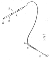
- the instrument assembly of Fig. 1 includes an actuator subassembly 26 including a cylindrical body portion 28 carrying a slidably mounted shifter 30. Shifter is connected to tubular shaft member 22 for moving the tubular shaft member alternatively in the distal direction and the proximal direction through a flexible tubular sheath 32 that is fixed at a proximal end to cylindrical body portion 28. Sheath 32 has a sufficiently small diameter to enable insertion of the sheath, together with tubular shaft member 22 into a biopsy channel 61. of an endoscope insertion member 46, both shown in Fig 3 .
- Needle element 20 is made of a super-elastic material such as Nitinol. Needle element 20 has a predetermined rest configuration, usually straight. The application of an external force of a limited magnitude to the needles element 20 may deform it out of the rest configuration and into another configuration. Needle element 20 will however spring back to its straight or other predetermined configuration upon cessation or termination of the external force.
- Sheath member 32 is made of a polymeric material such as PTFE (TeflonTM) reinforced by means of a metal coil embedded into the sheath's wall.
- the metal coil or otherwise braided reinforcement may be made of stainless steel or a shape memory metal such as Nitinol. This reinforcement by a metal coil or otherwise braided structure renders the outer sheath 32 sturdy yet flexible and supports the actuation of the elongated inner metal needle 20.
- needle element 20 possesses a distal end configured in the shape of a spoon 34 with a sharp piercing tip or point 36.
- Spoon 34 may be provided with sharp curved lateral edges 37 for facilitating the cutting of internal body tissues during an endoscopic biopsy operation.
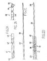
- a camming mechanism may be provided at the distal end of sheath 32.
- the camming mechanism includes a key element or cam follower at the proximal end of needle element 20 in the form of a small laterally or transversely extending stub 38.
- needle element 20 widens into tubular shaft structure 22 also made of flexible material which may or may not be a similar super-elastic material such as that of needle element 20.
- Tubular structure 22 may be made of stainless steel or a shape memory material such as Nitinol, same as needle element 20. Needle element 20 and tubular structure 22 are housed inside sheath 32. At the distal end of sheath 32 there is a metal collar 40 which is coupled with tubular member 32.
- a distal subassembly 48 includes a metal tube 41 having a spiral cutout or slot 42. Spiral cutout 42 terminates at the proximal end 45 of metal tube 41 and is spaced from the distal end 43 of metal tube 41.
- Needle element 20 has a distal end 29 in the form of spoon 34 with the spoon's distal end tapering to a sharp tip or point 36.
- Fig. 2D shows subassembly 48 assembled in its functioning configuration. As shown, stub 38 is fitted within spiral cutout 42 of metal tube 41. Metal tube 41 is coupled with and partially contained inside metal collar 40 and extends in a proximal direction into sheath 32.
- distal subassembly 48 is designed to optimize the utilization of the instrument assembly of Fig. 1 in obtaining a core biopsy possibly indicative of a tumor growth from an internal body organ or tissue.
- endoscope insertion member 46 is inserted through a patient's mouth, through the esophagus and stomach into the duodenum.
- insertion member 46 is provided with optical elements such as a lens 60 to enable visual inspection of an inner wall 62 of the duodenum and a light source 63 to illuminate these internal body parts.
- optical elements such as a lens 60 to enable visual inspection of an inner wall 62 of the duodenum and a light source 63 to illuminate these internal body parts.
- needle element 20 is ejected from subassembly 48 by manipulating actuator subassembly 26 ( Fig. 1 ) in the distal direction. As shown in Fig. 5 , needle element 20 is introduced through duodenal wall 62 in the direction of mass 64.
- stub 38 is spaced from slotted metal tube 41.
- needle element 20 reaches the interior of mass 64, illustrated in an ultrasound picture (not shown)
- continued pushing of needle element 20 engages stub 38 into spiral cutout 42 of metal tube 41.
- Further distal pushing of needle element 20 now induces needle element 20 to rotate inside tumor 64 due to a camming action of stub 38 against edges or surfaces of spiral cutout 42 in metal tube 41.
- This camming action causes the sharp spoon shaped distal tip or point 29 of needle element 20 and edges 37 to scoop out a core of tissue from tumor 64.
- a syringe (not shown) is attached to port 24 and operated to aspirate the tissue sample into the lumen of needle element 20.
- needle element 20 is retracted into sheath 32 ( Fig. 7 ), and the entire assembly is withdrawn from biopsy channel 61 of endoscope 46.
- the specimen is then ejected into preservative by injecting fluid through port 24 into the lumen of tubular shaft member 22 and needle element 20.
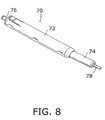
- the camming subassembly (tube 14, spiral cutout 42, stub or follower 38) is a structural arrangement for converting a linear motion partially into a rotary motion and may be located at any position along tubular shaft member 22, particularly inside actuator subassembly 26. Such an alternative design is depicted in Figs. 8-11 .
- Figs. 8-10 depict a handle or actuator assembly 70 of a core tissue sampling instrument that may be used in an endoscopic procedure utilizing optics alone or optics in conjunction with endoscopic ultrasonography.
- an instrument includes a flexible sheath member and a flexible shaft member as discussed above.
- handle or actuator assembly 70 may be part of a breast biopsy instrument having a substantially rigid tubular shaft member, or needle. Preferably, this would be a stainless steel needle.
- Handle or actuator assembly 70 includes an outer plunger handle or shifter 72 that telescopingly receives, in a distal end, a tubular plunger 74.
- Plunger handle or housing 72 is provided at a proximal end with a nipple or port element 76 for receiving a nozzle part of a syringe (not shown), while plunger 74 is provided at a distal end with a connector 78 for coupling to a tubular sheath member (not shown).
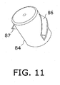
- a tubular needle shaft 80 extends through connector 78, plunger 74, and handle or housing 72 and connects at a proximal end to a cap 82 rotatably seated in a cylindrical compartment 84 at the proximal end of plunger handle 72. Needle shaft 80 communicates with nipple or port element 76 via cap 82.
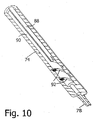
- a cylindrical carrier or stylist 84 on needle shaft 80 exhibits a pair of outwardly projecting spiral rib or flange sections 86, 87 ( Fig. 11 ) serving as keys or cam followers.
- Spiral rib or flange sections 86, 87 are substantially triangular in cross-section as shown in Fig. 11 .
- a pair of linear grooves or keyways 88 extend longitudinally along an inner surface 90 of plunger 74 and communicate or intersect at their distal ends with respective spiral cutouts or grooves 92 in inner surface 90 of plunger 74.
- plunger 74 steady or fixed relative to a patient while moving handle or shifter 72 in a distal direction over the plunger.
- rib or flange sections 86, 87 are each located in and guided by a respective groove or keyway 88 while needle shaft 80 translates distally.
- rib or flange sections 86, 87 enter respective spiral cutouts or grooves 92 and are constrained to follow those cutouts or grooves, thereby imparting a rotational motion to carrier or stylist 84 and needle shaft 80.
- Cutouts or grooves 92 thus define camming surfaces, tracks or keyways that convert linear motion of needle shaft 80 at least partially into a rotational motion.
- spiral cutouts or grooves 92 communicate or intersect with linear grooves or keyways 88.
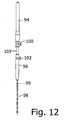
- Fig. 12 depicts a modified core tissue sampling instrument that incorporates the internal functional elements of the embodiment of Figs. 8-11 .
- the instrument of Fig. 12 includes a handle or shifter member 94, a plunger member 96 and a tubular needle shaft 98 extending through a tubular sheath member 99.
- One or more set screws 100, 102 may be provided for fixing plunger 96 relative to handle 94.
- Plunger member 96 includes a tube 103 that is inserted into handle member 94.
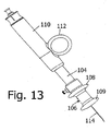
- Fig. 13 depicts another variation of the core tissue sampling instrument of Figs. 8-11 particularly useful for breast biopsies and core tissue sampling of other superficial orans.
- a plunger part 104 is provided with a spool 106 having a pair of opposed flanges 108 and 109 for receiving a forefinger and a middle finger of a user.
- An outer tubular handle or shifter member 110 is provided along a lateral surface (not separately designated) with a thumb ring 112. Finger spool 106 and thumb ring 112 enable a user to hold the device and control the movement of a hollow needle shaft 114 with one hand.
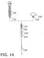
- FIG. 14 shows yet another variation of the core tissue sampling instrument of Figs. 8-11 .
- a hollow needle shaft 116 extending through a tubular sheath member 117 is connected to a proximal end of a plunger part 118 that is provided with a finger spool 120.
- Plunger part 118 is slidably connected to a handle or shifter part 122 provided at a proximal end with an internally threaded screw connector 124 for removably coupling to a syringe 126 and alternatively to a thumb ring 128.
- Syringe 126 and thumb ring 128 are formed at their distal ends with externally threaded screw connectors 130 and 132 that mate with screw connector 124.
- any of the embodiments of a core tissue sampling instrument described and illustrated herein, particularly including the embodiments of 12 -13 may be used with rigid needle shafts, e.g., shafts 98, 114, 116, in a percutaneous tissue sampling procedure, Such a procedure is followed, for example, to extract breast biopsy specimens.
- the needle shafts 98, 114, 116, etc. all have operative tips in the form of sharp needle points as discussed hereinabove particularly with reference to Fig. 2B .
- the sharp needle tips are preferably integrally formed parts of the respective needle shafts.
- sheath members 99,115,117 are omitted.
- the percutaneous core tissue sampling instrument exemplarily of Figs. 12-14 may be used for prostrate, thyroid, parathyroid, and perhaps liver and kidney biopsy extraction, as well as in obtaining breast biopsies.
- a method for obtaining a core biopsy specimen from a superficial organ uses an ultrasound probe to localize and delineate a suspected mass lesion in an internal organ of a patient.
- the method additionally comprises inserting the needle tip portion of needle shaft 98, 114, 116 through the patient's skin, pushing the needle towards and into the mass lesion under ultrasound guidance, shifting actuator handle or shifter member 94, 110, 122 in a distal direction, and during that shifting engaging the associated camming mechanism to cause a tip of the needle to rotate 360 degrees within the mass lesion, thereby severing a tissue sample from the mass lesion.
- the tissue sample is aspirated deeper into the needle (e.g., by operating a syringe), the needle is removed from the tissue, and a liquid is injected through the needle, causing the core biopsy to be ejected into a preservative solution.
- any core tissue sampling instrument described and illustrated herein may be provided with an electrical connector operatively linked to the needle element for enabling the transmission of a cauterization current to a target tissue site internal to the patient
- cauterization is described hereinabove with reference to Figs. 1-7 .
- any of the needle tips disclosed herein may be provided along at least a portion of its length with a plurality of longitudinally spaced apertures 134 for the dispensing of a liquid solution into internal tissues. Apertures 134 may be staggered circumferentially about the needle.
- Fig. 15 is a schematic view of an upper portion of a patient's digestive tract, showing a step in an endoscopic procedure utilizing a core tissue sampling instrument 136 having an actuator subassembly 138 (as shown in Fig. 12 ), a flexible tubular sheath 140 with a distal end portion 142, and a flexible tubular needle shaft 144. Sheath 140 with needle shaft 144 therein is inserted through a biopsy channel (not shown) in a flexible endoscope insertion member 146.
- the operator Upon locating of a target biopsy site ultrasonographically, the operator advances sheath 140 and needle shaft 144 in a distal direction through the biopsy channel so that distal end portion 142 of sheath 140 and a needle tip 148 emerge from the distal end of the endoscope insertion member 146. Needle shaft 144 is further advanced so that needle tip 148 is inserted into a target tissue mass 150 inside the patient's liver 152. Further details of this procedure are described hereinabove with reference to Figs. 3-7 .
- camming mechanism including stub 38 and metal tube 41, may be used to generate a rotary motion from a longitudinal translation in other kinds of endoscopic instruments including, for instance, cauterization snare capture pockets.
Claims (9)
- Ensemble instrument médical comprenant:un élément (22) de tige allongé;une pointe active disposée sur une extrémité distale (29) dudit élément (22) de tige allongé;un élément (32) de gaine allongé logeant au moins partiellement ledit élément (22) de tige allongé et ladite pointe active;un sous-ensemble d'actionnement (26) comportant un levier (94, 110, 122) relié fonctionnellement à une extrémité proximale dudit élément (22) de tige allongé de sorte qu'une poussée ou une traction dudit levier (94, 110, 122) fait avancer respectivement ladite pointe active dans une direction distale ou fait rétracter ladite pointe active dans une direction proximale ; et un sous-ensemble à came,
caractérisé en ce que ledit sous-ensemble à came est relié fonctionnellement audit élément (22) de tige et audit levier (94, 110, 122) pour induire un mouvement rotatif de ladite pointe active lors d'un mouvement dudit levier (94, 110, 122). - Ensemble instrument selon la revendication 1, dans lequel ledit sous-ensemble à came comprend un élément en spirale et une clavette (38) coopérant avec ledit élément en spirale.
- Ensemble instrument selon la revendication 2, dans lequel ledit élément en spirale est une découpe ou rainure (42) et ladite clavette (38) est en saillie.
- Ensemble instrument selon la revendication 3, dans lequel ladite clavette (38) est fixée à et dépasse transversalement dudit élément (22) de tige allongé, ladite clavette (38) pouvant être insérée dans et mise en prise avec ladite découpe ou rainure (42), ladite découpe ou rainure (42) étant fixe par rapport à au moins un dudit élément (32) de gaine tubulaire et à un corps dudit sous-ensemble d'actionnement (26) et définissant une gorge ou un logement de clavette permettant audit élément (22) de tige allongé de tourner lors d'un déplacement distal dudit élément (22) de tige.
- Ensemble instrument selon l'une quelconque des revendications précédentes, dans lequel ledit élément (32) de gaine allongé présente un diamètre extérieur suffisamment petit de manière à ce que ledit élément (32) de gaine allongé puisse être inséré à travers un canal d'un endoscope (146) souple.
- Ensemble instrument selon l'une quelconque des revendications précédentes, dans lequel :ledit élément (22) de tige allongé est un élément tubulaire (22) allongé configuré avec une lumière s'étendant longitudinalement ; ladite pointe active est une pointe d'aiguille creuse (148) disposée à une extrémité dudit élément (22) de tige allongé, ladite pointe d'aiguille (148) s'étendant dans une direction opposée à ladite une extrémité dudit élément (22) de tige allongé ; et ledit sous-ensemble à came est disposé le long d'un dudit élément (32) de gaine, dudit sous-ensemble d'actionnement (26), et de ladite pointe d'aiguille (148).
- Instrument médical selon l'une quelconque des revendications précédentes, dans lequel ledit élément (22) de tige est réalisé au moins partiellement dans un métal de mémoire de forme.
- Instrument médical selon l'une quelconque des revendications précédentes, dans lequel un déplacement à orientation distale dudit levier (94, 110, 122), dudit sous-ensemble d'actionnement (26), met ladite clavette en prise avec ladite découpe ou rainure (42), faisant ainsi avancer ledit élément de tige partiellement par un mouvement circulaire.
- Instrument médical selon l'une quelconque des revendications de 2 à 7, dans lequel ladite clavette (38) est prise à partir du groupe constitué d'un élément en saillie (38) et d'une bride ou nervure en spirale.
Applications Claiming Priority (2)
| Application Number | Priority Date | Filing Date | Title |
|---|---|---|---|
| US63134804P | 2004-11-29 | 2004-11-29 | |
| PCT/US2005/043098 WO2006058328A2 (fr) | 2004-11-29 | 2005-11-29 | Aiguille fine rotative pour le prelevement de tissus organiques internes |
Publications (3)
| Publication Number | Publication Date |
|---|---|
| EP1830713A2 EP1830713A2 (fr) | 2007-09-12 |
| EP1830713A4 EP1830713A4 (fr) | 2009-07-29 |
| EP1830713B1 true EP1830713B1 (fr) | 2011-03-16 |
Family
ID=36498627
Family Applications (1)
| Application Number | Title | Priority Date | Filing Date |
|---|---|---|---|
| EP05849971A Active EP1830713B1 (fr) | 2004-11-29 | 2005-11-29 | Aiguille fine rotative pour le prelevement de tissus organiques internes |
Country Status (7)
| Country | Link |
|---|---|
| US (1) | US7722549B2 (fr) |
| EP (1) | EP1830713B1 (fr) |
| JP (1) | JP4950900B2 (fr) |
| AT (1) | ATE501673T1 (fr) |
| CA (1) | CA2588853C (fr) |
| DE (1) | DE602005026983D1 (fr) |
| WO (1) | WO2006058328A2 (fr) |
Families Citing this family (114)
| Publication number | Priority date | Publication date | Assignee | Title |
|---|---|---|---|---|
| EP1829571B1 (fr) * | 2004-12-24 | 2011-03-23 | Olympus Corporation | Dispositif d'aiguille a injection pour realiser une injection dans un tissu situe dans une cavite corporelle |
| AU2006266149B2 (en) * | 2005-06-30 | 2012-04-12 | Rox Medical, Inc. | Devices, systems, and methods for creation of a peripherally located fistula |
| US8317725B2 (en) * | 2005-08-05 | 2012-11-27 | Senorx, Inc. | Biopsy device with fluid delivery to tissue specimens |
| US10085884B2 (en) * | 2006-06-30 | 2018-10-02 | Aquesys, Inc. | Intraocular devices |
| EP2043572B1 (fr) | 2006-06-30 | 2014-12-31 | Aquesys Inc. | Appareils destinés à soulager la pression dans un organe |
| US8663303B2 (en) | 2010-11-15 | 2014-03-04 | Aquesys, Inc. | Methods for deploying an intraocular shunt from a deployment device and into an eye |
| US20080200835A1 (en) * | 2006-06-30 | 2008-08-21 | Monson Gavin M | Energy Biopsy Device for Tissue Penetration and Hemostasis |
| US20120123316A1 (en) | 2010-11-15 | 2012-05-17 | Aquesys, Inc. | Intraocular shunts for placement in the intra-tenon's space |
| US8721702B2 (en) | 2010-11-15 | 2014-05-13 | Aquesys, Inc. | Intraocular shunt deployment devices |
| US8852256B2 (en) | 2010-11-15 | 2014-10-07 | Aquesys, Inc. | Methods for intraocular shunt placement |
| IL177550A0 (en) * | 2006-08-17 | 2006-12-31 | Sialo Technology Israel Ltd | All-in-one optical microscopic handle |
| US20080183100A1 (en) * | 2006-12-08 | 2008-07-31 | Hardin David M | Wire-guided curette |
| US9028520B2 (en) | 2006-12-22 | 2015-05-12 | The Spectranetics Corporation | Tissue separating systems and methods |
| US8961551B2 (en) | 2006-12-22 | 2015-02-24 | The Spectranetics Corporation | Retractable separating systems and methods |
| GB0714351D0 (en) * | 2007-07-24 | 2007-09-05 | Home Office | A Sampling device |
| US20090177114A1 (en) * | 2007-12-13 | 2009-07-09 | Yem Chin | Echogenic needle aspiration device |
| US8449478B2 (en) * | 2008-05-16 | 2013-05-28 | Conquest Medical Technologies | Biopsy device |
| US20090326412A1 (en) * | 2008-05-23 | 2009-12-31 | Pakter Robert L | Biopsy Device with Rotating Needle |
| US8900250B2 (en) | 2008-08-19 | 2014-12-02 | Cook Medical Technologies, LLC | Apparatus and methods for removing lymph nodes or anchoring into tissue during a translumenal procedure |
| JP5407036B2 (ja) * | 2008-09-02 | 2014-02-05 | オリンパスメディカルシステムズ株式会社 | 処置用内視鏡 |
| US8192461B2 (en) | 2008-09-11 | 2012-06-05 | Cook Medical Technologies Llc | Methods for facilitating closure of a bodily opening using one or more tacking devices |
| US9782565B2 (en) | 2008-10-01 | 2017-10-10 | Covidien Lp | Endoscopic ultrasound-guided biliary access system |
| US9186128B2 (en) | 2008-10-01 | 2015-11-17 | Covidien Lp | Needle biopsy device |
| US8968210B2 (en) | 2008-10-01 | 2015-03-03 | Covidien LLP | Device for needle biopsy with integrated needle protection |
| US9332973B2 (en) | 2008-10-01 | 2016-05-10 | Covidien Lp | Needle biopsy device with exchangeable needle and integrated needle protection |
| US11298113B2 (en) | 2008-10-01 | 2022-04-12 | Covidien Lp | Device for needle biopsy with integrated needle protection |
| US8500760B2 (en) | 2008-12-09 | 2013-08-06 | Cook Medical Technologies Llc | Retractable tacking device |
| US8366635B2 (en) | 2008-12-18 | 2013-02-05 | Devicor Medical Products, Inc. | Biopsy probe and targeting set interface |
| US8167815B2 (en) * | 2008-12-18 | 2012-05-01 | Devicor Medical Products, Inc. | Biopsy device with retractable cutter |
| WO2010080386A2 (fr) | 2008-12-19 | 2010-07-15 | Wilson-Cook Medical Inc. | Dispositifs de pince et procédés de mise en place et de déploiement |
| CA2763133A1 (fr) | 2009-05-28 | 2010-12-02 | Cook Medical Technologies Llc | Dispositif d'agrafage et procedes de deploiement |
| JP5797195B2 (ja) * | 2009-07-23 | 2015-10-21 | ケンドール、 アール. ウォーターズ、 | 一体化された心エコー検査能力をもった心室内注入カテーテルシステム |
| JP2013509255A (ja) * | 2009-10-30 | 2013-03-14 | クック メディカル テクノロジーズ エルエルシー | 全層組織生検を行う装置及び方法 |
| WO2011073725A1 (fr) * | 2009-12-15 | 2011-06-23 | Luc Malarme | Dispositif de biopsie automatisé portable |
| US20110196258A1 (en) * | 2010-02-05 | 2011-08-11 | Shawn Ryan | Nesting endoscopic ultrasound guided biopsy device |
| WO2011112357A1 (fr) * | 2010-03-10 | 2011-09-15 | Boston Scientific Scimed, Inc. | Aiguille dotée de rainures hélicoïdales convertissant un mouvement axial en un mouvement rotatif |
| CN102781341B (zh) * | 2010-04-08 | 2014-10-22 | 学校法人久留米大学 | 抽吸穿刺装置 |
| EP3272294B1 (fr) * | 2010-09-07 | 2019-06-26 | Boston Scientific Scimed, Inc. | Manche pour un dispositif medical endoscopique |
| US20160256319A1 (en) | 2010-11-15 | 2016-09-08 | Aquesys, Inc. | Intraocular shunt placement in the suprachoroidal space |
| US9439673B2 (en) | 2011-01-28 | 2016-09-13 | The General Hospital Corporation | Method and apparatus for skin resurfacing |
| EP2667805B1 (fr) | 2011-01-28 | 2023-04-05 | The General Hospital Corporation | Appareil et procédé pour biopsie de tissus |
| EP3427768B1 (fr) | 2011-07-21 | 2020-10-14 | The General Hospital Corporation | Appareil pour dégrader et enlever des adiposités |
| US9808373B2 (en) | 2013-06-28 | 2017-11-07 | Aquesys, Inc. | Intraocular shunt implantation |
| US10080682B2 (en) | 2011-12-08 | 2018-09-25 | Aquesys, Inc. | Intrascleral shunt placement |
| US9610195B2 (en) | 2013-02-27 | 2017-04-04 | Aquesys, Inc. | Intraocular shunt implantation methods and devices |
| US8852136B2 (en) | 2011-12-08 | 2014-10-07 | Aquesys, Inc. | Methods for placing a shunt into the intra-scleral space |
| WO2013101936A1 (fr) * | 2011-12-30 | 2013-07-04 | Boston Scientific Scimed, Inc. | Mécanisme de rotation linéaire pour dispositif d'agrafe hémostatique et autres dispositifs |
| US8663116B2 (en) * | 2012-01-11 | 2014-03-04 | Angiodynamics, Inc. | Methods, assemblies, and devices for positioning a catheter tip using an ultrasonic imaging system |
| US20130317339A1 (en) * | 2012-05-23 | 2013-11-28 | Biosense Webster (Israel), Ltd. | Endobronchial catheter |
| EP2879588B1 (fr) * | 2012-08-03 | 2017-11-01 | BibbInstruments AB | Instrument de biopsie endoscopique et endoscope |
| US9763692B2 (en) | 2012-09-14 | 2017-09-19 | The Spectranetics Corporation | Tissue slitting methods and systems |
| US10058309B2 (en) * | 2012-09-27 | 2018-08-28 | Terumo Kabushiki Kaisha | Medical instrument and medical system |
| AP2015008598A0 (en) * | 2012-12-14 | 2015-07-31 | Sec Dep Of Biotechnology | Devices and methods for biopsy |
| MY178704A (en) | 2012-12-14 | 2020-10-20 | Sec Dep Of Biotechnology | Devices and methods for biopsy |
| WO2014115304A1 (fr) * | 2013-01-25 | 2014-07-31 | 株式会社北里メディカル | Aiguille de prélèvement de cellules biologiques |
| WO2014130359A1 (fr) | 2013-02-20 | 2014-08-28 | Cytrellis Biosystems, Inc. | Procédés et dispositifs pour le resserrement de la peau |
| US20160000415A1 (en) * | 2013-03-04 | 2016-01-07 | Rambam Health Corporation | Multiple-tissue fna sampling |
| US9883885B2 (en) | 2013-03-13 | 2018-02-06 | The Spectranetics Corporation | System and method of ablative cutting and pulsed vacuum aspiration |
| US9283040B2 (en) | 2013-03-13 | 2016-03-15 | The Spectranetics Corporation | Device and method of ablative cutting with helical tip |
| US9456872B2 (en) | 2013-03-13 | 2016-10-04 | The Spectranetics Corporation | Laser ablation catheter |
| US9291663B2 (en) | 2013-03-13 | 2016-03-22 | The Spectranetics Corporation | Alarm for lead insulation abnormality |
| US10383691B2 (en) | 2013-03-13 | 2019-08-20 | The Spectranetics Corporation | Last catheter with helical internal lumen |
| US10835279B2 (en) | 2013-03-14 | 2020-11-17 | Spectranetics Llc | Distal end supported tissue slitting apparatus |
| US10188831B2 (en) | 2013-03-14 | 2019-01-29 | Angiodynamics, Inc. | Systems and methods for catheter tip placement using ECG |
| EP3341071B1 (fr) | 2013-03-15 | 2020-01-29 | The Spectranetics Corporation | Dispositif médical pour extraction d'un objet implanté, utilisant des tubes hypodermiques découpés au laser |
| US9918737B2 (en) | 2013-03-15 | 2018-03-20 | The Spectranetics Corporation | Medical device for removing an implanted object |
| US9668765B2 (en) | 2013-03-15 | 2017-06-06 | The Spectranetics Corporation | Retractable blade for lead removal device |
| US10448999B2 (en) | 2013-03-15 | 2019-10-22 | The Spectranetics Corporation | Surgical instrument for removing an implanted object |
| WO2014151814A1 (fr) | 2013-03-15 | 2014-09-25 | The Spectranetics Corporation | Instrument chirurgical pour retirer un objet implanté |
| US10842532B2 (en) | 2013-03-15 | 2020-11-24 | Spectranetics Llc | Medical device for removing an implanted object |
| CA2920662A1 (fr) | 2013-08-09 | 2015-02-12 | Cytrellis Biosystems, Inc. | Procedes et appareils pour le traitement de la peau a l'aide d'une ablation de tissu non thermique |
| JP6574780B2 (ja) | 2013-11-14 | 2019-09-11 | アクエシス, インコーポレイテッド | 眼内シャントインサーター |
| WO2015095675A1 (fr) | 2013-12-19 | 2015-06-25 | Cytrellis Biosystems, Inc. | Procédés et dispositifs pour manipuler la graisse sous-cutanée |
| WO2015134383A1 (fr) | 2014-03-03 | 2015-09-11 | The Spectranetics Corporation | Dispositif de coupe chirurgical à configurations multiples |
| US20150282734A1 (en) | 2014-04-08 | 2015-10-08 | Timothy Schweikert | Medical device placement system and a method for its use |
| US10405924B2 (en) | 2014-05-30 | 2019-09-10 | The Spectranetics Corporation | System and method of ablative cutting and vacuum aspiration through primary orifice and auxiliary side port |
| EP3162294B1 (fr) * | 2014-06-30 | 2022-10-19 | Olympus Corporation | Outil de traitement pour ponction |
| US20160081675A1 (en) * | 2014-09-18 | 2016-03-24 | Boston Scientific Scimed, Inc. | Helical driven rotating tissue collection |
| US9743915B2 (en) | 2014-10-30 | 2017-08-29 | King Saud University | Advanced biopsy needle |
| US11324534B2 (en) | 2014-11-14 | 2022-05-10 | Cytrellis Biosystems, Inc. | Devices and methods for ablation of the skin |
| USD765243S1 (en) | 2015-02-20 | 2016-08-30 | The Spectranetics Corporation | Medical device handle |
| USD770616S1 (en) | 2015-02-20 | 2016-11-01 | The Spectranetics Corporation | Medical device handle |
| CN107835678B (zh) | 2015-06-03 | 2021-03-09 | 阿奎西斯公司 | 外路眼内分流器放置 |
| KR101596716B1 (ko) * | 2015-06-19 | 2016-02-24 | 주식회사 스타메드 | 시술장치 |
| US11147540B2 (en) * | 2015-07-01 | 2021-10-19 | Minnetronix, Inc. | Introducer sheath and puncture tool for the introduction and placement of a catheter in tissue |
| US10856857B2 (en) | 2015-09-06 | 2020-12-08 | Onepass Medical | Needle-handling device |
| WO2017061387A1 (fr) * | 2015-10-07 | 2017-04-13 | 学校法人早稲田大学 | Système de prélèvement d'échantillon |
| JP6968867B2 (ja) | 2016-03-29 | 2021-11-17 | サイトレリス バイオシステムズ,インコーポレーテッド | 美容用スキンリサーフェシングのためのデバイス及び方法 |
| US10786224B2 (en) | 2016-04-21 | 2020-09-29 | Covidien Lp | Biopsy devices and methods of use thereof |
| AU2017274654A1 (en) | 2016-06-02 | 2018-12-20 | Aquesys, Inc. | Intraocular drug delivery |
| US10555834B2 (en) * | 2016-07-11 | 2020-02-11 | Novartis Ag | Vitrectomy probe with rotary cutter and associated devices, systems, and methods |
| CN106137268A (zh) * | 2016-08-26 | 2016-11-23 | 南京微创医学科技股份有限公司 | 一种超声取样针 |
| CA3037490A1 (fr) | 2016-09-21 | 2018-03-29 | Cytrellis Biosystems, Inc. | Dispositifs et methodes de restructuration cosmetique de la peau |
| WO2018106789A1 (fr) * | 2016-12-07 | 2018-06-14 | Boston Scientific Scimed, Inc. | Systèmes pour aiguille de biopsie en temps réel et visualisation de tissu cible |
| EP3338646A1 (fr) * | 2016-12-21 | 2018-06-27 | National University of Ireland Galway | Dispositif de biopsie |
| US10561407B2 (en) | 2017-05-05 | 2020-02-18 | Hoya Corporation | Apparatuses and methods for endoscopic tool joints |
| CN107684441A (zh) * | 2017-09-29 | 2018-02-13 | 黄志伟 | 一种具有细针抽吸活组织检查功能的拉曼探针装置 |
| US11246753B2 (en) | 2017-11-08 | 2022-02-15 | Aquesys, Inc. | Manually adjustable intraocular flow regulation |
| US11937793B2 (en) | 2018-02-08 | 2024-03-26 | Limaca Medical Ltd. | Biopsy device |
| US11510661B2 (en) * | 2018-02-15 | 2022-11-29 | Rls Interventional, Inc. | Full core biopsy device |
| US10952898B2 (en) | 2018-03-09 | 2021-03-23 | Aquesys, Inc. | Intraocular shunt inserter |
| US11135089B2 (en) | 2018-03-09 | 2021-10-05 | Aquesys, Inc. | Intraocular shunt inserter |
| US11331161B2 (en) | 2018-03-23 | 2022-05-17 | Covidien Lp | Surgical assemblies facilitating tissue marking and methods of use thereof |
| US10576248B2 (en) * | 2018-07-23 | 2020-03-03 | Crossbay Medical, Inc. | Apparatus and method for everting catheter for uterine access for biopsy and cytology |
| US11517294B2 (en) | 2019-05-07 | 2022-12-06 | Covidien Lp | Biopsy devices and methods of use thereof |
| US20200360054A1 (en) * | 2019-05-17 | 2020-11-19 | Boston Scientific Scimed, Inc. | Devices to access peripheral regions of the lung for direct visualization with tool attachment |
| CN114269258A (zh) * | 2019-06-04 | 2022-04-01 | 大平原成像有限责任公司 | 用于介入放射学操作的医疗器械 |
| US20220249071A1 (en) * | 2019-07-19 | 2022-08-11 | The Board Of Regents Of The University Of Oklahoma | Endoscope Biopsy System and Method for Ductoscopy |
| US11849927B2 (en) * | 2019-10-09 | 2023-12-26 | Praxis Holding Llc | Telescoping needle assembly with rotating needle |
| US11253236B2 (en) | 2019-10-21 | 2022-02-22 | Onepass Medical Ltd. | Needle-handling device |
| EP3815622A1 (fr) * | 2019-10-29 | 2021-05-05 | Stichting Katholieke Universiteit | Dispositif de biopsie tissulaire endoscopique flexible |
| EP3884875A1 (fr) * | 2020-03-26 | 2021-09-29 | Universität Zürich | Dispositif d'aspiration |
| KR102475421B1 (ko) | 2020-07-06 | 2022-12-07 | 충남대학교병원 | 조직이탈 방지를 위한 흡인니들의 제조방법 |
| US20220233181A1 (en) * | 2021-01-25 | 2022-07-28 | Michael Jay Phillips | Biopsy tool having pre-applied vacuum force |
Family Cites Families (25)
| Publication number | Priority date | Publication date | Assignee | Title |
|---|---|---|---|---|
| US4099518A (en) * | 1976-05-10 | 1978-07-11 | Baylis Shelby M | Biopsy apparatus |
| US4314560A (en) * | 1979-11-28 | 1982-02-09 | Helfgott Maxwell A | Powered handpiece for endophthalmic surgery |
| US4644952A (en) * | 1985-02-19 | 1987-02-24 | Palm Beach Medical Engineering, Inc. | Surgical operating instrument |
| US5048538A (en) * | 1989-11-27 | 1991-09-17 | Vance Products Incorporated | Biopsy instrument |
| US5161542A (en) * | 1990-08-23 | 1992-11-10 | Aubrey Palestrant | Method for acquiring soft tissue biopsy specimens |
| US5267572A (en) * | 1990-11-20 | 1993-12-07 | Bucalo Brian D | Biopsy instrument with tissue specimen retaining and retrieval device |
| US5330432A (en) * | 1991-12-06 | 1994-07-19 | Inbae Yoon | Retractable safety penetrating instrument |
| FR2687303B1 (fr) * | 1992-02-19 | 1998-12-04 | Vito Lelio Burgio | Dispositif complementaire des aiguilles ordinaires pour biopsie transcutanee de tissus compacts, notamment de tissu osteo-medullaire. |
| AU3724893A (en) * | 1992-02-21 | 1993-09-13 | Habley Medical Technology Corporation | Endoscopic surgical instrument with rotary end-effect element |
| US5423330A (en) * | 1993-03-10 | 1995-06-13 | The University Of Miami | Capsule suction punch instrument and method of use |
| US5487392A (en) * | 1993-11-15 | 1996-01-30 | Haaga; John R. | Biopxy system with hemostatic insert |
| JP3546074B2 (ja) * | 1994-05-16 | 2004-07-21 | 株式会社八光 | 生検針 |
| US6102887A (en) * | 1998-08-11 | 2000-08-15 | Biocardia, Inc. | Catheter drug delivery system and method for use |
| US6440147B1 (en) * | 1998-09-03 | 2002-08-27 | Rubicor Medical, Inc. | Excisional biopsy devices and methods |
| US6402701B1 (en) * | 1999-03-23 | 2002-06-11 | Fna Concepts, Llc | Biopsy needle instrument |
| DK176336B1 (da) * | 1999-12-22 | 2007-08-20 | Asahi Optical Co Ltd | Endoskopisk vævsindsamlingsinstrument |
| JP3732990B2 (ja) * | 2000-01-18 | 2006-01-11 | ペンタックス株式会社 | 内視鏡用組織採取具 |
| US6770070B1 (en) | 2000-03-17 | 2004-08-03 | Rita Medical Systems, Inc. | Lung treatment apparatus and method |
| US20020072712A1 (en) * | 2000-10-12 | 2002-06-13 | Nool Jeffrey A. | Medical wire introducer and protective sheath |
| US7226459B2 (en) * | 2001-10-26 | 2007-06-05 | Smith & Nephew, Inc. | Reciprocating rotary arthroscopic surgical instrument |
| CA2877504C (fr) * | 2003-02-25 | 2017-07-25 | Bennie Thompson | Dispositif de biopsie avec avance d'instrument tranchant a vitesse variable |
| US7278970B2 (en) * | 2003-07-29 | 2007-10-09 | Goldenberg Alec S | Biopsy needles |
| US7179256B2 (en) * | 2003-10-24 | 2007-02-20 | Biosense Webster, Inc. | Catheter with ablation needle and mapping assembly |
| US20050124914A1 (en) * | 2003-12-04 | 2005-06-09 | Dicarlo Paul | Medical instrument |
| US7465278B2 (en) * | 2006-03-29 | 2008-12-16 | Ethicon Endo-Surgery, Inc. | Device for minimally invasive internal tissue removal |
-
2005
- 2005-11-29 AT AT05849971T patent/ATE501673T1/de not_active IP Right Cessation
- 2005-11-29 US US11/289,657 patent/US7722549B2/en active Active
- 2005-11-29 DE DE602005026983T patent/DE602005026983D1/de active Active
- 2005-11-29 JP JP2007543588A patent/JP4950900B2/ja active Active
- 2005-11-29 WO PCT/US2005/043098 patent/WO2006058328A2/fr active Application Filing
- 2005-11-29 EP EP05849971A patent/EP1830713B1/fr active Active
- 2005-11-29 CA CA2588853A patent/CA2588853C/fr active Active
Also Published As
| Publication number | Publication date |
|---|---|
| CA2588853C (fr) | 2012-01-24 |
| US20060116605A1 (en) | 2006-06-01 |
| CA2588853A1 (fr) | 2006-06-01 |
| EP1830713A4 (fr) | 2009-07-29 |
| JP4950900B2 (ja) | 2012-06-13 |
| JP2008521510A (ja) | 2008-06-26 |
| WO2006058328A2 (fr) | 2006-06-01 |
| US7722549B2 (en) | 2010-05-25 |
| WO2006058328A8 (fr) | 2007-08-23 |
| EP1830713A2 (fr) | 2007-09-12 |
| DE602005026983D1 (de) | 2011-04-28 |
| ATE501673T1 (de) | 2011-04-15 |
| WO2006058328A3 (fr) | 2007-11-22 |
Similar Documents
| Publication | Publication Date | Title |
|---|---|---|
| EP1830713B1 (fr) | Aiguille fine rotative pour le prelevement de tissus organiques internes | |
| EP1829487B1 (fr) | Dispositif de biopsie | |
| US20090118641A1 (en) | Devices, Methods, and Kits for a Biopsy Device | |
| US7766843B2 (en) | Biopsy method | |
| CN105310729B (zh) | 可更换的取芯活检针 | |
| EP0808129B1 (fr) | Dispositif de biopsie automatique et prelevement de tissu mou | |
| US10231750B2 (en) | Excisional device distal working end actuation mechanism and method | |
| US6083237A (en) | Biopsy instrument with tissue penetrating spiral | |
| US20180153532A1 (en) | Tissue sampling devices, systems and methods | |
| JP4081557B2 (ja) | 内視鏡複数標本生検鉗子 | |
| US9155527B2 (en) | Soft tissue coring biopsy devices and methods | |
| US20050113716A1 (en) | Biopsy device having endoscope | |
| US20040097981A1 (en) | Biopsy devices and methods | |
| US20080300506A1 (en) | Biopsy device with multiple cutters | |
| US20100113972A1 (en) | Biopsy needle device and method for using same | |
| US20200246045A1 (en) | Tripartite medical instrument or part | |
| US10182798B2 (en) | Exchangeable core biopsy needle | |
| EP3815622A1 (fr) | Dispositif de biopsie tissulaire endoscopique flexible | |
| Vilmann et al. | Endoscopic ultrasound-guided fine needle aspiration and tru-cut biopsy |
Legal Events
| Date | Code | Title | Description |
|---|---|---|---|
| PUAI | Public reference made under article 153(3) epc to a published international application that has entered the european phase |
Free format text: ORIGINAL CODE: 0009012 |
|
| 17P | Request for examination filed |
Effective date: 20070629 |
|
| AK | Designated contracting states |
Kind code of ref document: A2 Designated state(s): AT BE BG CH CY CZ DE DK EE ES FI FR GB GR HU IE IS IT LI LT LU LV MC NL PL PT RO SE SI SK TR |
|
| AX | Request for extension of the european patent |
Extension state: AL BA HR MK YU |
|
| R17D | Deferred search report published (corrected) |
Effective date: 20071122 |
|
| RIC1 | Information provided on ipc code assigned before grant |
Ipc: A61B 10/00 20060101AFI20080115BHEP Ipc: A61B 17/32 20060101ALI20080115BHEP |
|
| A4 | Supplementary search report drawn up and despatched |
Effective date: 20090626 |
|
| 17Q | First examination report despatched |
Effective date: 20100108 |
|
| GRAP | Despatch of communication of intention to grant a patent |
Free format text: ORIGINAL CODE: EPIDOSNIGR1 |
|
| GRAS | Grant fee paid |
Free format text: ORIGINAL CODE: EPIDOSNIGR3 |
|
| GRAA | (expected) grant |
Free format text: ORIGINAL CODE: 0009210 |
|
| RAP1 | Party data changed (applicant data changed or rights of an application transferred) |
Owner name: GRANIT MEDICAL INNOVATIONS, LLC |
|
| AK | Designated contracting states |
Kind code of ref document: B1 Designated state(s): AT BE BG CH CY CZ DE DK EE ES FI FR GB GR HU IE IS IT LI LT LU LV MC NL PL PT RO SE SI SK TR |
|
| AX | Request for extension of the european patent |
Extension state: AL BA HR MK YU |
|
| REG | Reference to a national code |
Ref country code: GB Ref legal event code: FG4D |
|
| REG | Reference to a national code |
Ref country code: CH Ref legal event code: EP |
|
| REG | Reference to a national code |
Ref country code: IE Ref legal event code: FG4D |
|
| REF | Corresponds to: |
Ref document number: 602005026983 Country of ref document: DE Date of ref document: 20110428 Kind code of ref document: P |
|
| REG | Reference to a national code |
Ref country code: DE Ref legal event code: R096 Ref document number: 602005026983 Country of ref document: DE Effective date: 20110428 |
|
| REG | Reference to a national code |
Ref country code: NL Ref legal event code: VDEP Effective date: 20110316 |
|
| PG25 | Lapsed in a contracting state [announced via postgrant information from national office to epo] |
Ref country code: ES Free format text: LAPSE BECAUSE OF FAILURE TO SUBMIT A TRANSLATION OF THE DESCRIPTION OR TO PAY THE FEE WITHIN THE PRESCRIBED TIME-LIMIT Effective date: 20110627 Ref country code: GR Free format text: LAPSE BECAUSE OF FAILURE TO SUBMIT A TRANSLATION OF THE DESCRIPTION OR TO PAY THE FEE WITHIN THE PRESCRIBED TIME-LIMIT Effective date: 20110617 Ref country code: LV Free format text: LAPSE BECAUSE OF FAILURE TO SUBMIT A TRANSLATION OF THE DESCRIPTION OR TO PAY THE FEE WITHIN THE PRESCRIBED TIME-LIMIT Effective date: 20110316 Ref country code: SE Free format text: LAPSE BECAUSE OF FAILURE TO SUBMIT A TRANSLATION OF THE DESCRIPTION OR TO PAY THE FEE WITHIN THE PRESCRIBED TIME-LIMIT Effective date: 20110316 Ref country code: LT Free format text: LAPSE BECAUSE OF FAILURE TO SUBMIT A TRANSLATION OF THE DESCRIPTION OR TO PAY THE FEE WITHIN THE PRESCRIBED TIME-LIMIT Effective date: 20110316 |
|
| LTIE | Lt: invalidation of european patent or patent extension |
Effective date: 20110316 |
|
| PG25 | Lapsed in a contracting state [announced via postgrant information from national office to epo] |
Ref country code: AT Free format text: LAPSE BECAUSE OF FAILURE TO SUBMIT A TRANSLATION OF THE DESCRIPTION OR TO PAY THE FEE WITHIN THE PRESCRIBED TIME-LIMIT Effective date: 20110316 Ref country code: BG Free format text: LAPSE BECAUSE OF FAILURE TO SUBMIT A TRANSLATION OF THE DESCRIPTION OR TO PAY THE FEE WITHIN THE PRESCRIBED TIME-LIMIT Effective date: 20110616 Ref country code: FI Free format text: LAPSE BECAUSE OF FAILURE TO SUBMIT A TRANSLATION OF THE DESCRIPTION OR TO PAY THE FEE WITHIN THE PRESCRIBED TIME-LIMIT Effective date: 20110316 Ref country code: CY Free format text: LAPSE BECAUSE OF FAILURE TO SUBMIT A TRANSLATION OF THE DESCRIPTION OR TO PAY THE FEE WITHIN THE PRESCRIBED TIME-LIMIT Effective date: 20110316 Ref country code: SI Free format text: LAPSE BECAUSE OF FAILURE TO SUBMIT A TRANSLATION OF THE DESCRIPTION OR TO PAY THE FEE WITHIN THE PRESCRIBED TIME-LIMIT Effective date: 20110316 |
|
| PG25 | Lapsed in a contracting state [announced via postgrant information from national office to epo] |
Ref country code: BE Free format text: LAPSE BECAUSE OF FAILURE TO SUBMIT A TRANSLATION OF THE DESCRIPTION OR TO PAY THE FEE WITHIN THE PRESCRIBED TIME-LIMIT Effective date: 20110316 |
|
| PG25 | Lapsed in a contracting state [announced via postgrant information from national office to epo] |
Ref country code: EE Free format text: LAPSE BECAUSE OF FAILURE TO SUBMIT A TRANSLATION OF THE DESCRIPTION OR TO PAY THE FEE WITHIN THE PRESCRIBED TIME-LIMIT Effective date: 20110316 Ref country code: PT Free format text: LAPSE BECAUSE OF FAILURE TO SUBMIT A TRANSLATION OF THE DESCRIPTION OR TO PAY THE FEE WITHIN THE PRESCRIBED TIME-LIMIT Effective date: 20110718 |
|
| PG25 | Lapsed in a contracting state [announced via postgrant information from national office to epo] |
Ref country code: SK Free format text: LAPSE BECAUSE OF FAILURE TO SUBMIT A TRANSLATION OF THE DESCRIPTION OR TO PAY THE FEE WITHIN THE PRESCRIBED TIME-LIMIT Effective date: 20110316 Ref country code: CZ Free format text: LAPSE BECAUSE OF FAILURE TO SUBMIT A TRANSLATION OF THE DESCRIPTION OR TO PAY THE FEE WITHIN THE PRESCRIBED TIME-LIMIT Effective date: 20110316 Ref country code: RO Free format text: LAPSE BECAUSE OF FAILURE TO SUBMIT A TRANSLATION OF THE DESCRIPTION OR TO PAY THE FEE WITHIN THE PRESCRIBED TIME-LIMIT Effective date: 20110316 Ref country code: IS Free format text: LAPSE BECAUSE OF FAILURE TO SUBMIT A TRANSLATION OF THE DESCRIPTION OR TO PAY THE FEE WITHIN THE PRESCRIBED TIME-LIMIT Effective date: 20110716 |
|
| PG25 | Lapsed in a contracting state [announced via postgrant information from national office to epo] |
Ref country code: NL Free format text: LAPSE BECAUSE OF FAILURE TO SUBMIT A TRANSLATION OF THE DESCRIPTION OR TO PAY THE FEE WITHIN THE PRESCRIBED TIME-LIMIT Effective date: 20110316 |
|
| PLBE | No opposition filed within time limit |
Free format text: ORIGINAL CODE: 0009261 |
|
| STAA | Information on the status of an ep patent application or granted ep patent |
Free format text: STATUS: NO OPPOSITION FILED WITHIN TIME LIMIT |
|
| 26N | No opposition filed |
Effective date: 20111219 |
|
| PG25 | Lapsed in a contracting state [announced via postgrant information from national office to epo] |
Ref country code: PL Free format text: LAPSE BECAUSE OF FAILURE TO SUBMIT A TRANSLATION OF THE DESCRIPTION OR TO PAY THE FEE WITHIN THE PRESCRIBED TIME-LIMIT Effective date: 20110316 Ref country code: DK Free format text: LAPSE BECAUSE OF FAILURE TO SUBMIT A TRANSLATION OF THE DESCRIPTION OR TO PAY THE FEE WITHIN THE PRESCRIBED TIME-LIMIT Effective date: 20110316 |
|
| REG | Reference to a national code |
Ref country code: DE Ref legal event code: R097 Ref document number: 602005026983 Country of ref document: DE Effective date: 20111219 |
|
| PG25 | Lapsed in a contracting state [announced via postgrant information from national office to epo] |
Ref country code: MC Free format text: LAPSE BECAUSE OF NON-PAYMENT OF DUE FEES Effective date: 20111130 |
|
| REG | Reference to a national code |
Ref country code: CH Ref legal event code: PL |
|
| PG25 | Lapsed in a contracting state [announced via postgrant information from national office to epo] |
Ref country code: LI Free format text: LAPSE BECAUSE OF NON-PAYMENT OF DUE FEES Effective date: 20111130 Ref country code: CH Free format text: LAPSE BECAUSE OF NON-PAYMENT OF DUE FEES Effective date: 20111130 |
|
| REG | Reference to a national code |
Ref country code: IE Ref legal event code: MM4A |
|
| PG25 | Lapsed in a contracting state [announced via postgrant information from national office to epo] |
Ref country code: IE Free format text: LAPSE BECAUSE OF NON-PAYMENT OF DUE FEES Effective date: 20111129 |
|
| PG25 | Lapsed in a contracting state [announced via postgrant information from national office to epo] |
Ref country code: LU Free format text: LAPSE BECAUSE OF NON-PAYMENT OF DUE FEES Effective date: 20111129 |
|
| PG25 | Lapsed in a contracting state [announced via postgrant information from national office to epo] |
Ref country code: TR Free format text: LAPSE BECAUSE OF FAILURE TO SUBMIT A TRANSLATION OF THE DESCRIPTION OR TO PAY THE FEE WITHIN THE PRESCRIBED TIME-LIMIT Effective date: 20110316 |
|
| PG25 | Lapsed in a contracting state [announced via postgrant information from national office to epo] |
Ref country code: HU Free format text: LAPSE BECAUSE OF FAILURE TO SUBMIT A TRANSLATION OF THE DESCRIPTION OR TO PAY THE FEE WITHIN THE PRESCRIBED TIME-LIMIT Effective date: 20110316 |
|
| REG | Reference to a national code |
Ref country code: FR Ref legal event code: PLFP Year of fee payment: 11 |
|
| REG | Reference to a national code |
Ref country code: FR Ref legal event code: PLFP Year of fee payment: 12 |
|
| REG | Reference to a national code |
Ref country code: FR Ref legal event code: PLFP Year of fee payment: 13 |
|
| PGFP | Annual fee paid to national office [announced via postgrant information from national office to epo] |
Ref country code: DE Payment date: 20221207 Year of fee payment: 18 |
|
| PGFP | Annual fee paid to national office [announced via postgrant information from national office to epo] |
Ref country code: GB Payment date: 20231121 Year of fee payment: 19 |
|
| PGFP | Annual fee paid to national office [announced via postgrant information from national office to epo] |
Ref country code: IT Payment date: 20231128 Year of fee payment: 19 Ref country code: FR Payment date: 20231124 Year of fee payment: 19 |