EP1830321A2 - Système de détection d'obstacle - Google Patents
Système de détection d'obstacle Download PDFInfo
- Publication number
- EP1830321A2 EP1830321A2 EP07001423A EP07001423A EP1830321A2 EP 1830321 A2 EP1830321 A2 EP 1830321A2 EP 07001423 A EP07001423 A EP 07001423A EP 07001423 A EP07001423 A EP 07001423A EP 1830321 A2 EP1830321 A2 EP 1830321A2
- Authority
- EP
- European Patent Office
- Prior art keywords
- image
- road surface
- obstacle detection
- vehicle
- detection system
- Prior art date
- Legal status (The legal status is an assumption and is not a legal conclusion. Google has not performed a legal analysis and makes no representation as to the accuracy of the status listed.)
- Withdrawn
Links
Images


Classifications
-
- B—PERFORMING OPERATIONS; TRANSPORTING
- B60—VEHICLES IN GENERAL
- B60R—VEHICLES, VEHICLE FITTINGS, OR VEHICLE PARTS, NOT OTHERWISE PROVIDED FOR
- B60R21/00—Arrangements or fittings on vehicles for protecting or preventing injuries to occupants or pedestrians in case of accidents or other traffic risks
- B60R21/01—Electrical circuits for triggering passive safety arrangements, e.g. airbags, safety belt tighteners, in case of vehicle accidents or impending vehicle accidents
- B60R21/013—Electrical circuits for triggering passive safety arrangements, e.g. airbags, safety belt tighteners, in case of vehicle accidents or impending vehicle accidents including means for detecting collisions, impending collisions or roll-over
- B60R21/0134—Electrical circuits for triggering passive safety arrangements, e.g. airbags, safety belt tighteners, in case of vehicle accidents or impending vehicle accidents including means for detecting collisions, impending collisions or roll-over responsive to imminent contact with an obstacle, e.g. using radar systems
-
- G—PHYSICS
- G06—COMPUTING; CALCULATING OR COUNTING
- G06T—IMAGE DATA PROCESSING OR GENERATION, IN GENERAL
- G06T7/00—Image analysis
- G06T7/20—Analysis of motion
- G06T7/254—Analysis of motion involving subtraction of images
-
- G—PHYSICS
- G06—COMPUTING; CALCULATING OR COUNTING
- G06T—IMAGE DATA PROCESSING OR GENERATION, IN GENERAL
- G06T7/00—Image analysis
- G06T7/70—Determining position or orientation of objects or cameras
- G06T7/73—Determining position or orientation of objects or cameras using feature-based methods
-
- G—PHYSICS
- G06—COMPUTING; CALCULATING OR COUNTING
- G06T—IMAGE DATA PROCESSING OR GENERATION, IN GENERAL
- G06T7/00—Image analysis
- G06T7/97—Determining parameters from multiple pictures
-
- G—PHYSICS
- G06—COMPUTING; CALCULATING OR COUNTING
- G06V—IMAGE OR VIDEO RECOGNITION OR UNDERSTANDING
- G06V20/00—Scenes; Scene-specific elements
- G06V20/50—Context or environment of the image
- G06V20/56—Context or environment of the image exterior to a vehicle by using sensors mounted on the vehicle
- G06V20/58—Recognition of moving objects or obstacles, e.g. vehicles or pedestrians; Recognition of traffic objects, e.g. traffic signs, traffic lights or roads
-
- G—PHYSICS
- G06—COMPUTING; CALCULATING OR COUNTING
- G06V—IMAGE OR VIDEO RECOGNITION OR UNDERSTANDING
- G06V20/00—Scenes; Scene-specific elements
- G06V20/50—Context or environment of the image
- G06V20/56—Context or environment of the image exterior to a vehicle by using sensors mounted on the vehicle
- G06V20/588—Recognition of the road, e.g. of lane markings; Recognition of the vehicle driving pattern in relation to the road
-
- B—PERFORMING OPERATIONS; TRANSPORTING
- B60—VEHICLES IN GENERAL
- B60R—VEHICLES, VEHICLE FITTINGS, OR VEHICLE PARTS, NOT OTHERWISE PROVIDED FOR
- B60R21/00—Arrangements or fittings on vehicles for protecting or preventing injuries to occupants or pedestrians in case of accidents or other traffic risks
- B60R21/01—Electrical circuits for triggering passive safety arrangements, e.g. airbags, safety belt tighteners, in case of vehicle accidents or impending vehicle accidents
- B60R2021/01204—Actuation parameters of safety arrangents
- B60R2021/01252—Devices other than bags
- B60R2021/01259—Brakes
-
- G—PHYSICS
- G06—COMPUTING; CALCULATING OR COUNTING
- G06T—IMAGE DATA PROCESSING OR GENERATION, IN GENERAL
- G06T2207/00—Indexing scheme for image analysis or image enhancement
- G06T2207/30—Subject of image; Context of image processing
- G06T2207/30248—Vehicle exterior or interior
- G06T2207/30252—Vehicle exterior; Vicinity of vehicle
- G06T2207/30261—Obstacle
Definitions
- the present invention relates to an obstacle detection system for detecting, by use of a camera mounted to a vehicle, an obstacle that hinders the driving of the vehicle.
- the stereoscopic vision technology for identifying a three-dimensional object by the principles of triangular surveying on the basis of a parallax error of images obtained from two cameras is known.
- stereoscopic cameras are in general more expensive than single-eyed cameras.
- the technique as disclosed in JP-A-10-222679 is known as a technology for identifying a three-dimensional object by a single-eyed camera.
- an estimated image in the next image acquisition timing is created by use of the speed and rudder angle of a vehicle which are acquired from a vehicle speed sensor and a rudder angle sensor respectively. Then, by comparing the estimated image with an image that is actually acquired in the next timing, a three-dimensional object is detected.
- an obstacle detection system executing the steps of: creating a top view of a first image including a road surface image, the first image being imaged by a camera mounted to a vehicle; creating a top view of a second image, the second image being imaged at a timing different from the timing in which the first image is imaged; associating the two top views with each other on the basis of a characteristic shape on the road surface; and in each overlapped portion of the two top views, identifying, as an obstacle, an area in which a difference occurs.
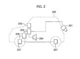
- Fig. 2 is a diagram illustrating a configuration of a vehicle that is equipped with an obstacle detection system.
- a camera 201 is mounted to the rear of the vehicle 205. This camera 201 is located with such a depression angle that the optical axis of a lens is oriented in an obliquely downward direction. A video image is taken by this camera 201 as an oblique overhead view.
- Image data which is imaged by the camera 201 is inputted into a processing unit 202 through a communication line 209.
- the processing unit 202 identifies an obstacle by means of the undermentioned image processing.
- the processing unit 202 is connected to an image display unit 203 through a signal line.
- the processing unit 202 displays various kinds of information about the obstacle, the information including an image imaged by the camera 201, and the positional relationship between the detected obstacle and the host vehicle.
- the processing unit 202 is also connected to an audio output unit 204.
- the processing unit 202 gives an alarm to a driver by use of a warning sound or a voice message.
- the processing unit 202 is connected to a brake control unit (hereinafter referred to as "BCU") 203 through a signal line.
- BCU brake control unit
- the processing unit 202 detects an obstacle in a path of the vehicle by the image processing and control logic described below, the processing unit 202 outputs an instruction signal to the BCU 203 to generate the braking force.
- the BCU 203 is connected through a signal line, a power line, or hydraulic piping to each brake 207 that is provided for each wheel of the vehicle.
- the instruction signal received from the processing unit 202 causes each brake 207 of each wheel to operate.
- the camera 201 includes a lens, an imaging element (CCD), an A/D converter, and a DSP (Digital Signal Processor).
- Image data analog signal
- the digitized image data is subjected to correction such as gamma correction by the DSP.
- the image data is then output from an output unit of the camera 201.
- other kinds of imaging elements may also be used. For example, if a CMOS sensor is adopted, a reduction in costs of the camera 201 can be achieved.
- the processing unit 202 includes: a video input unit 303 for controlling the input of image data received from the camera 201; a memory 302 for storing image data inputted from the camera, image data that has been subjected to image processing, and a program used for the image processing; a CPU 301 for performing image processing, and processing of detecting an obstacle; a video output unit 304 for controlling a signal that is inputted from the processing unit 202, and that is output to the image display unit 203; an audio output controller 305 for controlling a signal that is inputted from the processing unit 202, and that is output to the audio output unit 204; and a serial I/F 306 for controlling the output of a signal to the BCU 206. These elements can be mutually communicated through a bus 310.
- the video input unit 303 stores image data received from the camera 201 in an image area of the memory 302 in synchronization with the communication timing of the bus 310.
- the memory 302 includes at least: an image area for storing image data; and a program variable area for storing program variables that are used for the operation of the CPU 301.
- the image area is provided with a transmission area for storing an image to be output to the image display unit 203 by the video output unit 304.
- the processing unit 202 stores, in the transmission area, image data that has been subjected to the image processing.
- the obtained image data can also be displayed in the image display unit 203 just as it is by directly storing the image data inputted from the camera 201 in the transmission area of the memory 302.
- Fig. 1 is a diagram illustrating an example of the process flow in which an obstacle is detected from an image taken by the camera 201.
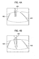
- Fig. 4 is a diagram illustrating an image that is taken by the camera 201 when there is an obstacle 401 such as a bicycle in a backward parking space.
- a step 101 two images are acquired at different timings. Therefore, when a vehicle is moving, two images are imaged at positions that differ from each other. For example, when the vehicle backs up so that the vehicle is parked in the backward parking space, if there is the obstacle 401 such as a bicycle in the parking space, two images as shown in Figs. 4A, 4B are obtained.
- Fig. 4A illustrates an image that is obtained by imaging the rear of the vehicle by the camera 201 in a certain timing
- Fig. 4B illustrates another image that is obtained thereafter by imaging the vehicle in the next timing while the vehicle 205 continuously backs up to near the obstacle 401.
- the above images are received from the camera 201 through the video input unit 303, and are then stored in the memory 302.
- the oblique overhead view which has been acquired in the step 102 is subjected to projective transformation so that the oblique overhead view is transformed into a top view.
- the projective transformation is an arithmetic operation by which a figure of an object, which is viewed from a certain direction, is transformed into a figure viewed from another direction.
- the top view is distortionless video when viewed down from a position directly above the road surface along an optical axis perpendicular to the road surface.
- the transformation from the oblique overhead view to the top view can be achieved by the projective transformation.
- a step 103 the two images, which are transformed into the top views, are subjected to positional alignment with reference to a landmark (a design, a mark, a symbol, a difference in level such as a curb) on the road surface that is imaged in common.
- the projective transformation is performed on the assumption that the image data, which has been imaged by the camera 201, is a planar design that is entirely drawn on the road surface. ' Accordingly, in actuality, even if an imaging position changes as a result of the move of the vehicle, a shape of the planar landmark on the road surface in each of the images before and after the move does not change after the projective transformation.
- an image in which a position of the vehicle is displaced by the moved distance of the vehicle on the same map will be acquired.
- a three-dimensional object is not a design on the road surface. Therefore, if the projective transformation as described above is performed, the three-dimensional object is expressed as a figure which is different from a shape of a three-dimensional object that actually exists there. An image of the three-dimensional object changes in response to a change in distance between the vehicle and the three-dimensional object, which is caused by the move of the vehicle.
- an image which is acquired by the lens includes the barrel-shaped lens distortion.
- white lines 402, 403 in Figs. 4A, 4B because of the barrel-shaped lens distortion, each line which should be actually a straight line appears to be a curve that is curved outward. Therefore, in order to correctly image the landmark on the road surface, it is necessary to eliminate the lens distortion by means of calibration.
- the calibration is performed by use of a calibration plate 801 shown in Fig. 8A.
- Black dots are regularly drawn at specified intervals in a lattice-shaped pattern on the calibration plate 801.
- the lens distortion causes each of the black dots on the calibration plate 801 to be deflected from a position at which each of the black dots should be actually located.
- a black dot which is closer to the perimeter of the image is more deflected inward.
- the lens distortion can be determined by calculating the amount of deflection in image processing.
- Fig. 8C is a diagram schematically illustrating the principles of the calibration.
- Each position of a black dot on the calibration plate shown in Fig. 8A corresponds to each lattice point shown in Fig. 8C.
- the image is corrected so that each black dot on the image in which the barrel-shaped distortion is included is adjusted to each corresponding lattice point.
- the amount of correction is measured beforehand, and is stored in the memory 203 of the processing unit 202.
- the oblique overhead views shown in Figs. 4A, 4B are transformed into the top views shown in Figs. 5A, 5B respectively.
- the above processing is performed as follows: reading out the image stored in the memory 302 to execute the processing of the image by the CPU 301; and then storing the image in the memory 302 again.
- a difference is calculated by determining the amount of the move from the landmark by use of Figs. 5A, 5B that are two top views, each of which shows backward driving.
- Figs. 5A, 5B that are two top views, each of which shows backward driving.
- the two images are aligned with each other to associate each position of the first image with each position of the second image with reference to the white lines 402, 403 as shown in Fig. 6, and then a difference in each overlapped portion is extracted.
- the white lines are detected by means of the Hough transform in this embodiment.
- the Hough transform is a general technique for detecting a straight line.
- the two images are aligned with each other using the white lines 402, 403.
- the white lines 402, 403 are detected by means of the Hough transform, there is a case where the positional alignment cannot be correctly achieved because the white lines 402, 403 parallel each other. It is because in order to associate,two planar images with each other, it is necessary to align positions of the planar images with each other vertically and horizontally, and also to align the rotation of the planar images with each other, which requires at least three reference points.
- the two images are slide along the white lines to a degree, positions of the white lines agree with each other. Accordingly, there is a case where each position of one image cannot be associated with each corresponding position of the other image.
- a straight line or a point on the road surface which are not in parallel with the two white lines, is detected.
- the detected straight line or point is used as the reference.
- the edge detection is carried out along a detected straight line to find out the end of the white line. This end is used as the reference.
- a line 411 is used as the reference. The line 411 exists over the white lines 402, 403, and does not parallel the white lines 402, 403.
- a car stop block which is placed in a parking space may also be used as the reference.
- the above description is based on the assumptions that the two images are transformed into the top views each illustrating a view from the same height, and that the distance between the two white lines is adjusted with the same scale in each top view.
- the camera 201 has a zoom function, or the like, an obstacle, a white line, and the like are imaged with the larger scale in raw image data, which is imaged by the imaging element, as the vehicle gets nearer to them. Therefore, processing of unifying the scale of a plurality of images, each of which is a target to be compared, is required.
- a mounting position and a mounting angle, at which the camera 201 is mounted to the vehicle are kept constant unless the camera 201 is shocked or unless a mounted portion is loosened.
- the camera 201 does not have a zoom function and an oscillation function. Therefore, each of images, which are imaged by the imaging element constituted of pixels, always becomes an image that is taken at a position having the constant distance and the constant direction angle with respect to the host vehicle. Accordingly, it is possible to define, on a pixel basis, the angle and the scale (magnification) for the projective transformation used to transform each image into a top view that views from the above-described specific point.
- the angle and scale for the projective transformation are calculated on a pixel basis, and are then stored in the processing unit 202 as a lookup table.
- a top view which views from the same height (the scale) is always acquired. This enables the positional alignment by use of the landmark described above.
- the size and shape of an object having no height do not change even if the position and angle of the vehicle 205 change as a result of the move of the vehicle 205.
- a shape appears to change in Fig. 4 that is the oblique overhead view before the transformation. Accordingly, as shown in Fig. 5, the change in shape is left just as it is even if the transformation into the top view is carried out. In this embodiment, a three-dimensional object is detected with attention being paid to this point.
- two images are aligned with each other before the difference in brightness in each overlapped portion is extracted. If the difference in brightness is extracted, the white lines 402, 403, and other features, disappear as shown in Fig. 7 because they agree with each other between the two images. In this case, the difference in brightness appears only in a portion of the three-dimensional object 401 having a different shape.
- an area having the difference in brightness is judged to be a three-dimensional object (obstacle).
- a three-dimensional object obstacle
- the two top views will contain some errors caused by image processing such as the projective transformation and the elimination of the barrel-shaped distortion. Therefore, instead of judging that all areas, each of which includes the difference in brightness, are three-dimensional objects, it may also be judged that an area in which a value of the difference in brightness is a specified threshold value or more is a three-dimensional object.
- an area in which the difference in brightness occurs as a result of the calculation of the difference is output as a three-dimensional object.
- the result of detecting an obstacle is displayed on a screen of the navigation monitor 203 in a superimposed manner, or sound is output to the speaker 204.
- a position at which the superimposition is carried out corresponds to an area that is the closest to the vehicle 205 among areas in which the difference in brightness occurs as a result of the calculation of the difference.
- a landmark is not found in the step 103, the positional alignment cannot be performed, which makes it impossible to detect an obstacle. Therefore, a driver is notified of this information by use of the monitor 203 or the speaker 204. In another case, a dedicated indicator is provided.
- the dedicated indicator is used to display information notifying that the processing unit 202 cannot detect a landmark. If the above processing is described with reference to the process flow shown in Fig. 3, an obstacle which has been detected in the step 103 is superimposed on an image stored in the memory 302 (processed in a superimposed manner). Then, the superimposed image is output from the video output unit 304 so as to display the superimposed image on the monitor 203.
- the output image may be a video image that is the same as the image taken by the camera as shown in Fig. 4; or the output image may also be the top view into which the image taken by the camera has been transformed as shown in Fig. 5.
- an alarm is issued from the audio output controller 305 through the speaker 204 if necessary, or the brake 207 is controlled from the brake control unit 206 through the serial interface 306 so as to reduce the speed.
- this embodiment it is so configured that if there is an object that can be obviously identified as a pattern on the road surface (for example, the white lines 402, 403), positions of two images are aligned with each other with reference to the object.
- This makes it possible to provide a configuration in which when the difference is calculated, the difference in brightness rarely occur in an area including a feature such as a road surface pattern. As a result, it is possible to prevent a road surface pattern from being identified as an obstacle by mistake.
- the difference in brightness occurs due to a parallax error of a three-dimensional object.
- the difference in brightness also appears in a moving object, for example, a walking person, a small animal such as a dog or a cat. This is because the time difference occurs if two images are imaged during the move. A position and a shape will deviate by the amount of the move for that period of time.
- a landmark cannot be detected in a certain imaging timing, even if an image is acquired in the next imaging timing, it is not possible to detect an obstacle because there is no image that is a target to be compared. For this reason, image data which has been acquired in the past, once or several times, is stored in the storing means (memory) 302 of the processing unit 202. If a landmark cannot be detected in the certain imaging timing, image data, which has been acquired last time or before the last time, is stored. Then, an obstacle is detected by comparing the stored image with an image that is acquired in the next imaging timing.
- the embodiment which uses white lines was described as a method for associating two images with each other.
- white lines are drawn on the road surface in many cases. Accordingly, it is possible to associate images with each other by using each of the white lines as a landmark.
- white lines are not drawn on the road surface. In such a case, it is necessary to find out a landmark other than the white line. An embodiment in which no white line is drawn will be described as below.
- a configuration of the vehicle 205 and that of the processing unit 202 in this embodiment are the same as those illustrated in Figs. 2, 3.
- the process flow in this embodiment is also the same as that illustrated in Fig. 1 except processing of associating each position of one image with each corresponding position of the other image.
- a closed area of the road surface surrounded by the lines (more specifically, a shape of a profile of the road surface) is defined, and the shape is used as a template. Accordingly, it is possible to align images with each other by performing pattern matching such as generalized Hough transform using the template.
- the closed area can be calculated by use of the seed fill algorithm that is a general paint routine.
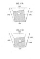
- Figs. 9A, 9B Two images which are imaged by the camera 201 become those shown in Figs. 9A, 9B. These correspond to Figs. 4A, 4B in the first embodiment.
- reference numeral 1001 denotes the road surface
- reference numerals 1002, 1003 denote right and left wall surfaces
- reference numeral 1004 denotes the end of the wall.
- the seed fill algorithm is a general paint routine that fills a closed area including a pixel corresponding to a start point with some pattern.
- Figs. 11A, 11B illustrate images in a state in which filling is completed.
- the position of the start point is assigned to a portion of the screen, which is as forward as possible, and in which there is a high possibility of the road surface. It is desirable that the position of the start point be assigned to an area that is included at least in the lower half of the imaging screen.
- the road surface has no pattern and the area thereof is sufficiently large, no closed area is found, and accordingly the pattern matching cannot also be performed. Therefore, it is necessary to judge whether or not a closed area is formed.
- the judgment as to whether or not a closed area is formed is made by checking whether or not each pixel in the leftmost line of the screen, and each pixel in the rightmost line of the screen, are filled by the seed fill algorithm.
- the pattern is fine, the pattern is broken in the smoothing stage, and consequently the variance of the brightness becomes small. Accordingly, it is possible to make the judgment by the amount of variance. Moreover, since the size is constant, besides the generalized Hough transform, a method using a normalized correlation coefficient is also effective as a template matching technique used here.
- tire stops are also located at positions that are relatively close to the road surface, and two tire stops are usually used as a set. Accordingly, as is the case with the white lines, the tire stops are easy to use as a template.
- an imaged image is subjected to the projective transformation to transform the image into a top view; and then a plurality of images are compared with one another by use of a landmark on the road surface.
- the projective transformation is performed to transform each image into not a top view, but a figure in the lateral direction, which is viewed from a direction parallel to the road surface.
- a plurality of pieces of image data are aligned with one another on the basis of a pattern located on the back wall and an outline of the wall. This method can also be adopted.
- a white line is performed. If a white line is detected, the positional alignment is performed by use of the white line. If a white line has not been detected, the process proceeds to a step 902, where a boundary line between the road surface and a three-dimensional object (for example, a wall surface) is detected. On the other hand, if a white line has been detected, a plurality of images are aligned with one another (pattern matching) by use of the boundary line in question. If the detection results in failure even in the step 902, the process proceeds to a step 903, where a texture of the road surface is detected. If a texture of the road surface has been detected, the positional alignment is performed on the basis of the texture.
- step 904 a tire stop is detected. If a tire stop has been detected, the positional alignment is performed on the basis of the tire stop. Incidentally, although not illustrated in this embodiment, it may also be so configured that the positional alignment is further tried by use of the above-described figure in the lateral direction. If the pattern matching cannot be achieved by the processing described in the steps 901 through 904, landmark-undetected processing is performed. To be more specific, a driver is notified through the image display unit 203 and the audio output unit 204 that the obstacle detection cannot be performed.
- a step 905 processing of counting the number of times a landmark is not detected is provided, and if a landmark is not detected the given number of times in succession, the landmark-undetected processing is performed.
- the specified count value is set on the basis of an imaging period of the camera 201 so that after the landmark-undetected processing, a driver can have enough time to cope with the processing. For example, it is thought that the count value is changed on the basis of the speed of the vehicle and the mounting angle of the camera (the distance from the host vehicle to an imaged area).
- the mounting angle of the camera 201 is small (the camera faces more perpendicularly to the road surface)
- an area to be imaged by the camera 201 nears the host vehicle as compared with a case where the mounting angle of the camera 201 is large. Therefore, the count value is decreased with the decrease in mounting angle.
- a position of the host vehicle is identified using map information and GPS information so as to select the algorithm that is suitable for an environment in which the host vehicle exists. For example, in parking spaces in a city area, and in parking spaces of large-scale stores including a supermarket, there is a high possibility that white lines, curbs, and car stops exist. Accordingly, higher priority may be given to the positional alignment by means of the Hough transform. In contrast with this, in parking spaces where there is a low possibility that white lines are drawn, such as a suburban parking space and a parking space in a riverbed, higher priority may be given to the positional alignment that uses the road surface texture. Furthermore, in parking spaces of stand-alone houses, or the like, it is thought that the parking spaces are surrounded by walls. Therefore, higher priority may also be given to the seed fill algorithm or the method in which each image is transformed into a figure viewed from the lateral direction.
Applications Claiming Priority (1)
| Application Number | Priority Date | Filing Date | Title |
|---|---|---|---|
| JP2006055681A JP2007235642A (ja) | 2006-03-02 | 2006-03-02 | 障害物検知システム |
Publications (2)
| Publication Number | Publication Date |
|---|---|
| EP1830321A2 true EP1830321A2 (fr) | 2007-09-05 |
| EP1830321A3 EP1830321A3 (fr) | 2010-07-07 |
Family
ID=38068349
Family Applications (1)
| Application Number | Title | Priority Date | Filing Date |
|---|---|---|---|
| EP07001423A Withdrawn EP1830321A3 (fr) | 2006-03-02 | 2007-01-23 | Système de détection d'obstacle |
Country Status (3)
| Country | Link |
|---|---|
| US (1) | US7551067B2 (fr) |
| EP (1) | EP1830321A3 (fr) |
| JP (1) | JP2007235642A (fr) |
Cited By (17)
| Publication number | Priority date | Publication date | Assignee | Title |
|---|---|---|---|---|
| WO2008104263A1 (fr) * | 2007-02-26 | 2008-09-04 | Volkswagen Aktiengesellschaft | Procédé et dispositif de détection de véhicules suivants dans un véhicule à moteur |
| WO2010060287A1 (fr) * | 2008-11-27 | 2010-06-03 | 东软集团股份有限公司 | Procédé de détection d’obstacles basé sur une vision monoculaire et dispositif associé |
| FR2945491A1 (fr) * | 2009-05-18 | 2010-11-19 | Peugeot Citroen Automobiles Sa | Procede et dispositif pour etendre une zone de visibilite |
| EP2282295A1 (fr) * | 2008-04-25 | 2011-02-09 | Hitachi Automotive Systems, Ltd. | Dispositif de reconnaissance d'objet et procédé de reconnaissance d'objet |
| WO2011047732A1 (fr) * | 2009-10-22 | 2011-04-28 | Tele Atlas B.V. | Procédé d'identification d'objets d'arrière-plan en mouvement dans une image photographique orthorectifiée |
| JP2012177569A (ja) * | 2011-02-25 | 2012-09-13 | Sankyo Eng Kk | トンネル壁面の展開画像取得システム |
| WO2012127294A1 (fr) * | 2011-03-18 | 2012-09-27 | Toyota Jidosha Kabushiki Kaisha | Système de détection de bicyclette et système de commande de rayonnement |
| CN101729792B (zh) * | 2008-10-27 | 2013-08-28 | 索尼株式会社 | 图像处理装置、图像处理方法和程序 |
| CN104115204A (zh) * | 2012-03-01 | 2014-10-22 | 日产自动车株式会社 | 立体物检测装置 |
| CN104417454A (zh) * | 2013-08-27 | 2015-03-18 | 现代自动车株式会社 | 用于检测障碍物的装置和方法 |
| US9230300B2 (en) | 2009-10-22 | 2016-01-05 | Tim Bekaert | Method for creating a mosaic image using masks |
| EP3002158A1 (fr) * | 2014-10-03 | 2016-04-06 | Delphi Technologies, Inc. | Caméra de rétroviseur dotée d'un gps pour stockage et récupération d'images |
| EP3048558A1 (fr) * | 2015-01-21 | 2016-07-27 | Application Solutions (Electronics and Vision) Ltd. | Dispositif et procédé de détection d'objet |
| CN108898684A (zh) * | 2018-05-28 | 2018-11-27 | 苏州工业园区职业技术学院 | 一种智能立体车库的管理系统 |
| CN109525810A (zh) * | 2018-11-23 | 2019-03-26 | 广州路派电子科技有限公司 | 一种高清动态3d交互式全景环视系统 |
| DE102010009620B4 (de) | 2010-02-27 | 2019-09-12 | Volkswagen Ag | Verfahren und Vorrichtung zur Detektion mindestens eines Hindernisses in einem Fahrzeugumfeld |
| GB2574697A (en) * | 2018-04-12 | 2019-12-18 | Motherson Innovations Co Ltd | Method, system and device of obtaining 3D-information of objects |
Families Citing this family (44)
| Publication number | Priority date | Publication date | Assignee | Title |
|---|---|---|---|---|
| EP1814001B1 (fr) * | 2006-01-11 | 2015-09-16 | Siemens Aktiengesellschaft | Appareil d'automatisation et procédé d'opération d'un appareil d'automatisation |
| JP2008219063A (ja) * | 2007-02-28 | 2008-09-18 | Sanyo Electric Co Ltd | 車両周辺監視装置及び方法 |
| JP2009017462A (ja) * | 2007-07-09 | 2009-01-22 | Sanyo Electric Co Ltd | 運転支援システム及び車両 |
| US7714704B1 (en) * | 2007-08-24 | 2010-05-11 | Joshua Mellen | Removable video safety system for a moving vehicle |
| US20090051514A1 (en) * | 2007-08-24 | 2009-02-26 | University Of Kuwait | Car Collision Global Positioning System |
| JP5003395B2 (ja) * | 2007-10-05 | 2012-08-15 | 日産自動車株式会社 | 車両周辺画像処理装置及び車両周辺状況提示方法 |
| JP5073461B2 (ja) * | 2007-11-29 | 2012-11-14 | クラリオン株式会社 | 車両周辺監視システム |
| JP4521642B2 (ja) * | 2008-02-13 | 2010-08-11 | 本田技研工業株式会社 | 車両周辺監視装置、車両、車両周辺監視プログラム |
| JP4902575B2 (ja) * | 2008-02-27 | 2012-03-21 | 日立オートモティブシステムズ株式会社 | 道路標示認識装置、および道路標示認識方法 |
| JP5108605B2 (ja) * | 2008-04-23 | 2012-12-26 | 三洋電機株式会社 | 運転支援システム及び車両 |
| JP2010016805A (ja) * | 2008-06-04 | 2010-01-21 | Sanyo Electric Co Ltd | 画像処理装置、運転支援システム、及び画像処理方法 |
| JP5253017B2 (ja) * | 2008-07-03 | 2013-07-31 | アルパイン株式会社 | 周辺監視装置、障害物検出方法及びコンピュータプログラム |
| WO2010044127A1 (fr) * | 2008-10-16 | 2010-04-22 | 三菱電機株式会社 | Dispositif pour détecter la hauteur d'un obstacle à l'extérieur d'un véhicule |
| JP2010208358A (ja) * | 2009-03-06 | 2010-09-24 | Toyota Industries Corp | 駐車支援装置 |
| DE102009016562A1 (de) | 2009-04-06 | 2009-11-19 | Daimler Ag | Verfahren und Vorrichtung zur Objekterkennung |
| JP5165631B2 (ja) * | 2009-04-14 | 2013-03-21 | 現代自動車株式会社 | 車両周囲画像表示システム |
| US8917929B2 (en) | 2010-03-19 | 2014-12-23 | Lapis Semiconductor Co., Ltd. | Image processing apparatus, method, program, and recording medium |
| JP5696872B2 (ja) * | 2010-03-26 | 2015-04-08 | アイシン精機株式会社 | 車両周辺監視装置 |
| IL210427A0 (en) * | 2011-01-02 | 2011-06-30 | Agent Video Intelligence Ltd | Calibration device and method for use in a surveillance system for event detection |
| JP5554261B2 (ja) * | 2011-02-24 | 2014-07-23 | アルパイン株式会社 | 立体物検出装置および立体物検出方法 |
| KR101773018B1 (ko) * | 2011-09-08 | 2017-08-30 | 인텔 코포레이션 | 이미지화된 오브젝트 특성들에 기초한 증강 현실 |
| US8848978B2 (en) * | 2011-09-16 | 2014-09-30 | Harman International (China) Holdings Co., Ltd. | Fast obstacle detection |
| US8903127B2 (en) | 2011-09-16 | 2014-12-02 | Harman International (China) Holdings Co., Ltd. | Egomotion estimation system and method |
| CN103164851B (zh) * | 2011-12-09 | 2016-04-20 | 株式会社理光 | 道路分割物检测方法和装置 |
| TWI474173B (zh) * | 2012-02-21 | 2015-02-21 | Hon Hai Prec Ind Co Ltd | 行走輔助系統及行走輔助方法 |
| US8731245B2 (en) * | 2012-03-07 | 2014-05-20 | Xerox Corporation | Multiple view transportation imaging systems |
| JP6020021B2 (ja) * | 2012-10-16 | 2016-11-02 | 株式会社デンソー | 駐車支援装置 |
| KR101393881B1 (ko) * | 2012-10-24 | 2014-05-12 | 현대자동차주식회사 | 차량의 주차구획 인식방법 |
| CN104798368B (zh) * | 2012-11-27 | 2018-08-28 | 歌乐株式会社 | 车载图像处理装置 |
| JP6178580B2 (ja) * | 2013-01-28 | 2017-08-09 | 富士通テン株式会社 | 物体検出装置、物体検出システム及び物体検出方法 |
| JP6194610B2 (ja) * | 2013-03-28 | 2017-09-13 | 富士通株式会社 | 移動距離推定装置、移動距離推定方法、及びプログラム |
| KR101439052B1 (ko) | 2013-09-05 | 2014-09-05 | 현대자동차주식회사 | 장애물 검출 장치 및 방법 |
| KR101511992B1 (ko) * | 2013-09-06 | 2015-04-14 | 현대모비스(주) | 조향 휠 제어 방법 및 이를 위한 위한 시스템 |
| US9990550B2 (en) | 2014-09-19 | 2018-06-05 | Bendix Commercial Vehicle Systems Llc | Wide baseline object detection stereo system |
| CN104299244B (zh) * | 2014-09-26 | 2017-07-25 | 东软集团股份有限公司 | 基于单目相机的障碍物检测方法及装置 |
| KR102565485B1 (ko) * | 2016-01-11 | 2023-08-14 | 한국전자통신연구원 | 도시 거리 검색 서비스 제공 서버 및 방법 |
| JP6620607B2 (ja) * | 2016-03-08 | 2019-12-18 | 富士通株式会社 | 画像解析プログラム、画像解析装置、及び画像解析方法 |
| JP6654999B2 (ja) | 2016-12-12 | 2020-02-26 | 株式会社Soken | 物標検出装置 |
| JP6838522B2 (ja) * | 2017-08-10 | 2021-03-03 | トヨタ自動車株式会社 | 画像収集システム、画像収集方法、画像収集装置、および記録媒体 |
| US11210936B2 (en) * | 2018-04-27 | 2021-12-28 | Cubic Corporation | Broadcasting details of objects at an intersection |
| KR102078984B1 (ko) * | 2018-07-20 | 2020-02-19 | 현대모비스 주식회사 | 차량의 후방영상 표시 장치 및 방법 |
| JP6734898B2 (ja) * | 2018-09-28 | 2020-08-05 | 本田技研工業株式会社 | 制御装置、制御方法及びプログラム |
| CN112907675B (zh) * | 2019-11-19 | 2022-05-24 | 浙江商汤科技开发有限公司 | 图像采集设备的标定方法、装置、系统、设备及存储介质 |
| JP7404173B2 (ja) | 2020-07-07 | 2023-12-25 | 日立Astemo株式会社 | 画像処理装置 |
Citations (1)
| Publication number | Priority date | Publication date | Assignee | Title |
|---|---|---|---|---|
| EP1094337A2 (fr) * | 1999-10-21 | 2001-04-25 | Matsushita Electric Industrial Co., Ltd. | Système d'assistance au parking |
Family Cites Families (10)
| Publication number | Priority date | Publication date | Assignee | Title |
|---|---|---|---|---|
| JP3381351B2 (ja) * | 1993-12-24 | 2003-02-24 | 日産自動車株式会社 | 車両用周囲状況表示装置 |
| JPH09139936A (ja) * | 1995-11-16 | 1997-05-27 | Nissan Motor Co Ltd | 車両用カメラ |
| JP3600378B2 (ja) * | 1996-07-24 | 2004-12-15 | 本田技研工業株式会社 | 車両の外界認識装置 |
| JPH10222679A (ja) | 1997-02-04 | 1998-08-21 | Toyota Motor Corp | 車両用画像処理装置 |
| JP3951465B2 (ja) * | 1998-06-26 | 2007-08-01 | アイシン精機株式会社 | 駐車補助装置 |
| JP3301421B2 (ja) * | 1999-10-20 | 2002-07-15 | 松下電器産業株式会社 | 車両周囲状況提示装置 |
| JP4660872B2 (ja) * | 2000-02-09 | 2011-03-30 | ソニー株式会社 | 運転支援装置及び運転支援方法 |
| JP3838884B2 (ja) * | 2001-03-29 | 2006-10-25 | 株式会社デンソー | 車両周辺表示装置、プログラムおよび記録媒体 |
| JP2003044996A (ja) * | 2001-07-31 | 2003-02-14 | Matsushita Electric Ind Co Ltd | 障害物検出装置 |
| JP2006268076A (ja) * | 2005-03-22 | 2006-10-05 | Sanyo Electric Co Ltd | 運転支援システム |
-
2006
- 2006-03-02 JP JP2006055681A patent/JP2007235642A/ja active Pending
-
2007
- 2007-01-23 EP EP07001423A patent/EP1830321A3/fr not_active Withdrawn
- 2007-01-25 US US11/657,489 patent/US7551067B2/en not_active Expired - Fee Related
Patent Citations (1)
| Publication number | Priority date | Publication date | Assignee | Title |
|---|---|---|---|---|
| EP1094337A2 (fr) * | 1999-10-21 | 2001-04-25 | Matsushita Electric Industrial Co., Ltd. | Système d'assistance au parking |
Non-Patent Citations (4)
| Title |
|---|
| BERTOZZI M; BROGGI A; FASCIOLI A: "Stereo inverse perspective mapping: theory and applications" IMAGE AND VISION COMPUTING ELSEVIER NETHERLANDS, vol. 16, no. 8, June 1998 (1998-06), pages 585-590, XP002582191 ISSN: 0262-8856 * |
| BERTOZZI M; BROGGI A; MEDICI P; PORTA P P; VITULLI R ED - FOTIADES K; SEIMENIS J: "Obstacle detection for start-inhibit and low speed driving" INTELLIGENT VEHICLES SYMPOSIUM, 2005. PROCEEDINGS. IEEE LAS VEGAS, NV, USA JUNE 6-8, 2005, 20050606 - 20050608 PISCATAWAY, NJ, USA,IEEE, PISCATAWAY, NJ, USA, 6 June 2005 (2005-06-06), pages 569-574, XP010833856 * |
| NIEMANN H; KASPRZAK W; WEIERICH P: "INTEGRATED MOTION AND GEOMETRY BASED OBSTACLE DETECTION IN IMAGE SEQUENCES OF TRAFFIC SCENES" PROCEEDINGS OF THE SPIE - THE INTERNATIONAL SOCIETY FOR OPTICAL ENGINEERING, 19960000 SPIE, PO BOX 10 BELLINGHAM WA 98227-0010 USA, vol. 2736, 8 April 1996 (1996-04-08), pages 228-239, XP008052435 ISSN: 0277-786X * |
| QIFA KE; KANADE T: "Transforming camera geometry to a virtual downward-looking camera: robust ego-motion estimation and ground-layer detection" PROCEEDINGS / 2003 IEEE COMPUTER SOCIETY CONFERENCE ON COMPUTER VISION AND PATTERN RECOGNITION, 18 - 20 JUNE 2003, MADISON, WISCONSIN; 20030618; 20030618 - 20030620 LOS ALAMITOS, CALIF. [U.A.] : IEEE COMPUTER SOCIETY, vol. 1, 18 June 2003 (2003-06-18), pages 390-397, XP010644924 * |
Cited By (30)
| Publication number | Priority date | Publication date | Assignee | Title |
|---|---|---|---|---|
| WO2008104263A1 (fr) * | 2007-02-26 | 2008-09-04 | Volkswagen Aktiengesellschaft | Procédé et dispositif de détection de véhicules suivants dans un véhicule à moteur |
| US8818026B2 (en) | 2008-04-25 | 2014-08-26 | Hitachi Automotive Systems, Ltd. | Object recognition device and object recognition method |
| EP2282295A4 (fr) * | 2008-04-25 | 2013-10-30 | Hitachi Automotive Systems Ltd | Dispositif de reconnaissance d'objet et procédé de reconnaissance d'objet |
| EP2282295A1 (fr) * | 2008-04-25 | 2011-02-09 | Hitachi Automotive Systems, Ltd. | Dispositif de reconnaissance d'objet et procédé de reconnaissance d'objet |
| CN101729792B (zh) * | 2008-10-27 | 2013-08-28 | 索尼株式会社 | 图像处理装置、图像处理方法和程序 |
| WO2010060287A1 (fr) * | 2008-11-27 | 2010-06-03 | 东软集团股份有限公司 | Procédé de détection d’obstacles basé sur une vision monoculaire et dispositif associé |
| WO2010133785A1 (fr) * | 2009-05-18 | 2010-11-25 | Peugeot Citroën Automobiles SA | Procede et dispositif pour etendre une zone de visibilite |
| CN102458923A (zh) * | 2009-05-18 | 2012-05-16 | 标致·雪铁龙汽车公司 | 用于扩展可视区域的方法和设备 |
| CN102458923B (zh) * | 2009-05-18 | 2014-12-17 | 标致·雪铁龙汽车公司 | 用于扩展可视区域的方法和设备 |
| FR2945491A1 (fr) * | 2009-05-18 | 2010-11-19 | Peugeot Citroen Automobiles Sa | Procede et dispositif pour etendre une zone de visibilite |
| US8860810B2 (en) | 2009-05-18 | 2014-10-14 | Peugeot Citroen Automobiles Sa | Method and device for extending a visibility area |
| WO2011047732A1 (fr) * | 2009-10-22 | 2011-04-28 | Tele Atlas B.V. | Procédé d'identification d'objets d'arrière-plan en mouvement dans une image photographique orthorectifiée |
| US9230300B2 (en) | 2009-10-22 | 2016-01-05 | Tim Bekaert | Method for creating a mosaic image using masks |
| DE102010009620B4 (de) | 2010-02-27 | 2019-09-12 | Volkswagen Ag | Verfahren und Vorrichtung zur Detektion mindestens eines Hindernisses in einem Fahrzeugumfeld |
| JP2012177569A (ja) * | 2011-02-25 | 2012-09-13 | Sankyo Eng Kk | トンネル壁面の展開画像取得システム |
| WO2012127294A1 (fr) * | 2011-03-18 | 2012-09-27 | Toyota Jidosha Kabushiki Kaisha | Système de détection de bicyclette et système de commande de rayonnement |
| CN104115204B (zh) * | 2012-03-01 | 2016-08-24 | 日产自动车株式会社 | 立体物检测装置 |
| EP2821981A4 (fr) * | 2012-03-01 | 2015-05-20 | Nissan Motor | Dispositif de détection d'objet en trois dimensions |
| CN104115204A (zh) * | 2012-03-01 | 2014-10-22 | 日产自动车株式会社 | 立体物检测装置 |
| CN104417454A (zh) * | 2013-08-27 | 2015-03-18 | 现代自动车株式会社 | 用于检测障碍物的装置和方法 |
| CN104417454B (zh) * | 2013-08-27 | 2018-05-15 | 现代自动车株式会社 | 用于检测障碍物的装置和方法 |
| EP3002158A1 (fr) * | 2014-10-03 | 2016-04-06 | Delphi Technologies, Inc. | Caméra de rétroviseur dotée d'un gps pour stockage et récupération d'images |
| WO2016116206A1 (fr) * | 2015-01-21 | 2016-07-28 | Application Solutions (Electronics and Vision) Ltd. | Procédé de détection d'objet et appareillage de détection d'objet |
| US10346709B2 (en) | 2015-01-21 | 2019-07-09 | Application Solutions (Electronics And Vision) Ltd | Object detecting method and object detecting apparatus |
| EP3048558A1 (fr) * | 2015-01-21 | 2016-07-27 | Application Solutions (Electronics and Vision) Ltd. | Dispositif et procédé de détection d'objet |
| GB2574697A (en) * | 2018-04-12 | 2019-12-18 | Motherson Innovations Co Ltd | Method, system and device of obtaining 3D-information of objects |
| US10733464B2 (en) | 2018-04-12 | 2020-08-04 | Motherson Innovations Company Limited | Method, system and device of obtaining 3D-information of objects |
| GB2574697B (en) * | 2018-04-12 | 2021-10-20 | Motherson Innovations Co Ltd | Method, system and device of obtaining 3D-information of objects |
| CN108898684A (zh) * | 2018-05-28 | 2018-11-27 | 苏州工业园区职业技术学院 | 一种智能立体车库的管理系统 |
| CN109525810A (zh) * | 2018-11-23 | 2019-03-26 | 广州路派电子科技有限公司 | 一种高清动态3d交互式全景环视系统 |
Also Published As
| Publication number | Publication date |
|---|---|
| JP2007235642A (ja) | 2007-09-13 |
| US20070206833A1 (en) | 2007-09-06 |
| US7551067B2 (en) | 2009-06-23 |
| EP1830321A3 (fr) | 2010-07-07 |
Similar Documents
| Publication | Publication Date | Title |
|---|---|---|
| US7551067B2 (en) | Obstacle detection system | |
| CN109435942B (zh) | 一种基于信息融合的车位线车位识别方法及装置 | |
| EP2933790B1 (fr) | Dispositif d'estimation d'angle d'attitude/emplacement d'objet mobile et procédé d'estimation d'angle d'attitude/emplacement d'objet mobile | |
| JP4832321B2 (ja) | カメラ姿勢推定装置、車両、およびカメラ姿勢推定方法 | |
| KR101143176B1 (ko) | 조감도를 이용한 주차구획 인식 방법, 장치 및 그를 이용한주차 보조 시스템 | |
| JP5089545B2 (ja) | 道路境界検出判断装置 | |
| KR101328363B1 (ko) | 차선 일탈 방지 지원 장치, 구분선 표시 방법, 프로그램 | |
| EP3140725B1 (fr) | Vue dynamique de caméra pour aider à l'attelage de remorque | |
| CN112349144B (zh) | 一种基于单目视觉的车辆碰撞预警方法及系统 | |
| US20130321629A1 (en) | Dynamic guideline overlay with image cropping | |
| WO2011039989A1 (fr) | Dispositif de surveillance des alentours d'un véhicule | |
| US20060115121A1 (en) | Abnormality detecting apparatus for imaging apparatus | |
| KR20160051993A (ko) | 운전자 지원 장치 | |
| KR20090088210A (ko) | 두 개의 기준점을 이용한 목표주차위치 검출 방법과 장치및 그를 이용한 주차 보조 시스템 | |
| CN101808236A (zh) | 车辆周边显示设备 | |
| WO2010053408A1 (fr) | Procédé et système de détermination de données de route | |
| CN104335264A (zh) | 车道划分标示检测装置、驾驶辅助系统 | |
| JP2018048949A (ja) | 物体識別装置 | |
| JP2007181129A (ja) | 車載用移動体検出装置 | |
| JP2015067030A (ja) | 運転支援装置 | |
| JP2002321579A (ja) | 警告情報生成方法及び車両側方映像生成装置 | |
| JP5083142B2 (ja) | 車両周辺監視装置 | |
| JP2007018451A (ja) | 道路区画線検出装置 | |
| US11403770B2 (en) | Road surface area detection device | |
| JP2009014645A (ja) | 車両用距離測定装置 |
Legal Events
| Date | Code | Title | Description |
|---|---|---|---|
| PUAI | Public reference made under article 153(3) epc to a published international application that has entered the european phase |
Free format text: ORIGINAL CODE: 0009012 |
|
| AK | Designated contracting states |
Kind code of ref document: A2 Designated state(s): AT BE BG CH CY CZ DE DK EE ES FI FR GB GR HU IE IS IT LI LT LU LV MC NL PL PT RO SE SI SK TR |
|
| AX | Request for extension of the european patent |
Extension state: AL BA HR MK RS |
|
| RIN1 | Information on inventor provided before grant (corrected) |
Inventor name: MONJI, TATSUHIKO Inventor name: MURAMATSU, SHOJI Inventor name: OTSUKA, YUJI |
|
| 17P | Request for examination filed |
Effective date: 20090625 |
|
| PUAL | Search report despatched |
Free format text: ORIGINAL CODE: 0009013 |
|
| RIC1 | Information provided on ipc code assigned before grant |
Ipc: G08G 1/16 20060101ALI20100518BHEP Ipc: G06T 7/00 20060101AFI20070608BHEP |
|
| AK | Designated contracting states |
Kind code of ref document: A3 Designated state(s): AT BE BG CH CY CZ DE DK EE ES FI FR GB GR HU IE IS IT LI LT LU LV MC NL PL PT RO SE SI SK TR |
|
| AX | Request for extension of the european patent |
Extension state: AL BA HR MK RS |
|
| STAA | Information on the status of an ep patent application or granted ep patent |
Free format text: STATUS: THE APPLICATION HAS BEEN WITHDRAWN |
|
| 18W | Application withdrawn |
Effective date: 20101202 |