EP1826794B1 - Device for protecting against overvoltage with solder-free contacts and corresponding manufacturing method - Google Patents
Device for protecting against overvoltage with solder-free contacts and corresponding manufacturing method Download PDFInfo
- Publication number
- EP1826794B1 EP1826794B1 EP07356029A EP07356029A EP1826794B1 EP 1826794 B1 EP1826794 B1 EP 1826794B1 EP 07356029 A EP07356029 A EP 07356029A EP 07356029 A EP07356029 A EP 07356029A EP 1826794 B1 EP1826794 B1 EP 1826794B1
- Authority
- EP
- European Patent Office
- Prior art keywords
- conducting element
- mounting
- electrically connected
- interstitial space
- conducting
- Prior art date
- Legal status (The legal status is an assumption and is not a legal conclusion. Google has not performed a legal analysis and makes no representation as to the accuracy of the status listed.)
- Not-in-force
Links
Images

Classifications
-
- H—ELECTRICITY
- H01—ELECTRIC ELEMENTS
- H01H—ELECTRIC SWITCHES; RELAYS; SELECTORS; EMERGENCY PROTECTIVE DEVICES
- H01H71/00—Details of the protective switches or relays covered by groups H01H73/00 - H01H83/00
- H01H71/02—Housings; Casings; Bases; Mountings
- H01H71/0207—Mounting or assembling the different parts of the circuit breaker
-
- H—ELECTRICITY
- H01—ELECTRIC ELEMENTS
- H01H—ELECTRIC SWITCHES; RELAYS; SELECTORS; EMERGENCY PROTECTIVE DEVICES
- H01H83/00—Protective switches, e.g. circuit-breaking switches, or protective relays operated by abnormal electrical conditions otherwise than solely by excess current
- H01H83/10—Protective switches, e.g. circuit-breaking switches, or protective relays operated by abnormal electrical conditions otherwise than solely by excess current operated by excess voltage, e.g. for lightning protection
Definitions
- the present invention relates to the general technical field of devices for protecting electrical installations and equipment against electrical overvoltages, in particular transient, and in particular due to lightning.
- Such a device is described for example in FR-A-2,846,478 .
- a switch that is constructed in a similar way is described in DE 10120677 A1 .
- the present invention also relates to a method for manufacturing a protection device of an electrical installation against overvoltages comprising at least one protection component having at least a first and a second supply terminal, at least a first and a second connection pad intended to ensure the electrical connection of the device to the electrical installation, at least a first conductive element electrically connected to the first terminal of the protection component and a second conductive element electrically connected to the first connection pad, at least a third conductive element electrically connected to the second terminal of the protection component and a fourth conductive element electrically connected to the second connection pad.
- protection devices comprise, in general, one or more overvoltage protection components, such as for example a varistor or a spark gap, provided with power supply terminals making it possible to connect them electrically to the installation to be protected.
- overvoltage protection components such as for example a varistor or a spark gap
- the protection component (s) When exposed to voltages above a predetermined threshold value, they are able to discharge a discharge current to earth while limiting the overvoltage to a value compatible with the carrying capacity of the installation and the equipment connected to it.
- surge protectors or even as " surge arresters ".
- the protective devices with an insulating housing capable of separating electrically and mechanically the internal organs of said devices, such as the protective component, the environment in which these protective devices are implemented.
- these boxes have standardized formats adapted to modular use within standard electrical panels.
- connection pads at which it is possible to make an electrical connection with a conductive element outside the housing, such as a cable or a rail.
- connection pads can be housed in the housing, be accessible from outside said housing via orifices in said housing and include a mechanical clamping system using conductive jaws able to ensure a solid locking of the junction electric, for example by screwing.
- the protection devices generally have connection elements which provide the connection between the supply terminals of the protection component or components and the connection pads.
- connection elements are in the form of a set of blades or conductive plates, preferably metal.
- said permanent junctions must be of sufficient size and quality to withstand the mechanical and thermal stresses generated by the passage of discharge currents able to flow through the protection component in the normal operation of the protective device.
- thermal assembly methods such as brazing or electrical welding, including spot welding or induction welding.
- the objects assigned to the invention are therefore intended to remedy the various drawbacks listed above and to propose a new device for protecting an electrical installation against overvoltages which is particularly simple and reliable design.
- Another object of the invention is to provide an overvoltage protection device whose manufacture is particularly inexpensive.
- Another object of the invention is to provide an overvoltage protection device whose manufacture is particularly low polluting.
- Another object of the invention is to propose a novel method of manufacturing a surge protection device which is particularly simple and inexpensive.
- the protective device 1 of an electrical installation against overvoltages according to the invention is intended to be connected bypass (or " parallel ”) on said electrical installation to be protected.
- electrical installation refers to any type of device or network powered electrically and likely to experience voltage disturbances, including transient overvoltages due to lightning.
- the protective device 1 can therefore advantageously constitute a surge arrester.
- the protection device 1 according to the invention is advantageously intended to be disposed between a phase of the installation to be protected and the earth. It is also conceivable, without departing from the scope of the invention, that the device 1, instead of being connected bypass between a phase and the earth, is connected between the neutral and the earth, between the phase and the neutral, or between two phases to achieve differential protection.
- the protection device 1 comprises at least one protective component 2 intended to be electrically connected to said electrical installation in order to protect it against overvoltages, in particular transients.
- Said protection component 2 can in particular be formed indifferently by a varistor or a spark gap.
- each protection component 2 against overvoltages is formed by a varistor, it being understood that the use of a varistor is indicated only as a preferred example and in no way constitutes a limitation of the invention.
- the protection component 2 has at least a first power supply terminal 3 and a second power supply terminal 4.
- the varistor 2 is in the form of a rectangular parallelepiped substantially flattened, the first and second supply terminal being formed by metal plates protruding from the faces of said rectangular parallelepiped.
- the protection device 1 also comprises a first connection pad 5 and a second connection pad 6, said pads being intended to ensure the electrical connection of the device to the electrical installation.
- the geometry, the dimensions and the number of constituent parts of said pads can naturally vary without departing from the scope of the invention.
- the protection device 1 comprises a housing 7 in which the protective component 2 is mounted.
- Said housing 7 will preferably be made of an insulating material and arranged to electrically and mechanically separate certain constituent elements of the device, such as that the protective component 2, the environment in which is implemented said device 1.
- the components of the protective device and protected within the housing 7 are hereinafter referred to as " internal organs ".
- said housing 7 will be particularly suitable for facilitating the handling and implementation of the device 1, while limiting the risk of short circuit or accidental electrocution related to these operations.
- the housing 7 may be formed by a first cheek 7A hollow and a second cheek 7B assembled against each other substantially in the sagittal plane of said housing 7.
- first cheek 7A serves as support for the varistor 2 and the connection pads 5, 6 without this constituting a limitation of the invention.
- connection pads 5, 6 will thus advantageously constitute electrical connection interfaces between the internal members and the electrical installation to be protected, that is to say electrical connection means between the inside and the outside. outside the housing 7.
- said pads will be housed entirely in said housing 7 and may comprise, for example, screw jaws disposed vis-à-vis orifices cut into said housing 7 to allow engagement and then holding by clamping bare wire elements or previously crimped in pods.
- parts of said connection pads could protrude from the housing 7, for example to form pins, without departing from the scope of the present invention.
- the device 1 also comprises at least one first conductive element 10 electrically connected to the first terminal 3 of the protection component 2 and a second conductive element 11 electrically connected to the first connection stud 5.
- first and second conductive elements 10, 11 are electrically connected to each other.
- the protection device 1 also comprises at least a third conductive element 12 electrically connected to the second terminal 4 of the protection component 2, and a fourth conductive element 13 electrically connected to the second connection pad 6.
- said third and fourth conductive elements 12, 13 are electrically connected to each other.
- the protection device 1 comprises a first mount 14 delimiting a first interstitial space 14 'of fixed dimension, in which at least part of the first conductive element 10 and the second element are accommodated. conductor 11, the dimension of said first interstitial space 14 'being such that said first and second conductive elements are held in contact with one another in order to ensure the electrical connection between them.
- said device 1 comprises a second frame 15 delimiting a second interstitial space 15 'of fixed dimension, within which are housed, at least partially, the third conductive element 12 and the fourth conductive element 13, the dimension of said second interstitial space being such that said third and fourth conductive elements are held in contact with each other to provide the electrical connection between them.
- the geometric, physical and functional considerations applying to the first conductive element 10, to the second conductive element 11, to the first frame 14 and to the first interstitial space 14 ', as well as to any combination of these entities are which may apply respectively to the third conductive element 12, to the fourth conductive element 13, to the second frame 15 and to the second interstitial space 15 ', and to a corresponding combination of these latter entities.
- Mount means an element or a set of elements having a housing, in the form of an " interstitial space " capable of accommodating at least partly the first and second conductive elements, respectively the third and fourth elements conductors, to provide a mechanical holding function of these conductive elements and to make an electrical connection between them.
- said frame will allow said conductor elements to be mounted so that they are kept in contact with each other, substantially immobile with respect to each other.
- Said mount will in particular provide an electrical connection between said conductive elements that is able to withstand the thermal and mechanical effects of the discharge currents that are likely to pass through the protective component 2, as well as the conductive elements 10, 11, 12, 13, when the device 1 closes overvoltages.
- said mount is preferably fixed for this purpose in connection with the housing 7.
- the first and / or second frame may comprise one or more mechanical pieces of packing, in particular distinct from the casing 7, such as jumpers, shims or spacer wedges for example.
- first frame 14 and / or the second frame 15 is integral with the housing 7, and even more preferably with the first cheek 7A. More specifically, said first and second frames 14, 15 may consist of bosses protruding from the bottom 7'A cheek 7A, said bosses having a slot or a groove preferably extending substantially in a plane normal to said bottom of the cheek to form the interstitial spaces 14 ', 15' corresponding.
- each frame will preferably comprise either a single piece or several pieces joined together in connection with each other.
- the only dimensioning of the frames, and more particularly the interstitial spaces associated with them, with respect to the dimensions and the geometry of the conductive elements to be electrically connected, makes it possible to guarantee the electrical contact of said conductive elements.
- the junction between the first conductive element 10 and the second conductive element 11 at the level of the first frame is achieved by a simple juxtaposition, preferably with overlapping, of said first and second conductive elements within the interstitial space 14 ', without resorting for example to any method of screwing, riveting, clinching, soldering or welding.
- the electrical and / or mechanical connection between the first conductive element 10 and the second conductive element 11, respectively the electrical and / or mechanical connection between the third conductive element 12 and the fourth conductive element 13, is then provided without solder or solder.
- the first conductive element (10) and the second conductive element (11) can be forcibly housed in the first frame (14).
- functional position is meant the position occupied by the conductive elements within the protective device 1 when they are housed and electrically connected in their respective frames and that they are capable of fulfilling their conduction function of the electricity between the connection pads and the power terminals.
- the design at rest of the interstitial space 14 'with respect to the resting dimensions of the first and second conductive elements 10, 11 is such that there is a mechanical interference between said conductive elements 10, 11 and the mount 14 which delimits the interstitial space 14 '.
- This interference that is to say this " negative clearance " , leads to obtaining a tight fitting, said conductive elements 10, 11 being embedded in the first frame 14 and maintained under the effect of antagonistic constraints of deformation exerting mutually between said frame and said conductive elements.
- the expression " at rest” refers to the state in which the conductive elements 10, 11 and the first frame 14 are located, before the conductive elements are inserted into the frame so as to occupy their functional position within the frame.
- the state of rest corresponds to that in which the mounts and the conductive elements are not subjected to any deformation or stress.
- the third conductive element and the fourth conductive element can be force-fitted into the second frame 15.
- the first conductive element 10 and the second conductive element 11 are adjusted substantially without constraint in the first frame 14.
- the sizing at rest of the interstitial space 14 'with respect to resting dimensions of the first and second conductive elements 10, 11 is such that there is a substantially zero clearance between said conductive elements 10, 11 and the frame 14 which defines the interstitial space 14 '.
- the third conductive element and the fourth conductive element can be adjusted substantially without stress in the second frame 15.
- satisfactory electrical contact is meant in particular an electrical connection whose electrical resistance is sufficiently low so that it does not significantly disturb the normal operation of the device 1.
- the intensity of the electric current flowing through the protection component 2 and therefore through the conductive elements 10, 11, 12, 13 is negligible, or even substantially zero.
- a discharge current caused by example by a surge related to a phenomenon of lightning, it has a high intensity but a very short duration. In either case, it is possible to tolerate that the electrical connections have a certain resistance, as long as the energy which is dissipated by the Joule effect is able to be evacuated without presenting a danger for the device 1.
- the absence of permanent current of high intensity within the device 1 allows a certain tolerance vis-à-vis the range of admissible resistance values for the links. Therefore, it is possible to use electrical connections made by simply joining the conductive elements, without seeking to bind them more intimately by a clamping force to minimize the electrical resistance that their interface presents.
- the evolution of the first variant to the second variant can be done spontaneously with the aging of the device 1, in the case where one and / or the other of the frames, initially constrained, operates progressively. creep relaxation.
- a tight assembly evolves over time towards an adjusted fitting, the deformation of the frame, and more particularly the enlargement of the interstitial space, accompanied by a loosening of the clamping pressure, up to a substantial, but acceptable, cancellation of the latter.
- the conductive elements to be connected at the frames are distinct and independent of each other prior to their mounting within the device.
- the conductive elements intended to be connected to one another have conjugate forms allowing for example their meeting by free interlocking prior to their insertion under stress.
- one or more of the conductive elements 10, 11, 12, 13 may be formed by the meeting of several parts, independent of each other or in a fixed or articulated mechanical connection.
- the first frame 14 is able to accommodate an assembly comprising a part forming the first conductive element 10 and two parts forming the second conductive element 11, one of the two parts of the second conductive element. for example acting as interposition hold, without departing from the scope of the invention.
- said conductive elements will preferably each be in the form of a single piece at their respective frames.
- the first mount 14 comprises two walls 14A, 14B extending substantially parallel to each other and delimiting the first interstitial space 14 ', the rest dimension of said first interstitial space 14' then being equal to the distance d 1 separating said walls 14A, 14B prior to insertion of the first and second conductive elements.
- the second mount 15 may comprise two walls 15A, 15B extending substantially parallel to each other and delimiting the second interstitial space 15 ', the rest dimension of said second interstitial space 15' then being equal to the distance d 2 (not shown) which separates said walls 15A, 15B before the insertion of the third and fourth conductive elements.
- said walls 14A, 14B, respectively 15A, 15B protrude from the bottom 7'A of the cheek 7A of the housing and extend substantially in planes perpendicular to said bottom 7'A.
- first conductive element 10 and the second conductive element 11 are respectively formed by a first conductive blade 16 and a second conductive blade 17, preferably metal, said blades respectively having resting thicknesses. noted e 1 and e 2 as illustrated in figure 3 .
- the third conductive element 12 and the fourth conductive element 13 are formed by a third conductive plate 18 and a fourth conductive plate 19, said blades respectively having resting thicknesses (not shown) denoted e 3 and e 4 .
- said conductive blades can be made of substantially pure copper, especially in an alloy whose copper content is greater than or equal to 99%, without having to resort to more expensive alloys like Cu-Be.
- the electrical and mechanical connection between the first conductive element 10 and the first power supply terminal 3 is preferably provided by a heat-sensitive means capable of releasing a portion of the conductive element 10 in the event of overheating of the varistor 2, so that this portion of the first conductive element 10 can then move substantially parallel to one of the main extension faces of the varistor 2, preferably in rotation, in order to isolate said varistor from the electrical installation .
- a thermal disconnection means is preferably used a first conductive blade 16 whose intrinsic elasticity will allow it to work in bending in the manner of a spring, said first blade 16 being preloaded when the first conductive element 10 is electrically connected to the first power supply terminal 3.
- the other conductive blades 17, 18 and 19 do not require a particular elasticity in this particular embodiment, the second, third and fourth conductive blades can be made of a relatively thin alloy. cheap containing more than 99% copper.
- the present invention is naturally not limited to a particular geometry of said conductive blades.
- they may have for example corrugated sections, curved, bulges, baffles, notches or salient elements without departing from the scope of the present invention.
- conductive blades will be used whose portions intended to be integrated into the frames are substantially flat and of regular thickness.
- the first interstitial space will be formed by a stepped groove in which the first and the second conductive element will overlap.
- a first conductive blade 16 and a second conductive blade 17 substantially stiffer than the first mount 14 so that the insertion of said conductive blades 16, 17 induces a deformation of said first frame 14 by wedge effect, and more precisely to produce a spacing or a crushing of the walls 14A, 14B of the latter, that is to say a widening under stress of the first interstitial space 14 '.
- the rest dimension d 1 of said first interstitial space 14 ' is preferably chosen to be substantially less than the sum e 1 + e 2 of the resting thicknesses of the first and second conductive strips.
- the rest dimension d 2 of the second interstitial space 15 ' is preferably chosen to be substantially less than the sum e 3 + e 4 of the resting thicknesses of the third and fourth conductive strips.
- the first and / or second frame may comprise a jumper having a substantially U-shaped section whose branches are likely to move apart by elastic deformation during the insertion of the first and second elements.
- the first frame 14 is formed by a housing formed directly in the first conductive element 10 or in the second conductive element 11, so that said conductive elements 10, 11 can to encase, especially under stress, directly one in the other.
- preform the second conductive blade 17 so that it has a portion of U-shaped section between the branches of which can be one end of the first conductive blade 16 is slid, or else a cylindrical geometry that makes it possible to obtain the tightening of substantially concentric conducting elements.
- the second frame 15 is integral with the third conductive element 12 or the fourth conductive element 13.
- the assembly of the first conductive element 10 with the second conductive element 11, as well as the assembly of the third conductive element 12 with the fourth conductive element 13 may advantageously have a reversible nature, in particular because the arrangement of said conductive elements allows to consider an extraction and a separation of these out of their respective mounts.
- the frames and / or the conductive elements with non-return means capable of preventing the extraction and separation of the conductive elements after they have been inserted in their respective mounts.
- non-return means capable of preventing the extraction and separation of the conductive elements after they have been inserted in their respective mounts.
- the frames themselves can be indifferently electrically insulating or conductive without departing from the scope of the invention.
- Said manufacturing method relates to a protection device 1 of an electrical installation against overvoltages comprising at least one protection component 2 having at least a first and a second supply terminal 3, 4, at least a first and a second stud 5, 6 for the electrical connection of the device 1 to the electrical installation, at least a first conductive element 10 electrically connected to the first terminal 3 of the protection component and a second conductive element 11 electrically connected to the first electrode stud. connection 5, at least one third conductive element 12 electrically connected to the second terminal 4 of the protection component and a fourth conductive element 13 electrically connected to the second connection pad 6.
- the method of manufacturing a protection device comprises a step (a) during which is inserted, at least partially, into a first interstitial space 14 'of dimension fixed by construction and delimited by a first frame 14, the first conductive element 10 and the second conductive element 11 such that said first and second conductive elements 10, 11 are held in contact with each other to provide an electrical connection between them.
- substantially flat conductive blades will be used which will be contiguous in their respective frames according to their main extension plane, in order to obtain a regular, extended and stable connection.
- step (a) comprises a substep (a 1 ) during which the first conductive element 10 and the second conductive element 11 are force-fitted into the first frame 14.
- a 1 a substep during which the first conductive element 10 and the second conductive element 11 are force-fitted into the first frame 14.
- first and second conductive blades will be chosen so that their cumulative thickness e 1 + e 2 is substantially greater than the rest spacing d 1 of the walls 14A, 14B, ie the rest dimension of the first interstitial space 14 '.
- the interposition of these blades between the walls 14A, 14B creates a wedge effect which tends to move said walls 14A, 14B away from each other, that is to say to increase the dimension of the first interstitial space 14 'to substantially match it to the cumulative thickness e 1 + e 2 of the first and second conductive blades.
- the respective thicknesses e ' 1 and e' 2 of the first and second conductive strip considered after the insertion of said blades into the first frame 14 correspond substantially to the thicknesses at rest e 1 and e 2 of said blades.
- the dimensional adaptation of the first interstitial space 14 'to the conductive elements that it receives induces a first frame deformation 14 which results in the appearance of an elastic stress which tends to oppose this deformation. and bringing the walls 14A, 14B closer, and therefore compressing the conductive strips 16, 17 against each other.
- the sub-step (a 1 ) preferably comprises a phase (a 1 ') during which the first frame 14 is elastically deformed in order to increase the dimension of the first interstitial space 14'.
- the sub-step (a 1 ) may comprise a phase (a 1 ") during which the first and / or second conductive element is deformed elastically during the insertion of said conductive elements. 10, 11 in the first mount 14.
- phase (a 1 ') and (a 1 ") can occur simultaneously or independently of each other without departing from the scope of the present invention.
- the manufacturing method of the device 1 comprises a step (b) during which is inserted, at least partially, into a second interstitial space 15 'of dimension fixed by construction and delimited by a second frame 15, the third conductive element 12 and the fourth conductive element 13 so that said third and fourth conductive elements 12, 13 are held in contact with each other in order to provide an electrical connection between them .
- step (b) may comprise a substep (b 1 ) during which the third conductive element 12 and the fourth conductive element 13 are force-fitted into the second frame 15.
- the substep (b 1 ) may comprise a phase (b 1 ') during which the second frame (15) is elastically deformed in order to increase the dimension of the second interstitial space 15'.
- the sub-step (b 1 ) may comprise a phase (b 1 ") during which the third and / or fourth conductive element is elastically deformed during the insertion of said conductive elements (12, 13) into the second frame (15).
- said manufacturing method further comprises a step (c) in which the housing 7 is made to accommodate the protection component 2 so that the first frame 14 and / or the second frame 15 have come from material with said housing 7.
- the housing will preferably be made of a thermoplastic material such as polyamide or polycarbonate, and even more preferably in a polycarbonate loaded with 20% of glass fibers.
- step (c) will comprise a substep (c 1 ) for molding a first cheek 7A.
- the first cheek 7A will have a substantially planar bottom 7'A on which we can report and fix the protective component 2 so that one of the main faces of said protection component extends parallel to said bottom 7 'AT.
- the first cheek 7A will further comprise housings forming the first and second frames 14, 15, said housing being delimited by walls integrally formed with the bottom 7'A and extending substantially, in particular at the angles of clearance by , according to planes perpendicular to said bottom 7'A.
- such an arrangement allows in particular an easy mounting of the conductive elements in their respective mount by relating them in a normal direction to the bottom 7'A, substantially identical to that which allows to place the protective component 2 in the cheek 7A.
- the housing frames 14,15 may also be grinded by machining in a step (d) after step ( C1 ) to ensure the tight fit with the conductive blades.
- steps (a) and (b) may be carried out simultaneously or one after the other.
- step (c) will preferably precede said steps (a) and (b).
- the value of the clamping force can advantageously be determined by fixing the nominal values and the respective tolerances of the rest dimension d 1 of the first interstitial space 14 'and the resting thicknesses e 1 and e 2 of the conductive blades 16, 17 depending in particular on the elasticity of the constituent materials and the geometry of the frames and the conductive elements.
- the device according to the invention advantageously has connections between conductive elements which are particularly simple to implement while allowing to achieve reliable and functional junctions, both electrical and mechanical.
- the reduction in the number of parts needed to make the electrical connections between the protection component and the installation to be protected makes it possible to reduce the cost price of said device, by limiting in particular the requirements for raw materials as well as for manufacturing and assembly.
- the particular arrangement of the various constituent elements of the device 1 within the housing 7 greatly facilitates the assembly thereof, since no complex tools or special qualifications of the operator are required.
- connection pads 5, 6 and the conductive elements 10, 11, 12, 13 makes it possible to envisage a relatively simple automation of the manufacturing process.
- the device according to the invention advantageously allows to associate an optimized manufacturing cost with high performance and reliability.
Abstract
Description
La présente invention se rapporte au domaine technique général des dispositifs de protection d'installations et d'équipements électriques contre les surtensions électriques, en particulier transitoires, et notamment dues à la foudre.The present invention relates to the general technical field of devices for protecting electrical installations and equipment against electrical overvoltages, in particular transient, and in particular due to lightning.
La présente invention concerne plus particulièrement un dispositif de protection d'une installation électrique contre les surtensions comprenant:
- au moins un composant de protection présentant au moins une première et une deuxième borne d'alimentation,
- au moins un premier et un deuxième plot de raccordement destinés à assurer le raccordement électrique du dispositif à l'installation électrique,
- au moins un premier élément conducteur relié électriquement à la première borne du composant de protection et un second élément conducteur relié électriquement au premier plot de raccordement, lesdits premier et second éléments conducteurs étant reliés électriquement l'un à l'autre,
- au moins un troisième élément conducteur relié électriquement à la deuxième borne du composant de protection et un quatrième élément conducteur relié électriquement au deuxième plot de raccordement, lesdits troisième et quatrième éléments conducteurs étant reliés électriquement l'un à l'autre.
- at least one protection component having at least a first and a second supply terminal,
- at least a first and a second connection pad intended to ensure the electrical connection of the device to the electrical installation,
- at least one first conductive element electrically connected to the first terminal of the protection component and a second conductive element electrically connected to the first connection pad, said first and second conductive elements being electrically connected to one another,
- at least one third conductive element electrically connected to the second terminal of the protection component and a fourth conductive element electrically connected to the second connection pad, said third and fourth conductive elements being electrically connected to each other.
Un tel dispositif est décrit par exemple dans
La présente invention concerne également un procédé de fabrication d'un dispositif de protection d'une installation électrique contre les surtensions comprenant au moins un composant de protection présentant au moins une première et une deuxième borne d'alimentation, au moins un premier et un deuxième plot de raccordement destinés à assurer le raccordement électrique du dispositif à l'installation électrique, au moins un premier élément conducteur relié électriquement à la première borne du composant de protection et un second élément conducteur relié électriquement au premier plot de raccordement, au moins un troisième élément conducteur relié électriquement à la deuxième borne du composant de protection et un quatrième élément conducteur relié électriquement au deuxième plot de raccordement.The present invention also relates to a method for manufacturing a protection device of an electrical installation against overvoltages comprising at least one protection component having at least a first and a second supply terminal, at least a first and a second connection pad intended to ensure the electrical connection of the device to the electrical installation, at least a first conductive element electrically connected to the first terminal of the protection component and a second conductive element electrically connected to the first connection pad, at least a third conductive element electrically connected to the second terminal of the protection component and a fourth conductive element electrically connected to the second connection pad.
Il est bien connu de recourir à des dispositifs de protection aptes à protéger les appareils électriques ou électroniques contre les surtensions pouvant par exemple résulter de phénomènes de foudre.It is well known to use protective devices capable of protecting electrical or electronic devices against overvoltages that may for example result from lightning phenomena.
Ces dispositifs de protection comportent, d'une manière générale, un ou plusieurs composants de protection contre les surtensions, tels que par exemple une varistance ou un éclateur, pourvus de bornes d'alimentation permettant de les relier électriquement à l'installation à protéger. Lorsque le ou les composants de protection sont exposés à des tensions supérieures à une valeur seuil prédéterminée, ils sont susceptibles d'écouler un courant de décharge à la terre tout en écrêtant la surtension à une valeur compatible avec la tenue de l'installation et des équipements qui y sont raccordés. De tels composants et dispositifs sont généralement désignés par le terme de « parasurtenseurs » ou encore par celui de « parafoudres ».These protection devices comprise, in general, one or more overvoltage protection components, such as for example a varistor or a spark gap, provided with power supply terminals making it possible to connect them electrically to the installation to be protected. When the protection component (s) are exposed to voltages above a predetermined threshold value, they are able to discharge a discharge current to earth while limiting the overvoltage to a value compatible with the carrying capacity of the installation and the equipment connected to it. Such components and devices are generally referred to as " surge protectors " or even as " surge arresters ".
Pour d'évidentes raisons de sécurité, en particulier afin de limiter les risques d'électrocution ou de court-circuit, il est connu de doter les dispositifs de protection d'un boîtier isolant apte à séparer électriquement et mécaniquement les organes internes desdits dispositifs, tels que le composant de protection, de l'environnement dans lequel ces dispositifs de protection sont mis en oeuvre.For obvious security reasons, in particular in order to limit the risks of electrocution or short-circuiting, it is known to provide the protective devices with an insulating housing capable of separating electrically and mechanically the internal organs of said devices, such as the protective component, the environment in which these protective devices are implemented.
Généralement, ces boîtiers possèdent des formats standardisés adaptés à une utilisation modulaire au sein de tableaux électriques normalisés.Generally, these boxes have standardized formats adapted to modular use within standard electrical panels.
Afin de pouvoir raccorder électriquement le composant de protection à l'installation électrique à protéger, il est alors nécessaire de prévoir une interface de raccordement électrique entre l'extérieur et l'intérieur du boîtier.In order to be able to electrically connect the protection component to the electrical installation to be protected, it is then necessary to provide an electrical connection interface between the outside and the inside of the housing.
Il est connu d'utiliser à cet effet des plots de raccordement au niveau desquels il est possible de réaliser une jonction électrique avec un élément conducteur extérieur au boîtier, tel qu'un câble ou un rail. En particulier, de tels plots de raccordement peuvent être logés dans le boîtier, être accessibles par l'extérieur dudit boîtier via des orifices ménagés dans ledit boîtier et comporter un système de bridage mécanique utilisant des mors conducteurs aptes à assurer un verrouillage solide de la jonction électrique, par exemple par vissage.It is known to use for this purpose connection pads at which it is possible to make an electrical connection with a conductive element outside the housing, such as a cable or a rail. In particular, such connection pads can be housed in the housing, be accessible from outside said housing via orifices in said housing and include a mechanical clamping system using conductive jaws able to ensure a solid locking of the junction electric, for example by screwing.
De plus, il est ensuite nécessaire de raccorder électriquement, à l'intérieur du boîtier, le ou les composants de protection audits plots de raccordement. A cet effet, les dispositifs de protection disposent généralement d'éléments de connexion qui assurent la liaison entre les bornes d'alimentation du ou des composants de protection et les plots de raccordement.In addition, it is then necessary to connect electrically, inside the housing, the protection component or audit pads connection. For this purpose, the protection devices generally have connection elements which provide the connection between the supply terminals of the protection component or components and the connection pads.
Généralement, ces éléments de connexion se présentent sous la forme d'un ensemble de lames ou de plaques conductrices, de préférence métalliques.Generally, these connection elements are in the form of a set of blades or conductive plates, preferably metal.
Afin de relier électriquement au sein d'un parafoudre une lame métallique à un plot de raccordement, ou encore plusieurs lames métalliques entre elles, il est connu de réaliser des jonctions permanentes, de type encastrement, à l'aide de différents procédés d'assemblage.In order to connect electrically within a lightning arrester a metal blade to a connection pad, or several metal blades together, it is known to make permanent junctions, type embedding, using different assembly methods .
Bien entendu, lesdites jonctions permanentes doivent être de dimensions et de qualité suffisantes pour supporter les contraintes mécaniques et thermiques engendrées par le passage des courants de décharge susceptibles de circuler à travers le composant de protection dans le cadre du fonctionnement normal du dispositif de protection.Of course, said permanent junctions must be of sufficient size and quality to withstand the mechanical and thermal stresses generated by the passage of discharge currents able to flow through the protection component in the normal operation of the protective device.
En particulier, il est connu de recourir à des procédés d'assemblage thermiques, tel que le brasage ou le soudage électrique, et notamment le soudage par points ou le soudage par induction.In particular, it is known to use thermal assembly methods, such as brazing or electrical welding, including spot welding or induction welding.
Bien qu'ils procurent des résultats satisfaisants quant à la tenue mécanique et électrique des jonctions vis-à-vis des courants de décharge, de tels procédés d'assemblage souffrent néanmoins d'inconvénients non négligeables.Although they provide satisfactory results as to the mechanical and electrical strength of the junctions with respect to discharge currents, such assembly methods nevertheless suffer from considerable disadvantages.
En particulier, les procédés de soudage et de brasage requièrent fréquemment des équipements et outillages complexes, onéreux et qui nécessitent une maintenance soutenue, tels que des fours tunnels ou des machines de soudage à la vague.In particular, welding and brazing processes frequently require complex and expensive equipment and tools that require sustained maintenance, such as tunnel kilns or wave soldering machines.
De plus, la mise en oeuvre de certains de ces procédés, tel que le soudage au fer, exigent l'intervention d'opérateurs hautement qualifiés. Dans ce cas, la qualité de l'assemblage est très dépendante de la dextérité de l'opérateur, et par conséquent sa reproductibilité est incertaine.In addition, the implementation of some of these methods, such as welding with iron, require the intervention of highly qualified operators. In this case, the quality of the assembly is very dependent on the dexterity of the operator, and therefore its reproducibility is uncertain.
Enfin, les opérations de soudage et de brasage impliquent fréquemment l'utilisation de substances polluantes, telles que le plomb, ou irritantes, telles que les flux de désoxydation, lesquelles substances sont potentiellement nuisibles à l'environnement comme à la santé des opérateurs et rendent obligatoires des systèmes de protection complexes et coûteux permettant l'aspiration et le traitement desdites substances.Finally, welding and brazing operations frequently involve the use of pollutants, such as lead, or irritants, such as deoxidation fluxes, which substances are potentially harmful to the environment and to the health of operators and render mandatory complex and costly protection systems for the aspiration and treatment of these substances.
Les objets assignés à l'invention visent par conséquent à porter remède aux différents inconvénients énumérés précédemment et à proposer un nouveau dispositif de protection d'une installation électrique contre les surtensions qui soit de conception particulièrement simple et fiable.The objects assigned to the invention are therefore intended to remedy the various drawbacks listed above and to propose a new device for protecting an electrical installation against overvoltages which is particularly simple and reliable design.
Un autre objet de l'invention vise à proposer un dispositif de protection contre les surtensions dont la fabrication soit particulièrement peu onéreuse.Another object of the invention is to provide an overvoltage protection device whose manufacture is particularly inexpensive.
Un autre objet de l'invention vise à proposer un dispositif de protection contre les surtensions dont la fabrication soit particulièrement peu polluante.Another object of the invention is to provide an overvoltage protection device whose manufacture is particularly low polluting.
Un autre objet de l'invention vise à proposer un nouveau procédé de fabrication d'un dispositif de protection contre les surtensions qui soit particulièrement simple et peu coûteux.Another object of the invention is to propose a novel method of manufacturing a surge protection device which is particularly simple and inexpensive.
Les objets assignés à l'invention sont atteints à l'aide d'un dispositif de protection d'une installation électrique contre les surtensions comprenant:
- au moins un composant de protection présentant au moins une première et une deuxième borne d'alimentation,
- au moins un premier et un deuxième plot de raccordement destinés à assurer le raccordement électrique du dispositif à l'installation électrique,
- au moins un premier élément conducteur relié électriquement à la première borne du composant de protection et un second élément conducteur relié électriquement au premier plot de raccordement, lesdits premier et second éléments conducteurs étant reliés électriquement l'un à l'autre,
- au moins un troisième élément conducteur relié électriquement à la deuxième borne du composant de protection et un quatrième élément conducteur relié électriquement au deuxième plot de raccordement, lesdits troisième et quatrième éléments conducteurs étant reliés électriquement l'un à l'autre,
- at least one protection component having at least a first and a second supply terminal,
- at least a first and a second connection pad intended to ensure the electrical connection of the device to the electrical installation,
- at least one first conductive element electrically connected to the first terminal of the protection component and a second conductive element electrically connected to the first connection pad, said first and second conductive elements being electrically connected to one another,
- at least one third conductive element electrically connected to the second terminal of the protection component and a fourth conductive element electrically connected to the second connection pad, said third and fourth conductive elements being electrically connected to one another,
Les objets assignés à l'invention sont également atteints à l'aide d'un procédé de fabrication d'un dispositif de protection d'une installation électrique contre les surtensions comprenant :
- au moins un composant de protection présentant au moins une première et une deuxième borne d'alimentation,
- au moins un premier et un deuxième plot de raccordement destinés à assurer le raccordement électrique du dispositif à l'installation électrique,
- au moins un premier élément conducteur relié électriquement à la première borne du composant de protection et un second élément conducteur relié électriquement au premier plot de raccordement,
- au moins un troisième élément conducteur relié électriquement à la deuxième borne du composant de protection et un quatrième élément conducteur relié électriquement au deuxième plot de raccordement
- at least one protection component having at least a first and a second supply terminal,
- at least a first and a second connection pad intended to ensure the electrical connection of the device to the electrical installation,
- at least one first conductive element electrically connected to the first terminal of the protection component and a second conductive element electrically connected to the first connection pad,
- at least one third conductive element electrically connected to the second terminal of the protection component and a fourth conductive element electrically connected to the second connection pad
D'autres particularités et avantages de l'invention apparaîtront plus en détails à la lecture de la description qui suit, ainsi qu'à l'aide des dessins annexés donnés à titre purement illustratif et non limitatif, parmi lesquels :
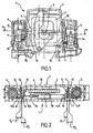
- la
figure 1 illustre selon une vue de face en coupe, un dispositif de protection conforme à l'invention. - La
figure 2 illustre, selon une vue de dessus, une coupe selon la ligne M-M du dispositif de lafigure 1 . - La
figure 3 illustre schématiquement, selon une vue de dessus partielle, simplifiée et en coupe, le montage par insertion d'un premier et d'un second élément conducteur au sein d'une première monture d'un dispositif conforme à l'invention.
- the
figure 1 illustrates according to a front view in section, a protection device according to the invention. - The
figure 2 illustrates, in a view from above, a section along the line MM of the device of thefigure 1 . - The
figure 3 illustrates schematically, in a partial top view, simplified and in section, the insertion assembly of a first and a second conductive element within a first frame of a device according to the invention.
Le dispositif de protection 1 d'une installation électrique contre les surtensions conforme à l'invention est destiné à être branché en dérivation (ou « en parallèle ») sur ladite installation électrique à protéger.The
L'expression « installation électrique » fait référence à tout type d'appareil ou réseau alimenté électriquement et susceptible de subir des perturbations de tension, notamment des surtensions transitoires dues à la foudre.The term " electrical installation " refers to any type of device or network powered electrically and likely to experience voltage disturbances, including transient overvoltages due to lightning.
Le dispositif de protection 1 peut donc avantageusement constituer un parafoudre.The
Le dispositif de protection 1 conforme à l'invention est avantageusement destiné à être disposé entre une phase de l'installation à protéger et la terre. Il est par ailleurs envisageable, sans pour autant sortir du cadre de l'invention, que le dispositif 1, au lieu d'être branché en dérivation entre une phase et la terre, soit branché entre le neutre et la terre, entre la phase et le neutre, ou encore entre deux phases pour réaliser une protection différentielle.The
Le dispositif de protection 1 conforme à l'invention comprend au moins un composant de protection 2 destiné à être relié électriquement à ladite installation électrique afin de protéger celle-ci contre les surtensions, en particulier transitoires. Ledit composant de protection 2 peut notamment être formé indifféremment par une varistance ou un éclateur. Dans la suite de la description, on considère que chaque composant de protection 2 contre les surtensions est formé par une varistance étant entendu que l'utilisation d'une varistance n'est indiquée qu'à titre d'exemple préférentiel et ne constitue en aucune manière une limitation de l'invention.The
Afin de permettre son raccordement électrique à l'installation à protéger, le composant de protection 2 présente au moins une première borne d'alimentation 3 et une deuxième borne d'alimentation 4. De préférence, la varistance 2 se présente sous la forme d'un parallélépipède rectangle sensiblement aplati, la première et la seconde borne d'alimentation pouvant être formées par des plaques métalliques faisant saillie sur des faces dudit parallélépipède rectangle.In order to allow its electrical connection to the installation to be protected, the
Le dispositif de protection 1 comprend également un premier plot de raccordement 5 et un deuxième plot de raccordement 6, lesdits plots étant destinés à assurer le raccordement électrique du dispositif à l'installation électrique. La géométrie, les dimensions et le nombre de pièces constitutives desdits plots peuvent naturellement varier sans sortir du cadre de l'invention.The
De préférence, le dispositif de protection 1 comporte un boîtier 7 au sein duquel est monté le composant de protection 2. Ledit boîtier 7 sera de préférence réalisé dans un matériau isolant et agencé de manière à séparer électriquement et mécaniquement certains éléments constitutifs du dispositif, tels que le composant de protection 2, de l'environnement dans lequel est mis en oeuvre ledit dispositif 1. Les éléments constitutifs du dispositif de protection ainsi protégés au sein du boîtier 7 sont désignés ci-après par l'expression « organes internes ».Preferably, the
Ainsi, ledit boîtier 7 sera notamment apte à faciliter la manipulation et la mise en oeuvre du dispositif 1, tout en limitant les risques de court-circuit ou d'électrocution accidentels liés à ces opérations.Thus, said housing 7 will be particularly suitable for facilitating the handling and implementation of the
En particulier, le boîtier 7 peut être formé par une première joue 7A creuse et une seconde joue 7B assemblées l'une contre l'autre sensiblement selon le plan sagittal dudit boîtier 7. Dans la suite du texte, on considèrera que la première joue 7A sert de support à la varistance 2 et aux plots de raccordement 5, 6 sans que cela ne constitue une limitation de l'invention.In particular, the housing 7 may be formed by a
Selon l'invention, les plots de raccordement 5, 6 constitueront donc avantageusement des interfaces de connexion électrique entre les organes internes et l'installation électrique à protéger, c'est-à-dire des moyens de liaison électrique entre l'intérieur et l'extérieur du boîtier 7.According to the invention, the connection pads 5, 6 will thus advantageously constitute electrical connection interfaces between the internal members and the electrical installation to be protected, that is to say electrical connection means between the inside and the outside. outside the housing 7.
De préférence, lesdits plots seront logés en totalité dans ledit boîtier 7 et pourront comporter, par exemple, des mors à vis disposés en vis-à-vis d'orifices découpés dans ledit boîtier 7 afin de permettre l'engagement puis le maintien par serrage d'éléments de câbles dénudés ou préalablement sertis dans des cosses. Bien entendu, des parties desdits plots de raccordement pourraient faire saillie hors du boîtier 7, par exemple pour former des broches, sans sortir du cadre de la présente invention.Preferably, said pads will be housed entirely in said housing 7 and may comprise, for example, screw jaws disposed vis-à-vis orifices cut into said housing 7 to allow engagement and then holding by clamping bare wire elements or previously crimped in pods. Of course, parts of said connection pads could protrude from the housing 7, for example to form pins, without departing from the scope of the present invention.
Le dispositif 1 conforme à l'invention comprend également au moins un premier élément conducteur 10 relié électriquement à la première borne 3 du composant de protection 2 ainsi qu'un second élément conducteur 11 relié électriquement au premier plot de raccordement 5. Afin d'assurer le raccordement électrique de la première borne 3 du composant de protection 2 au premier plot de raccordement 5, lesdits premier et second éléments conducteurs 10,11 sont reliés électriquement l'un à l'autre.The
En outre, le dispositif de protection 1 conforme à l'invention comprend également au moins un troisième élément conducteur 12 relié électriquement à la deuxième borne 4 du composant de protection 2, ainsi qu'un quatrième élément conducteur 13 relié électriquement au deuxième plot de raccordement 6. Afin d'assurer le raccordement électrique de ladite deuxième borne 4 audit plot de raccordement 6, lesdits troisième et quatrième éléments conducteurs 12, 13 sont reliés électriquement l'un à l'autre.In addition, the
Selon une caractéristique importante de l'invention, le dispositif de protection 1 comporte une première monture 14 délimitant un premier espace interstitiel 14' de dimension fixée par construction au sein duquel sont logés, au moins partiellement, le premier élément conducteur 10 et le second élément conducteur 11, la dimension dudit premier espace interstitiel 14' étant telle que lesdits premier et second éléments conducteurs sont maintenus au contact l'un de l'autre afin d'assurer la liaison électrique entre eux.According to an important characteristic of the invention, the
Selon une autre caractéristique importante de l'invention, ledit dispositif 1 comporte une deuxième monture 15 délimitant un second espace interstitiel 15' de dimension fixée par construction au sein duquel sont logés, au moins partiellement, le troisième élément conducteur 12 et le quatrième élément conducteur 13, la dimension dudit second espace interstitiel étant telle que lesdits troisième et quatrième éléments conducteurs sont maintenus au contact l'un de l'autre afin d'assurer la liaison électrique entre eux.According to another important characteristic of the invention, said
Dans ce qui suit, les considérations géométriques, physiques et fonctionnelles s'appliquant au premier élément conducteur 10, au deuxième élément conducteur 11, à la première monture 14 et au premier espace interstitiel 14', ainsi qu'à une combinaison quelconque de ces entités, sont susceptibles de s'appliquer respectivement au troisième élément conducteur 12, au quatrième élément conducteur 13, à la deuxième monture 15 et au second espace interstitiel 15', ainsi qu'à une combinaison correspondante de ces dernières entités.In the following, the geometric, physical and functional considerations applying to the first
Par « monture », on désigne un élément ou un ensemble d'éléments présentant un logement, sous forme d'un « espace interstitiel » apte à accueillir au moins en partie le premier et le second éléments conducteurs, respectivement le troisième et le quatrième éléments conducteurs, à assurer une fonction de maintien mécanique de ces éléments conducteurs et à réaliser une jonction électrique entre eux. De préférence, ladite monture permettra un montage desdits éléments conducteurs de telle sorte que ceux-ci soient maintenus au contact l'un de l'autre, sensiblement immobiles l'un par rapport à l'autre." Mount " means an element or a set of elements having a housing, in the form of an " interstitial space " capable of accommodating at least partly the first and second conductive elements, respectively the third and fourth elements conductors, to provide a mechanical holding function of these conductive elements and to make an electrical connection between them. Preferably, said frame will allow said conductor elements to be mounted so that they are kept in contact with each other, substantially immobile with respect to each other.
Ladite monture permettra notamment d'assurer une liaison électrique entre lesdits éléments conducteurs qui soit capable de résister aux effets thermiques et mécaniques des courants de décharge qui sont susceptibles de traverser le composant de protection 2, ainsi que les éléments conducteurs 10, 11, 12, 13, lorsque le dispositif 1 écrête des surtensions. En particulier, ladite monture sera de préférence fixée à cet effet en liaison encastrement avec le boîtier 7.Said mount will in particular provide an electrical connection between said conductive elements that is able to withstand the thermal and mechanical effects of the discharge currents that are likely to pass through the
Selon une variante de réalisation, la première et/ou la deuxième monture peut comporter une ou plusieurs pièces mécaniques de garniture, notamment distinctes du boîtier 7, telles que des cavaliers, des cales d'épaisseur ou des coins écarteurs par exemple.According to an alternative embodiment, the first and / or second frame may comprise one or more mechanical pieces of packing, in particular distinct from the casing 7, such as jumpers, shims or spacer wedges for example.
Toutefois, selon une variante de réalisation préférentielle, la première monture 14 et/ou la deuxième monture 15 est venue de matière avec le boîtier 7, et de façon encore plus préférentielle avec la première joue 7A. Plus précisément, lesdites première et deuxième montures 14, 15 peuvent êtres constituées par des bossages faisant saillie à partir du fond 7'A de la joue 7A, lesdits bossages présentant une fente ou une rainure s'étendant de préférence sensiblement dans un plan normal audit fond de la joue afin de former les espaces interstitiels 14', 15' correspondants.However, according to a preferred embodiment, the
Par l'expression « de dimension fixée par construction », on indique que les espaces interstitiels (14', 15') sont de dimension finie et déterminée par une géométrie établie des montures (14, 15), notamment établie préalablement à la mise en place des éléments conducteurs. Ainsi, afin de définir les limites de son espace interstitiel, chaque monture comportera de préférence soit une pièce unique soit plusieurs pièces réunies en liaison encastrement les unes par rapport aux autres.By the expression " of dimension fixed by construction ", it is indicated that the interstitial spaces (14 ', 15') are of finite dimension and determined by an established geometry of the frames (14, 15), in particular established prior to the implementation of place conductive elements. Thus, in order to define the limits of its interstitial space, each frame will preferably comprise either a single piece or several pieces joined together in connection with each other.
Selon l'invention, le seul dimensionnement des montures, et plus particulièrement des espaces interstitiels qui leurs sont associés, par rapport aux dimensions et à la géométrie des éléments conducteurs à relier électriquement, permet de garantir la mise au contact électrique desdits éléments conducteurs.According to the invention, the only dimensioning of the frames, and more particularly the interstitial spaces associated with them, with respect to the dimensions and the geometry of the conductive elements to be electrically connected, makes it possible to guarantee the electrical contact of said conductive elements.
Ainsi, de façon particulièrement préférentielle, la jonction entre le premier élément conducteur 10 et le second élément conducteur 11 au niveau de la première monture est réalisé par une simple juxtaposition, de préférence avec chevauchement, desdits premier et deuxième éléments conducteurs au sein de l'espace interstitiel 14', sans recourir par exemple à aucun procédé de vissage, de rivetage, de clinchage, de brasage, ni de soudage.Thus, particularly preferably, the junction between the first
En particulier, la liaison électrique et/ou mécanique entre le premier élément conducteur 10 et le second élément conducteur 11, respectivement la liaison électrique et/ou mécanique entre le troisième élément conducteur 12 et le quatrième élément conducteur 13, est alors assurée sans brasure ni soudure.In particular, the electrical and / or mechanical connection between the first
De façon particulièrement préférentielle, aucun moyen auxiliaire de serrage ou de renforcement n'est nécessaire pour assurer la bonne tenue de la liaison électrique et/ou mécanique ainsi réalisée.In a particularly preferred manner, no auxiliary means of clamping or reinforcement is necessary to ensure the good strength of the electrical and / or mechanical connection thus produced.
Selon une première forme de réalisation, le premier élément conducteur (10) et le second élément conducteur (11) peuvent être logés à force dans la première monture (14).According to a first embodiment, the first conductive element (10) and the second conductive element (11) can be forcibly housed in the first frame (14).
Par l'expression « logés à force », on indique que l'opération de mise en place des éléments conducteurs dans leurs montures respectives, et plus précisément au sein des espaces interstitiels correspondants, requiert l'application d'un effort mécanique significatif, ledit effort permettant de forcer la déformation des montures et/ou des éléments conducteurs de telle sorte qu'une fois lesdits éléments conducteurs installés en position fonctionnelle dans les montures, lesdits éléments conducteurs sont maintenus au contact l'un de l'autre par une contrainte élastique résiduelle qui se traduit notamment par une pression de serrage.By the expression " forcibly housed ", it is indicated that the operation of placing the conductive elements in their respective mounts, and more precisely within the corresponding interstitial spaces, requires the application of a significant mechanical force, said force to force the deformation of the frames and / or conductive elements so that once said conductive elements are installed in operative position in the frames, said conductive elements are held in contact with each other by an elastic stress residual which results in particular by a clamping pressure.
Par « position fonctionnelle », on désigne la position qu'occupent les éléments conducteurs au sein du dispositif de protection 1 lorsqu'ils sont logés et reliés électriquement dans leurs montures respectives et qu'ils sont aptes à remplir leur fonction de conduction de l'électricité entre les plots de raccordement et les bornes d'alimentation.By " functional position " is meant the position occupied by the conductive elements within the
Ainsi, selon cette première forme de réalisation, le dimensionnement au repos de l'espace interstitiel 14' par rapport aux dimensions au repos des premier et second éléments conducteurs 10, 11 est tel qu'il existe une interférence mécanique entre lesdits éléments conducteurs 10, 11 et la monture 14 qui délimite l'espace interstitiel 14'. Cette interférence, c'est-à-dire ce « jeu négatif », conduit à l'obtention d'un montage serré, lesdits éléments conducteurs 10, 11 étant enchâssés dans la première monture 14 et maintenus sous l'effet de contraintes antagonistes de déformation s'exerçant mutuellement entre ladite monture et lesdits éléments conducteurs.Thus, according to this first embodiment, the design at rest of the interstitial space 14 'with respect to the resting dimensions of the first and second
En d'autres termes, il apparaît une pression de serrage résultant de l'insertion dans la monture 14 des deux éléments conducteurs 10,11 dont l'encombrement global au repos excède sensiblement l'espace interstitiel 14' disponible au repos, c'est-à-dire excède la capacité d'accueil au repos de la monture.In other words, it appears a clamping pressure resulting from the insertion into the
L'expression « au repos » fait référence à l'état dans lequel se trouvent les éléments conducteurs 10, 11, respectivement la première monture 14, avant que les éléments conducteurs ne soient insérés dans la monture de manière à occuper leur position fonctionnelle au sein du dispositif de protection 1. En d'autres termes, l'état de repos correspond à celui dans lequel les montures et les éléments conducteurs ne sont soumis à aucune déformation ni contrainte.The expression " at rest " refers to the state in which the
De façon analogue et indépendante, le troisième élément conducteur et le quatrième élément conducteur peuvent être logés à force dans la deuxième monture 15.In a similar and independent manner, the third conductive element and the fourth conductive element can be force-fitted into the
Selon une deuxième forme de réalisation, le premier élément conducteur 10 et le second élément conducteur 11 sont ajustés sensiblement sans contrainte dans la première monture 14.According to a second embodiment, the first
En d'autres termes, dans cette deuxième forme de réalisation, le dimensionnement au repos de l'espace interstitiel 14' par rapport aux dimensions au repos des premier et second éléments conducteurs 10, 11 est tel qu'il existe un jeu sensiblement nul entre lesdits éléments conducteurs 10, 11 et la monture 14 qui délimite l'espace interstitiel 14'.In other words, in this second embodiment, the sizing at rest of the interstitial space 14 'with respect to resting dimensions of the first and second
De même, le troisième élément conducteur et le quatrième élément conducteur peuvent être ajustés sensiblement sans contrainte dans la deuxième monture 15.Similarly, the third conductive element and the fourth conductive element can be adjusted substantially without stress in the
De façon remarquable, il est possible de maintenir un contact électrique satisfaisant entre le premier et le second élément conducteur, respectivement entre le troisième et le quatrième élément conducteur, en limitant le débattement relatif desdits éléments conducteurs par un simple guidage précis de ceux-ci au sein de leurs montures respectives mais sans réaliser de serrage. Par « contact électrique satisfaisant » on désigne notamment une liaison électrique dont la résistance électrique est suffisamment faible pour qu'elle ne perturbe pas significativement le fonctionnement normal du dispositif 1.Remarkably, it is possible to maintain a satisfactory electrical contact between the first and the second conductive element, respectively between the third and the fourth conductive element, by limiting the relative movement of said conductive elements by a simple precise guidance thereof to within their respective mounts but without making any tightening. By " satisfactory electrical contact " is meant in particular an electrical connection whose electrical resistance is sufficiently low so that it does not significantly disturb the normal operation of the
En effet, lorsqu'un courant électrique circule à travers le composant de protection 2, et par conséquent à travers les éléments conducteurs 10, 11, 12, 13 et leurs liaisons respectives, lesdits éléments conducteurs et lesdites liaisons, qui possèdent une résistance électrique intrinsèque non nulle, même si celle-ci est faible, sont susceptibles de s'échauffer par effet Joule.Indeed, when an electric current flows through the
Toutefois, lors du fonctionnement normal du dispositif de protection 1 et en l'absence de phénomène de surtension, l'intensité du courant électrique qui circule à travers le composant de protection 2 et par conséquent à travers les éléments conducteurs 10, 11, 12, 13 est négligeable, voire sensiblement nulle. De plus, lors de l'écoulement d'un courant de décharge provoqué par exemple par une surtension liée à un phénomène de foudre, celui-ci présente une forte intensité mais une durée très brève. Dans l'un et l'autre cas, il est possible de tolérer que les liaisons électriques présentent une certaine résistance, tant que l'énergie qui s'y trouve dissipée par effet Joule est à même d'être évacuée sans présenter de danger pour le dispositif 1.However, during normal operation of the
Ainsi, l'absence de courant permanent d'intensité élevée au sein du dispositif 1 autorise une certaine tolérance vis-à-vis de la plage de valeurs de résistance admissible pour les liaisons. Par conséquent, il est possible d'utiliser des liaisons électriques réalisées par un simple accolement des éléments conducteurs, sans chercher à lier ceux-ci plus intimement par un effort de serrage destiné à minimiser la résistance électrique que présente leur interface.Thus, the absence of permanent current of high intensity within the
Bien entendu, il est envisageable, sans sortir du cadre de l'invention, de réaliser un dispositif 1 combinant les deux formes de réalisation décrites plus haut, par exemple en logeant à force les premier et second éléments conducteurs 10, 11 dans la première monture 14 et en ajustant sensiblement sans contrainte les troisième et quatrième éléments conducteurs 12, 13 dans la seconde monture 15, ou inversement.Of course, it is conceivable, without departing from the scope of the invention, to provide a
Par ailleurs, il est remarquable que l'évolution de la première variante à la deuxième variante peut se faire spontanément avec le vieillissement du dispositif 1, dans le cas où l'une et/ou l'autre des montures, initialement contrainte, opère progressivement une relaxation par fluage. En d'autres termes, il est envisageable qu'un montage serré évolue avec le temps vers un montage ajusté, la déformation de la monture, et plus particulièrement l'agrandissement de l'espace interstitiel, s'accompagnant d'un relâchement de la pression de serrage, à concurrence d'une annulation sensible, mais acceptable, de cette dernière.Moreover, it is remarkable that the evolution of the first variant to the second variant can be done spontaneously with the aging of the
Selon une variante de réalisation préférentielle, les éléments conducteurs à relier au niveau des montures sont distincts et indépendants les uns des autres préalablement à leur montage au sein du dispositif.According to a preferred embodiment, the conductive elements to be connected at the frames are distinct and independent of each other prior to their mounting within the device.
En outre, il est envisageable que les éléments conducteurs destinés à être reliés l'un à l'autre présentent des formes conjuguées permettant par exemple leur réunion par emboîtement libre en préalable à leur insertion sous contrainte.In addition, it is conceivable that the conductive elements intended to be connected to one another have conjugate forms allowing for example their meeting by free interlocking prior to their insertion under stress.
Selon une variante de réalisation, un ou plusieurs des éléments conducteurs 10, 11, 12, 13 peuvent être formés par la réunion de plusieurs pièces, indépendantes les unes des autres ou en liaison mécanique fixe ou articulée. A titre illustratif et non limitatif, il est envisageable que la première monture 14 soit apte à accueillir un ensemble comprenant une pièce formant le premier élément conducteur 10 et deux pièces formant le second élément conducteur 11, l'une des deux pièces du second élément conducteur faisant par exemple office de cale d'interposition, sans sortir du cadre de l'invention.According to an alternative embodiment, one or more of the
Toutefois, lesdits éléments conducteurs se présenteront de préférence chacun sous la forme d'une pièce unique au niveau de leurs montures respectives.However, said conductive elements will preferably each be in the form of a single piece at their respective frames.
Selon une variante de réalisation préférentielle illustrée à la
De manière analogue, la deuxième monture 15 peut comporter deux parois 15A, 15B s'étendant sensiblement parallèlement l'une à l'autre et délimitant le second espace interstitiel 15', la dimension au repos dudit second espace interstitiel 15' étant alors égale à la distance d2 (non représentée) qui sépare lesdites parois 15A, 15B avant l'insertion des troisième et quatrième éléments conducteurs.Similarly, the
De façon encore plus préférentielle, lesdites parois 14A, 14B, respectivement 15A, 15B font saillie depuis le fond 7'A de la joue 7A du boîtier et s'étendent sensiblement selon des plans perpendiculaires audit fond 7'A.Even more preferably, said
Par ailleurs, selon une variante de réalisation préférentielle, le premier élément conducteur 10 et le second élément conducteur 11 sont formés respectivement par une première lame conductrice 16 et par une seconde lame conductrice 17, de préférence métalliques, lesdites lames présentant respectivement des épaisseurs au repos notées e1 et e2 tel que cela est illustré à la
De même, selon une variante de réalisation préférentielle, le troisième élément conducteur 12 et le quatrième élément conducteur 13 sont formés par une troisième lame conductrice 18 et une quatrième lame conductrice 19, lesdites lames présentant respectivement des épaisseurs au repos (non représentées) notées e3 et e4.Similarly, according to a preferred embodiment, the third
De façon particulièrement avantageuse, lorsqu'elles n'ont pas besoin de présenter un caractère élastique particulier, lesdites lames conductrices peuvent être fabriquées en cuivre sensiblement pur, notamment dans un alliage dont la teneur en cuivre est supérieure ou égale à 99%, sans avoir à recourir à des alliages plus coûteux comme le Cu-Be.Particularly advantageously, when they do not need to have a particular elastic nature, said conductive blades can be made of substantially pure copper, especially in an alloy whose copper content is greater than or equal to 99%, without having to resort to more expensive alloys like Cu-Be.
Par exemple, dans la variante de réalisation illustrée à la
La présente invention n'est naturellement pas limitée à une géométrie particulière desdites lames conductrices. En particulier, celles-ci pourront présenter par exemple des sections ondulées, recourbées, des renflements, des chicanes, des encoches ou des éléments saillants sans sortir du cadre de la présente invention.The present invention is naturally not limited to a particular geometry of said conductive blades. In particular, they may have for example corrugated sections, curved, bulges, baffles, notches or salient elements without departing from the scope of the present invention.
Toutefois, dans une variante de réalisation préférentielle, on utilisera des lames conductrices dont les portions destinées à être intégrées dans les montures sont sensiblement planes et d'épaisseur régulière.However, in a preferred embodiment, conductive blades will be used whose portions intended to be integrated into the frames are substantially flat and of regular thickness.
Selon une variante de réalisation préférentielle illustrée aux
De façon analogue, la dimension au repos d2 du second espace interstitiel 15' est de préférence choisie sensiblement inférieure à la somme e3 + e4 des épaisseurs au repos de la troisième et de la quatrième lames conductrices.Similarly, the rest dimension d 2 of the second interstitial space 15 'is preferably chosen to be substantially less than the sum e 3 + e 4 of the resting thicknesses of the third and fourth conductive strips.
Selon une variante de réalisation non représentée, la première et/ou la deuxième monture peut comporter un cavalier présentant une section sensiblement en forme de U dont les branches sont susceptibles de s'écarter par déformation élastique lors de l'insertion des premier et second éléments conducteurs 10, 11, respectivement des troisième et quatrième éléments conducteurs 12, 13.According to an alternative embodiment not shown, the first and / or second frame may comprise a jumper having a substantially U-shaped section whose branches are likely to move apart by elastic deformation during the insertion of the first and second elements.
Selon une autre variante de réalisation non représentée, il est envisageable que la première monture 14 soit formée par un logement ménagé directement dans le premier élément conducteur 10 ou dans le second élément conducteur 11, de telle sorte que lesdits éléments conducteurs 10, 11 puissent s'emboîter, notamment sous contrainte, directement l'un dans l'autre. En particulier, on peut envisager de préformer la deuxième lame conductrice 17 de manière à ce qu'elle présente une portion de section en forme de U entre les branches de laquelle peut être glissée une extrémité de la première lame conductrice 16, ou encore de mettre en oeuvre une géométrie cylindrique permettant d'obtenir le serrage d'éléments conducteurs sensiblement concentriques.According to another variant of embodiment not shown, it is conceivable that the
De manière analogue, il est envisageable que la seconde monture 15 soit venue de matière avec le troisième élément conducteur 12 ou le quatrième élément conducteur 13.Similarly, it is conceivable that the
Sur la variante de réalisation illustrée aux
Toutefois, selon une variante de réalisation non représentée, il est parfaitement envisageable de doter les montures et/ou les éléments conducteurs de moyens anti-retour aptes à empêcher l'extraction et la séparation des éléments conducteurs après que ceux-ci ont été insérés dans leurs montures respectives. En particulier, on pourra réaliser des ergots ou des dépressions dans les éléments conducteurs, par exemple par poinçonnage, lesdits ergots ou dépressions coopérant alors avec des encoches ou des languettes disposées à cet effet dans la monture, notamment au niveau des parois délimitant l'entrefer.However, according to an alternative embodiment not shown, it is perfectly conceivable to provide the frames and / or the conductive elements with non-return means capable of preventing the extraction and separation of the conductive elements after they have been inserted in their respective mounts. In particular, it will be possible to make lugs or depressions in the conductive elements, for example by punching, said lugs or depressions then cooperating with notches or tabs arranged for this purpose in the frame, particularly at the walls delimiting the gap .
Enfin, les montures en elles-mêmes peuvent être indifféremment électriquement isolantes ou conductrices sans sortir du cadre de l'invention.Finally, the frames themselves can be indifferently electrically insulating or conductive without departing from the scope of the invention.
Le procédé de fabrication d'une variante préférentielle du dispositif de protection 1 conforme à l'invention va maintenant être décrit.The method of manufacturing a preferred variant of the
Ledit procédé de fabrication concerne un dispositif de protection 1 d'une installation électrique contre les surtensions comprenant au moins un composant de protection 2 présentant au moins une première et une deuxième borne d'alimentation 3, 4, au moins un premier et un deuxième plot de raccordement 5, 6 destinés à assurer le raccordement électrique du dispositif 1 à l'installation électrique, au moins un premier élément conducteur 10 relié électriquement à la première borne 3 du composant de protection et un second élément conducteur 11 relié électriquement au premier plot de raccordement 5, au moins un troisième élément conducteur 12 relié électriquement à la deuxième borne 4 du composant de protection et un quatrième élément conducteur 13 relié électriquement au deuxième plot de raccordement 6.Said manufacturing method relates to a
Le procédé de fabrication d'un dispositif de protection conforme à l'invention comprend une étape (a) au cours de laquelle on insère, au moins partiellement, dans un premier espace interstitiel 14' de dimension fixée par construction et délimité par une première monture 14, le premier élément conducteur 10 et le second élément conducteur 11 de telle sorte que lesdits premier et second éléments conducteurs 10, 11 soient maintenus au contact l'un de l'autre afin d'assurer une liaison électrique entre eux.The method of manufacturing a protection device according to the invention comprises a step (a) during which is inserted, at least partially, into a first interstitial space 14 'of dimension fixed by construction and delimited by a
Plus particulièrement, on utilisera de préférence des lames conductrices sensiblement planes que l'on accolera dans leurs montures respectives selon leur plan d'extension principal, afin d'obtenir une liaison régulière, étendue et stable.More particularly, preferably substantially flat conductive blades will be used which will be contiguous in their respective frames according to their main extension plane, in order to obtain a regular, extended and stable connection.
Ainsi que cela est illustré à la
Afin de faire pénétrer les lames 16, 17 entre les parois 14A, 14B, on exerce sur celles-ci un effort de pénétration F qui tend à les enfoncer dans la monture 14, sensiblement en direction du fond 7'A sur la
De façon préférentielle, l'étape (a) comprend une sous-étape (a1) au cours de laquelle on insère à force le premier élément conducteur 10 et le second élément conducteur 11 dans la première monture 14. Ainsi, on réalisera un montage serré.Preferably, step (a) comprises a substep (a 1 ) during which the first
A cette fin, on choisira les première et deuxième lames conductrices de telle sorte que leur épaisseur cumulée e1 + e2 soit sensiblement supérieure à l'écartement au repos d1 des parois 14A, 14B, c'est-à-dire à la dimension au repos du premier espace interstitiel 14'.For this purpose, the first and second conductive blades will be chosen so that their cumulative thickness e 1 + e 2 is substantially greater than the rest spacing d 1 of the
Dans le cas préférentiel où les lames conductrices sont plus rigides que la monture 14, l'interposition de ces lames entre les parois 14A, 14B crée un effet de coin qui tend à écarter lesdites parois 14A, 14B l'une de l'autre, c'est-à-dire à augmenter la dimension du premier espace interstitiel 14' pour faire correspondre sensiblement celle-ci à l'épaisseur cumulée e1 + e2 de la première et de la deuxième lames conductrices. En d'autres termes, ainsi que cela est illustré à la
Selon l'invention, l'adaptation dimensionnelle du premier espace interstitiel 14' aux éléments conducteurs qu'il accueille induit une déformation de première monture 14 qui se traduit par l'apparition d'une contrainte élastique qui tend à s'opposer à cette déformation et à rapprocher les parois 14A, 14B, et par conséquent à comprimer les lames conductrices 16, 17 l'une contre l'autre.According to the invention, the dimensional adaptation of the first interstitial space 14 'to the conductive elements that it receives induces a
Ainsi, la sous-étape (a1) comprend de préférence une phase (a1') au cours de laquelle on déforme élastiquement la première monture 14 afin d'augmenter la dimension du premier espace interstitiel 14'.Thus, the sub-step (a 1 ) preferably comprises a phase (a 1 ') during which the
Selon une variante de réalisation, il est envisageable de réaliser la déformation de la première monture 14 préalablement à l'insertion des éléments conducteurs 10, 11, par exemple à l'aide d'un coin écarteur, puis d'insérer librement les éléments conducteurs entre les parois 14A, 14B avant de libérer lesdites parois pour permettre à celles-ci d'opérer un retour élastique et de venir comprimer lesdits éléments conducteurs, par exemple en retirant ledit coin.According to an alternative embodiment, it is conceivable to perform the deformation of the
Par ailleurs, selon une variante de réalisation, la sous-étape (a1) peut comprendre une phase (a1") au cours de laquelle on déforme élastiquement le premier et/ou le second élément conducteur lors de l'insertion desdits éléments conducteurs 10, 11 dans la première monture 14.Furthermore, according to an alternative embodiment, the sub-step (a 1 ) may comprise a phase (a 1 ") during which the first and / or second conductive element is deformed elastically during the insertion of said conductive elements. 10, 11 in the
Bien entendu, les phases (a1') et (a1") peuvent intervenir simultanément ou indépendamment l'une de l'autre sans sortir du cadre de la présente invention.Of course, the phases (a 1 ') and (a 1 ") can occur simultaneously or independently of each other without departing from the scope of the present invention.
Par ailleurs, selon une caractéristique importante de l'invention, le procédé de fabrication du dispositif 1 comprend une étape (b) au cours de laquelle on insère, au moins partiellement, dans un second espace interstitiel 15' de dimension fixée par construction et délimité par une deuxième monture 15, le troisième élément conducteur 12 et le quatrième élément conducteur 13 de telle sorte que lesdits troisième et quatrième éléments conducteurs 12, 13 soient maintenus au contact l'un de l'autre afin d'assurer une liaison électrique entre eux.Furthermore, according to an important characteristic of the invention, the manufacturing method of the
De manière analogue à ce qui a été décrit précédemment, l'étape (b) peut comprendre une sous-étape (b1) au cours de laquelle on insère à force le troisième élément conducteur 12 et le quatrième élément conducteur 13 dans la deuxième monture 15.In a manner analogous to what has been described above, step (b) may comprise a substep (b 1 ) during which the third
De même, la sous-étape (b1) peut comprendre une phase (b1') au cours de laquelle on déforme élastiquement la deuxième monture (15) afin d'augmenter la dimension du second espace interstitiel 15'.Similarly, the substep (b 1 ) may comprise a phase (b 1 ') during which the second frame (15) is elastically deformed in order to increase the dimension of the second interstitial space 15'.
En particulier, ainsi que cela est illustré à la
De même, la sous-étape (b1) peut comprendre une phase (b1") au cours de laquelle on déforme élastiquement le troisième et/ou le quatrième élément conducteur lors de l'insertion desdits éléments conducteurs (12, 13) dans la deuxième monture (15).Similarly, the sub-step (b 1 ) may comprise a phase (b 1 ") during which the third and / or fourth conductive element is elastically deformed during the insertion of said conductive elements (12, 13) into the second frame (15).
Il est remarquable que les considérations relatives aux modalités d'insertion des premier et second éléments conducteurs dans la première monture 14 ainsi qu'aux effets de ladite insertion peuvent également s'appliquer de manière analogue à l'insertion des troisième et quatrième éléments conducteurs dans la seconde monture 15.It is remarkable that the considerations relating to the insertion modalities of the first and second conductive elements in the
De préférence, ledit procédé de fabrication comporte en outre une étape (c) au cours de laquelle on réalise le boîtier 7 destiné à accueillir le composant de protection 2 de telle sorte que la première monture 14 et/ou la deuxième monture 15 soient venues de matière avec ledit boîtier 7.Preferably, said manufacturing method further comprises a step (c) in which the housing 7 is made to accommodate the
Plus particulièrement, on réalisera de préférence le boîtier dans un matériau thermoplastique tel que le polyamide ou le polycarbonate, et de façon encore plus préférentielle dans un polycarbonate chargé de 20 % de fibres de verre.More particularly, the housing will preferably be made of a thermoplastic material such as polyamide or polycarbonate, and even more preferably in a polycarbonate loaded with 20% of glass fibers.
De façon encore plus préférentielle, l'étape (c) comprendra une sous-étape (c1) de moulage d'une première joue 7A. De façon particulièrement avantageuse, la première joue 7A présentera un fond 7'A sensiblement plan sur lequel on pourra rapporter et fixer le composant de protection 2 de telle sorte que l'une des faces principales dudit composant de protection s'étende parallèlement audit fond 7'A. De préférence, la première joue 7A comprendra en outre des logements formant les première et seconde montures 14, 15, lesdits logements étant délimités par des parois venues de matière avec le fond 7'A et s'étendant sensiblement, notamment aux angles de dépouille près, selon des plans perpendiculaires audit fond 7'A.Even more preferably, step (c) will comprise a substep (c 1 ) for molding a
Avantageusement, une telle disposition permet notamment un montage facile des éléments conducteurs dans leur monture respective en rapportant ceux-ci selon une direction normale au fond 7'A, sensiblement identique à celle qui permet de placer le composant de protection 2 dans la joue 7A.Advantageously, such an arrangement allows in particular an easy mounting of the conductive elements in their respective mount by relating them in a normal direction to the bottom 7'A, substantially identical to that which allows to place the
Le cas échéant, les logements des montures 14,15 pourront également être rectifiés par usinage au cours d'une étape (d) postérieure à l'étape (C1) afin de garantir l'ajustement serré avec les lames conductrices.Where appropriate, the housing frames 14,15 may also be grinded by machining in a step (d) after step ( C1 ) to ensure the tight fit with the conductive blades.
Dans ce qui précède, les conventions de notation utilisées pour identifier certaines étapes particulières d'un procédé de fabrication conforme à l'invention ne préjugent nullement de l'ordre d'exécution ni de la durée de réalisation desdites étapes. A titre d'exemple, les étapes (a) et (b) sont susceptibles d'être indifféremment réalisées simultanément ou l'une après l'autre. De même, l'étape (c) précèdera de préférence lesdites étapes (a) et (b).In the foregoing, the notation conventions used to identify particular steps of a manufacturing method according to the invention in no way prejudge the order of execution or the duration of completion of said steps. By way of example, steps (a) and (b) may be carried out simultaneously or one after the other. Likewise, step (c) will preferably precede said steps (a) and (b).
Par ailleurs, il est particulièrement remarquable qu'aucun élément de renfort, tel qu'un rivet ou un point de soudure, n'est nécessaire à la bonne tenue des jonctions réalisées entre les éléments conducteurs au sein du dispositif 1 conforme à l'invention. En effet, la valeur de l'effort de serrage peut avantageusement être déterminée en fixant les valeurs nominales et les tolérances respectives de la dimension au repos d1 du premier espace interstitiel 14' et des épaisseurs au repos e1 et e2 des lames conductrices 16, 17 en fonction notamment de l'élasticité des matériaux constitutifs et de la géométrie des montures et des éléments conducteurs.Moreover, it is particularly remarkable that no reinforcing element, such as a rivet or a weld point, is necessary for the good performance of the junctions made between the conductive elements within the
Des premières campagnes d'essais ont permis de constater un comportement satisfaisant de dispositifs conformes à l'invention, dans lesquels les éléments conducteurs étaient logés à force dans leurs montures respectives, utilisés comme parafoudres dans des conditions d'utilisation courante, notamment pour des calibres allant jusqu'à 70 kA 8/20 par exemple.First test campaigns have found a satisfactory behavior of devices according to the invention, in which the conductive elements were forcibly housed in their respective frames, used as surge arresters under conditions of common use, especially for calibres up to 70 kA 8/20 for example.
Ainsi, le dispositif conforme à l'invention possède avantageusement des liaisons entre éléments conducteurs qui sont particulièrement simples à mettre en oeuvre tout en permettant de réaliser des jonctions fiables et fonctionnelles, tant électriques que mécaniques.Thus, the device according to the invention advantageously has connections between conductive elements which are particularly simple to implement while allowing to achieve reliable and functional junctions, both electrical and mechanical.
Avantageusement, la réduction du nombre de pièces nécessaires à la réalisation des connexions électriques entre le composant de protection et l'installation à protéger permet de réduire le coût de revient dudit dispositif, en limitant notamment les besoins en matières premières ainsi qu'en opérations de fabrication et d'assemblage.Advantageously, the reduction in the number of parts needed to make the electrical connections between the protection component and the installation to be protected makes it possible to reduce the cost price of said device, by limiting in particular the requirements for raw materials as well as for manufacturing and assembly.
Par ailleurs, la disposition particulière des différents éléments constitutifs du dispositif 1 au sein du boîtier 7 facilite grandement l'assemblage de ceux-ci, puisque aucun outillage complexe ni aucune qualification particulière de l'opérateur ne sont requis.Furthermore, the particular arrangement of the various constituent elements of the
De plus, aucune substance polluante n'intervient lors de la mise en oeuvre des étapes d'assemblage permettant de réaliser les jonctions électriques entre les éléments conducteurs.In addition, no polluting substance intervenes during the implementation of the assembly steps for making the electrical junctions between the conductive elements.
Enfin, la simplicité des mouvements d'approche et de positionnement lors de l'assemblage du composant de protection 2, des plots de raccordement 5, 6 et des éléments conducteurs 10, 11, 12, 13 permet d'envisager une automatisation relativement simple du procédé de fabrication.Finally, the simplicity of the approach and positioning movements during the assembly of the
Ainsi, le dispositif conforme à l'invention permet avantageusement d'associer un coût de fabrication optimisé avec des performances et une fiabilité élevées.Thus, the device according to the invention advantageously allows to associate an optimized manufacturing cost with high performance and reliability.
Claims (15)
- A device ( 1 ) for providing protection for an electrical installation against overvoltages, comprising:- at least one protection component (2) with at least one first and one second power supply terminal (3,4);- at least one first and one second connection pad (5,6) designed to provide electrical connection of the device ( 1 ) to the electrical installation;- at least one first conducting element (10) electrically connected to the first terminal (3) of the protection component (2) and one second conducting element (11) electrically connected to the first connection pad, the first and second conducting element (11)s are electrically connected to each other; and- at least one third conducting element (12) electrically connected to the second terminal of the protection component (2) and a fourth conducting element electrically connected to the second connection pad, the third and fourth conducting elements (12, 13) are electrically connected to each other;characterised in that said device includes a first mounting (14) delimiting a first interstitial space (14') with a dimension fixed by construction that at least partially houses the first conducting element (10) and the second conducting element (11), the size of the first interstitial space (14') is such that the first and second conducting element (11)s are held in contact with each other to make the electrical connection between the first and second conducting element (11)s; and in that said device includes a second mounting (15) delimiting a second interstitial space (15') with a dimension fixed by construction that at least partially houses the third conducting element (12) and the fourth conducting element, the dimension of the second interstitial space (15') is such that the third and fourth conducting elements (12, 13) are held in contact with each other to make the electrical connection between the third and fourth conducting elements (12, 13).
- The device of claim 1, wherein the first conducting element (10) and the second conducting element (11) are force fitted into the first mounting (14) and wherein the third conducting element (12) and the fourth conducting element are force fitted into the second mounting (15).
- The device of claim 1, wherein the first conducting element (10) and the second conducting element (11) are adjusted at practically zero stress in the first mounting (14) and wherein the third conducting element (12) and the fourth conducting element are adjusted at practically zero stress in the second mounting (15).
- The device of claim 1, further comprising a box inside which the protection component (2) is mounted and wherein the first mounting (14) and the second mounting (15) is made from the same material as the box.
- The device of claim 1, wherein the protection component (2) is formed by a varistor.
- The device of claim 1, wherein the first mounting (14) includes two walls extending substantially parallel to each other and delimiting the first interstitial space (14'), the dimension of the first interstitial space (14') at rest is equal to the distance d1 separating the walls.
- The device of claim 1, wherein the first and second mounting (15) include a clamp with a substantially U-shaped section.
- The device of claim 1, wherein the first and the second conducting element (11) are formed by a first and a second conducting strip respectively, the thicknesses of the strips at rest being denoted e1 and e2 respectively.
- The device of claim 6, wherein the dimension d1 at rest of the first interstitial space (14') is significantly lower than the sum e1+e2 of the thicknesses at rest of the first and second conducting strips.
- The device of claim 1, wherein the electrical connection between the first conducting element (10) and the second conducting element (11) is achieved without brazing or soldering.
- A method for manufacturing a device for protection for an electrical installation against overvoltages, the device comprising:(a) at least one protection component (2) with at least one first and one second power supply terminal;(b) at least one first and one second connection pad to make the electrical connection of the device to the electrical installation;(c) at least one first conducting element (10) electrically connected to the first terminal (3) of the protection component (2) and a second conducting element (11) electrically connected to the first connection pad; and(d) at least one third conducting element (12) electrically connected to the second terminal of the protection component (2) and a fourth conducting element electrically connected to the second connection pads;comprising the steps of(a) at least partially inserting the first conducting element (10) and the second conducting element (11) into a first interstitial space (14') with dimension fixed by construction and delimited by a first mounting (14), such that the first and second conducting element (11)s are held in contact with each other to make the electrical connection between the first and second conducting element (11);(b) at least partially inserting the third conducting element (12) and the fourth conducting element into a second interstitial space (15') with dimension fixed by construction and delimited by a second mounting (15), such that the third and fourth conducting elements (12, 13) are held in contact with each other to make the electrical connection between the third and fourth conducting elements (12, 13).
- The method of claim 11, wherein step (a) includes a sub-step (a1) during which the first and the second conducting element (11) is force fitted in the first mounting (14).
- The method of claim 12, further comprising a sub-step (a1) including a phase (a1') elastically deforming the first mounting (14) so as to increase the dimension of the first interstitial space (14').
- The method of claim 13, further comprising a sub-step (a1) including a phase (a1") during elastically deforming the first and the second conducting element (11) arm elastically during insertion of the conducting elements in the first mounting (14)s.
- The method of claim 11, further comprising a step (c) wherein a box designed to hold the protection component (2) is made such that the first mounting (14) and the second mounting (15) are made from the same material as the box.
Applications Claiming Priority (1)
| Application Number | Priority Date | Filing Date | Title |
|---|---|---|---|
| FR0601680A FR2897991B1 (en) | 2006-02-24 | 2006-02-24 | OVERVOLTAGE PROTECTION DEVICE WITH SOLD-FREE CONTACTS AND METHOD FOR MANUFACTURING THE SAME |
Publications (2)
| Publication Number | Publication Date |
|---|---|
| EP1826794A1 EP1826794A1 (en) | 2007-08-29 |
| EP1826794B1 true EP1826794B1 (en) | 2011-01-19 |
Family
ID=37075496
Family Applications (1)
| Application Number | Title | Priority Date | Filing Date |
|---|---|---|---|
| EP07356029A Not-in-force EP1826794B1 (en) | 2006-02-24 | 2007-02-23 | Device for protecting against overvoltage with solder-free contacts and corresponding manufacturing method |
Country Status (7)
| Country | Link |
|---|---|
| US (1) | US7821757B2 (en) |
| EP (1) | EP1826794B1 (en) |
| CN (1) | CN101038805B (en) |
| AT (1) | ATE496385T1 (en) |
| DE (1) | DE602007012000D1 (en) |
| ES (1) | ES2360187T3 (en) |
| FR (1) | FR2897991B1 (en) |
Families Citing this family (2)
| Publication number | Priority date | Publication date | Assignee | Title |
|---|---|---|---|---|
| DE102012201640A1 (en) | 2012-02-03 | 2013-08-08 | Panasonic Corporation | Converter e.g. alternating current-to-direct current converter used in e.g. battery charger, has control circuit that controls shift operations in switching circuit, based on modulating signal from isolating signal transmitter |
| CN115394612B (en) * | 2022-10-26 | 2023-01-06 | 广东米勒电气有限公司 | Opening and closing on-line monitoring circuit breaker based on digital isolation and working method thereof |
Family Cites Families (7)
| Publication number | Priority date | Publication date | Assignee | Title |
|---|---|---|---|---|
| US3660799A (en) * | 1969-06-17 | 1972-05-02 | Honeywell Inf Systems | Connector device |
| US4966563A (en) * | 1989-04-11 | 1990-10-30 | Rogers Corporation | Bus bar tab connector |
| JP2512887B2 (en) * | 1991-09-17 | 1996-07-03 | 三菱マテリアル株式会社 | Serge absorber |
| US5162765A (en) * | 1991-12-23 | 1992-11-10 | North American Philips Corporation | Adjustable magnetic tripping device and circuit breaker including such device |
| US6274833B1 (en) * | 2000-02-18 | 2001-08-14 | Siemens Energy & Automation, Inc. | Plug-in trip unit joint for a molded case circuit breaker |
| DE10120677B4 (en) * | 2001-04-27 | 2010-11-04 | Siemens Ag | Modular rail-mounted device |
| FR2846478B1 (en) * | 2002-10-25 | 2004-12-24 | Schneider Electric Ind Sas | MOBILE ELECTRODE OVERVOLTAGE PROTECTION DEVICE |
-
2006
- 2006-02-24 FR FR0601680A patent/FR2897991B1/en not_active Expired - Fee Related
-
2007
- 2007-02-23 ES ES07356029T patent/ES2360187T3/en active Active
- 2007-02-23 DE DE602007012000T patent/DE602007012000D1/en active Active
- 2007-02-23 US US11/678,461 patent/US7821757B2/en not_active Expired - Fee Related
- 2007-02-23 AT AT07356029T patent/ATE496385T1/en not_active IP Right Cessation
- 2007-02-23 EP EP07356029A patent/EP1826794B1/en not_active Not-in-force
- 2007-02-25 CN CN2007100858510A patent/CN101038805B/en not_active Expired - Fee Related
Also Published As
| Publication number | Publication date |
|---|---|
| ATE496385T1 (en) | 2011-02-15 |
| US20070217107A1 (en) | 2007-09-20 |
| CN101038805A (en) | 2007-09-19 |
| ES2360187T3 (en) | 2011-06-01 |
| DE602007012000D1 (en) | 2011-03-03 |
| US7821757B2 (en) | 2010-10-26 |
| FR2897991B1 (en) | 2008-05-09 |
| FR2897991A1 (en) | 2007-08-31 |
| CN101038805B (en) | 2011-08-24 |
| EP1826794A1 (en) | 2007-08-29 |
Similar Documents
| Publication | Publication Date | Title |
|---|---|---|
| EP2375426B1 (en) | Varistor including an electrode with jag portion forming a pole and lightning including such a varistor | |
| EP2375424B1 (en) | Device for protecting against overvoltages with parallel thermal disconnectors | |
| EP2375425B1 (en) | Device for protecting against surge voltages with enhanced thermal disconnector | |
| EP1826793B1 (en) | Device for protection against overvoltage with thermal disconnector with double contact surface | |
| FR2783365A1 (en) | DEVICE FOR PROTECTING ELECTRICAL INSTALLATIONS AGAINST INTERFERENCE WITH THE POWER SUPPLY | |
| EP1447831B1 (en) | Device for protecting against overvoltage due to lightning | |
| FR3023988A3 (en) | ||
| FR2914108A1 (en) | Thermal fuse for electronic case of motor vehicle, has contact part released from contact with polarization path by releasing stress of spring during raise of temperature above fusion temperature, to interrupt electrical connection on path | |
| EP3712908B1 (en) | Device for surge protection | |
| EP1815569B1 (en) | Overvoltage-protection device with improved disconnection | |
| EP1826794B1 (en) | Device for protecting against overvoltage with solder-free contacts and corresponding manufacturing method | |
| EP2459995B1 (en) | Method of electrically characterizing a composite for the manufacture of an aircraft | |
| EP1914850B1 (en) | Device for protection against voltage surges with single-piece jointing areas and electrodes | |
| EP1830369B1 (en) | Device for protecting against overvoltage with simplified manufacturing and increased reliability | |
| EP0845843B1 (en) | Protection device for telephone lines | |
| EP3942577B1 (en) | Surge protector | |
| EP1698029B1 (en) | Tightening device for protecting against overloads | |
| FR2902232A1 (en) | Electrical component e.g. defective battery element, by-pass device for spacecraft, has switch with line providing continuity between studs, and shaft including prong with thread and retained by release made of phase change material | |
| FR3140489A1 (en) | Surge protection device and method of manufacturing such a device | |
| EP3109943A1 (en) | Electric connection device for an electrical appliance | |
| WO2020058391A1 (en) | Assembly for deforming metal parts by magnetic pulse | |
| FR2924278A1 (en) | Telephone line protection device, has fuse link to hold stab under tension and to release stab when lightning arrester cell reaches preset temperature, where stab, fuse link and end-of-life indicator unit are formed of single piece | |
| FR2867318A1 (en) | Low voltage installation protection device e.g. lightning arrester, has line-to ground voltage and neutral phase varistors arranged between phase and ground, and phase and neutral respectively and mounted successively within insulating case | |
| FR3022681A1 (en) | ARRANGEMENT OF A DEVICE FOR PROTECTING AN ELECTRICAL INSTALLATION | |
| FR2913812A1 (en) | Thermal fuse for electronic telephone case in motor vehicle, has bridge for connecting parts of conductor paths and spanning opening that ruptures electrical contact between parts, where bridge is supported against parts of conductor paths |
Legal Events
| Date | Code | Title | Description |
|---|---|---|---|
| PUAI | Public reference made under article 153(3) epc to a published international application that has entered the european phase |
Free format text: ORIGINAL CODE: 0009012 |
|
| AK | Designated contracting states |
Kind code of ref document: A1 Designated state(s): AT BE BG CH CY CZ DE DK EE ES FI FR GB GR HU IE IS IT LI LT LU LV MC NL PL PT RO SE SI SK TR |
|
| AX | Request for extension of the european patent |
Extension state: AL BA HR MK YU |
|
| 17P | Request for examination filed |
Effective date: 20080229 |
|
| AKX | Designation fees paid |
Designated state(s): AT BE BG CH CY CZ DE DK EE ES FI FR GB GR HU IE IS IT LI LT LU LV MC NL PL PT RO SE SI SK TR |
|
| GRAP | Despatch of communication of intention to grant a patent |
Free format text: ORIGINAL CODE: EPIDOSNIGR1 |
|
| RIN1 | Information on inventor provided before grant (corrected) |
Inventor name: KOSTRZEWSKI, OLIVIER LOUIS ANDRE Inventor name: LINDEPERG, HERVE Inventor name: LAGNOUX, ALAIN RENE ROBERT |
|
| GRAS | Grant fee paid |
Free format text: ORIGINAL CODE: EPIDOSNIGR3 |
|
| GRAA | (expected) grant |
Free format text: ORIGINAL CODE: 0009210 |
|
| AK | Designated contracting states |
Kind code of ref document: B1 Designated state(s): AT BE BG CH CY CZ DE DK EE ES FI FR GB GR HU IE IS IT LI LT LU LV MC NL PL PT RO SE SI SK TR |
|
| REG | Reference to a national code |
Ref country code: GB Ref legal event code: FG4D Free format text: NOT ENGLISH |
|
| REG | Reference to a national code |
Ref country code: CH Ref legal event code: EP |
|
| REG | Reference to a national code |
Ref country code: IE Ref legal event code: FG4D Free format text: LANGUAGE OF EP DOCUMENT: FRENCH |
|
| REF | Corresponds to: |
Ref document number: 602007012000 Country of ref document: DE Date of ref document: 20110303 Kind code of ref document: P |
|
| REG | Reference to a national code |
Ref country code: DE Ref legal event code: R096 Ref document number: 602007012000 Country of ref document: DE Effective date: 20110303 |
|
| REG | Reference to a national code |
Ref country code: SE Ref legal event code: TRGR |
|
| REG | Reference to a national code |
Ref country code: ES Ref legal event code: FG2A Ref document number: 2360187 Country of ref document: ES Kind code of ref document: T3 Effective date: 20110601 Ref country code: NL Ref legal event code: VDEP Effective date: 20110119 |
|
| LTIE | Lt: invalidation of european patent or patent extension |
Effective date: 20110119 |
|
| PG25 | Lapsed in a contracting state [announced via postgrant information from national office to epo] |
Ref country code: LV Free format text: LAPSE BECAUSE OF FAILURE TO SUBMIT A TRANSLATION OF THE DESCRIPTION OR TO PAY THE FEE WITHIN THE PRESCRIBED TIME-LIMIT Effective date: 20110119 Ref country code: IS Free format text: LAPSE BECAUSE OF FAILURE TO SUBMIT A TRANSLATION OF THE DESCRIPTION OR TO PAY THE FEE WITHIN THE PRESCRIBED TIME-LIMIT Effective date: 20110519 Ref country code: PT Free format text: LAPSE BECAUSE OF FAILURE TO SUBMIT A TRANSLATION OF THE DESCRIPTION OR TO PAY THE FEE WITHIN THE PRESCRIBED TIME-LIMIT Effective date: 20110519 Ref country code: GR Free format text: LAPSE BECAUSE OF FAILURE TO SUBMIT A TRANSLATION OF THE DESCRIPTION OR TO PAY THE FEE WITHIN THE PRESCRIBED TIME-LIMIT Effective date: 20110420 Ref country code: LT Free format text: LAPSE BECAUSE OF FAILURE TO SUBMIT A TRANSLATION OF THE DESCRIPTION OR TO PAY THE FEE WITHIN THE PRESCRIBED TIME-LIMIT Effective date: 20110119 |
|
| REG | Reference to a national code |
Ref country code: IE Ref legal event code: FD4D |
|
| BERE | Be: lapsed |
Owner name: ABB FRANCE Effective date: 20110228 |
|
| PG25 | Lapsed in a contracting state [announced via postgrant information from national office to epo] |
Ref country code: NL Free format text: LAPSE BECAUSE OF FAILURE TO SUBMIT A TRANSLATION OF THE DESCRIPTION OR TO PAY THE FEE WITHIN THE PRESCRIBED TIME-LIMIT Effective date: 20110119 Ref country code: AT Free format text: LAPSE BECAUSE OF FAILURE TO SUBMIT A TRANSLATION OF THE DESCRIPTION OR TO PAY THE FEE WITHIN THE PRESCRIBED TIME-LIMIT Effective date: 20110119 Ref country code: SI Free format text: LAPSE BECAUSE OF FAILURE TO SUBMIT A TRANSLATION OF THE DESCRIPTION OR TO PAY THE FEE WITHIN THE PRESCRIBED TIME-LIMIT Effective date: 20110119 Ref country code: FI Free format text: LAPSE BECAUSE OF FAILURE TO SUBMIT A TRANSLATION OF THE DESCRIPTION OR TO PAY THE FEE WITHIN THE PRESCRIBED TIME-LIMIT Effective date: 20110119 Ref country code: CY Free format text: LAPSE BECAUSE OF FAILURE TO SUBMIT A TRANSLATION OF THE DESCRIPTION OR TO PAY THE FEE WITHIN THE PRESCRIBED TIME-LIMIT Effective date: 20110119 Ref country code: BG Free format text: LAPSE BECAUSE OF FAILURE TO SUBMIT A TRANSLATION OF THE DESCRIPTION OR TO PAY THE FEE WITHIN THE PRESCRIBED TIME-LIMIT Effective date: 20110419 Ref country code: PL Free format text: LAPSE BECAUSE OF FAILURE TO SUBMIT A TRANSLATION OF THE DESCRIPTION OR TO PAY THE FEE WITHIN THE PRESCRIBED TIME-LIMIT Effective date: 20110119 |
|
| PG25 | Lapsed in a contracting state [announced via postgrant information from national office to epo] |
Ref country code: MC Free format text: LAPSE BECAUSE OF NON-PAYMENT OF DUE FEES Effective date: 20110228 |
|
| REG | Reference to a national code |
Ref country code: CH Ref legal event code: PL |
|
| PG25 | Lapsed in a contracting state [announced via postgrant information from national office to epo] |
Ref country code: DK Free format text: LAPSE BECAUSE OF FAILURE TO SUBMIT A TRANSLATION OF THE DESCRIPTION OR TO PAY THE FEE WITHIN THE PRESCRIBED TIME-LIMIT Effective date: 20110119 Ref country code: LI Free format text: LAPSE BECAUSE OF NON-PAYMENT OF DUE FEES Effective date: 20110228 Ref country code: CH Free format text: LAPSE BECAUSE OF NON-PAYMENT OF DUE FEES Effective date: 20110228 Ref country code: EE Free format text: LAPSE BECAUSE OF FAILURE TO SUBMIT A TRANSLATION OF THE DESCRIPTION OR TO PAY THE FEE WITHIN THE PRESCRIBED TIME-LIMIT Effective date: 20110119 Ref country code: IE Free format text: LAPSE BECAUSE OF FAILURE TO SUBMIT A TRANSLATION OF THE DESCRIPTION OR TO PAY THE FEE WITHIN THE PRESCRIBED TIME-LIMIT Effective date: 20110119 |
|
| PLBE | No opposition filed within time limit |
Free format text: ORIGINAL CODE: 0009261 |
|
| STAA | Information on the status of an ep patent application or granted ep patent |
Free format text: STATUS: NO OPPOSITION FILED WITHIN TIME LIMIT |
|
| PG25 | Lapsed in a contracting state [announced via postgrant information from national office to epo] |
Ref country code: RO Free format text: LAPSE BECAUSE OF FAILURE TO SUBMIT A TRANSLATION OF THE DESCRIPTION OR TO PAY THE FEE WITHIN THE PRESCRIBED TIME-LIMIT Effective date: 20110119 Ref country code: CZ Free format text: LAPSE BECAUSE OF FAILURE TO SUBMIT A TRANSLATION OF THE DESCRIPTION OR TO PAY THE FEE WITHIN THE PRESCRIBED TIME-LIMIT Effective date: 20110119 Ref country code: BE Free format text: LAPSE BECAUSE OF NON-PAYMENT OF DUE FEES Effective date: 20110228 Ref country code: SK Free format text: LAPSE BECAUSE OF FAILURE TO SUBMIT A TRANSLATION OF THE DESCRIPTION OR TO PAY THE FEE WITHIN THE PRESCRIBED TIME-LIMIT Effective date: 20110119 |
|
| 26N | No opposition filed |
Effective date: 20111020 |
|
| REG | Reference to a national code |
Ref country code: DE Ref legal event code: R097 Ref document number: 602007012000 Country of ref document: DE Effective date: 20111020 |
|
| REG | Reference to a national code |
Ref country code: AT Ref legal event code: MK05 Ref document number: 496385 Country of ref document: AT Kind code of ref document: T Effective date: 20110119 |
|
| PG25 | Lapsed in a contracting state [announced via postgrant information from national office to epo] |
Ref country code: LU Free format text: LAPSE BECAUSE OF NON-PAYMENT OF DUE FEES Effective date: 20110223 |
|
| PG25 | Lapsed in a contracting state [announced via postgrant information from national office to epo] |
Ref country code: TR Free format text: LAPSE BECAUSE OF FAILURE TO SUBMIT A TRANSLATION OF THE DESCRIPTION OR TO PAY THE FEE WITHIN THE PRESCRIBED TIME-LIMIT Effective date: 20110119 |
|
| PG25 | Lapsed in a contracting state [announced via postgrant information from national office to epo] |
Ref country code: HU Free format text: LAPSE BECAUSE OF FAILURE TO SUBMIT A TRANSLATION OF THE DESCRIPTION OR TO PAY THE FEE WITHIN THE PRESCRIBED TIME-LIMIT Effective date: 20110119 |
|
| REG | Reference to a national code |
Ref country code: FR Ref legal event code: PLFP Year of fee payment: 10 |
|
| REG | Reference to a national code |
Ref country code: FR Ref legal event code: PLFP Year of fee payment: 11 |
|
| REG | Reference to a national code |
Ref country code: FR Ref legal event code: PLFP Year of fee payment: 12 |
|
| PGFP | Annual fee paid to national office [announced via postgrant information from national office to epo] |
Ref country code: DE Payment date: 20190219 Year of fee payment: 13 Ref country code: IT Payment date: 20190225 Year of fee payment: 13 Ref country code: ES Payment date: 20190320 Year of fee payment: 13 Ref country code: GB Payment date: 20190218 Year of fee payment: 13 |
|
| PGFP | Annual fee paid to national office [announced via postgrant information from national office to epo] |
Ref country code: SE Payment date: 20190218 Year of fee payment: 13 Ref country code: DE Payment date: 20190219 Year of fee payment: 13 Ref country code: FR Payment date: 20190220 Year of fee payment: 13 |
|
| REG | Reference to a national code |
Ref country code: DE Ref legal event code: R119 Ref document number: 602007012000 Country of ref document: DE |
|
| REG | Reference to a national code |
Ref country code: SE Ref legal event code: EUG |
|
| GBPC | Gb: european patent ceased through non-payment of renewal fee |
Effective date: 20200223 |
|
| PG25 | Lapsed in a contracting state [announced via postgrant information from national office to epo] |
Ref country code: SE Free format text: LAPSE BECAUSE OF NON-PAYMENT OF DUE FEES Effective date: 20200224 |
|
| PG25 | Lapsed in a contracting state [announced via postgrant information from national office to epo] |
Ref country code: GB Free format text: LAPSE BECAUSE OF NON-PAYMENT OF DUE FEES Effective date: 20200223 Ref country code: DE Free format text: LAPSE BECAUSE OF NON-PAYMENT OF DUE FEES Effective date: 20200901 |
|
| REG | Reference to a national code |
Ref country code: ES Ref legal event code: FD2A Effective date: 20210702 |
|
| PG25 | Lapsed in a contracting state [announced via postgrant information from national office to epo] |
Ref country code: FR Free format text: LAPSE BECAUSE OF NON-PAYMENT OF DUE FEES Effective date: 20200302 |
|
| PG25 | Lapsed in a contracting state [announced via postgrant information from national office to epo] |
Ref country code: IT Free format text: LAPSE BECAUSE OF NON-PAYMENT OF DUE FEES Effective date: 20200223 |
|
| PG25 | Lapsed in a contracting state [announced via postgrant information from national office to epo] |
Ref country code: ES Free format text: LAPSE BECAUSE OF NON-PAYMENT OF DUE FEES Effective date: 20200224 |