EP1825488B1 - Polyphase switching device comprising at least three similar interrupter units - Google Patents
Polyphase switching device comprising at least three similar interrupter units Download PDFInfo
- Publication number
- EP1825488B1 EP1825488B1 EP05816245A EP05816245A EP1825488B1 EP 1825488 B1 EP1825488 B1 EP 1825488B1 EP 05816245 A EP05816245 A EP 05816245A EP 05816245 A EP05816245 A EP 05816245A EP 1825488 B1 EP1825488 B1 EP 1825488B1
- Authority
- EP
- European Patent Office
- Prior art keywords
- switching device
- outdoor
- polyphase switching
- polyphase
- main axes
- Prior art date
- Legal status (The legal status is an assumption and is not a legal conclusion. Google has not performed a legal analysis and makes no representation as to the accuracy of the status listed.)
- Not-in-force
Links
Images

Classifications
-
- H—ELECTRICITY
- H01—ELECTRIC ELEMENTS
- H01H—ELECTRIC SWITCHES; RELAYS; SELECTORS; EMERGENCY PROTECTIVE DEVICES
- H01H33/00—High-tension or heavy-current switches with arc-extinguishing or arc-preventing means
- H01H33/02—Details
- H01H33/022—Details particular to three-phase circuit breakers
Definitions
- the invention relates to a multi-phase switching device with at least three similar interrupter units, each having a first and a second connector, each lying on a main axis, wherein the major axes are aligned approximately parallel to each other.
- Such a multi-phase switching device is for example from the patent US 6,630,638 B1 known.
- the local multiphase switching device has three interrupter units, which are each surrounded by a separate encapsulating.
- outdoor bushings for introducing electrical conductors are respectively arranged on the encapsulating housings.
- the encapsulating and thus also located inside the interrupter units of the known multi-phase switching device are close together. In order to ensure a necessary spacing of air-insulated electrical conductors at the free ends of the outdoor bushings, they are each pulled apart like a fan. Due to the compact arrangement of the interrupter units to each other a small footprint for the electrical switching device is needed. However, the retrofitting or expansion of the known multi-phase switching device with other modules, such as earthing switches or circuit breakers, is hardly possible due to the tight space.
- the invention has for its object to provide a multi-phase switching device, which is flexible and reserves sufficient reserves for the introduction of other modules.
- the object is achieved in a multi-phase switching device of the type mentioned in the present invention, that all distances of the major axes have different amounts from each other.
- a multi-phase switching device By choosing different amounts for the distances of the main axes of the interrupter units to each other, a multi-phase switching device can be designed, which has an asymmetrical distribution of the interrupter units. Due to the asymmetrical distribution different areas are provided on the switching device, which are available for retrofitting of other modules such as earthing switches, voltage or current transformers or the like.
- the different distances of the main axes to one another make it possible to provide areas of different sizes or volumes on the switching device in order to retrofit components of different sizes, such as switching devices, voltage transformers or other monitoring devices.
- the breaker units may for example be designed such that two relatively movable contact pieces are arranged axially opposite one another and one or both contact pieces along the axis are displaceable. At the ends facing away from the switching point of the contact pieces are in each case the connecting pieces of the interrupter unit.
- the main axis of the interrupter unit and the axis along which the relative movement of the contact pieces is approximately identical.
- the connecting pieces are then advantageously designed substantially rotationally symmetrical and arranged coaxially with the axis.
- the main axes are arranged in a common plane.
- the switching device can be designed, for example, in a dead tank design. Due to the arrangements in a plane in connection with the choice of the distances of the main axes to each other are between the breaker units of the individual phases areas of different sizes for the installation of different sized elements available.
- each of the interrupter units is surrounded by a separate encapsulating housing.
- the sheathing of the interrupter units with separate encapsulation housings also makes it possible to variably set the distances of the main axes from one another depending on the site of installation.
- Each of the encapsulating housings with the respective breaker units acts independently of the others in terms of arc extinction, insulation resistance and so on.
- a further advantageous embodiment can provide that at least one outdoor bushing is arranged with an essentially radial orientation to the main axis of the respective encapsulating housing for the electrical connection of the interrupter units.
- the encapsulating housing can consist of an electrically conductive material and can itself carry ground potential. This results in robust weather-resistant arrangements that can be used for example under difficult climatic conditions.
- a further advantageous embodiment can provide that two outdoor bushings are each pivoted about the main axes with opposite sense of direction from a vertical and an outdoor bushing is arranged in the vertical.
- Such a configuration may, for example, lead to the design of fan-shaped outdoor bushings of three phases of the switching device arranged in a fan-shaped manner. As a result, a sufficient impact distance at the different electrical potentials leading free ends of the outdoor bushings can be generated in a simple manner.
- all outdoor bushings are pivoted by up to a maximum of 45 ° from a vertical respectively about the main axes, wherein an outdoor bushing is swung out with deviating from the other outdoor bushings sense of direction.
- connection point of the centrally arranged passage is higher than the connection points of laterally pivoted outdoor bushings
- a use of a switching device according to the invention is also possible on built-up areas of low height.
- the switching device is a single-phase encapsulated switching device in dead-tank design and the switching device is a high-voltage circuit breaker.
- Switchgear in dead-tank design are known for example from the prior art.
- An inventive design of a high-voltage circuit breaker in dead-tank design is compatible with existing arrangements, that is, in a replacement of worn high-voltage circuit breakers can thus easily find an inventive high-voltage circuit breaker use.
- At least one outdoor bushing is flanged directly to a flange arranged on the encapsulating housing.
- a further advantageous embodiment can provide that at least one outdoor bushing is flanged indirectly to an encapsulating housing with the interposition of a further housing assembly.
- the intermediate construction of another housing assembly makes it possible to attach additional components in a compact form to the multiphase switching device.
- the interior of the housing assembly can be used.
- a circuit breaker and / or a grounding switch is arranged.
- disconnectors or earthing switches within a further housing assembly protects them from external environmental influences. At the same time, the environment is protected from hazards emanating from the switching devices arranged in the interior of the housing assembly.
- the multi-phase electrical switching device is versatile. For example, it may be provided that individual overhead line sections are disconnected via the earthing switch and the disconnector, and that these are then earthed.
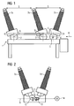
- the FIG. 1 shows a multi-phase switching device 1.
- the multi-phase switching device has three phases A, B, C.
- Each of the three phases A, B, C is associated with a separate encapsulating housing 2, 3, 4.
- the encapsulating housings 2, 3, 4 are each made of an electrically conductive material and surround an interrupter unit of a high-voltage circuit breaker.
- the encapsulating housings 2, 3, 4 have a substantially tubular structure.
- the respective interrupter units of the phases A, B, C are arranged in the interior of the encapsulating 2, 3, 4.
- the main axes project vertically out of the plane of the drawing.
- a main axis 5 of the phase C is in a side view in the FIG.
- FIG. 2 recognizable.
- the line of sight of the representation of FIG. 2 is in the FIG. 1 indicated by an arrow 6.
- Is exemplary in the FIG. 2 an interrupter unit 11 is shown.
- the interrupter unit 11 has a first contact piece 12 and a second contact piece 13.
- the contact pieces 12, 13 are coaxial with the main axis 5.
- the first contact piece 12 is tulip-shaped, the second contact piece 13 is designed bolt-shaped.
- the second contact piece 13 is displaceable via a drive device 14 along the main axis 5.
- the connecting pieces are substantially rotationally symmetrical and are arranged at the ends of the contact pieces 12, 13 facing away from the switching point.
- a first and a second outdoor bushing 7a, b, c, d are respectively arranged on the encapsulation housings 2, 3, 4 on the jacket side.
- the main axes of the phases A, B, C are each arranged in a common plane and aligned parallel to each other. All distances of the major axes of the phases A, B, C are different from each other. Thus, the distance between the major axes of the phases A and C is greater than the distance between the major axes of the phases A and B and greater than the distance between the major axes of the phases B and C. Whereby the distance between the major axes of the phases A and B is greater than the distance between the major axes of phases B and C.
- the main axes are arranged parallel to one another, but lie in different planes, so that a so-called triangular arrangement arises. Also in this case, the distance of all major axes is different from each other. Furthermore, it can also be provided that one or more of the outdoor bushings of the phases A, B, C are in a vertical.
- the axes of the outdoor bushings are pivoted out of a vertical.
- the axes are all deflected by the same amount.
- the outdoor bushings of phases A and B are each deflected with the same sense of direction.
- the outdoor bushings of phase C are deflected by the same amount but with different sense of direction. This results in an arrangement in which the connection points of the outdoor bushings are at the same height, with approximately equal distances S between the connection points of the outer outdoor bushings and the middle outdoor bushing present.
- asymmetric distribution of the main axes is formed between the phases A and B, a receiving space for the arrangement of other modules such as earthing switches or the like. Between phase B and C, such a space is not provided. Due to the asymmetrical arrangement, the entire multi-phase switching device is rotatable about a vertical axis, so that the space provided for retrofitting further modules space can be rotated in the desired position.
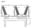
- FIG. 3 By way of example, the equipment of the multi-phase switching device shown in FIG. 1 with an open-circuit grounding switch 8 is shown.
- the Freilufterdungsschalter 8 has at each stage on a pivotable rod which are rotatably mounted near the base of the outdoor bushings 7a, 7b, 7c. There they are also connected to the earth potential.
- the earthing rods in the in the FIG. 3 shown pivoted position upwards be and there in a mating contact at the free end of the respective outdoor bushings 7 a, 7 b, 7 c retract.
- the earthing rods At the two outer phases A, C, the earthing rods are arranged on the outside.
- the ground bar is arranged in the space obtained by the asymmetrical distribution of the breaker unit. Due to the similar but made with different sense direction swiveling and thus achieved the same height of the connection points of the outdoor bushings similar grounding rods at the outdoor earthing switch 8 can be used for all three phases.
- FIG. 4 shows a further embodiment of a phase of a multi-phase switching device, wherein the outdoor bushings 7e, 7f are flanged with the interposition of a respective further housing assembly 9a, 9b to the encapsulating housing 10.
- disconnectors or earthing switches can be arranged in the interior of the other housing assemblies 9a, 9b.
- the circuit breaker for example, via the outdoor bushings 7e, 7f introduced into the interior of the encapsulating housing 10 Worcesteruch can be separated.
- the earthing switch By means of the earthing switch, the corresponding conductor can be acted upon with ground potential.
- the circuit breakers or earthing switches are protected against external environmental influences.
- standing under high voltage potential outdoor bushings further away from the encapsulating housing 10 are flanged to this indirectly. As a result, a threat to operating personnel is avoided because high-voltage parts are further spaced from this.
Landscapes
- Gas-Insulated Switchgears (AREA)
- Driving Mechanisms And Operating Circuits Of Arc-Extinguishing High-Tension Switches (AREA)
Description
Die Erfindung bezieht sich auf ein mehrphasiges Schaltgerät mit zumindest drei gleichartigen Unterbrechereinheiten, die jeweils ein erstes und ein zweites Anschlussstück aufweisen, die jeweils auf einer Hauptachse liegen, wobei die Hauptachsen annähernd parallel zueinander ausgerichtet sind.The invention relates to a multi-phase switching device with at least three similar interrupter units, each having a first and a second connector, each lying on a main axis, wherein the major axes are aligned approximately parallel to each other.
Ein derartiges mehrphasiges Schaltgerät ist beispielsweise aus der Patentschrift
Ein anderes Beispiel ist in
Die Kapselungsgehäuse und damit auch die im Innern befindlichen Unterbrechereinheiten des bekannten mehrphasigen Schaltgerätes sind eng aneinandergerückt. Um eine notwendige Beabstandung luftisolierter elektrischer Leiter an den freien Enden der Freiluftdurchführungen zu gewährleisten, sind diese jeweils fächerartig auseinander gezogen. Durch die kompakte Anordnung der Unterbrechereinheiten zueinander wird eine geringe Aufstellfläche für das elektrische Schaltgerät benötigt. Die Nachrüstung bzw. Erweiterung des bekannten mehrphasigen Schaltgerätes mit weiteren Baugruppen, beispielsweise mit Erdungsschaltern oder Trennschaltern, ist jedoch aufgrund der engen Platzverhältnisse kaum möglich.The encapsulating and thus also located inside the interrupter units of the known multi-phase switching device are close together. In order to ensure a necessary spacing of air-insulated electrical conductors at the free ends of the outdoor bushings, they are each pulled apart like a fan. Due to the compact arrangement of the interrupter units to each other a small footprint for the electrical switching device is needed. However, the retrofitting or expansion of the known multi-phase switching device with other modules, such as earthing switches or circuit breakers, is hardly possible due to the tight space.
Der Erfindung liegt die Aufgabe zugrunde ein mehrphasiges Schaltgerät anzugeben, welches flexibel einsetzbar ist und ausreichende Reserven zum Einbringen von weiteren Baugruppen vorhält.The invention has for its object to provide a multi-phase switching device, which is flexible and reserves sufficient reserves for the introduction of other modules.
Die Aufgabe wird bei einem mehrphasigen Schaltgerät der eingangs genannten Art erfindungsgemäß dadurch gelöst, dass alle Abstände der Hauptachsen voneinander verschiedene Beträge aufweisen.The object is achieved in a multi-phase switching device of the type mentioned in the present invention, that all distances of the major axes have different amounts from each other.
Durch eine Wahl verschiedener Beträge für die Abstände der Hauptachsen der Unterbrechereinheiten zueinander ist ein mehrphasiges Schaltgerät gestaltbar, welches eine asymmetrische Verteilung der Unterbrechereinheiten aufweist. Durch die asymmetrische Verteilung werden an dem Schaltgerät unterschiedliche Bereiche bereitgestellt, die für einen nachträglichen Einbau von weiteren Baugruppen wie beispielsweise Erdungsschaltern, Spannungs- oder Stromwandlern oder ähnlichem zur Verfügung stehen. Die verschiedenen Abstände der Hauptachsen zueinander gestatten es, verschieden große Bereiche bzw. Volumina an dem Schaltgerät vorzusehen, um verschieden große Baugruppen, wie Schaltgeräte, Spannungswandler oder andere Überwachungseinrichtungen, nachzurüsten.By choosing different amounts for the distances of the main axes of the interrupter units to each other, a multi-phase switching device can be designed, which has an asymmetrical distribution of the interrupter units. Due to the asymmetrical distribution different areas are provided on the switching device, which are available for retrofitting of other modules such as earthing switches, voltage or current transformers or the like. The different distances of the main axes to one another make it possible to provide areas of different sizes or volumes on the switching device in order to retrofit components of different sizes, such as switching devices, voltage transformers or other monitoring devices.
Die Unterbrechereinheiten können beispielsweise derart ausgestaltet sein, dass zwei relativ zueinander bewegbare Kontaktstücke axial gegenüberliegend angeordnet sind und eines oder beide Kontaktstücke entlang der Achse verschiebbar sind. An den von der Schaltstelle der Kontaktstücke abgewandten Enden liegen jeweils die Anschlussstücke der Unterbrechereinheit. Bei einer derartigen Ausführung ist die Hauptachse der Unterbrechereinheit und die Achse entlang welcher die Relativbewegung der Kontaktstücke erfolgt annähernd identisch.The breaker units may for example be designed such that two relatively movable contact pieces are arranged axially opposite one another and one or both contact pieces along the axis are displaceable. At the ends facing away from the switching point of the contact pieces are in each case the connecting pieces of the interrupter unit. In such an embodiment, the main axis of the interrupter unit and the axis along which the relative movement of the contact pieces is approximately identical.
Die Anschlussstücke sind dann vorteilhaft im Wesentlichen rotationssymmetrisch ausgestaltet und koaxial zu der Achse angeordnet.The connecting pieces are then advantageously designed substantially rotationally symmetrical and arranged coaxially with the axis.
Vorteilhafterweise kann vorgesehen sein, dass die Hauptachsen in einer gemeinsamen Ebene angeordnet sind.Advantageously, it can be provided that the main axes are arranged in a common plane.
Bei einer Anordnung der Hauptachsen in einer gemeinsamen Ebene kann das Schaltgerät beispielsweise in einer Dead-Tank-Bauweise ausgeführt sein. Durch die Anordnungen in einer Ebene in Verbindung mit der Wahl der Abstände der Hauptachsen zueinander stehen zwischen den Unterbrechereinheiten der einzelnen Phasen Bereiche verschiedener Größe zum Einbau verschieden großer Elemente zur Verfügung.With an arrangement of the main axes in a common plane, the switching device can be designed, for example, in a dead tank design. Due to the arrangements in a plane in connection with the choice of the distances of the main axes to each other are between the breaker units of the individual phases areas of different sizes for the installation of different sized elements available.
Dabei kann weiterhin vorteilhaft vorgesehen sein, dass jede der Unterbrechereinheiten von einem separaten Kapselungsgehäuse umgeben ist.In this case, it can furthermore be advantageously provided that each of the interrupter units is surrounded by a separate encapsulating housing.
Die Ummantelung der Unterbrechereinheiten mit separaten Kapselungsgehäusen ermöglicht weiterhin die Abstände der Hauptachsen voneinander je nach Aufstellungsort variabel festzulegen. Jedes der Kapselungsgehäuse mit den jeweiligen Unterbrechereinheiten wirkt hinsichtlich Lichtbogenlöschung, Isolationsfestigkeit usw. unabhängig von den anderen.The sheathing of the interrupter units with separate encapsulation housings also makes it possible to variably set the distances of the main axes from one another depending on the site of installation. Each of the encapsulating housings with the respective breaker units acts independently of the others in terms of arc extinction, insulation resistance and so on.
Eine weitere vorteilhafte Ausgestaltung kann vorsehen, dass zum elektrischen Anschluss der Unterbrechereinheiten jeweils zumindest eine Freiluftdurchführung mit im Wesentlichen radialer Ausrichtung zur Hauptachse des jeweiligen Kapselungsgehäuses angeordnet ist.A further advantageous embodiment can provide that at least one outdoor bushing is arranged with an essentially radial orientation to the main axis of the respective encapsulating housing for the electrical connection of the interrupter units.
Mittels Freiluftdurchführungen können elektrische Leitungen sicher in das Innere des Kapselungsgehäuses eingeführt werden. Die radiale Ausrichtung gestattet eine sichere Beabstandung von spannungsführenden Teilen zu dem Gehäuse. So kann das Kapselungsgehäuse beispielsweise aus einem elektrisch leitenden Material bestehen und selbst Erdpotential führen. Dadurch entstehen robuste wetterbeständige Anordnungen, die beispielsweise auch unter erschwerten klimatischen Verhältnissen einsetzbar sind.By means of outdoor bushings electrical lines can be safely inserted into the interior of the encapsulating. The radial alignment allows safe spacing of live parts to the housing. For example, the encapsulating housing can consist of an electrically conductive material and can itself carry ground potential. This results in robust weather-resistant arrangements that can be used for example under difficult climatic conditions.
Eine weitere vorteilhafte Ausgestaltung kann vorsehen, dass zwei Freiluftdurchführungen jeweils um die Hauptachsen mit entgegengesetztem Richtungssinn aus einer Senkrechten verschwenkt sind und eine Freiluftdurchführung in der Senkrechten angeordnet ist.A further advantageous embodiment can provide that two outdoor bushings are each pivoted about the main axes with opposite sense of direction from a vertical and an outdoor bushing is arranged in the vertical.
Eine derartige Ausgestaltung kann beispielsweise zur Ausgestaltung von fächerförmig zueinander angeordneten Freiluftdurchführungen von drei Phasen des Schaltgerätes führen. Dadurch kann in einfacher Weise eine ausreichende Schlagweite an den verschiedene elektrische Potentiale führenden freien Enden der Freiluftdurchführungen erzeugt werden.Such a configuration may, for example, lead to the design of fan-shaped outdoor bushings of three phases of the switching device arranged in a fan-shaped manner. As a result, a sufficient impact distance at the different electrical potentials leading free ends of the outdoor bushings can be generated in a simple manner.
Weiterhin kann vorteilhaft vorgesehen sein, dass alle Freiluftdurchführungen um bis zu maximal 45° aus einer Senkrechten jeweils um die Hauptachsen verschwenkt sind, wobei eine Freiluftdurchführung mit von den anderen Freiluftdurchführungen abweichendem Richtungssinn ausgeschwenkt ist.Furthermore, it can be advantageously provided that all outdoor bushings are pivoted by up to a maximum of 45 ° from a vertical respectively about the main axes, wherein an outdoor bushing is swung out with deviating from the other outdoor bushings sense of direction.
In Verbindung mit den unterschiedlichen Abständen der Hauptachsen der Unterbrechereinheiten und einer Verschwenkung aller Freiluftdurchführungen, wobei eine der Freiluftdurchführungen mit einem unterschiedlichen Richtungssinn ausgeschwenkt ist, ist die Einhaltung ausreichender Schlagweiten zwischen den Freiluftdurchführungen gewährleistet. Zusätzlich kann bei einer Anordnung der Unterbrechereinheiten in einer Ebene erreicht werden, dass die Höhe der Anschlussstellen an den freien Enden der Freiluftdurchführungen jeweils bei allen Phasen gleich ist. Dadurch ergeben sich Vorteile bei einer beengten Aufstellung des elektrischen Schaltgerätes beispielsweise unter einer Hochspannungsleitung. Gegenüber symmetrisch aufgefächerten Freiluftdurchführungen, bei denen der Anschlusspunkt der mittig angeordneten Durchführung höher liegt, als die Anschlusspunkte von seitlich abgeschwenkten Freiluftdurchführungen, ist eine Verwendung eines erfindungsgemäßen Schaltgerätes auch auf überbauten Flächen geringer Höhe möglich.In conjunction with the different distances of the main axes of the breaker units and a pivoting of all outdoor bushings, wherein one of the outdoor bushings swung with a different sense of direction is, the observance of sufficient impact distance between the outdoor bushings is guaranteed. In addition, with an arrangement of the interrupter units in a plane can be achieved that the height of the connection points at the free ends of the outdoor bushings is the same for all phases. This results in advantages in a cramped installation of the electrical switching device, for example, under a high voltage line. Compared with symmetrically fanned outdoor bushings in which the connection point of the centrally arranged passage is higher than the connection points of laterally pivoted outdoor bushings, a use of a switching device according to the invention is also possible on built-up areas of low height.
Weiterhin kann vorteilhaft vorgesehen sein, dass das Schaltgerät ein einphasig gekapseltes Schaltgerät in Dead-Tank-Bauweise ist und das Schaltgerät ein Hochspannungs-Leistungsschalter ist.Furthermore, it can be advantageously provided that the switching device is a single-phase encapsulated switching device in dead-tank design and the switching device is a high-voltage circuit breaker.
Schaltgeräte in Dead-Tank-Bauweise sind beispielsweise aus dem Stand der Technik bekannt. Eine erfindungsgemäße Ausgestaltung eines Hochspannungsleistungsschalters in Dead-Tank-Bauweise ist zu bereits bestehenden Anordnungen kompatibel, das heißt, bei einem Ersatz von verschlissenen Hochspannungs-Leistungsschaltern kann so in einfacher Weise ein erfindungsgemäßer Hochspannungs-Leistungsschalter Verwendung finden.Switchgear in dead-tank design are known for example from the prior art. An inventive design of a high-voltage circuit breaker in dead-tank design is compatible with existing arrangements, that is, in a replacement of worn high-voltage circuit breakers can thus easily find an inventive high-voltage circuit breaker use.
Es kann vorteilhafterweise weiterhin vorgesehen sein, dass zumindest eine Freiluftdurchführung unmittelbar an einem am Kapselungsgehäuse angeordneten Flansch angeflanscht ist.It can be advantageously further provided that at least one outdoor bushing is flanged directly to a flange arranged on the encapsulating housing.
Durch ein unmittelbares Anflanschen einer Freiluftdurchführung an das Kapselungsgehäuse entsteht eine mechanisch stabile Einheit. Schwingungen der Freiluftdurchführungen aufgrund von Schalthandlungen oder Windlasten können auf ein zulässiges Maß begrenzt werden.By directly flanging an outdoor bushing to the encapsulating a mechanically stable unit is formed. Vibrations of the outdoor bushings due to switching operations or wind loads can be limited to a permissible level.
Eine weitere vorteilhafte Ausgestaltung kann vorsehen, dass zumindest eine Freiluftdurchführung mittelbar unter Zwischenbau einer weiteren Gehäusebaugruppe an ein Kapselungsgehäuse angeflanscht ist.A further advantageous embodiment can provide that at least one outdoor bushing is flanged indirectly to an encapsulating housing with the interposition of a further housing assembly.
Der Zwischenbau einer weiteren Gehäusebaugruppe ermöglicht es, weitere Bauteile in kompakter Form an das mehrphasige Schaltgerät anzubauen. Dazu kann beispielsweise der Innenraum der Gehäusebaugruppe genutzt werden.The intermediate construction of another housing assembly makes it possible to attach additional components in a compact form to the multiphase switching device. For this purpose, for example, the interior of the housing assembly can be used.
Dabei kann vorteilhaft vorgesehen sein, dass in der weiteren Gehäusebaugruppe ein Trennschalter und/oder ein Erdungsschalter angeordnet ist.It can be advantageously provided that in the further housing assembly, a circuit breaker and / or a grounding switch is arranged.
Durch die Anordnung von Trennschaltern bzw. Erdungsschaltern innerhalb einer weiteren Gehäusebaugruppe sind diese vor äußeren Umwelteinflüssen geschützt. Gleichzeitig wird die Umwelt vor Gefährdungen, die von den im Innern der Gehäusebaugruppe angeordneten Schaltgeräten ausgehen, bewahrt.The arrangement of disconnectors or earthing switches within a further housing assembly protects them from external environmental influences. At the same time, the environment is protected from hazards emanating from the switching devices arranged in the interior of the housing assembly.
Zusätzlich wird mit einer Ausrüstung des mehrphasigen Schaltgerätes mit einer weiteren Gehäusebaugruppe die Anzahl von möglichen Schaltungsvarianten erhöht. Damit ist das mehrphasige elektrische Schaltgerät vielfältig einsetzbar. So kann beispielsweise vorgesehen sein, dass über den Erdungsschalter und den Trennschalter einzelne Freileitungsabschnitte freigeschaltet werden und diese anschließend geerdet werden.In addition, with the equipment of the multiphase switching device with a further housing assembly, the number of possible circuit variants is increased. Thus, the multi-phase electrical switching device is versatile. For example, it may be provided that individual overhead line sections are disconnected via the earthing switch and the disconnector, and that these are then earthed.
Im Folgenden wird ein Ausführungsbeispiel der Erfindung schematisch in einer Zeichnung gezeigt und nachfolgend näher beschrieben. Dabei zeigt die
- Figur 1
- eine stirnseitige Ansicht eines mehrphasigen Schaltgerätes, die
Figur 2- eine seitliche Ansicht des in der
Figur 1 dargestellten mehrphasigen Schaltgerätes, die Figur 3- eine stirnseitige Ansicht des aus der
Figur 1 bekannten Schaltgerätes mit einem Freilufterdungsschalter sowie die - Figur 4
- eine seitliche Ansicht eines elektrischen Schaltgerätes mit Freiluftdurchführungen und zwischengebauten weiteren Gehäusebaugruppen.
- FIG. 1
- an end view of a multi-phase switching device, the
- FIG. 2
- a side view of the in the
FIG. 1 shown multi-phase switching device, the - FIG. 3
- an end view of the from the
FIG. 1 known switching device with a Freilufterdungsschalter and the - FIG. 4
- a side view of an electrical switching device with outdoor bushings and interposed other housing assemblies.
Die
Zur Zuführung der elektrischen Leitungen zu den im Innern der Kapselungsgehäuse 2, 3, 4 befindlichen Unterbrechereinheiten sind an den Kapselungsgehäusen 2, 3, 4 mantelseitig jeweils eine erste und eine zweite Freiluftdurchführung 7a, b, c, d angeordnet. Die Hauptachsen der Phasen A, B, C sind jeweils in einer gemeinsamen Ebene angeordnet und zueinander parallel ausgerichtet. Alle Abstände der Hauptachsen der Phasen A, B, C sind voneinander verschieden. So ist der Abstand zwischen den Hauptachsen der Phasen A und C größer, als der Abstand der zwischen den Hauptachsen der Phasen A und B sowie größer als der Abstand zwischen den Hauptachsen der Phasen B und C. Wobei der Abstand zwischen den Hauptachsen der Phasen A und B wiederum größer ist, als der Abstand zwischen den Hauptachsen der Phasen B und C.For supplying the electrical lines to the interrupter units located in the interior of the encapsulating
Neben der in der
Um eine ausreichende Schlagweite S an den freien Enden der Freiluftdurchführungen zu gewährleisten, sind die Achsen der Freiluftdurchführungen aus einer Senkrechten heraus geschwenkt. Dabei sind die Achsen alle um denselben Betrag ausgelenkt. Die Freiluftdurchführungen der Phasen A und B sind jeweils mit demselben Richtungssinn ausgelenkt. Die Freiluftdurchführungen der Phase C sind zwar um denselben Betrag jedoch mit unterschiedlichem Richtungssinn ausgelenkt. Dadurch entsteht eine Anordnung, bei welcher die Anschlusspunkte der Freiluftdurchführungen in ein und derselben Höhe liegen, wobei etwa gleiche Abstände S zwischen den Anschlusspunkten der äußeren Freiluftdurchführungen und der mittleren Freiluftdurchführung vorliegen.In order to ensure a sufficient impact distance S at the free ends of the outdoor bushings, the axes of the outdoor bushings are pivoted out of a vertical. The axes are all deflected by the same amount. The outdoor bushings of phases A and B are each deflected with the same sense of direction. Although the outdoor bushings of phase C are deflected by the same amount but with different sense of direction. This results in an arrangement in which the connection points of the outdoor bushings are at the same height, with approximately equal distances S between the connection points of the outer outdoor bushings and the middle outdoor bushing present.
Bei der in der
In der
Die
Claims (11)
- Polyphase switching device (1) comprising at least three similar interrupter units (11), which each have a first and a second connection piece, which each lie on a main axis, the main axes being aligned approximately parallel to one another, characterized in that all of the distances between the main axes have different absolute values.
- Polyphase switching device (1) according to Claim 1, characterized in that the main axes are arranged in a common plane.
- Polyphase switching device (1) according to either of Claims 1 and 2, characterized in that each of the interrupter units (11) is surrounded by a separate encapsulating housing (2, 3, 4).
- Polyphase switching device (1) according to Claim 3, characterized in that, in order to electrically connect the interrupter units (11), in each case at least one outdoor bushing (7a, b, c, d) is arranged with a substantially radial alignment with respect to the main axis of the respective encapsulating housing (2, 3, 4).
- Polyphase switching device (1) according to Claim 4, characterized in that two outdoor bushings (7a, b, c, d) are each pivoted about the main axes with opposite sense of direction out of a perpendicular, and an outdoor bushing is arranged in the perpendicular.
- Polyphase switching device (1) according to Claim 5, characterized in that all of the outdoor bushings (7a, b, c, d) are pivoted through up to a maximum of 45° out of a perpendicular in each case about the main axes, with one outdoor bushing being pivoted out with a sense of direction which is different from that of the other outdoor bushings (7a, b, c, d).
- Polyphase switching device (1) according to one of Claims 1 to 6, characterized in that the switching device is a single-phase-encapsulated switching device with a dead tank design and the switching device is a high-voltage circuit breaker.
- Polyphase switching device (1) according to one of Claims 4 to 7, characterized in that at least one outdoor bushing (7a, b, c, d) is flange-connected directly on a flange arranged on the encapsulating housing (2, 3, 4).
- Polyphase switching device (1) according to one of Claims 4 to 7, characterized in that at least one outdoor bushing (7a, b, c, d) is flange-connected to an encapsulating housing (10) indirectly, with a further housing assembly (9a, 9b) interposed.
- Polyphase switching device (1) according to Claim 9, characterized in that a switch disconnector is arranged in the further housing assembly (9a, 9b).
- Polyphase switching device (1) according to Claim 9 or 10, characterized in that a grounding switch is arranged in the further housing assembly (9a, 9b).
Applications Claiming Priority (2)
| Application Number | Priority Date | Filing Date | Title |
|---|---|---|---|
| DE102004061277A DE102004061277A1 (en) | 2004-12-13 | 2004-12-13 | Multi-phase switching device with at least three similar breaker units |
| PCT/EP2005/056303 WO2006063928A1 (en) | 2004-12-13 | 2005-11-29 | Polyphase switching device comprising at least three similar interrupter units |
Publications (2)
| Publication Number | Publication Date |
|---|---|
| EP1825488A1 EP1825488A1 (en) | 2007-08-29 |
| EP1825488B1 true EP1825488B1 (en) | 2008-09-17 |
Family
ID=35788697
Family Applications (1)
| Application Number | Title | Priority Date | Filing Date |
|---|---|---|---|
| EP05816245A Not-in-force EP1825488B1 (en) | 2004-12-13 | 2005-11-29 | Polyphase switching device comprising at least three similar interrupter units |
Country Status (9)
| Country | Link |
|---|---|
| US (1) | US20080105654A1 (en) |
| EP (1) | EP1825488B1 (en) |
| CN (1) | CN100594569C (en) |
| CA (1) | CA2590504A1 (en) |
| DE (2) | DE102004061277A1 (en) |
| ES (1) | ES2312039T3 (en) |
| MX (1) | MX2007007089A (en) |
| RU (1) | RU2389103C2 (en) |
| WO (1) | WO2006063928A1 (en) |
Families Citing this family (4)
| Publication number | Priority date | Publication date | Assignee | Title |
|---|---|---|---|---|
| WO2007051319A1 (en) * | 2005-11-02 | 2007-05-10 | Abb Technology Ag | High-voltage circuit breaker and breaker arrangement |
| RU2580937C1 (en) * | 2014-12-22 | 2016-04-10 | Общество с ограниченной ответственностью "Эльмаш (УЭТМ)" | Combined gas-filled high-voltage apparatus |
| US10818452B1 (en) | 2018-08-30 | 2020-10-27 | Robert Neal Hendrix | Power outage isolation device |
| EP3671990B1 (en) * | 2018-12-19 | 2021-11-24 | ABB Schweiz AG | Three phase switchgear or control gear |
Family Cites Families (7)
| Publication number | Priority date | Publication date | Assignee | Title |
|---|---|---|---|---|
| JPS63168926A (en) * | 1986-12-30 | 1988-07-12 | 株式会社日立製作所 | Tank type gas breaker |
| EP0405253A1 (en) * | 1989-06-30 | 1991-01-02 | Sprecher Energie AG | Three phase gas insulated switchgear |
| DE19511168A1 (en) * | 1995-03-28 | 1996-10-02 | Abb Management Ag | Switching device |
| IT1313321B1 (en) * | 1999-10-01 | 2002-07-17 | Abb Ricerca Spa | INTERRUPT AND SECTIONING EQUIPMENT INSULATED IN GAS. |
| US6630638B1 (en) * | 2000-05-26 | 2003-10-07 | Abb Inc. | Dead tank drawout breakers |
| JP2002051415A (en) * | 2000-08-02 | 2002-02-15 | Toshiba Corp | Composite gas-insulated switchgear |
| AU763276B2 (en) * | 2001-02-07 | 2003-07-17 | Hitachi Limited | Gas insulated switchgear |
-
2004
- 2004-12-13 DE DE102004061277A patent/DE102004061277A1/en not_active Withdrawn
-
2005
- 2005-11-29 CN CN200580041969A patent/CN100594569C/en not_active Expired - Fee Related
- 2005-11-29 CA CA002590504A patent/CA2590504A1/en not_active Abandoned
- 2005-11-29 MX MX2007007089A patent/MX2007007089A/en active IP Right Grant
- 2005-11-29 US US11/793,182 patent/US20080105654A1/en not_active Abandoned
- 2005-11-29 EP EP05816245A patent/EP1825488B1/en not_active Not-in-force
- 2005-11-29 WO PCT/EP2005/056303 patent/WO2006063928A1/en active IP Right Grant
- 2005-11-29 DE DE502005005434T patent/DE502005005434D1/en active Active
- 2005-11-29 ES ES05816245T patent/ES2312039T3/en active Active
- 2005-11-29 RU RU2007126650/09A patent/RU2389103C2/en not_active IP Right Cessation
Also Published As
| Publication number | Publication date |
|---|---|
| WO2006063928A1 (en) | 2006-06-22 |
| DE102004061277A1 (en) | 2006-06-22 |
| MX2007007089A (en) | 2007-08-08 |
| CN101073132A (en) | 2007-11-14 |
| CN100594569C (en) | 2010-03-17 |
| RU2007126650A (en) | 2009-01-20 |
| ES2312039T3 (en) | 2009-02-16 |
| DE502005005434D1 (en) | 2008-10-30 |
| EP1825488A1 (en) | 2007-08-29 |
| RU2389103C2 (en) | 2010-05-10 |
| CA2590504A1 (en) | 2006-06-22 |
| US20080105654A1 (en) | 2008-05-08 |
Similar Documents
| Publication | Publication Date | Title |
|---|---|---|
| DE3715053C2 (en) | ||
| DE60126185T2 (en) | Gas-insulated switchgear | |
| EP1756924A1 (en) | Power switch comprising a interrupter unit housed in protective housing | |
| EP0678955B1 (en) | Metal-clad gas-insulated switch installation | |
| EP2254135B1 (en) | Metal-enclosed, multi-phase gas-insulated busbar disconnecting and earthing switch | |
| EP0678954A1 (en) | Metal-clad gas-insulated switch installation | |
| EP1829075B2 (en) | High voltage switchgear | |
| EP1825488B1 (en) | Polyphase switching device comprising at least three similar interrupter units | |
| DE102006040037A1 (en) | Connection module with an encapsulating housing | |
| DE202006008709U1 (en) | Connection switch panel e.g. circuit breaker panel, for medium voltage switch gear, has supply devices connected with bus branch over three position switches having contact, separation and grounding positions | |
| DE3318344C2 (en) | High voltage switchgear | |
| DE19805705A1 (en) | Gas-insulated metal-enclosed switchgear | |
| DE3521945A1 (en) | DISCONNECTOR FOR A METAL-ENCLOSED, PRESSURE-GAS INSULATED HIGH-VOLTAGE SWITCHGEAR | |
| EP1629581B1 (en) | Disconnecting switch assembly | |
| EP1629580B1 (en) | Switch assembly | |
| EP0878816A2 (en) | Metal-clad gas insulated power switch | |
| EP0875971A2 (en) | High voltage switchgear | |
| EP2891215A1 (en) | Switchgear assembly switchpanel | |
| EP3488457A1 (en) | Apparatus and method for switching medium and high voltages | |
| EP1629578A2 (en) | Gas-insulated bus bar component comprising outdoor bushings | |
| DE19641391C1 (en) | Hybrid type high-voltage switchgear | |
| DE1540176A1 (en) | Encapsulated switching device for medium or high voltage | |
| DE102006031219A1 (en) | Circuit breaker with a housing | |
| EP1513236A2 (en) | Gas insulated cable connector | |
| DE102020210912A1 (en) | A gas-insulated medium or high-voltage switchgear with a blade contact carrier |
Legal Events
| Date | Code | Title | Description |
|---|---|---|---|
| PUAI | Public reference made under article 153(3) epc to a published international application that has entered the european phase |
Free format text: ORIGINAL CODE: 0009012 |
|
| 17P | Request for examination filed |
Effective date: 20070604 |
|
| AK | Designated contracting states |
Kind code of ref document: A1 Designated state(s): CH DE ES FR IT LI |
|
| DAX | Request for extension of the european patent (deleted) | ||
| RBV | Designated contracting states (corrected) |
Designated state(s): CH DE ES FR IT LI |
|
| GRAP | Despatch of communication of intention to grant a patent |
Free format text: ORIGINAL CODE: EPIDOSNIGR1 |
|
| GRAS | Grant fee paid |
Free format text: ORIGINAL CODE: EPIDOSNIGR3 |
|
| GRAA | (expected) grant |
Free format text: ORIGINAL CODE: 0009210 |
|
| AK | Designated contracting states |
Kind code of ref document: B1 Designated state(s): CH DE ES FR IT LI |
|
| REG | Reference to a national code |
Ref country code: CH Ref legal event code: EP |
|
| REF | Corresponds to: |
Ref document number: 502005005434 Country of ref document: DE Date of ref document: 20081030 Kind code of ref document: P |
|
| REG | Reference to a national code |
Ref country code: CH Ref legal event code: NV Representative=s name: SIEMENS SCHWEIZ AG |
|
| REG | Reference to a national code |
Ref country code: ES Ref legal event code: FG2A Ref document number: 2312039 Country of ref document: ES Kind code of ref document: T3 |
|
| REG | Reference to a national code |
Ref country code: CH Ref legal event code: PCAR Free format text: SIEMENS SCHWEIZ AG;INTELLECTUAL PROPERTY FREILAGERSTRASSE 40;8047 ZUERICH (CH) |
|
| PLBE | No opposition filed within time limit |
Free format text: ORIGINAL CODE: 0009261 |
|
| STAA | Information on the status of an ep patent application or granted ep patent |
Free format text: STATUS: NO OPPOSITION FILED WITHIN TIME LIMIT |
|
| 26N | No opposition filed |
Effective date: 20090618 |
|
| PGFP | Annual fee paid to national office [announced via postgrant information from national office to epo] |
Ref country code: IT Payment date: 20101125 Year of fee payment: 6 |
|
| PGFP | Annual fee paid to national office [announced via postgrant information from national office to epo] |
Ref country code: ES Payment date: 20111213 Year of fee payment: 7 Ref country code: FR Payment date: 20111201 Year of fee payment: 7 |
|
| PGFP | Annual fee paid to national office [announced via postgrant information from national office to epo] |
Ref country code: CH Payment date: 20120206 Year of fee payment: 7 |
|
| PGFP | Annual fee paid to national office [announced via postgrant information from national office to epo] |
Ref country code: DE Payment date: 20120120 Year of fee payment: 7 |
|
| REG | Reference to a national code |
Ref country code: CH Ref legal event code: PL |
|
| PG25 | Lapsed in a contracting state [announced via postgrant information from national office to epo] |
Ref country code: LI Free format text: LAPSE BECAUSE OF NON-PAYMENT OF DUE FEES Effective date: 20121130 Ref country code: CH Free format text: LAPSE BECAUSE OF NON-PAYMENT OF DUE FEES Effective date: 20121130 |
|
| REG | Reference to a national code |
Ref country code: FR Ref legal event code: ST Effective date: 20130731 |
|
| PG25 | Lapsed in a contracting state [announced via postgrant information from national office to epo] |
Ref country code: IT Free format text: LAPSE BECAUSE OF NON-PAYMENT OF DUE FEES Effective date: 20121129 |
|
| REG | Reference to a national code |
Ref country code: DE Ref legal event code: R119 Ref document number: 502005005434 Country of ref document: DE Effective date: 20130601 |
|
| PG25 | Lapsed in a contracting state [announced via postgrant information from national office to epo] |
Ref country code: DE Free format text: LAPSE BECAUSE OF NON-PAYMENT OF DUE FEES Effective date: 20130601 |
|
| PG25 | Lapsed in a contracting state [announced via postgrant information from national office to epo] |
Ref country code: FR Free format text: LAPSE BECAUSE OF NON-PAYMENT OF DUE FEES Effective date: 20121130 |
|
| REG | Reference to a national code |
Ref country code: ES Ref legal event code: FD2A Effective date: 20140527 |
|
| PG25 | Lapsed in a contracting state [announced via postgrant information from national office to epo] |
Ref country code: ES Free format text: LAPSE BECAUSE OF NON-PAYMENT OF DUE FEES Effective date: 20121130 |