EP1824395B1 - Devices and systems for material fixation - Google Patents
Devices and systems for material fixation Download PDFInfo
- Publication number
- EP1824395B1 EP1824395B1 EP05851848.1A EP05851848A EP1824395B1 EP 1824395 B1 EP1824395 B1 EP 1824395B1 EP 05851848 A EP05851848 A EP 05851848A EP 1824395 B1 EP1824395 B1 EP 1824395B1
- Authority
- EP
- European Patent Office
- Prior art keywords
- anchor
- tendon
- bone
- direct
- view
- Prior art date
- Legal status (The legal status is an assumption and is not a legal conclusion. Google has not performed a legal analysis and makes no representation as to the accuracy of the status listed.)
- Not-in-force
Links
Images


Classifications
-
- A—HUMAN NECESSITIES
- A61—MEDICAL OR VETERINARY SCIENCE; HYGIENE
- A61B—DIAGNOSIS; SURGERY; IDENTIFICATION
- A61B17/00—Surgical instruments, devices or methods, e.g. tourniquets
- A61B17/04—Surgical instruments, devices or methods, e.g. tourniquets for suturing wounds; Holders or packages for needles or suture materials
- A61B17/0401—Suture anchors, buttons or pledgets, i.e. means for attaching sutures to bone, cartilage or soft tissue; Instruments for applying or removing suture anchors
-
- A—HUMAN NECESSITIES
- A61—MEDICAL OR VETERINARY SCIENCE; HYGIENE
- A61F—FILTERS IMPLANTABLE INTO BLOOD VESSELS; PROSTHESES; DEVICES PROVIDING PATENCY TO, OR PREVENTING COLLAPSING OF, TUBULAR STRUCTURES OF THE BODY, e.g. STENTS; ORTHOPAEDIC, NURSING OR CONTRACEPTIVE DEVICES; FOMENTATION; TREATMENT OR PROTECTION OF EYES OR EARS; BANDAGES, DRESSINGS OR ABSORBENT PADS; FIRST-AID KITS
- A61F2/00—Filters implantable into blood vessels; Prostheses, i.e. artificial substitutes or replacements for parts of the body; Appliances for connecting them with the body; Devices providing patency to, or preventing collapsing of, tubular structures of the body, e.g. stents
- A61F2/02—Prostheses implantable into the body
- A61F2/08—Muscles; Tendons; Ligaments
- A61F2/0811—Fixation devices for tendons or ligaments
-
- A—HUMAN NECESSITIES
- A61—MEDICAL OR VETERINARY SCIENCE; HYGIENE
- A61B—DIAGNOSIS; SURGERY; IDENTIFICATION
- A61B17/00—Surgical instruments, devices or methods, e.g. tourniquets
- A61B2017/00831—Material properties
- A61B2017/00862—Material properties elastic or resilient
-
- A—HUMAN NECESSITIES
- A61—MEDICAL OR VETERINARY SCIENCE; HYGIENE
- A61B—DIAGNOSIS; SURGERY; IDENTIFICATION
- A61B17/00—Surgical instruments, devices or methods, e.g. tourniquets
- A61B17/04—Surgical instruments, devices or methods, e.g. tourniquets for suturing wounds; Holders or packages for needles or suture materials
- A61B17/0401—Suture anchors, buttons or pledgets, i.e. means for attaching sutures to bone, cartilage or soft tissue; Instruments for applying or removing suture anchors
- A61B2017/0409—Instruments for applying suture anchors
-
- A—HUMAN NECESSITIES
- A61—MEDICAL OR VETERINARY SCIENCE; HYGIENE
- A61B—DIAGNOSIS; SURGERY; IDENTIFICATION
- A61B17/00—Surgical instruments, devices or methods, e.g. tourniquets
- A61B17/04—Surgical instruments, devices or methods, e.g. tourniquets for suturing wounds; Holders or packages for needles or suture materials
- A61B17/0401—Suture anchors, buttons or pledgets, i.e. means for attaching sutures to bone, cartilage or soft tissue; Instruments for applying or removing suture anchors
- A61B2017/0412—Suture anchors, buttons or pledgets, i.e. means for attaching sutures to bone, cartilage or soft tissue; Instruments for applying or removing suture anchors having anchoring barbs or pins extending outwardly from suture anchor body
-
- A—HUMAN NECESSITIES
- A61—MEDICAL OR VETERINARY SCIENCE; HYGIENE
- A61B—DIAGNOSIS; SURGERY; IDENTIFICATION
- A61B17/00—Surgical instruments, devices or methods, e.g. tourniquets
- A61B17/04—Surgical instruments, devices or methods, e.g. tourniquets for suturing wounds; Holders or packages for needles or suture materials
- A61B17/0401—Suture anchors, buttons or pledgets, i.e. means for attaching sutures to bone, cartilage or soft tissue; Instruments for applying or removing suture anchors
- A61B2017/0414—Suture anchors, buttons or pledgets, i.e. means for attaching sutures to bone, cartilage or soft tissue; Instruments for applying or removing suture anchors having a suture-receiving opening, e.g. lateral opening
-
- A—HUMAN NECESSITIES
- A61—MEDICAL OR VETERINARY SCIENCE; HYGIENE
- A61B—DIAGNOSIS; SURGERY; IDENTIFICATION
- A61B17/00—Surgical instruments, devices or methods, e.g. tourniquets
- A61B17/04—Surgical instruments, devices or methods, e.g. tourniquets for suturing wounds; Holders or packages for needles or suture materials
- A61B17/0401—Suture anchors, buttons or pledgets, i.e. means for attaching sutures to bone, cartilage or soft tissue; Instruments for applying or removing suture anchors
- A61B2017/0427—Suture anchors, buttons or pledgets, i.e. means for attaching sutures to bone, cartilage or soft tissue; Instruments for applying or removing suture anchors having anchoring barbs or pins extending outwardly from the anchor body
- A61B2017/0435—Suture anchors, buttons or pledgets, i.e. means for attaching sutures to bone, cartilage or soft tissue; Instruments for applying or removing suture anchors having anchoring barbs or pins extending outwardly from the anchor body the barbs being separate elements mechanically linked to the anchor, e.g. by pivots
-
- A—HUMAN NECESSITIES
- A61—MEDICAL OR VETERINARY SCIENCE; HYGIENE
- A61B—DIAGNOSIS; SURGERY; IDENTIFICATION
- A61B17/00—Surgical instruments, devices or methods, e.g. tourniquets
- A61B17/04—Surgical instruments, devices or methods, e.g. tourniquets for suturing wounds; Holders or packages for needles or suture materials
- A61B17/0401—Suture anchors, buttons or pledgets, i.e. means for attaching sutures to bone, cartilage or soft tissue; Instruments for applying or removing suture anchors
- A61B2017/0427—Suture anchors, buttons or pledgets, i.e. means for attaching sutures to bone, cartilage or soft tissue; Instruments for applying or removing suture anchors having anchoring barbs or pins extending outwardly from the anchor body
- A61B2017/0437—Suture anchors, buttons or pledgets, i.e. means for attaching sutures to bone, cartilage or soft tissue; Instruments for applying or removing suture anchors having anchoring barbs or pins extending outwardly from the anchor body the barbs being resilient or spring-like
-
- A—HUMAN NECESSITIES
- A61—MEDICAL OR VETERINARY SCIENCE; HYGIENE
- A61F—FILTERS IMPLANTABLE INTO BLOOD VESSELS; PROSTHESES; DEVICES PROVIDING PATENCY TO, OR PREVENTING COLLAPSING OF, TUBULAR STRUCTURES OF THE BODY, e.g. STENTS; ORTHOPAEDIC, NURSING OR CONTRACEPTIVE DEVICES; FOMENTATION; TREATMENT OR PROTECTION OF EYES OR EARS; BANDAGES, DRESSINGS OR ABSORBENT PADS; FIRST-AID KITS
- A61F2/00—Filters implantable into blood vessels; Prostheses, i.e. artificial substitutes or replacements for parts of the body; Appliances for connecting them with the body; Devices providing patency to, or preventing collapsing of, tubular structures of the body, e.g. stents
- A61F2/02—Prostheses implantable into the body
- A61F2/08—Muscles; Tendons; Ligaments
- A61F2/0805—Implements for inserting tendons or ligaments
-
- A—HUMAN NECESSITIES
- A61—MEDICAL OR VETERINARY SCIENCE; HYGIENE
- A61F—FILTERS IMPLANTABLE INTO BLOOD VESSELS; PROSTHESES; DEVICES PROVIDING PATENCY TO, OR PREVENTING COLLAPSING OF, TUBULAR STRUCTURES OF THE BODY, e.g. STENTS; ORTHOPAEDIC, NURSING OR CONTRACEPTIVE DEVICES; FOMENTATION; TREATMENT OR PROTECTION OF EYES OR EARS; BANDAGES, DRESSINGS OR ABSORBENT PADS; FIRST-AID KITS
- A61F2/00—Filters implantable into blood vessels; Prostheses, i.e. artificial substitutes or replacements for parts of the body; Appliances for connecting them with the body; Devices providing patency to, or preventing collapsing of, tubular structures of the body, e.g. stents
- A61F2/02—Prostheses implantable into the body
- A61F2/08—Muscles; Tendons; Ligaments
- A61F2/0811—Fixation devices for tendons or ligaments
- A61F2002/0847—Mode of fixation of anchor to tendon or ligament
- A61F2002/0852—Fixation of a loop or U-turn, e.g. eyelets, anchor having multiple holes
-
- A—HUMAN NECESSITIES
- A61—MEDICAL OR VETERINARY SCIENCE; HYGIENE
- A61F—FILTERS IMPLANTABLE INTO BLOOD VESSELS; PROSTHESES; DEVICES PROVIDING PATENCY TO, OR PREVENTING COLLAPSING OF, TUBULAR STRUCTURES OF THE BODY, e.g. STENTS; ORTHOPAEDIC, NURSING OR CONTRACEPTIVE DEVICES; FOMENTATION; TREATMENT OR PROTECTION OF EYES OR EARS; BANDAGES, DRESSINGS OR ABSORBENT PADS; FIRST-AID KITS
- A61F2/00—Filters implantable into blood vessels; Prostheses, i.e. artificial substitutes or replacements for parts of the body; Appliances for connecting them with the body; Devices providing patency to, or preventing collapsing of, tubular structures of the body, e.g. stents
- A61F2/02—Prostheses implantable into the body
- A61F2/08—Muscles; Tendons; Ligaments
- A61F2/0811—Fixation devices for tendons or ligaments
- A61F2002/0847—Mode of fixation of anchor to tendon or ligament
- A61F2002/0858—Fixation of tendon or ligament between anchor and bone, e.g. interference screws, wedges
-
- A—HUMAN NECESSITIES
- A61—MEDICAL OR VETERINARY SCIENCE; HYGIENE
- A61F—FILTERS IMPLANTABLE INTO BLOOD VESSELS; PROSTHESES; DEVICES PROVIDING PATENCY TO, OR PREVENTING COLLAPSING OF, TUBULAR STRUCTURES OF THE BODY, e.g. STENTS; ORTHOPAEDIC, NURSING OR CONTRACEPTIVE DEVICES; FOMENTATION; TREATMENT OR PROTECTION OF EYES OR EARS; BANDAGES, DRESSINGS OR ABSORBENT PADS; FIRST-AID KITS
- A61F2/00—Filters implantable into blood vessels; Prostheses, i.e. artificial substitutes or replacements for parts of the body; Appliances for connecting them with the body; Devices providing patency to, or preventing collapsing of, tubular structures of the body, e.g. stents
- A61F2/02—Prostheses implantable into the body
- A61F2/08—Muscles; Tendons; Ligaments
- A61F2/0811—Fixation devices for tendons or ligaments
- A61F2002/0876—Position of anchor in respect to the bone
- A61F2002/0882—Anchor in or on top of a bone tunnel, i.e. a hole running through the entire bone
-
- A—HUMAN NECESSITIES
- A61—MEDICAL OR VETERINARY SCIENCE; HYGIENE
- A61F—FILTERS IMPLANTABLE INTO BLOOD VESSELS; PROSTHESES; DEVICES PROVIDING PATENCY TO, OR PREVENTING COLLAPSING OF, TUBULAR STRUCTURES OF THE BODY, e.g. STENTS; ORTHOPAEDIC, NURSING OR CONTRACEPTIVE DEVICES; FOMENTATION; TREATMENT OR PROTECTION OF EYES OR EARS; BANDAGES, DRESSINGS OR ABSORBENT PADS; FIRST-AID KITS
- A61F2/00—Filters implantable into blood vessels; Prostheses, i.e. artificial substitutes or replacements for parts of the body; Appliances for connecting them with the body; Devices providing patency to, or preventing collapsing of, tubular structures of the body, e.g. stents
- A61F2/02—Prostheses implantable into the body
- A61F2/08—Muscles; Tendons; Ligaments
- A61F2/0811—Fixation devices for tendons or ligaments
- A61F2002/0876—Position of anchor in respect to the bone
- A61F2002/0888—Anchor in or on a blind hole or on the bone surface without formation of a tunnel
Definitions
- the present invention relates generally to devices that can be used to firmly hold a soft tissue or graft against bone tissue within a bone tunnel. Any method disclosed herein including at least one surgical step does not form part of the invention.
- tenodesis The fixation of diseased tendons into a modified position is called tenodesis and is commonly required in patients with injury to the long head of the biceps tendon in the shoulder.
- tendons which are torn from their insertion site into bone also frequently require repair. This includes distal biceps tendon tears, rotator cuff tears, and torn flexor tendons in the hand.
- Tendons are also frequently used in the reconstruction of unstable joints. Common examples include anterior cruciate ligament and collateral ligament reconstructions of the knee, medial and lateral elbow collateral ligament reconstructions, ankle collateral ligament reconstruction, finger and hand collateral ligament reconstructions and the like.
- tendon fixation is the use of the "pull-out stitch.” With this technique, sutures attached to the tendon end are passed through bone tunnels and tied over a post or button on the opposite side of the joint. This technique has lost favor in recent years due to a host of associated complications, which include wound problems, weak fixation strength, and potential injury to adjacent structures.
- ENDOBUTTON allows the fixation of tendon into a bone tunnel by creating an internally deployed post against a bony wall. While this technique eliminates the need for secondary incisions to place the post, the fixation strength is limited to suture strength alone. This technique does not provide direct tendon to bone compression; as such this technique may slow healing and lead to graft tunnel widening due to the "bungee effect" and "windshield wiper effect”. As a result, this technique has limited clinical applications and is used primarily for salvage when bone tunnels break or backup fixation is important.
- the use of the interference screw is the most notable advance in the fixation of tendon to bone.
- the screw is inserted adjacent to a tendon in a bone tunnel, providing axial compression between the screw threads and the bony wall.
- Advantages include acceptable pull-out strength and relative ease of use.
- Aperture fixation the ability to fix the tendon to bone at its entrance site, is a valuable adjunct to this technique as it minimizes graft motion and subsequent tunnel widening.
- the newest generation interference screw allows the ability to provide tendon to bone fixation with limited exposure.
- BIO-TENODESIS SCREW (Arthrex, Inc.) allows the tensioning and insertion of tendon into bone, followed by insertion of an adjacent soft tissue interference screw. While this screw system provides advantages in the insertion of tendon into bone in cases when a pull through stitch is not available, it is still limited by the potential for tendon rotation or disruption as the screw compresses the tendon.
- the surgical technique is also complicated, typically requiring two or more hands for insertion, making it difficult to use the system without assistance during arthroscopic or open procedures.
- the use of the screw requires preparation of the tendon end, which can be difficult, time consuming, and can also require conversion of an arthroscopic procedure to open.
- EP 1 199 035 A1 discloses a knotless suture system for anchoring tissue to bone.
- the said system includes a suture anchor configured to radially expand into bone.
- the suture anchor has a proximal end and a distal end with a bore formed therein.
- the present invention provides devices as disclosed in the appended claims for direct soft material to hard material fixation.
- invention and or “embodiment” are used in the following, and/or features are presented as being optional, this should be interpreted in such a way that the only protection sought is that of the invention as claimed.
- tendon that is to be attached to a bone
- the present invention is not limited to only tendon to bone fixation.
- the scope of the present invention is applicable to any soft material to hard material fixation.
- the soft material may be biological (e.g ., tendon) as well as artificial materials (e.g ., grafts).
- the hard material may also be biological (e.g ., bone) as well as artificial materials (e.g ., hard plastic or metal). Examples of such biological and artificial, as well as soft and hard, materials are apparent to one having ordinary skill in the art. Thus, the use of "tendon” through this disclosure should be read as “any soft material” and the use of "bone” throughout this disclosure should be read as “any hard material.”
- the present invention is shown as a tendon to bone fixation using a device that is easy to manufacture and use.
- the present invention is a modified anchor.
- the elegant simplicity of this invention eases the complexity of tenodesis procedures and its basic but effective design and use will make it readily adopted by the orthopedic community.
- inventions and anchor are often used interchangeably for sake of simplicity.
- anchor should not limit the embodiments of the present invention to only those devices that resemble or act as traditional anchors.
- the full scope of the present invention covers all concepts and designs that function in the same manner as the exemplary embodiments described herein and throughout this disclosure to assist in the fixation of tendon to bone.
- the present invention has applications to both open and arthroscopic procedures.
- the anchor has different versions, which allows it to be used for a wide array of fixation techniques. It is also available in different sizes, which allows the device to be used for the fixation of tendons of different diameters and for different applications.
- the anchor deployment instruments allow placement and attachment of the anchor with a single hand. The dimensions of the device are tailored for orthopedic access with standard arthroscopic equipment and can be used equally well with open procedures as well.
- Exemplary anchor embodiments of the present invention provide for a substantially non-cylindrical shape having a substantially non-circular cross-section to enable compression of the graft directly against bone and securing the anchor within the bone tunnel.
- the substantially non-cylindrical geometry applies differential forces to compress the graft against bone tissue versus affixing the anchor within the bone tunnel.
- the substantially non-cylindrical anchor embodiments are able to urge the graft directly against bone tissue without damaging, abrading, or tearing the graft while maintaining sufficient pull-out forces by engaging the bone tissue directly to prevent dislodgement of the anchor relative to the bone. This separation of applied forces results from the non-cylindrical geometry of the substantially non-cylindrical anchor embodiments.
- Exemplary device embodiments of the present invention offer distinct advantages over current techniques. Compared to other conventional devices, such as, for example, ones described above, the present devices offer, for example, ease of insertion (no preparation of tendon end required, single handed trigger deployment), minimization of graft trauma (no rotation of tendon upon insertion, no cutting of graft with screw threads, no cutting sutures), a substantially non-cylindrical cross-section to improve fixation and graft compression, and facilitation of graft tensioning.
- the embodiments of the invention allow direct fixation of the tendon, or other graft within the bone tunnel without a pull-through stitch needed to seat the tendon into the bone tunnel and hold tension during fixation.
- the present device eliminate the need for bone tunnel preparation and the subsequent need to thread sutures and tendon through these bone tunnels.
- the embodiments of the invention minimize graft motion in the tunnels, thereby eliminating the "bungee effect" and "windshield wiper effect”.
- they provide direct tendon to bone compression, which facilitates healing, and provides a single point of fixation, which allows for more isometric graft positioning.
- Figs. 1A and 1B show a side view and side-sectional view of a femur and tibia with an ACL graft secured to the bones using exemplary tendon anchors.
- the present invention relates to devices and systems that enable the direct fixation of tendons, and/or soft tissues to bone for the repair of torn or diseased tendons, or the reconstruction of unstable joints.
- the various embodiments are applicable to surgical procedures that require direct fixation of tendon to bone. This includes a wide array of procedures including, but not limited to, the shoulder, elbow, wrist, hand, knee, ankle, and foot.
- the exemplary device embodiments of the invention provide a variety of bone anchors that allow fixation of tendon or other soft tissues directly to bone without requiring suture fixation of the tendon to the bone.
- Conventional bone anchors have typically been tacks, which allow the pinning of adjacent tissues to bone; or suture anchors, which attach a suture to bone and the suture to the soft tissue to indirectly attach soft tissue to bone.
- the implant embodiments of the present invention provide direct attachment approaches that use the anchor itself (rather than attached sutures) to directly hold and stabilize the tendon or other soft tissue into bone tunnels or holes.
- Direct anchor embodiments include uniquely shaped implants that hold a tendon or other soft tissue, and fix it directly to bone.
- the direct anchor can, but does not always have to, be substantially non-cylindrical anchors having a non-circular cross-section, for example, bi-lobed (e.g., "butterfly” shaped), "clover-leaf” shaped, rectangular, and/or shaped with grooves or openings configured to differentially compress the tendon, or other soft tissue, directly against bone, and affix the anchor within the bone channel.
- the direct anchor can incorporate expandable arms that compress the tendon or other soft tissue directly against bone while directly contacting the bone to provide anchoring of the implant.
- These direct anchor embodiments may be single or multi-component implants that allow for implant expansion by use of wedge elements. They can further include features such as grasping tines to prevent tendon (or other soft tissue) slippage during deployment and after attachment, and attachment tabs to prevent migration of the anchor from the bone hole or tunnel once positioned and secured in place.
- Some classes of anchors are substantially symmetrical but have the characteristic of expanding wall portions or pivoting arms that aid in the press fit of the anchor within a hole in a bone. These anchors also typically have tabs or other gripping portions that serve to lock the anchor in place within the bone hole.
- direct anchor embodiments can incorporate "docking slots” which allow sutures to augment or replace the direct attachment of the tendon, or other soft tissue, to bone.
- These direct anchor embodiments can also incorporate groves to secure and align the tendon along the implant prior and during implant deployment. This alignment feature minimizes or prevents the tendon from interfering with the anchor to bone contact needed for optimal anchoring of the implant.
- the insertion of the direct anchor may be standardized with the use of a corresponding equipment tray.
- the initial procedural step may involve the use of a guide pin which allows the accurate localization and directionality of the bone hole, through which the tendon, or other soft tissue, is inserted and secured with the direct anchor.
- a cannulated drill of appropriate size can be used to create a drill hole over the guide pin.
- the drill has a depth stop to allow accurate depth for the anchor.
- the tray can hold a variety of drill sizes ranging from 3 mm to 12 mm in diameter.
- the tray may have a device used to determine the diameter of the tendon that will be directly secured to the bone within the drilled hole.
- the exemplary methods and devices described herein standard surgical preparation of the site and/or arthroscopic portals for access of the region are performed.
- the joint is dilated with arthroscopic fluid if the procedure is to be performed arthroscopically.
- the device With open procedures, the device may easily be manipulated and deployed with a single hand.
- the deployment device is introduced through a standard 5, 6 or 8 mm cannula placed into the joint. A range of cannula sizes would be 2 - 11 mm.
- the direct anchor devices as described in the present invention may be used with a variety of techniques.
- the specific details of the technique will vary depending on the anatomic structure being repaired and the device embodiments of the invention.
- An example of four specific uses will be described to demonstrate the versatility of the present implant embodiments according to the present invention.
- the techniques relate to classes of procedures rather than individual procedures. They are generally described here and will be presented in more detail below:
- the tenodesis of some tendons is limited by the length of the tendon. Repair of the distal biceps of the elbow is an example of this type of procedure. In this situation, the tendon may not be long enough to achieve two-point compression between the deployed anchor and the tendon. Two-point compression is achieved by other techniques using the embodiments of the present invention, as described below, by looping the tendon around the anchor such that two segments of tendon are engaged by the direct anchor and compressed directly against bone tissue.
- the repair can be reinforced by suturing the tendon to the anchor prior to or after insertion. This serves to minimize tendon slippage during insertion, and provides a second point of fixation after anchor deployment.
- the procedure starts with preparation of the tenodesis site, which is initially prepared by dissecting the soft tissues from the region. This can be done with an open technique or arthroscopically depending on the procedure performed. A guide pin is then placed into the bone to the depth and direction desired for the bone tunnel. A cannulated drill is drilled over the top of the guide pin to create the tenodesis hole.
- the next step involves exposing the tendon end that is in need of repair.
- a non-absorbable grasping stitch is placed at the end of the tendon, which can be used for traction and repair.
- the tendon is traditionally prepared with an open or limited open exposure, but can be prepared arthroscopically in some instances.
- the grasping suture is then applied to the lateral margins of the anchor, seating them firmly into the "docking" slots. With the tendon pulled tight against the anchor, the tendon is wrapped around the tip of the anchor where grasping tines help prevent slippage.
- the suture is then tied over the top of the tendon body, creating two points of fixation onto the anchor.
- the tendon may be inserted into the pre-drilled bone hole.
- the tendon-anchor assembly will fit snugly into the hole and should be inserted to the level of the stop placed on the anchor deployment device.
- the anchor is deployed by squeezing the hand-held trigger mechanism.
- Anchor deployment results in compression of the anchor against the surrounding bone, and also compresses the tendon against the bone.
- the deployment instrument is simultaneously released from the anchor, leaving only the tendon-anchor construct firmly attached to bone.
- a trailing suture can be attached to the anchor and be used to reinforce the repair if needed.
- Two tendon arms can be fixed simultaneously by using an implant that straddles and supports the tendon into its bone tunnel. This technique can be used in most scenarios that would traditionally use a bone bridge to fix the tendon into position.
- This type of fixation include the distal fixation for elbow collateral ligament reconstructions, proximal fixation of hamstring reconstructions, and the fixation of the long head of the biceps tendon in the shoulder.
- tendon to bone compression occurs on two surfaces simultaneously, direct tendon compression to bone is sufficient to prevent tendon slippage during insertion. As a result, the tendon does not need to be sutured to the anchor prior to or after insertion.
- the procedure starts with preparation of the tenodesis site, which is initially prepared by dissecting the soft tissues from the region. This can be done with an open technique or arthroscopically, depending on the procedure performed.
- a guide pin is placed into the bone to the depth and direction desired for the bone tunnel.
- a cannulated drill is drilled over the top of the guide pin to create the tenodesis hole.
- the end of the tendon does not need to be prepared, though some type of traction suture may be placed to facilitate tensioning and positioning of the tendon.
- the anchor With the tendon positioned and tensioned over the bone hole, the anchor is placed over the top of the tendon. The arms at the tip of the anchor then straddle the tendon, supporting it as it is pushed into the bone tunnel. The tendon-anchor-tendon assembly fits snugly into the hole and should be inserted to the level of the stop placed on the anchor deployment device.
- the anchor Once seated, the anchor is deployed by actuating a hand-held trigger mechanism. Anchor deployment results in compression of the anchor against the surrounding bone, and direct compression of the two tendon strands against bone. Once deployed, the deployment instrument is simultaneously released from the anchor, leaving only the tendon-anchor-tendon construct firmly attached to bone. A trailing suture attached to the anchor can be used to reinforce the repair if needed.
- Some surgical procedures require the fixation of tendon strands within and/or as they extend from a bone tunnel.
- the tendons have been placed from the opposite side and need fixation from a different direction.
- a modified anchor sliding anchor
- Examples where this type of fixation is needed are the tibial fixation of hamstring anterior cruciate ligament reconstructions and the humeral fixation of elbow collateral ligament reconstructions.
- the sliding anchor is similar to the standard tenodesis anchor except that it does not expose grasping tines, which prevent the anchor from sliding, during insertion. These anchor embodiments need to slide between the tendon, or graft, strands into a position that is desired before deployment.
- the bone tunnel has already been created and the tendon strand(s) are already either seated into the tunnel, or are protruding from the tunnel. Traction is pulled on the tendon arms, either with direct pull or via traction sutures placed at the tendon end.
- the free anchor is then positioned to slide between the tendon arms into its desired position. At times, this is at the most external position in the tunnel, and at other times advanced deep into the tunnel.
- the anchor is deployed manually by actuating the single-hand trigger mechanism of a deployment instrument. As the anchor is deployed it is expelled from the deployment instrument, leaving the deployed direct anchor implant behind. The result is an anchor providing direct lateral compression of the tendon strands into the bony tunnel.
- a trailing suture attached to the anchor can be used to reinforce the repair if needed.
- the repair of rotator cuff tears can be performed utilizing the unique shape of this implant. Repairing a rotator cuff tear into a trough is a technique often used during open procedures but difficult to perform arthroscopically. The shape of this anchor facilitates rotator cuff repair into a trough utilizing a sliding suture technique.
- the greater tuberosity is debrided with a mechanical shaver down to bone.
- a round burr is then used to create a bone trough in the tuberosity in an area that allows the cuff tissue to be repaired with minimal tension.
- a drill hole is placed in the depth of the trough at its lateral margin.
- a mattress suture is then passed into the lateral margin of the rotator cuff with the suture strands exiting superiorly.
- sutures are then pulled out the lateral portal and threaded through tunnels in the anchor.
- the anchor With traction placed on the rotator cuff stitch, the anchor is inserted into the joint and positioned adjacent to the rotator cuff margin. With various amounts of traction, the anchor is pushed into the drill hole, pulling the cuff margin into the trough. With the correct amount of traction, the rotator cuff margin is pulled into the trough just above the anchor. The anchor is then deployed and the sutures wedged into the anchor, creating a knotless rotator cuff repair.
- This technique utilizes the anchor to grasp the suture and fix it to bone, eliminating the need for arthroscopic knot tying.
- the primary strength of the repair is related to the anchor grasping the suture. The most difficult step in fixation is then made knotless.
- the tenodesis anchor can be used for other indications involving the fixation of soft tissue to bone.
- the embodiments of this invention as presented herein and in the figures are tailored to human anatomy. Additionally, the present invention may also be tailored for use in other species such as horses, dogs, sheep, and pigs as well as invertebrates.
- One having ordinary skill in the art could reconform the exemplary embodiments described herein without undue experimentation to fit or be suitable for animals other than humans. Such new configurations for use in non-human subjects are also within the scope and spirit of the present invention.
- the size and scope of the invention described provides additional advantages that include, but are not limited to: providing an arthroscopic approach for the tenodesis of tendons; reduction in the visible scars associated with open surgical procedures by using small port access allowed by the deployment device; reducing the complexity associated with arthroscopic knot tying; and reducing the required surgical time as well as the level of complexity associated with these procedures.
- the use of devices according to the present invention may be applied to virtually all orthopedic procedures requiring fixation of tendon, or other soft tissue, to bone.
- the invention is useful for procedures whether performed with open dissection or with arthroscopic techniques.
- Non-limiting examples include, but are not limited to: (a) shoulder (rotator cuff repair, long head of biceps tenodesis); (b) elbow (distal biceps tendon repairs, medial (ulnar) collateral ligament reconstruction - the "Tommy John Procedure", lateral ulnar collateral ligament reconstruction - for posterolateral rotatory instability of the elbow); (c) wrist (carpal instability - scapholunate and lunotriquetral ligament reconstructions, Blatt Capsulodesis, thumb carpometacarpal arthroplasty (ligament reconstruction with tendon interposition - LRTI)); (d) hand (chronic thumb ulnar collateral ligament reconstruction (Gamekeeper's thumb), chronic thumb radial collateral ligament reconstruction, finger metacarpophal
- Figures 1A and 1B show a side view and a side-sectional view of a hamstring anterior cruciate ligament (ACL) reconstruction with exemplary direct tendon anchor embodiments used to secure the ACL graft proximal to the femur 11 and distal to the tibia 12.
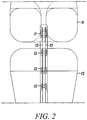
- Figure 2 shows a front view of the ACL reconstruction shown in Figures 1A and 1B .
- one exemplary direct tendon anchor 17 is used to secure the wrapped two strand hamstring graft 13 to the femur 11 by inserting the anchor through a drilled bone hole 18 created completely through the tibia 12 and partially through the femur 11.
- Three direct tendon anchors 15 are shown to secure the free ends of the hamstring graft strands 13 to the tibia 12. It should be noted than any number of direct tendon anchors (1 to 5) can be utilized to secure the graft within the drilled bone hole.
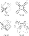
- Figures 3A to 3D show an isometric view, an end view, a shaded isometric view, and an isometric view, respectively, from the opposing end for one exemplary direct tendon anchor device 31 embodiment of the invention.
- This direct anchor embodiment 31 can be utilized to separately secure all discrete four strand ends of the hamstring ACL graft within a bone.
- the exemplary direct anchor embodiment 31 can be utilized to secure two strand tendons or single strand tendons, or grafts, within a drilled bone hole.
- one end 32 of the exemplary direct anchor embodiment is flared at the "clover leaf” extensions to partially penetrate into bone and increase the surface area of the contacting segment between the direct anchor embodiment and the surface of the bone defined by the drilled hole.
- the mid-section 33 between these "clover leaf” extensions are not flared to ensure the direct anchor is able to expand into a radially enlarged orientation during deployment, ensuring the direct anchor compresses the tendon against the bone surface defined by the drilled hole.
- the opposite end of the direct anchor embodiment 31 can incorporate an inward radius 36 to increase the surface area of contact between the tendon and direct anchor 31, and provide an atraumatic surface between the direct anchor 31 and tendon strands that loop around this end 35 of the direct anchor 31.
- This anchor embodiment 31 can be used to secure the proximal, looping end of the hamstring ACL graft within the femoral drilled bone hole or other sliding anchor applications where a tendon or graft is looped around the anchor.
- this anchor embodiment 31 can be used to secure tendon or grafts within drilled bone holes using the double tendon strand technique, as described above. During the double tendon strand technique, the tendon strand loops around this end of the direct tendon anchor wherein the radiused end 35 prevents damage to the tendon or graft caused by contact with the direct anchor 31.
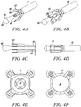
- FIG 4A shows an isometric view of an exemplary deployment instrument 41 according to the present invention.
- Figures 4B to 4F show an isometric view, a side-sectional view, a side view, a rear end view, and a front view, respectively, of the exemplary deployment instrument in Figure 4A with a direct anchor 42 supported for deployment.
- This exemplary deployment instrument 41 includes a movable anvil 43 that incorporates a transition from the pull rod 44 to the distal expanding dilator 45.
- the distal end of the dilator contains a radius 46 to prevent trauma to the tendon as the instrument 41 positions the direct anchor 42 and secures the tendon within the drilled bone hole while expanding the direct anchor 42.
- the deployment instrument 41 incorporates a holding shaft 47 to support the direct anchor 42 while the dilator 45 is actuated thereby expanding the direct anchor 42 into an enlarged orientation.
- the holding shaft 47 incorporates protrusions 48 that fit inside the "clover leaf” extensions of the direct anchor 42.
- Figures 5A and 5B show the exemplary deployment instrument 41 in Figures 4A to 4F with the dilator 45 retracted.
- Figure 5B shows a four strand tendon graft 51 (commonly used during the hamstring ACL reconstruction) positioned with each strand 51 held within a groove 49 of the direct anchor 41. It should be noted that two strands or a single strand looped or with one end free can be supported within the grooves 49 of the direct anchor 41.
- the innermost grooves 49 of the direct anchor 41 are deformed outwardly thereby compressing the tendons 51 supported within the grooves 49 against the surface defined by the drilled bone hole.
- the "clover leaf” extensions are further expanded outward into engagement with the bone thereby securing the direct anchor 41 thus the supported tendon within the drilled bone hole.
- Figure 6 shows an alternative direct anchor embodiment 61 where one end 62 of the direct anchor is flared throughout one edge.
- the opposite end 63 of the direct anchor 61 is straight.
- the flared end 62 can be flared along the entire periphery of the direct anchor 61, as shown; or it could be flared only at the "clover leaf” extensions as shown in Figures 3A to 3C with the mid region defined by the grooves straight to facilitate expansion of the direct anchor.
- the direct anchor embodiment 61 is expanded into an enlarged orientation, the tendon is compressed against the bone-drilled surface and the "clover leaf” extensions are pressed into the surface of the bone defined by the drilled bone hole.
- the flared end 62 increases the bond strength between the direct anchor 61 and the bone surface by increasing the surface area of contact between the bone and the anchor 61 and ensuring any tension applied to the bone anchor 61 is distributed over a large surface that deflects the applied forces in a non-axial direction to increase contact upon further deflection of the bone anchor.
- Figure 7 shows an isometric view of a substantially non-cylindrical direct anchor embodiment 71 designed to secure a single strand looped around the direct anchor 71, two strands looped around the direct anchor 71, or one or two tendon free ends to the surface defined by the drilled bone hole.
- This direct anchor embodiment 71 incorporates an inward radius along one end 72 to prevent trauma to looping tendon, or graft, segments.
- this anchor embodiment 71 enables the change of applied forces that compress the graft (e.g., tendon) against bone tissue versus the forces that the anchor 71 applies against the bone tissue required to ensure the pull-out forces are high enough that the anchor 71, thus the compressed graft, will not dislodge from the bone channel.
- These variable forces prevent abrading, tearing, or otherwise damaging the graft while deploying the anchor 71 or supporting the graft once the anchor 71 is affixed within the bone channel.
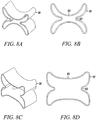
- Figures 8A and 8B show an isometric view and a top view of another substantially non-cylindrical direct anchor embodiment 81 of the present invention.
- Figures 8C and 8D show an isometric view and a top view of the direct anchor embodiment 81 shown in Figures 8A and 8B in an expanded orientation.
- the inner grooves 82 and 83 of the direct anchor 81 are expanded radially thereby causing the "butterfly" extensions to deform radially outward into engagement with the bone surface defined by the drilled hole.
- Figures 9A and 9B show a side and front view of a femur 91 with two strands 92 of a hamstring ACL graft looped around the exemplary substantially non-cylindrical direct anchor 71 of Figure 7 .
- the substantially non-cylindrical direct anchor embodiment of Figure 7 can be used to connect any looping (or free end) tendon or graft to the bone surface defined by the drilled hole 94.
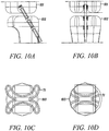
- Figures 10A to 10D show a side view, a front view, an end view, and a cross-sectional view of the substantially non-cylindrical direct anchors in Figures 7 and/or 8 used to secure an ACL graft at the femoral end 101 and the tibial end 102.
- the "butterfly" extensions of the direct anchor 71 are deflected into the surface 103 of the bone defined by the drilled hole to ensure engagement between the direct anchor 71 and the bone 101 or 102 as the direct anchor 71 is expanded with the deployment instrument 41.
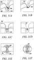
- Figures 11A to 11C show side-sectional views of exemplary steps that may be taken in positioning and securing an ACL graft 113 within a hole 112 drilled into the femur 111 using substantially non-cylindrical direct anchor embodiments 71 or 81 shown in Figures 7 and 8 .
- the ACL graft strands 113 are looped around the distal end of the direct anchor 71 and inserted through the bone hole 112 of the femur 111.
- the dilator 45 is actuated to expand the direct anchor 71 into the drilled bone hole 112.
- the direct bone anchor 71 compresses the tendon 113 against the surface of the femur 111 defined by the drilled hole 112 and engages the securing extensions of the direct anchor 71 against the bone surface to ensure the tendon 113 is secured in place as tension is applied.
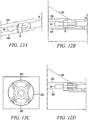
- Figures 12A to 12D show an isometric view, a side view, a cross-sectional view, and a side-sectional view of the deployment instrument 41 in Figure 4A with the substantially non-cylindrical direct anchor embodiment 71 of Figures 7 and 8 positioned for placement.
- the deployment instrument 41 is positioned between the strands 122 of the ACL graft free ends to secure the ACL graft 122 to the tibia 121.
- the dilator 45 is actuated thereby expanding the direct anchor 71 inside the drilled bone hole 123, compressing the tendon free ends 122 against the bone surface defined by the drilled hole 123 and engaging the securing extensions of the direct anchor 71 against the bone 121.
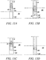
- Figures 13A to 13D show exemplary steps for deploying and attaching a strand of tendon or graft within a drilled bone hole.
- the deployment instrument 41 of Figure 4A is used to insert the looping strand 132 of tendon and the direct anchor 139 into a pre-drilled bone hole 133 in a bone 131.
- the dilator 45 is actuated, expanding the direct anchor 139 into engagement with the bone surface defined by the drilled hole 133 and compressing the tendon 132 against the bone.
- the deployment instrument 41 is removed, as shown in Figure 13C , leaving the tendon 132, or graft, secured within the bone hole 133 via the direct anchor 139, as shown in Figure 13D .
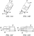
- FIGS 14A to 14D show two isometric views, a side view, and a side-sectional view, respectively, of an alternative deployment instrument embodiment 141 according to the present invention.
- This deployment instrument 141 uses an anvil 142 to support the direct anchor 143 while a shaft 144 incorporating an expansion transition is actuated and advanced relative to the direct anchor 143. Once actuated, the expansion shaft 144 is used to expand the direct anchor 143 into a radially enlarged orientation. Once fully expanded into the bone hole, the anvil 142 releases from the central lumen of the direct anchor 143 signaling full expansion of the direct anchor 143 thus completing attachment of the tendon(s) to the surface of the bone defined by the drilled hole. Until the direct anchor 143 is fully expanded, the anvil 142 supports the direct anchor 143 as the expansion shaft 144 continues to move axially further expanding the direct anchor 143.
- This exemplary deployment instrument embodiment 141 further incorporates a tendon positioner 145 that aids in placement of the tendon into the bone hole.
- this positioner 145 is a needle tip that punctures into the tendon and holds the tendon while it and the direct anchor 143 are placed into the bone hole.
- the anvil 142 may incorporate a central lumen through which a clamp or snare can be manipulated to grasp the tendon.
- two opposing metal clamping ribbons are spring loaded to engage and compress around the tendon while grasping the tendon for placement.
- a single wire or ribbon is looped outside the central lumen. As the snare is advanced, the loop opens and as the snare is retracted, the loop compresses against the tendon placed within the snare opening. Once secured, the grasping mechanism is release from the tendon and removed from the bone hole.
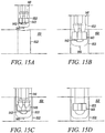
- Figures 15A to 15D show the exemplary deployment instrument 141 in Figures 14A to 14D used to place a segment of tendon 153 into a bone hole 152 and secure it by expanding the direct anchor 143 thereby engaging the anchor 143 to the surface of the bone 151 defined by the drilled hole 152 and compressing the tendon 153 against this surface to promote healing of the tendon 153 to the bone 151.
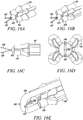
- Figures 16A to 16D show isometric views, a side view, and an end view, respectively, of the deployment instrument 141 in Figures 14A to 14D with the needle tip tendon engagement mechanism modified to a two ribbon wire 146 and 147 clamping mechanism.
- the spring-loaded clamping mechanism 146 and 147 As the spring-loaded clamping mechanism 146 and 147 is advanced beyond the central lumen of the anvil 142 it expands into an enlarged opening between the two distal ends of the clamping mechanism 146 and 147.
- the clamping mechanism 146 and 147 As the clamping mechanism 146 and 147 is placed over a tendon 145 or graft, as shown in Figure 16E , the clamping mechanism 146 and 147 is retracted thereby clamping the tendon 145 and engaging it to enable positioning the clamp 146 and 147 along with the supported direct anchor 143 into the drilled bone hole for attachment.
- Figures 17A to 17C show an isometric view, a side-sectional view, and a top view, respectively, of the substantially non-cylindrical direct anchor embodiment 71 in Figures 7 and 8 securing a segment of tendon 173 within a bone hole 172 of a bone 171.
- the tendon segment 173 loops around the distal end of the substantially non-cylindrical direct anchor 71 and fits within the opposing grooves.
- the grooves are deflected outward compressing the tendon 173 against the surface of the bone 171 defined by the drilled hole 172, and engaging the butterfly extensions of the direct anchor 71 to the bone surface thereby attaching the tendon 173 within the bone hole 172.
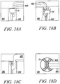
- Figures 18A to 18D show a side view, an isometric view, a side-sectional view, and a top view, respectively, of the substantially non-cylindrical direct anchor embodiment 71 shown in Figures 7 and 8 securing the free end of a tendon 183, or graft, within a bone hole 182 of a bone 181.
- the deployment instrument described above incorporates a grasping mechanism to grasp the free end of the tendon 183 and place the free end into the bone hole 182 such that the tendon 183 passes along one of the grooves in the direct anchor 71.
- the direct anchor 71 is expanded into the bone hole 182 to compress the tendon 183 against the surface of the bone 181 defined by the drilled hole and engage this surface with the extensions of the direct anchor.
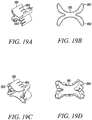
- Figures 19A and 19B show an isometric and a top view of an alternative substantially non-cylindrical direct anchor embodiment 191 that incorporates "butterfly" extensions 192 that engage the surface of the bone defined by the drilled hole, and slots 193 that create flaps 194 that, once positioned and actuated, engage either the tendon and/or the surface of the bone defined by the drilled hole to increase the bond strength between the substantially non-cylindrical direct anchor 191 and the tendon to the bone.
- Figures 19C and 19D show an isometric view and a top view of the substantially non-cylindrical direct anchor embodiment 191 in Figures 19A and 19B in an expanded orientation with the substantially non-cylindrical direct anchor 191 fully deformed to compress tendon against the surface of the bone defined by the drilled hole and engage the bone anchor to that surface.
- Figures 20A and 20B show isometric views of two alternative direct anchor embodiments 201 and 205 that incorporate a "clover leaf" proximal end 202 transitioning to a cone distal end 203.
- the embodiment of Figure 20A further incorporates loops 204 that are either connected to the distal end 203 or pass through the central lumen where they connect to another component of the anchor 201 or are incorporated as one or more snares to the deployment instrument, previously described.
- Figures 20C and 20D show an isometric view and a top view of the direct anchor embodiment 205 of Figure 20B in an unexpanded orientation.
- Figures 20E and 20F show an isometric view and a top view of the direct anchor embodiment 205 in Figures 20B to 20D in an expanded orientation.
- the proximal end 202 of the embodiment in Figure 20A would expand similar to that for the embodiment shown in Figures 20E and 20F .
- the inner grooves 208 are deflected outward whereby they partially straighten into a larger radius of curvature, as shown in Figures 20D and 20F .
- the "clover leaf” extensions 209 are radially expanded into engagement with the surface of the bone defined by the drilled hold. These extensions 209 also open up while the direct anchor 205 is deployed, however their preshaped radii of curvature are less than that for the grooves 208; therefore, any expansion of the direct anchor 205 straightens the grooves 208 before the extensions 209 open up. That way, the extensions 209 maintain their ability to engage the bone surface defined by the drilled hole.
- Figures 21A to 21D show a side-sectional view, a cross-sectional view oriented away from the bone axis, a cross-sectional view oriented towards the bone axis, and a top view, respectively, of the direct anchor 205 in Figure 20B to 20F with four strands 213 of tendon supported by the grooves 208 of the direct anchor 205.
- the four strand 213 engagement is common with the hamstring ACL reconstruction at a bone hole 212 in the tibial 211 attachment side.
- this direct anchor embodiment 205 may alternatively be used to secure one or two strands of tendon 213, or graft during double tendon strand or sliding anchor techniques.
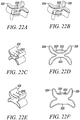
- Figures 22A and 22B, and 22C and 22D show two substantially non-cylindrical direct anchor embodiments 221 capable of being used during double tendon strand or sliding anchor techniques described above, as well as rotator cuff repair and suturing the tendon to the implant techniques.
- This substantially non-cylindrical direct anchor embodiment 221 incorporates offset openings 222 through which one or more suture strands can be inserted.
- the suture is secured to the direct anchor 221 as the openings 222 are deformed closed locking the suture in place.
- the grooves 223 are expanded outward thereby compressing any tendon positioned along the groove 222 against the surface of the bone defined by the drilled hole.
- the "butterfly" extensions 224 are expanded radially outward into engagement with this bone surface thereby securing the direct anchor 221 to the bone.
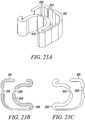
- Figures 23A to 23C show an isometric view, a bottom view and a top view, respectively, of an alternative substantially non-cylindrical direct anchor embodiment 231 according to the present invention.
- the substantially non-cylindrical direct anchor 231 incorporates a flex region 232 along which the substantially non-cylindrical direct anchor 231 (in this case fabricated from a resilient elastic member) can be compressed into a small diameter for insertion into the bone. Once positioned, this direct anchor 231 is released to expand towards its preformed configuration where it locks to the bone surface defined by the drilled hole and compresses the tendon against that surface.
- the substantially non-cylindrical direct anchor 231 may alternatively be deformable and manually expanded, via actuation with a deployment clamp, into an enlarged, deformed orientation whereby the direct anchor 231 engages the bone surface.
- Two notches 233 are incorporated in the direct anchor 231 for a clamp to temporarily engage the direct anchor 231 and enable manipulating the direct anchor 231 into a compressed or enlarged orientation.
- the cross-section of the direct anchor 231 resembles the cross-section of a cone such that the proximal wider edge can engage the surface of the bone defined by the drilled hole along the periphery of the direct anchor.
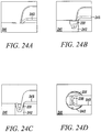
- Figures 24A to 24D show two side views, a side-sectional view, and a top view, respectively, of the substantially non-cylindrical direct anchor embodiment 231 in Figures 23A to 23C securing the free end of a tendon 243, or graft, within a bone hole 242 of a bone 241.
- This embodiment 231 enables clamping the tendon 243, or graft, in the central opening 238 defined by the "C" link and the outer link of the integrated direct anchor 231.
- the clamp deployment mechanism is used to enlarge this central opening 238 for positioning around the free end of the tendon 243 such that once positioned, the clamp is relaxed compressing the tendon 243 between the opposing links thereby engaging the tendon 243 to the direct anchor 231 for placement.
- the tendon 243 is positioned within the lumen 238 of the "C” link such that it can be compressed against the bone surface defined by the drilled hole 242 once deployed.
- Figures 25A to 25F show two top views, an isometric view, a cross-sectional view, a side view, and a side-sectional view, respectively, of the substantially non-cylindrical direct anchor embodiment 231 in Figures 23A to 23D securing an in-line segment of tendon 253 within a bone hole 252 of a bone 251.
- this substantially non-cylindrical direct anchor embodiment 231 is enlarged to engage a segment of tendon 253 such that the tendon 253 loops around the distal end of the direct anchor 231.
- the substantially non-cylindrical direct anchor 231 is compressed into a small diameter for positioning into a bone hole 252.
- the substantially non-cylindrical direct anchor 231 is released or manually enlarged to secure the substantially non-cylindrical direct anchor 231 to the surface of the bone 251 defined by the drilled hole 252 and compress the tendon 253 against that surface.
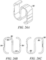
- Figures 26A to 26C show an isometric view, a bottom view, and a top view, respectively, of an alternative direct anchor embodiment 261.
- This embodiment also incorporates flex regions 262 along which the direct anchor 261 can be compressed or enlarged.
- the direct anchor 261 incorporates openings 263 through which tendon can be engaged during actuation of the direct anchor 261.
- opposing notches 264 along the outer "S" links are configured for a clamp to engage the "S" direct anchor 261 for compressing or expanding the direct anchor 261.
- Figures 27A to 27F show an isometric view, a side view, a shaded isometric view, a side-sectional view, a top view, a cross-sectional view, respectively, of the direct anchor embodiment 261 shown in Figures 26A to 26C with a tendon 273 looped around the distal link of the "S" direct anchor 261 positioned in a bone hole 272 of a bone 271.
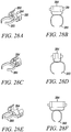
- Figures 28A and 28B show an isometric view and a side view of another exemplary substantially non-cylindrical direct anchor embodiment 281 that may also function as a clamp.
- This substantially non-cylindrical direct anchor embodiment 281 incorporates opposing engagement ears 282 through which a deployment actuator can engage the base of the direct anchor 281 for manipulation.
- clamp legs 283 are incorporated in the substantially non-cylindrical direct anchor 281 for engaging the tendon.
- This substantially non-cylindrical direct anchor 281 further incorporates a central flex region along which the base 284 of the direct anchor 281 can be compressed or expanded, thereby expanding or compressing the clamp legs 283.
- Figures 28C and 28D show the substantially non-cylindrical direct anchor embodiment 281 in Figures, 28A and 28B in a compressed orientation where the base is actuated into a compressed orientation such that the clamp legs 283 enlarge for grasping a tendon.
- the base 284 is expanded, as shown in Figures 28E and 28F .
- the direct anchor 281 increases compression of the tendon securing the tendon to the direct anchor 281 and the base 284 expands into engagement with the surface of the bone defined by the drilled hole.
- Figures 29A to 29F show two isometric views, two top views, a cross-sectional view, and a side-sectional view, respectively, of the substantially non-cylindrical direct anchor embodiment 281 in Figures 28A to 28F securing a segment of tendon 293, or graft, within a bone hole 292 of a bone 291.
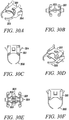
- FIGS 30A to 30C show an isometric view, a top view, and a side view, respectively, of an alternative substantially non-cylindrical direct anchor embodiment 301 according to the present invention.
- This substantially non-cylindrical direct anchor 301 incorporates a central opening 302 through which a dilation mechanism can be advanced to expand the direct anchor 301 into engagement with the surface of the bone defined by the drilled hole.
- Tabs 303 and 304 are also included in the direct anchor 301 to ensure attachment of the tendon to the anchor 301 and the anchor 301 to the bone hole.
- the central tabs 303 prevent movement of the tendon relative to the substantially non-cylindrical direct anchor 301 once positioned and expanded into engagement.
- the reverse tabs 304 prevent dislodgement of the substantially non-cylindrical direct anchor 301 from the bone hole once positioned and secured.
- Clamp legs 308 define an opening into which the tendon can be placed and supported during positioning of the tendon and direct anchor into the bone hole.
- Grooves 309 provide openings into which tendon strands can be placed and compressed against the surface of the bone defined by the drilled hole once the substantially non-cylindrical direct anchor 301 is expanded with the deployment instrument.
- Figures 30D to 30F show an isometric view, a top view, and a side view, respectively, of the embodiment shown in Figures 30A to 30C in an expanded orientation.
- Figures 31A to 31F show two isometric views, a side view, a side-sectional view, a top view, and a cross-sectional view, respectively, of the substantially non-cylindrical direct anchor embodiment 301 shown in Figures 30A to 30F securing a segment of tendon 313 within a bone hole 312 of a bone 311.
- Figures 32A to 32C show an isometric view, a side view, and a top view of another exemplary direct anchor embodiment 321 for securing a segment of tendon within a bone hole.
- Tabs 322 extending from the direct anchor 321 engage the surface of the bone defined by the drilled hole to secure the tendon and the direct anchor 321 within the bone hole.
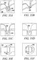
- Figures 33A to 33F show two isometric views, a side view, a side-sectional view, a top view, and a cross-sectional view, respectively, of the direct anchor 321 shown in Figures 32A to 32C securing a segment of tendon 333 within a bone hole 332 of a bone 331.
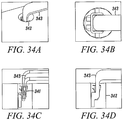
- Figures 34A to 34D show an isometric view, a top view, a side view, and a side-sectional view of another substantially non-cylindrical direct anchor 341 securing a free end of tendon 343 within a bone hole 342 of a bone 341.
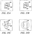
- Figures 35A to 35D show two isometric views, a side view, and a top view of an exemplary multiple component direct anchor embodiment 351 according to the present invention.
- This multiple component direct anchor 351 incorporates a central tip 352 around which the tendon loops and a proximal, radially expanding base 353 that expands as tension is applied to the central tip 352 thereby further expanding into engagement with the surface of bone defined by the drilled hole. Therefore, as tension is applied to the tendon, the central tip 352 is retracted thereby enlarging the diameter of the proximal base 353 which further engages the bone surface ensuring the tendon does not pull free from the bone hole.
- the proximal base 353 can consist of two mating pieces that are free moving, slide radially relative to each other, are hinged at one end with the other free to move so the base can radially expand, or otherwise define a radially expansion mechanism that enlarges in diameter as the central tip is retracted.
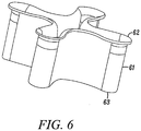
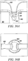
- Figures 36A and 36B show a side view and a top view of the direct anchor embodiment 351 shown in Figures 35A to 35D securing a segment of tendon 363 within a bone hole 362 of a bone 361.
- the tendon 363 loops inside the proximal base 353 and around the central tip 352 thereby securing the tendon 363 to the direct anchor 351 and ensuring that any tension on the tendon 363 causes the proximal base 353 to enlarge thus increasing the engagement of the direct anchor 351 to the bone 361 and ensuring integrity of the bone 361 to anchor 353 to tendon 363 bond.
- Figures 37A to 37D show a front view, an isometric view, a side view, and an end view of an alternative multiple component direct anchor embodiment 371 with a deployment instrument 375.
- the tendon loops around the central tip after passing within the lumen of the base.
- the deployment instrument 375 engages the proximal base and defines space along which the tendon can pass.
- Figures 38A and 38B show a side view and an isometric view of the deployment of the direct anchor embodiment 371 in Figures 37A to 37D .
- the deployment instrument 375 is used to position the tendon 383 and direct anchor 371, in an unstressed low profile orientation, into the bone hole 382.
- tension is applied either to the central tip 372 or to the tendon 383 thereby enlarging the proximal base 373 into engagement with the surface of the bone 381 defined by the drilled hole 382.
- the proximal base 373 secures the direct anchor 371 and the attached tendon 383 within the bone hole 382 such that any additional tension applied to the tendon 383 increases the engagement between the multiple component direct anchor 371 and the bone 381.
- FIGS 39A to 39F show isometric views, side view, and top view of an exemplary substantially non-cylindrical, multiple component tendon anchor embodiment 391 according to the present invention.
- this embodiment there are two implant components: (a) an outer anchor 392 and (b) an inner wedge piece 395.
- the outer anchor component's four side walls (arms) 393 can be deflected both inward and outward during deployment. Inward deflection may be allowed to make advancement of the device 391 into the bone hole easier, while outward deflection will anchor the implant 391 to the bone.
- the center arms 394 are in direct contact with a tendon which is aligned and looped around the distal end of the implant 391.
- the flattened or curvilinear shape of the center arms 394 is designed to optimize the implant to tendon contact area, which in turn increases the tendon to bone contact area.
- the extended distal elements (anchor claw) 396 are included to aid in the alignment of the tendon.
- the lateral arms 397 directly contact the bone surface and can have various protrusions or extensions 398 that anchor the implant 391 into the bone.
- the slots 399 between each of the arms 397 allow each arm to function and deflect independently to the adjacent arm. Moreover, these slots 399 allow for the adjustable expansion of the implant.
- the wedge piece component 395 of the implant includes a taper design with tabs 3951 that engage the outer anchor component 392 when inserted and advanced.
- the wedge shape of the component 395 expands the outer anchor arms 397 radially outward as it is advanced distally, simultaneously pushing the tendon against the bone surface and anchoring the implant 391 to the bone by expanding the lateral walls 397 into the bone.
- the tendon is looped around and positioned over the implant 391.
- the tendon - implant is advanced through the bone hole. Once in position, the anchor 391 is deployed by advancing the wedge 395 to secure the anchor 391 to the bone surface and compress the tendon to the bone surface as defined by the bone hole.
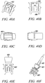
- Figure 40A to 40F show isometric views, side view, and top view of an exemplary substantially non-cylindrical, multiple component tendon anchor embodiment 401 according to the present invention, including an outer anchor 402 and a wedge 403.
- This embodiment 401 is a derivative of that described in Figures 39A to 39F with a smaller variation in the distal anchor claw 406 used for positioning and alignment of the tendon.
- Variation in the position, shape, and number of tabs or facets on the arms of the implant can be used to optimize the anchoring of the implant to the bone as well as improve the tendon to bone surface contact.
- the profile of the implant arms may also be an embodiment that has an "I" beam cross section as compared to a rectangular cross section shown.
- This "I" beam shape would allow a deeper center channel for the positioning and alignment of the tendon as well as provide a larger surface area contact between the bone and the anchor surface.
- the lateral arms of the implant need not be limited to rectangular cross section, but other embodiments may also have a curvilinear shape similar to that of the bone hole. The intention of this curvilinear shape variation would be to increase the surface area contact of the bone to the implant.
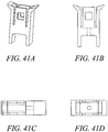
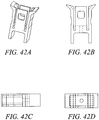
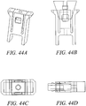
- Figures 41 - 44 show different variations of the outer implant. Variations in the angle and shape of the anchor arm slot can be achieved with different embodiments. In these embodiments, the angle of the slot will affect the stress distribution along the outer anchor and at the base of the arms of the outer anchor. Various embodiments can include different slot angles to minimize the stresses on the implant during expansion and well as pullout. By orienting the slot angles or tapering the slots, one can optimize the axial force transfer of the implant, resulting in potentially higher pullout strength by reducing the failure of the system due to fracture of the anchor implant. The embodiments included in this application include optimization of design with respect to the thickness of the arms, the expandability of the implant, the strength of fixation required for the anchor, the fracture resistance of the anchor, manufacturability and overall size.
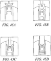
- Figs. 45A to 45C show side view of anchor delivery, inner wedge advancement and deployment of the substantially non-cylindrical tendon anchoring embodiment shown in Figs 42A to 42D .
- the mechanism for deployment of this embodiment, as well as the other exemplary embodiments shown in Figures 41-44 closely relate to the mechanism shown with respect to Figures 39 and 40 .
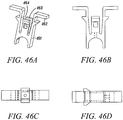
- Figs. 46A to 46D show isometric views, side view, and top view of an exemplary substantially non-cylindrical, multiple component tendon anchor embodiment 461 according to the present invention.
- Exemplary uses for this embodiment include cortical bone shell and trabecular bone interface as an anchoring advantage. All elements of this embodiment 461 include those described in Figures 40-45 .
- the variation described here include an expanded lateral flange 462, which is intended to abut the outer surface of the cortical bone at the bone hole surface, and a lower profile lateral flange 463 just distal to the expanded lateral flange 462, which is intended to abut the inner surface of the cortical bone surface.
- the gap between the two flanges 464 can vary between implant embodiments to include the range of cortical bone thicknesses expected at each implant site. Note that the lower profile flange 463 need not abut the inner surface of the cortical bone, but may act as described in previous embodiment wherein the arm extension is expanded into the bone surface, anchoring the implant into position.
- the basic premise of this design is to use the cortical bone cortex to provide additional fixation support.
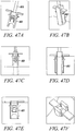
- Figs. 47A to 47F show side view of anchor delivery, inner wedge advancement and deployment of the tendon anchoring embodiment 461 shown in Figs 46A to 46D .
- Such mode of delivery using a deployment device 465 and technique used is substantially similar to that described with respect to Figures 39 and 40 .
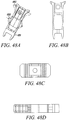
- Figs. 48A to 48D show isometric views, side view, and top view of an exemplary substantially non-cylindrical, multiple component tendon anchor embodiment 481 according to the invention as claimed with two levels of expanding sections.
- the proximal end 482 of the anchor implant is a similar embodiment to that described in Figures 40-47 .
- An additional embodiment is included here with a mid-section 483 which is expandable upon deployment of the implant. Specifically, once the implant 481 is in position and as the wedge is advanced to expand the lateral arms, the center section 483 will collapse and expand outward. Additional facets can be added on the surface of the mid-section 483 to promote anchoring in the bone.
- the resulting implant structure 481 in this embodiment is intended to provide two levels of implant fixation in the bone hole.
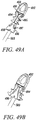
- FIGs. 49A and 49B show another exemplary embodiment of the present invention as a multi-piece anchor unit 491.
- An anchor portion 492 has a tendon receiving portion 493 and a pair of pivoting arms 494.
- the pivoting arms 494 may include tabs 495 that assist in the securing of the anchor portion 492 within a bone hole.
- a separating wedge 496 is shaped to fit and separate the pair of pivoting arms 494 and can be made thicker or bulbous in the middle so that the tendons can be compressed more against the bone wall.
- Locking tabs 497 positioned on the exterior portion of the separating wedge 496 assist in the locking of the separating wedge 496 with mating tabs located inside of the pivoting arms 494.
- a deployment device 501 may be used to deploy the anchor unit 491 within a bone hole in a bone.
- the deployment device 501 includes a trigger 502 that is used to push the tube 503 into the separating wedge 496.
- deployment is achieved by having a threaded rod screw into a threaded hole 499 in the body of the wedge 492, while the tube 503 pushes the wedge 496 into place by using the trigger 502, thus spreading the pivoting arms 494 outward and into the bone.
- the threaded rod is unscrewed via the wheel 504 at the back of the deployment device 501, releasing the anchor unit 491 from the deployment device 501.
- Anchor and deployment instrument components can incorporate elastic properties or be deformable.
- the anchor or deployment instrument components can be fabricated from various materials [e.g., shape memory alloys (e.g., nickel titanium (Nitinol)), shape memory polymers, polymers (e.g., PTFE, polyurethane, urethane, silicone, polyimide, polypropylene, Polylactic Acid, Polyglycolic Acid, or other thermoset or thermoplastic, or elastomeric materials), and metal or alloys (e.g., titanium, CoCrMo, stainless steel, etc)].
- the device anchor components can be resorbable, in other embodiments, the device components will have limited or no resorption characteristics.
- the anchor components described herein be made in part or solely of one material.
- the components of the anchors or deployment instruments can be composed of metal and/or polymer components fabricated into composite devices.
- low surface area and thin metal or metal alloy components can be insert molded with a polymer (e.g., polypropylene) to produce a composite device.
- Some embodiments may include parts that are resorbable and some that are not. Fabrication of these components can be performed using techniques familiar with manufacturing methods by those skilled in the art of metals, polymers, shape memory alloys, shape memory polymers, or composite materials. Sample techniques will include but are not limited to extrusion, casting, press-forging, rolling, or pressing methods for the fabrication of parts for the above materials.
- the use of techniques related to modification of polymer chemistry to adjust the shape memory characteristics related to thermal conditions and elastic properties of the polymer will be utilized.
- shape memory metal materials one having ordinary skill in the art will utilize the thermal characteristics of the specified composition to fabricate components with the geometry and features required for the device component. Proper thermal forming and quenching is required to process the material and is generally known to someone skilled in the art of using, processing, and fabricating components out of shape memory materials.
- several components may require parts using standard machining techniques typically known to someone skilled in the art of machining. For example, use of CNC, EDM, laser cutting, water jet cutting, polishing methods, and other machining techniques.
- Several embodiments may also require bonding or welding of components and include adhesives, laser welding, soldering, or other means of attachment.
- Anchor components that include spikes or tabs can be fabricated from any stock materials typically known to those having ordinary skill in the art of medical device manufacturing. Attachment of other components to these embodiments can be performed by tying, welding, bonding, clamping, embedding, or use of other such means. In some embodiments, these anchors can be mechanically polished or electropolished to produce smooth surfaces.
- Various embodiments of the clip components described can be coated with or encapsulated with a covering of a polymer material that can allow for the use of anti-proliferative, antibiotic, angiogenic, growth factors, anti-cancer, or other pharmacological substances that may provide a benefit related to inhibiting or promoting biological proliferation. These substances would be loaded into the encapsulating coatings and be allowed to elute into the surrounding matrix, tissues, or space that it sits. The time course of delivery can be tailored to the intended application by varying the polymer or the characteristics of the coating. Such coatings with pharmacological substances can act as anti-proliferative treatments or can aid in the healing response of the tissue being treated. Furthermore, these coatings can act to reduce the local coagulation or hyperplastic response near the anchor.
Applications Claiming Priority (3)
| Application Number | Priority Date | Filing Date | Title |
|---|---|---|---|
| US62877404P | 2004-11-18 | 2004-11-18 | |
| US67151005P | 2005-04-15 | 2005-04-15 | |
| PCT/US2005/041924 WO2006055823A2 (en) | 2004-11-18 | 2005-11-18 | Devices, systems and methods for material fixation |
Publications (3)
| Publication Number | Publication Date |
|---|---|
| EP1824395A2 EP1824395A2 (en) | 2007-08-29 |
| EP1824395A4 EP1824395A4 (en) | 2012-07-18 |
| EP1824395B1 true EP1824395B1 (en) | 2019-07-03 |
Family
ID=36407790
Family Applications (1)
| Application Number | Title | Priority Date | Filing Date |
|---|---|---|---|
| EP05851848.1A Not-in-force EP1824395B1 (en) | 2004-11-18 | 2005-11-18 | Devices and systems for material fixation |
Country Status (5)
| Country | Link |
|---|---|
| US (2) | US7651528B2 (ja) |
| EP (1) | EP1824395B1 (ja) |
| JP (2) | JP4603047B2 (ja) |
| AU (1) | AU2005306450B9 (ja) |
| WO (1) | WO2006055823A2 (ja) |
Families Citing this family (116)
| Publication number | Priority date | Publication date | Assignee | Title |
|---|---|---|---|---|
| US7195642B2 (en) * | 2001-03-13 | 2007-03-27 | Mckernan Daniel J | Method and apparatus for fixing a graft in a bone tunnel |
| IL164591A0 (en) | 2004-10-14 | 2005-12-18 | Hernia repair device | |
| US8298262B2 (en) | 2006-02-03 | 2012-10-30 | Biomet Sports Medicine, Llc | Method for tissue fixation |
| US8088130B2 (en) | 2006-02-03 | 2012-01-03 | Biomet Sports Medicine, Llc | Method and apparatus for coupling soft tissue to a bone |
| US9017381B2 (en) | 2007-04-10 | 2015-04-28 | Biomet Sports Medicine, Llc | Adjustable knotless loops |
| US9801708B2 (en) | 2004-11-05 | 2017-10-31 | Biomet Sports Medicine, Llc | Method and apparatus for coupling soft tissue to a bone |
| US8840645B2 (en) | 2004-11-05 | 2014-09-23 | Biomet Sports Medicine, Llc | Method and apparatus for coupling soft tissue to a bone |
| US8137382B2 (en) | 2004-11-05 | 2012-03-20 | Biomet Sports Medicine, Llc | Method and apparatus for coupling anatomical features |
| US8303604B2 (en) | 2004-11-05 | 2012-11-06 | Biomet Sports Medicine, Llc | Soft tissue repair device and method |
| US7905904B2 (en) | 2006-02-03 | 2011-03-15 | Biomet Sports Medicine, Llc | Soft tissue repair device and associated methods |
| US8118836B2 (en) | 2004-11-05 | 2012-02-21 | Biomet Sports Medicine, Llc | Method and apparatus for coupling soft tissue to a bone |
| US8128658B2 (en) | 2004-11-05 | 2012-03-06 | Biomet Sports Medicine, Llc | Method and apparatus for coupling soft tissue to bone |
| US7749250B2 (en) | 2006-02-03 | 2010-07-06 | Biomet Sports Medicine, Llc | Soft tissue repair assembly and associated method |
| US8361113B2 (en) | 2006-02-03 | 2013-01-29 | Biomet Sports Medicine, Llc | Method and apparatus for coupling soft tissue to a bone |
| US7909851B2 (en) | 2006-02-03 | 2011-03-22 | Biomet Sports Medicine, Llc | Soft tissue repair device and associated methods |
| US7658751B2 (en) | 2006-09-29 | 2010-02-09 | Biomet Sports Medicine, Llc | Method for implanting soft tissue |
| US8998949B2 (en) | 2004-11-09 | 2015-04-07 | Biomet Sports Medicine, Llc | Soft tissue conduit device |
| JP4603047B2 (ja) * | 2004-11-18 | 2010-12-22 | カイエン メディカル インコーポレイテッド | 材料固定装置 |
| WO2006108114A2 (en) * | 2005-04-01 | 2006-10-12 | The Regents Of The University Of Colorado | A graft fixation device and method |
| US8597327B2 (en) | 2006-02-03 | 2013-12-03 | Biomet Manufacturing, Llc | Method and apparatus for sternal closure |
| US11311287B2 (en) | 2006-02-03 | 2022-04-26 | Biomet Sports Medicine, Llc | Method for tissue fixation |
| US8771352B2 (en) | 2011-05-17 | 2014-07-08 | Biomet Sports Medicine, Llc | Method and apparatus for tibial fixation of an ACL graft |
| US9078644B2 (en) | 2006-09-29 | 2015-07-14 | Biomet Sports Medicine, Llc | Fracture fixation device |
| US11259792B2 (en) | 2006-02-03 | 2022-03-01 | Biomet Sports Medicine, Llc | Method and apparatus for coupling anatomical features |
| US8506597B2 (en) | 2011-10-25 | 2013-08-13 | Biomet Sports Medicine, Llc | Method and apparatus for interosseous membrane reconstruction |
| US8936621B2 (en) | 2006-02-03 | 2015-01-20 | Biomet Sports Medicine, Llc | Method and apparatus for forming a self-locking adjustable loop |
| US8251998B2 (en) | 2006-08-16 | 2012-08-28 | Biomet Sports Medicine, Llc | Chondral defect repair |
| US8562645B2 (en) | 2006-09-29 | 2013-10-22 | Biomet Sports Medicine, Llc | Method and apparatus for forming a self-locking adjustable loop |
| US8652172B2 (en) | 2006-02-03 | 2014-02-18 | Biomet Sports Medicine, Llc | Flexible anchors for tissue fixation |
| US8801783B2 (en) | 2006-09-29 | 2014-08-12 | Biomet Sports Medicine, Llc | Prosthetic ligament system for knee joint |
| US9149267B2 (en) | 2006-02-03 | 2015-10-06 | Biomet Sports Medicine, Llc | Method and apparatus for coupling soft tissue to a bone |
| US8968364B2 (en) | 2006-02-03 | 2015-03-03 | Biomet Sports Medicine, Llc | Method and apparatus for fixation of an ACL graft |
| US9538998B2 (en) | 2006-02-03 | 2017-01-10 | Biomet Sports Medicine, Llc | Method and apparatus for fracture fixation |
| US8562647B2 (en) | 2006-09-29 | 2013-10-22 | Biomet Sports Medicine, Llc | Method and apparatus for securing soft tissue to bone |
| US8652171B2 (en) | 2006-02-03 | 2014-02-18 | Biomet Sports Medicine, Llc | Method and apparatus for soft tissue fixation |
| US10517587B2 (en) | 2006-02-03 | 2019-12-31 | Biomet Sports Medicine, Llc | Method and apparatus for forming a self-locking adjustable loop |
| US8574235B2 (en) | 2006-02-03 | 2013-11-05 | Biomet Sports Medicine, Llc | Method for trochanteric reattachment |
| JP5204755B2 (ja) | 2006-03-20 | 2013-06-05 | カイエン メディカル インコーポレイテッド | 材料固定のための装置、システム、及び方法 |
| US8672969B2 (en) | 2006-09-29 | 2014-03-18 | Biomet Sports Medicine, Llc | Fracture fixation device |
| US9918826B2 (en) | 2006-09-29 | 2018-03-20 | Biomet Sports Medicine, Llc | Scaffold for spring ligament repair |
| US11259794B2 (en) | 2006-09-29 | 2022-03-01 | Biomet Sports Medicine, Llc | Method for implanting soft tissue |
| US8500818B2 (en) | 2006-09-29 | 2013-08-06 | Biomet Manufacturing, Llc | Knee prosthesis assembly with ligament link |
| WO2008073588A2 (en) * | 2006-10-24 | 2008-06-19 | Cayenne Medical, Inc. | Methods and systems for material fixation |
| CA2670673C (en) | 2006-11-27 | 2015-11-24 | Surgical Structure Ltd. | A device especially useful for hernia repair surgeries and methods thereof |
| US8617185B2 (en) * | 2007-02-13 | 2013-12-31 | P Tech, Llc. | Fixation device |
| WO2008112912A2 (en) * | 2007-03-13 | 2008-09-18 | Smith & Nephew, Inc. | Internal fixation devices |
| AU2008242972B2 (en) * | 2007-04-19 | 2014-05-22 | Smith & Nephew, Inc. | Prosthetic implants |
| EP3225209B1 (en) | 2007-10-17 | 2023-05-24 | Davol, Inc. | Fixating means between a mesh and mesh deployment means especially useful for hernia repair surgeries |
| US20090281581A1 (en) | 2008-05-06 | 2009-11-12 | Berg Jeffery H | Method and device for securing sutures to bones |
| ES2576079T3 (es) | 2008-05-07 | 2016-07-05 | Davol Inc. | Método y aparato para reparar una hernia |
| US8858565B1 (en) | 2008-05-08 | 2014-10-14 | Cayenne Medical, Inc. | Inserter for soft tissue or bone-to-bone fixation device and methods |
| US8123806B1 (en) | 2008-05-09 | 2012-02-28 | Cayenne Medical, Inc | Method of tensioning a tissue graft having suture bundles using a cleated bar |
| KR20110033199A (ko) * | 2008-06-19 | 2011-03-30 | 신세스 게엠바하 | 뼈 스크류 퍼처스 증강 임플란트, 시스템 및 기술 |
| US8069858B2 (en) * | 2008-07-24 | 2011-12-06 | Medshape Solutions, Inc. | Method and apparatus for deploying a shape memory polymer |
| US20100170521A1 (en) * | 2008-07-24 | 2010-07-08 | Medshape Solutions, Inc. | Method and apparatus for deploying a shape memory polymer |
| US8430933B2 (en) * | 2008-07-24 | 2013-04-30 | MedShape Inc. | Method and apparatus for deploying a shape memory polymer |
| WO2010028324A2 (en) * | 2008-09-08 | 2010-03-11 | Revolutionary Surgical Device, Llc | Knotless suture anchors |
| ES2813298T3 (es) | 2008-11-21 | 2021-03-23 | Bard Inc C R | Prótesis de reparación de tejidos blandos y dispositivo expansible |
| US20100145451A1 (en) | 2008-12-04 | 2010-06-10 | Derek Dee | Joint support and subchondral support system |
| US10610364B2 (en) | 2008-12-04 | 2020-04-07 | Subchondral Solutions, Inc. | Method for ameliorating joint conditions and diseases and preventing bone hypertrophy |
| US8523902B2 (en) | 2009-01-30 | 2013-09-03 | Kfx Medical Corporation | System and method for attaching soft tissue to bone |
| US8206446B1 (en) | 2009-03-10 | 2012-06-26 | Cayenne Medical, Inc. | Method for surgically repairing a damaged ligament |
| US8617241B2 (en) | 2009-03-31 | 2013-12-31 | Imds Corporation | Double bundle ACL repair |
| US8535377B2 (en) | 2009-03-31 | 2013-09-17 | Imds Corporation | Double bundle ACL repair system |
| EP3034022B1 (en) | 2009-04-17 | 2018-08-29 | Shane Barwood | Tenodesis system |
| US8343227B2 (en) | 2009-05-28 | 2013-01-01 | Biomet Manufacturing Corp. | Knee prosthesis assembly with ligament link |
| US9364276B2 (en) | 2009-07-09 | 2016-06-14 | Smith & Nephew, Inc | Tissue graft anchor assembly and instrumentation for use therewith |
| JP5710609B2 (ja) * | 2009-07-09 | 2015-04-30 | スミス アンド ネフュー インコーポレーテッド | 軟質組織移植片アンカー、組織移植片アンカーアセンブリ及びキット |
| US20110112558A1 (en) * | 2009-10-02 | 2011-05-12 | OC2, LLC, a Massachusetts limited liability company | Tissue fixation system with single component anchor |
| EP4368148A2 (en) | 2009-10-13 | 2024-05-15 | CONMED Corporation | System for securing tissue to bone |
| US8449612B2 (en) | 2009-11-16 | 2013-05-28 | Arthrocare Corporation | Graft pulley and methods of use |
| CA2813581A1 (en) | 2010-10-05 | 2012-04-12 | C. R. Bard, Inc. | Soft tissue repair prosthesis and expandable device |
| US9044313B2 (en) | 2010-10-08 | 2015-06-02 | Kfx Medical Corporation | System and method for securing tissue to bone |
| US10251754B2 (en) * | 2011-01-05 | 2019-04-09 | Peter Forsell | Knee joint device |
| US9427493B2 (en) | 2011-03-07 | 2016-08-30 | The Regents Of The University Of Colorado | Shape memory polymer intraocular lenses |
| US20140128983A1 (en) * | 2011-03-14 | 2014-05-08 | Topsfield Medical Gmbh | Implantable glenoid prostheses |
| EP2696780B1 (en) | 2011-04-13 | 2018-08-01 | ConMed Corporation | System for securing tissue to bone |
| GB201106434D0 (en) | 2011-04-15 | 2011-06-01 | Xiros Ltd | Implantable surgical cord anchor manufactured by rapid processing |
| US9775597B2 (en) | 2011-10-04 | 2017-10-03 | Conmed Corporation | Dual expansion anchor |
| US8968402B2 (en) | 2011-10-18 | 2015-03-03 | Arthrocare Corporation | ACL implants, instruments, and methods |
| US9357991B2 (en) | 2011-11-03 | 2016-06-07 | Biomet Sports Medicine, Llc | Method and apparatus for stitching tendons |
| US9370350B2 (en) | 2011-11-10 | 2016-06-21 | Biomet Sports Medicine, Llc | Apparatus for coupling soft tissue to a bone |
| US9381013B2 (en) | 2011-11-10 | 2016-07-05 | Biomet Sports Medicine, Llc | Method for coupling soft tissue to a bone |
| US9357992B2 (en) | 2011-11-10 | 2016-06-07 | Biomet Sports Medicine, Llc | Method for coupling soft tissue to a bone |
| KR102174538B1 (ko) | 2011-12-14 | 2020-11-05 | 디퍼이 신테스 프로덕츠, 인코포레이티드 | 골절부를 가로지른 압박용 장치 |
| US9192369B2 (en) | 2012-03-30 | 2015-11-24 | Depuy Mitek, Llc | Stacked plate suture anchor |
| WO2014055765A1 (en) * | 2012-10-05 | 2014-04-10 | Kfx Medical Corporation | System and method for tissue capture & anchoring |
| EP2911613B1 (en) * | 2012-10-23 | 2017-03-15 | Cayenne Medical, Inc. | Methods and systems for material fixation |
| US9056003B2 (en) * | 2013-01-25 | 2015-06-16 | Smith & Nephew, Inc. | Tissue graft fixation |
| US9757119B2 (en) | 2013-03-08 | 2017-09-12 | Biomet Sports Medicine, Llc | Visual aid for identifying suture limbs arthroscopically |
| JP2016515005A (ja) | 2013-03-14 | 2016-05-26 | ケーエフエックス・メディカル・エルエルシー | 組織捕捉骨アンカ |
| US9918827B2 (en) | 2013-03-14 | 2018-03-20 | Biomet Sports Medicine, Llc | Scaffold for spring ligament repair |
| EP2967551B1 (en) | 2013-03-15 | 2018-05-23 | ConMed Corporation | System for securing tissue to bone |
| US9301832B2 (en) | 2013-08-01 | 2016-04-05 | Christopher Sterling Pallia | Tendon anchor and method of using same |
| US10136886B2 (en) | 2013-12-20 | 2018-11-27 | Biomet Sports Medicine, Llc | Knotless soft tissue devices and techniques |
| US9980715B2 (en) | 2014-02-05 | 2018-05-29 | Trinity Orthopedics, Llc | Anchor devices and methods of use |
| US10064670B2 (en) | 2014-05-12 | 2018-09-04 | DePuy Synthes Products, Inc. | Sacral fixation system |
| CA2949060A1 (en) | 2014-05-12 | 2015-11-19 | DePuy Synthes Products, Inc. | Sacral fixation system |
| US9615822B2 (en) | 2014-05-30 | 2017-04-11 | Biomet Sports Medicine, Llc | Insertion tools and method for soft anchor |
| US9700291B2 (en) | 2014-06-03 | 2017-07-11 | Biomet Sports Medicine, Llc | Capsule retractor |
| US10039543B2 (en) | 2014-08-22 | 2018-08-07 | Biomet Sports Medicine, Llc | Non-sliding soft anchor |
| US10751161B2 (en) | 2014-10-23 | 2020-08-25 | Medos International Sárl | Biceps tenodesis anchor implants |
| US10729419B2 (en) | 2014-10-23 | 2020-08-04 | Medos International Sarl | Biceps tenodesis implants and delivery tools |
| US10034742B2 (en) | 2014-10-23 | 2018-07-31 | Medos International Sarl | Biceps tenodesis implants and delivery tools |
| US10076374B2 (en) | 2014-10-23 | 2018-09-18 | Medos International Sárl | Biceps tenodesis delivery tools |
| US10856966B2 (en) * | 2014-10-23 | 2020-12-08 | Medos International Sarl | Biceps tenodesis implants and delivery tools |
| US9955980B2 (en) | 2015-02-24 | 2018-05-01 | Biomet Sports Medicine, Llc | Anatomic soft tissue repair |
| US9974534B2 (en) | 2015-03-31 | 2018-05-22 | Biomet Sports Medicine, Llc | Suture anchor with soft anchor of electrospun fibers |
| US9693856B2 (en) | 2015-04-22 | 2017-07-04 | DePuy Synthes Products, LLC | Biceps repair device |
| WO2016191416A1 (en) * | 2015-05-27 | 2016-12-01 | Marino James F | Anchor devces and methods of use |
| US11039927B2 (en) | 2015-11-25 | 2021-06-22 | Subchondral Solutions, Inc. | Methods, systems and devices for repairing anatomical joint conditions |
| US10231823B2 (en) | 2016-04-08 | 2019-03-19 | Medos International Sarl | Tenodesis implants and tools |
| US10231824B2 (en) | 2016-04-08 | 2019-03-19 | Medos International Sárl | Tenodesis anchoring systems and tools |
| CA2995787A1 (en) | 2017-02-22 | 2018-08-22 | Stryker Corporation | Fixation member with separate eyelet and methods of use thereof |
| WO2020033840A1 (en) * | 2018-08-10 | 2020-02-13 | Conmed Corporation | Tenodesis fixation device |
| US11903813B2 (en) | 2019-04-15 | 2024-02-20 | Kevin L. Harreld | Intraosseous screw with cortical window and system and method for associating soft tissue with bone |
Citations (2)
| Publication number | Priority date | Publication date | Assignee | Title |
|---|---|---|---|---|
| FR2678823A1 (fr) * | 1991-07-11 | 1993-01-15 | Legrand Jean Jacques | Dispositif de renforcement d'un ligament au cours d'une plastie ligamentaire. |
| WO1996005783A1 (en) * | 1994-08-22 | 1996-02-29 | Li Medical Technologies, Inc. | Anchor and method for securement into a bore |
Family Cites Families (151)
| Publication number | Priority date | Publication date | Assignee | Title |
|---|---|---|---|---|
| US3708883A (en) | 1971-01-04 | 1973-01-09 | S Flander | Dental implant and method for using the same |
| FR2165159A5 (ja) | 1971-12-21 | 1973-08-03 | Talan Maryan | |
| JPS6021537Y2 (ja) | 1979-06-12 | 1985-06-27 | 日産自動車株式会社 | 連結具 |
| GB2084468B (en) | 1980-09-25 | 1984-06-06 | South African Inventions | Surgical implant |
| CN1006954B (zh) | 1985-03-11 | 1990-02-28 | 阿图尔·费希尔 | 用于骨接合术的紧固元件 |
| US4711232A (en) | 1985-07-12 | 1987-12-08 | Artur Fischer | Bone fastener and method of installing same |
| US4744793A (en) * | 1985-09-06 | 1988-05-17 | Zimmer, Inc. | Prosthetic ligament connection assembly |
| US4708132A (en) | 1986-01-24 | 1987-11-24 | Pfizer-Hospital Products Group, Inc. | Fixation device for a ligament or tendon prosthesis |
| US4738255A (en) | 1986-04-07 | 1988-04-19 | Biotron Labs, Inc. | Suture anchor system |
| GB8622563D0 (en) | 1986-09-19 | 1986-10-22 | Amis A A | Artificial ligaments |
| US4772286A (en) | 1987-02-17 | 1988-09-20 | E. Marlowe Goble | Ligament attachment method and apparatus |
| US4828562A (en) | 1988-02-04 | 1989-05-09 | Pfizer Hospital Products Group, Inc. | Anterior cruciate ligament prosthesis |
| US5108443A (en) | 1989-04-25 | 1992-04-28 | Medevelop Ab | Anchoring element for supporting a joint mechanism of a finger or other reconstructed joint |
| US4955910A (en) | 1989-07-17 | 1990-09-11 | Boehringer Mannheim Corporation | Fixation system for an elongated prosthesis |
| US5004474A (en) | 1989-11-28 | 1991-04-02 | Baxter International Inc. | Prosthetic anterior cruciate ligament design |
| US5139520A (en) | 1990-01-31 | 1992-08-18 | American Cyanamid Company | Method for acl reconstruction |
| WO1991016020A1 (en) | 1990-04-26 | 1991-10-31 | Danninger Medical Technology, Inc. | Transpedicular screw system and method of use |
| US5239650A (en) | 1990-05-21 | 1993-08-24 | International Business Machines Corporation | Preemptive demount in an automated storage library |
| US5037422A (en) | 1990-07-02 | 1991-08-06 | Acufex Microsurgical, Inc. | Bone anchor and method of anchoring a suture to a bone |
| US5236445A (en) | 1990-07-02 | 1993-08-17 | American Cyanamid Company | Expandable bone anchor and method of anchoring a suture to a bone |
| US5258016A (en) | 1990-07-13 | 1993-11-02 | American Cyanamid Company | Suture anchor and driver assembly |
| DE69127977T2 (de) | 1990-09-04 | 1998-09-17 | Smith & Nephew Inc N D Ges D S | Chirurgische schraube |
| US5725529A (en) | 1990-09-25 | 1998-03-10 | Innovasive Devices, Inc. | Bone fastener |
| ES2129413T3 (es) | 1990-09-25 | 1999-06-16 | Innovasive Devices Inc | Elemento de fijacion a huesos. |
| US7074203B1 (en) * | 1990-09-25 | 2006-07-11 | Depuy Mitek, Inc. | Bone anchor and deployment device therefor |
| FR2671717A1 (fr) * | 1991-01-17 | 1992-07-24 | Asa Laboratoires Prothaid | Piton a expansion pour la fixation d'une prothese ligamentaire sur la paroi corticale d'un os. |
| DE4106823C1 (ja) | 1991-03-04 | 1992-06-25 | Liebscher Kunststofftechnik, 8032 Graefelfing, De | |
| GB9105957D0 (en) | 1991-03-21 | 1991-05-08 | Seedhom Bahaa B | Implantable fixing device |
| US5354298A (en) | 1991-03-22 | 1994-10-11 | United States Surgical Corporation | Suture anchor installation system |
| US5480403A (en) * | 1991-03-22 | 1996-01-02 | United States Surgical Corporation | Suture anchoring device and method |
| US5720753A (en) * | 1991-03-22 | 1998-02-24 | United States Surgical Corporation | Orthopedic fastener |
| CA2063159C (en) | 1991-03-22 | 1999-06-15 | Thomas W. Sander | Orthopedic fastener |
| FR2676356A1 (fr) | 1991-05-13 | 1992-11-20 | Cendis Medical | Element de fixation pour ligaments. |
| EP0528573A1 (en) | 1991-08-08 | 1993-02-24 | Howmedica International Inc. | Fastener for securing an orthopaedic device to a bone |
| US5234430A (en) | 1991-12-18 | 1993-08-10 | Huebner Randall J | Orthopedic fixation screw and method |
| US5211647A (en) | 1992-02-19 | 1993-05-18 | Arthrex Inc. | Interference screw and cannulated sheath for endosteal fixation of ligaments |
| US5176682A (en) * | 1992-06-01 | 1993-01-05 | Chow James C Y | Surgical implement |
| SE501621C2 (sv) * | 1992-06-22 | 1995-03-27 | Volvo Penta Ab | Båtpropellerdrev med kombinerad styr-, trim- och tippanordning |
| FR2696925B3 (fr) | 1992-10-19 | 1994-12-23 | Sanouiller Jean Louis | Nécessaire de chirurgie orthopédique destiné à réaliser l'ancrage de la partie osseuse d'un ligament dans un tunnel osseux. |
| US5814073A (en) | 1996-12-13 | 1998-09-29 | Bonutti; Peter M. | Method and apparatus for positioning a suture anchor |
| US5431651A (en) | 1993-02-08 | 1995-07-11 | Goble; E. Marlowe | Cross pin and set screw femoral and tibial fixation method |
| US5372599A (en) | 1993-03-12 | 1994-12-13 | Mitek Surgical Products, Inc. | Surgical anchor and method for deploying the same |
| US5845645A (en) | 1993-05-14 | 1998-12-08 | Bonutti; Peter M. | Method of anchoring a suture |
| DE69431597T2 (de) | 1993-06-04 | 2003-06-18 | Smith & Nephew Inc | Chirurgische schraube und scheibe |
| US5505735A (en) | 1993-06-10 | 1996-04-09 | Mitek Surgical Products, Inc. | Surgical anchor and method for using the same |
| US5632748A (en) | 1993-06-14 | 1997-05-27 | Linvatec Corporation | Endosteal anchoring device for urging a ligament against a bone surface |
| US5466237A (en) | 1993-11-19 | 1995-11-14 | Cross Medical Products, Inc. | Variable locking stabilizer anchor seat and screw |
| USRE36289E (en) | 1993-12-13 | 1999-08-31 | Ethicon, Inc. | Umbrella shaped suture anchor device with actuating ring member |
| US5618314A (en) | 1993-12-13 | 1997-04-08 | Harwin; Steven F. | Suture anchor device |
| US5545180A (en) | 1993-12-13 | 1996-08-13 | Ethicon, Inc. | Umbrella-shaped suture anchor device with actuating ring member |
| CA2181179A1 (en) | 1994-01-13 | 1995-07-20 | David A. Mcguire | Bone-cutting guide |
| US5456685A (en) | 1994-02-14 | 1995-10-10 | Smith & Nephew Dyonics, Inc. | Interference screw having a tapered back root |
| US5417712A (en) * | 1994-02-17 | 1995-05-23 | Mitek Surgical Products, Inc. | Bone anchor |
| US5486197A (en) * | 1994-03-24 | 1996-01-23 | Ethicon, Inc. | Two-piece suture anchor with barbs |
| US5411523A (en) | 1994-04-11 | 1995-05-02 | Mitek Surgical Products, Inc. | Suture anchor and driver combination |
| US5464427A (en) * | 1994-10-04 | 1995-11-07 | Synthes (U.S.A.) | Expanding suture anchor |
| US6802862B1 (en) | 1995-01-24 | 2004-10-12 | Smith & Nephew, Inc. | Method for soft tissue reconstruction |
| US5601562A (en) | 1995-02-14 | 1997-02-11 | Arthrex, Inc. | Forked insertion tool and metnod of arthroscopic surgery using the same |
| US5603716A (en) | 1995-02-16 | 1997-02-18 | Arthrex Inc. | Method of ligament reconstruction using double socket graft placement and fixation |
| US5702215A (en) * | 1995-06-05 | 1997-12-30 | Li Medical Technologies, Inc. | Retractable fixation device |
| US5569306A (en) | 1995-06-06 | 1996-10-29 | Thal; Raymond | Knotless suture anchor assembly |
| US5571184A (en) | 1995-06-07 | 1996-11-05 | Wright Medical Technology, Inc. | Graft fixation device and method of using |
| US6086608A (en) | 1996-02-22 | 2000-07-11 | Smith & Nephew, Inc. | Suture collet |
| FR2737968B1 (fr) | 1995-08-23 | 1997-12-05 | Biomat | Implant pour osteosynthese d'epiphyse femorale superieure |
| EP0955894A4 (en) | 1995-08-25 | 2001-02-28 | R Thomas Grotz | STABILIZER FOR HUMAN JOINTS |
| DE29521456U1 (de) | 1995-12-07 | 1997-05-07 | Aesculap Ag | Orthopädisches Haltesystem |
| US5725541A (en) | 1996-01-22 | 1998-03-10 | The Anspach Effort, Inc. | Soft tissue fastener device |
| US5957953A (en) | 1996-02-16 | 1999-09-28 | Smith & Nephew, Inc. | Expandable suture anchor |
| US5702397A (en) | 1996-02-20 | 1997-12-30 | Medicinelodge, Inc. | Ligament bone anchor and method for its use |
| NL1005394C1 (nl) | 1996-04-01 | 1997-10-02 | Kokbing Lo | Bevestigingselement en band bevestigd met bevestigingselement. |
| US5741300A (en) | 1996-09-10 | 1998-04-21 | Li Medical Technologies, Inc. | Surgical anchor and package and cartridge for surgical anchor |
| GB9620046D0 (en) | 1996-09-26 | 1996-11-13 | Neoligaments | Attachment device for use in the implantation of prosthetic ligament |
| CA2217435C (en) * | 1996-10-04 | 2006-08-29 | United States Surgical Corporation | Tissue fastener implantation apparatus and method |
| CA2217406C (en) | 1996-10-04 | 2006-05-30 | United States Surgical Corporation | Suture anchor installation system with disposable loading unit |
| US6648890B2 (en) | 1996-11-12 | 2003-11-18 | Triage Medical, Inc. | Bone fixation system with radially extendable anchor |
| DE69734606T2 (de) | 1996-11-21 | 2006-08-03 | Ethicon, Inc. | Vorrichtung zur befestigung von körpereigenen oder künstlichen sehnentransplantaten in knochen |
| US6554862B2 (en) | 1996-11-27 | 2003-04-29 | Ethicon, Inc. | Graft ligament anchor and method for attaching a graft ligament to a bone |
| US6533816B2 (en) | 1999-02-09 | 2003-03-18 | Joseph H. Sklar | Graft ligament anchor and method for attaching a graft ligament to a bone |
| US5899938A (en) | 1996-11-27 | 1999-05-04 | Joseph H. Sklar | Graft ligament anchor and method for attaching a graft ligament to a bone |
| JPH10155820A (ja) | 1996-12-02 | 1998-06-16 | Ryohei Takeuchi | 再建靭帯を骨孔内に固定するためのプラグ |
| US5707395A (en) | 1997-01-16 | 1998-01-13 | Li Medical Technologies, Inc. | Surgical fastener and method and apparatus for ligament repair |
| DE29701099U1 (de) | 1997-01-23 | 1997-03-06 | Aesculap Ag | Stiftförmiges Halteelement für ein orthopädisches Haltesystem |
| US5769894A (en) | 1997-02-05 | 1998-06-23 | Smith & Nephew, Inc. | Graft attachment device and method of attachment |
| IT1299591B1 (it) | 1997-02-07 | 2000-03-24 | Fabio Conteduca | Dispositivo per fissare all'interno del foro femorale i tendini utilizzati per ricostruire il legamento crociato anteriore del |
| US5918604A (en) | 1997-02-12 | 1999-07-06 | Arthrex, Inc. | Method of loading tendons into the knee |
| AUPO530997A0 (en) | 1997-02-25 | 1997-03-20 | Esnouf, Philip Stuart | Surgical aid for connective tissue grafting and method for employing same |
| US5935129A (en) * | 1997-03-07 | 1999-08-10 | Innovasive Devices, Inc. | Methods and apparatus for anchoring objects to bone |
| US6017346A (en) | 1997-07-18 | 2000-01-25 | Ultraortho, Inc. | Wedge for fastening tissue to bone |
| US5931869A (en) | 1997-07-23 | 1999-08-03 | Arthrotek, Inc. | Apparatus and method for tibial fixation of soft tissue |
| CA2303853C (en) | 1997-09-24 | 2007-01-30 | Depuy Orthopaedics, Inc. | Acl fixation pin and method |
| US5871504A (en) | 1997-10-21 | 1999-02-16 | Eaton; Katulle Koco | Anchor assembly and method for securing ligaments to bone |
| US6146406A (en) | 1998-02-12 | 2000-11-14 | Smith & Nephew, Inc. | Bone anchor |
| US6387129B2 (en) | 1998-03-18 | 2002-05-14 | Arthrex, Inc. | Bicortical tibial fixation of ACL grafts |
| US5964764A (en) | 1998-03-24 | 1999-10-12 | Hugh S. West, Jr. | Apparatus and methods for mounting a ligament graft to a bone |
| US6099530A (en) | 1998-04-09 | 2000-08-08 | Smith & Nephew, Inc. | Soft-tissue intra-tunnel fixation device |
| US5941901A (en) | 1998-04-16 | 1999-08-24 | Axya Medical, Inc. | Bondable expansion plug for soft tissue fixation |
| FR2777442B1 (fr) | 1998-04-21 | 2000-07-28 | Tornier Sa | Ancre de suture a expansion reversible |
| US6113609A (en) * | 1998-05-26 | 2000-09-05 | Scimed Life Systems, Inc. | Implantable tissue fastener and system for treating gastroesophageal reflux disease |
| US6221107B1 (en) | 1998-08-03 | 2001-04-24 | Mark E. Steiner | Ligament fixation device and method |
| US6355066B1 (en) | 1998-08-19 | 2002-03-12 | Andrew C. Kim | Anterior cruciate ligament reconstruction hamstring tendon fixation system |
| US6554833B2 (en) * | 1998-10-26 | 2003-04-29 | Expanding Orthopedics, Inc. | Expandable orthopedic device |
| US6482210B1 (en) | 1998-11-12 | 2002-11-19 | Orthopaedic Biosystems, Ltd., Inc. | Soft tissue/ligament to bone fixation device with inserter |
| US6152928A (en) | 1999-03-02 | 2000-11-28 | Ethicon, Inc. | Ligament fixation device and method |
| US6214050B1 (en) * | 1999-05-11 | 2001-04-10 | Donald R. Huene | Expandable implant for inter-bone stabilization and adapted to extrude osteogenic material, and a method of stabilizing bones while extruding osteogenic material |
| US6214007B1 (en) | 1999-06-01 | 2001-04-10 | David G. Anderson | Surgical fastener for fixation of a soft tissue graft to a bone tunnel |
| US6187008B1 (en) | 1999-07-07 | 2001-02-13 | Bristol-Myers Squibb | Device for temporarily fixing bones |
| US6179840B1 (en) * | 1999-07-23 | 2001-01-30 | Ethicon, Inc. | Graft fixation device and method |
| US6319252B1 (en) | 1999-07-23 | 2001-11-20 | Mcdevitt Dennis | System and method for attaching soft tissue to bone |
| AUPQ366099A0 (en) | 1999-10-26 | 1999-11-18 | Queensland University Of Technology | Ortho paedic screw |
| US6736829B1 (en) | 1999-11-11 | 2004-05-18 | Linvatec Corporation | Toggle anchor and tool for insertion thereof |
| US6635073B2 (en) * | 2000-05-03 | 2003-10-21 | Peter M. Bonutti | Method of securing body tissue |
| US7279008B2 (en) | 2000-03-16 | 2007-10-09 | Smith & Nephew, Inc. | Sheaths for implantable fixation devices |
| US6461373B2 (en) | 2000-05-26 | 2002-10-08 | Arthrex, Inc. | Biointerference screw fixation technique |
| US6623524B2 (en) | 2000-06-09 | 2003-09-23 | Arthrex, Inc. | Method for anterior cruciate ligament reconstruction using cross-pin implant with eyelet |
| DE60122885T2 (de) | 2000-06-14 | 2007-05-16 | Teppo Järvinen | Fixierungsanker |
| US6325804B1 (en) | 2000-06-28 | 2001-12-04 | Ethicon, Inc. | Method for fixing a graft in a bone tunnel |
| US6517579B1 (en) | 2000-09-06 | 2003-02-11 | Lonnie E. Paulos | Method and apparatus for securing a soft tissue graft to bone during an ACL reconstruction |
| MXPA03002015A (es) | 2000-09-07 | 2003-07-24 | Synthes Ag | Dispositivo para fijar implantes quirurgicos. |
| US7037324B2 (en) * | 2000-09-15 | 2006-05-02 | United States Surgical Corporation | Knotless tissue anchor |
| US6641596B1 (en) * | 2000-10-18 | 2003-11-04 | Ethicon, Inc. | Knotless bioabsorbable suture anchor system and method |
| US6692516B2 (en) | 2000-11-28 | 2004-02-17 | Linvatec Corporation | Knotless suture anchor and method for knotlessly securing tissue |
| US6752831B2 (en) | 2000-12-08 | 2004-06-22 | Osteotech, Inc. | Biocompatible osteogenic band for repair of spinal disorders |
| US6833005B1 (en) | 2001-02-02 | 2004-12-21 | John P. Mantas | Ligament graft system and method |
| US7083638B2 (en) * | 2001-02-12 | 2006-08-01 | Arthrocare Corporation | Method and apparatus for attaching connective tissues to bone using a knotless suture anchoring device |
| US6770076B2 (en) | 2001-02-12 | 2004-08-03 | Opus Medical, Inc. | Method and apparatus for attaching connective tissues to bone using a knotless suture anchoring device |
| US6511481B2 (en) | 2001-03-30 | 2003-01-28 | Triage Medical, Inc. | Method and apparatus for fixation of proximal femoral fractures |
| US7144413B2 (en) | 2001-04-20 | 2006-12-05 | Synthes (U.S.A.) | Graft fixation system and method |
| US20040153153A1 (en) | 2001-05-31 | 2004-08-05 | Elson Robert J. | Anterior cruciate ligament reconstruction system and method of implementing same |
| GB0116605D0 (en) | 2001-07-07 | 2001-08-29 | Atlantech Medical Devices Ltd | Expandable bone anchor |
| US6887271B2 (en) | 2001-09-28 | 2005-05-03 | Ethicon, Inc. | Expanding ligament graft fixation system and method |
| US6796977B2 (en) | 2001-09-28 | 2004-09-28 | Depuy Mitek, Inc. | Variable graft tensioner |
| US6712849B2 (en) | 2001-10-01 | 2004-03-30 | Scandius Biomedical, Inc. | Apparatus and method for reconstructing a ligament |
| US7488320B2 (en) | 2001-11-01 | 2009-02-10 | Renova Orthopedics, Llc | Orthopaedic implant fixation using an in-situ formed anchor |
| US7867251B2 (en) * | 2001-11-08 | 2011-01-11 | Smith & Nephew, Inc. | Reattachment of tissue to base tissue |
| US6986781B2 (en) * | 2001-11-08 | 2006-01-17 | Smith & Nephew, Inc. | Tissue repair system |
| US6685706B2 (en) * | 2001-11-19 | 2004-02-03 | Triage Medical, Inc. | Proximal anchors for bone fixation system |
| US7201754B2 (en) * | 2002-02-08 | 2007-04-10 | Kenneth Stewart | Device for installing an anchor in a bone |
| US6890354B2 (en) | 2002-03-08 | 2005-05-10 | Musculoskeletal Transplant Foundation | Bone-tendon-bone assembly with allograft bone block and method for inserting same |
| TWI290055B (en) | 2002-03-14 | 2007-11-21 | Tissuetech Inc | Amniotic membrane covering for a tissue surface and devices facilitating fastening of membranes |
| US6942666B2 (en) | 2002-03-29 | 2005-09-13 | Ethicon, Inc. | Expandable cable anchor |
| US20030233095A1 (en) * | 2002-06-12 | 2003-12-18 | Urbanski Mark G. | Device and method for attaching soft tissue to bone |
| US20040230194A1 (en) | 2002-06-12 | 2004-11-18 | Urbanski Mark G. | Device and method for attaching soft tissue to bone |
| EP1542626B1 (en) | 2002-08-15 | 2012-09-26 | Synthes GmbH | Controlled artificial intervertebral disc implant |
| EP1444963B1 (de) | 2003-02-05 | 2006-12-06 | Straumann Holding AG | Verlängerungsstück für ein Dentalimplantat, Übertragungshilfe und Verfahren zum Erstellen einer Basis für ein Retentionselement |
| WO2004098453A2 (en) | 2003-05-06 | 2004-11-18 | Triage Medical, Inc. | Proximal anchors for bone fixation system |
| US7309355B2 (en) | 2003-06-27 | 2007-12-18 | Depuy Mitek, Inc. | Flexible tibial sheath |
| US8226715B2 (en) | 2003-06-30 | 2012-07-24 | Depuy Mitek, Inc. | Scaffold for connective tissue repair |
| US7326247B2 (en) | 2003-10-30 | 2008-02-05 | Arthrex, Inc. | Method for creating a double bundle ligament orientation in a single bone tunnel during knee ligament reconstruction |
| JP4603047B2 (ja) | 2004-11-18 | 2010-12-22 | カイエン メディカル インコーポレイテッド | 材料固定装置 |
| US7572283B1 (en) * | 2004-12-07 | 2009-08-11 | Biomet Sports Medicine, Llc | Soft tissue rivet and method of use |
| WO2008073588A2 (en) * | 2006-10-24 | 2008-06-19 | Cayenne Medical, Inc. | Methods and systems for material fixation |
-
2005
- 2005-11-18 JP JP2007543300A patent/JP4603047B2/ja not_active Expired - Fee Related
- 2005-11-18 AU AU2005306450A patent/AU2005306450B9/en not_active Ceased
- 2005-11-18 WO PCT/US2005/041924 patent/WO2006055823A2/en active Application Filing
- 2005-11-18 EP EP05851848.1A patent/EP1824395B1/en not_active Not-in-force
- 2005-11-18 US US11/281,566 patent/US7651528B2/en not_active Expired - Fee Related
-
2009
- 2009-12-09 US US12/634,581 patent/US8435294B2/en active Active
-
2010
- 2010-08-17 JP JP2010182424A patent/JP4589457B1/ja not_active Expired - Fee Related
Patent Citations (2)
| Publication number | Priority date | Publication date | Assignee | Title |
|---|---|---|---|---|
| FR2678823A1 (fr) * | 1991-07-11 | 1993-01-15 | Legrand Jean Jacques | Dispositif de renforcement d'un ligament au cours d'une plastie ligamentaire. |
| WO1996005783A1 (en) * | 1994-08-22 | 1996-02-29 | Li Medical Technologies, Inc. | Anchor and method for securement into a bore |
Also Published As
| Publication number | Publication date |
|---|---|
| AU2005306450B2 (en) | 2011-09-29 |
| JP4589457B1 (ja) | 2010-12-01 |
| US20060155287A1 (en) | 2006-07-13 |
| JP2008520372A (ja) | 2008-06-19 |
| US8435294B2 (en) | 2013-05-07 |
| US20100152850A1 (en) | 2010-06-17 |
| WO2006055823A2 (en) | 2006-05-26 |
| AU2005306450A1 (en) | 2006-05-26 |
| US7651528B2 (en) | 2010-01-26 |
| EP1824395A4 (en) | 2012-07-18 |
| EP1824395A2 (en) | 2007-08-29 |
| JP4603047B2 (ja) | 2010-12-22 |
| WO2006055823A3 (en) | 2006-09-08 |
| JP2010279731A (ja) | 2010-12-16 |
| AU2005306450B9 (en) | 2012-02-02 |
Similar Documents
| Publication | Publication Date | Title |
|---|---|---|
| EP1824395B1 (en) | Devices and systems for material fixation | |
| US6932834B2 (en) | Suture anchor | |
| EP2001405B1 (en) | Systems for tendon fixation | |
| US7674274B2 (en) | Method and apparatus for attaching connective tissues to bone using a cortical bone anchoring device | |
| US9357993B2 (en) | Knotless suture anchoring device having deforming section to accommodate sutures of various diameters | |
| EP2086433B1 (en) | Tendon Anchor | |
| JP2001505107A (ja) | 自己のあるいは人工の腱移植片を骨に固定するための装置及び方法 | |
| IL149000A (en) | Tendon or string repair device | |
| AU2013200756B2 (en) | Devices, systems, and methods for material fixation | |
| AU2002305799A1 (en) | Method and apparatus for attaching connective tissues to bone using a cortical bone anchoring device |
Legal Events
| Date | Code | Title | Description |
|---|---|---|---|
| PUAI | Public reference made under article 153(3) epc to a published international application that has entered the european phase |
Free format text: ORIGINAL CODE: 0009012 |
|
| 17P | Request for examination filed |
Effective date: 20070614 |
|
| AK | Designated contracting states |
Kind code of ref document: A2 Designated state(s): AT BE BG CH CY CZ DE DK EE ES FI FR GB GR HU IE IS IT LI LT LU LV MC NL PL PT RO SE SI SK TR |
|
| RIC1 | Information provided on ipc code assigned before grant |
Ipc: A61B 17/08 20060101ALI20070920BHEP Ipc: A61B 17/10 20060101AFI20070920BHEP Ipc: A61B 17/04 20060101ALI20070920BHEP |
|
| DAX | Request for extension of the european patent (deleted) | ||
| RIN1 | Information on inventor provided before grant (corrected) |
Inventor name: CROCKETT, HEBER Inventor name: WRIGHT, JOHN Inventor name: OHASHI, KEVIN, L. Inventor name: FLEISCHMAN, SIDNEY Inventor name: MONTGOMERY, KENNETH, D. Inventor name: WHAYNE, JAMES, G. Inventor name: DOMINGO, NICANOR Inventor name: HARPER, DEREK, J. |
|
| A4 | Supplementary search report drawn up and despatched |
Effective date: 20120618 |
|
| RIC1 | Information provided on ipc code assigned before grant |
Ipc: A61B 17/04 20060101ALI20120612BHEP Ipc: A61B 17/08 20060101ALI20120612BHEP Ipc: A61F 2/08 20060101ALI20120612BHEP Ipc: A61B 17/10 20060101AFI20120612BHEP |
|
| 17Q | First examination report despatched |
Effective date: 20150513 |
|
| STAA | Information on the status of an ep patent application or granted ep patent |
Free format text: STATUS: EXAMINATION IS IN PROGRESS |
|
| GRAP | Despatch of communication of intention to grant a patent |
Free format text: ORIGINAL CODE: EPIDOSNIGR1 |
|
| STAA | Information on the status of an ep patent application or granted ep patent |
Free format text: STATUS: GRANT OF PATENT IS INTENDED |
|
| INTG | Intention to grant announced |
Effective date: 20190109 |
|
| RIN1 | Information on inventor provided before grant (corrected) |
Inventor name: OHASHI, KEVIN, L. Inventor name: CROCKETT, HEBER Inventor name: FLEISCHMAN, SIDNEY Inventor name: MONTGOMERY, KENNETH, D. Inventor name: WRIGHT, JOHN Inventor name: DOMINGO, NICANOR Inventor name: WHAYNE, JAMES, G. Inventor name: HARPER, DEREK |
|
| GRAS | Grant fee paid |
Free format text: ORIGINAL CODE: EPIDOSNIGR3 |
|
| GRAA | (expected) grant |
Free format text: ORIGINAL CODE: 0009210 |
|
| STAA | Information on the status of an ep patent application or granted ep patent |
Free format text: STATUS: THE PATENT HAS BEEN GRANTED |
|
| AK | Designated contracting states |
Kind code of ref document: B1 Designated state(s): AT BE BG CH CY CZ DE DK EE ES FI FR GB GR HU IE IS IT LI LT LU LV MC NL PL PT RO SE SI SK TR |
|
| REG | Reference to a national code |
Ref country code: GB Ref legal event code: FG4D |
|
| REG | Reference to a national code |
Ref country code: CH Ref legal event code: EP Ref country code: AT Ref legal event code: REF Ref document number: 1150024 Country of ref document: AT Kind code of ref document: T Effective date: 20190715 |
|
| REG | Reference to a national code |
Ref country code: DE Ref legal event code: R096 Ref document number: 602005056000 Country of ref document: DE |
|
| REG | Reference to a national code |
Ref country code: IE Ref legal event code: FG4D |
|
| REG | Reference to a national code |
Ref country code: CH Ref legal event code: NV Representative=s name: MICHELI AND CIE SA, CH |
|
| REG | Reference to a national code |
Ref country code: NL Ref legal event code: MP Effective date: 20190703 |
|
| REG | Reference to a national code |
Ref country code: LT Ref legal event code: MG4D |
|
| REG | Reference to a national code |
Ref country code: AT Ref legal event code: MK05 Ref document number: 1150024 Country of ref document: AT Kind code of ref document: T Effective date: 20190703 |
|
| PG25 | Lapsed in a contracting state [announced via postgrant information from national office to epo] |
Ref country code: FI Free format text: LAPSE BECAUSE OF FAILURE TO SUBMIT A TRANSLATION OF THE DESCRIPTION OR TO PAY THE FEE WITHIN THE PRESCRIBED TIME-LIMIT Effective date: 20190703 Ref country code: LT Free format text: LAPSE BECAUSE OF FAILURE TO SUBMIT A TRANSLATION OF THE DESCRIPTION OR TO PAY THE FEE WITHIN THE PRESCRIBED TIME-LIMIT Effective date: 20190703 Ref country code: NL Free format text: LAPSE BECAUSE OF FAILURE TO SUBMIT A TRANSLATION OF THE DESCRIPTION OR TO PAY THE FEE WITHIN THE PRESCRIBED TIME-LIMIT Effective date: 20190703 Ref country code: BG Free format text: LAPSE BECAUSE OF FAILURE TO SUBMIT A TRANSLATION OF THE DESCRIPTION OR TO PAY THE FEE WITHIN THE PRESCRIBED TIME-LIMIT Effective date: 20191003 Ref country code: CZ Free format text: LAPSE BECAUSE OF FAILURE TO SUBMIT A TRANSLATION OF THE DESCRIPTION OR TO PAY THE FEE WITHIN THE PRESCRIBED TIME-LIMIT Effective date: 20190703 Ref country code: AT Free format text: LAPSE BECAUSE OF FAILURE TO SUBMIT A TRANSLATION OF THE DESCRIPTION OR TO PAY THE FEE WITHIN THE PRESCRIBED TIME-LIMIT Effective date: 20190703 Ref country code: PT Free format text: LAPSE BECAUSE OF FAILURE TO SUBMIT A TRANSLATION OF THE DESCRIPTION OR TO PAY THE FEE WITHIN THE PRESCRIBED TIME-LIMIT Effective date: 20191104 Ref country code: SE Free format text: LAPSE BECAUSE OF FAILURE TO SUBMIT A TRANSLATION OF THE DESCRIPTION OR TO PAY THE FEE WITHIN THE PRESCRIBED TIME-LIMIT Effective date: 20190703 |
|
| PG25 | Lapsed in a contracting state [announced via postgrant information from national office to epo] |
Ref country code: GR Free format text: LAPSE BECAUSE OF FAILURE TO SUBMIT A TRANSLATION OF THE DESCRIPTION OR TO PAY THE FEE WITHIN THE PRESCRIBED TIME-LIMIT Effective date: 20191004 Ref country code: IS Free format text: LAPSE BECAUSE OF FAILURE TO SUBMIT A TRANSLATION OF THE DESCRIPTION OR TO PAY THE FEE WITHIN THE PRESCRIBED TIME-LIMIT Effective date: 20191103 Ref country code: ES Free format text: LAPSE BECAUSE OF FAILURE TO SUBMIT A TRANSLATION OF THE DESCRIPTION OR TO PAY THE FEE WITHIN THE PRESCRIBED TIME-LIMIT Effective date: 20190703 Ref country code: LV Free format text: LAPSE BECAUSE OF FAILURE TO SUBMIT A TRANSLATION OF THE DESCRIPTION OR TO PAY THE FEE WITHIN THE PRESCRIBED TIME-LIMIT Effective date: 20190703 |
|
| PG25 | Lapsed in a contracting state [announced via postgrant information from national office to epo] |
Ref country code: TR Free format text: LAPSE BECAUSE OF FAILURE TO SUBMIT A TRANSLATION OF THE DESCRIPTION OR TO PAY THE FEE WITHIN THE PRESCRIBED TIME-LIMIT Effective date: 20190703 |
|
| PG25 | Lapsed in a contracting state [announced via postgrant information from national office to epo] |
Ref country code: DK Free format text: LAPSE BECAUSE OF FAILURE TO SUBMIT A TRANSLATION OF THE DESCRIPTION OR TO PAY THE FEE WITHIN THE PRESCRIBED TIME-LIMIT Effective date: 20190703 Ref country code: PL Free format text: LAPSE BECAUSE OF FAILURE TO SUBMIT A TRANSLATION OF THE DESCRIPTION OR TO PAY THE FEE WITHIN THE PRESCRIBED TIME-LIMIT Effective date: 20190703 Ref country code: EE Free format text: LAPSE BECAUSE OF FAILURE TO SUBMIT A TRANSLATION OF THE DESCRIPTION OR TO PAY THE FEE WITHIN THE PRESCRIBED TIME-LIMIT Effective date: 20190703 Ref country code: IT Free format text: LAPSE BECAUSE OF FAILURE TO SUBMIT A TRANSLATION OF THE DESCRIPTION OR TO PAY THE FEE WITHIN THE PRESCRIBED TIME-LIMIT Effective date: 20190703 Ref country code: RO Free format text: LAPSE BECAUSE OF FAILURE TO SUBMIT A TRANSLATION OF THE DESCRIPTION OR TO PAY THE FEE WITHIN THE PRESCRIBED TIME-LIMIT Effective date: 20190703 |
|
| PG25 | Lapsed in a contracting state [announced via postgrant information from national office to epo] |
Ref country code: IS Free format text: LAPSE BECAUSE OF FAILURE TO SUBMIT A TRANSLATION OF THE DESCRIPTION OR TO PAY THE FEE WITHIN THE PRESCRIBED TIME-LIMIT Effective date: 20200224 Ref country code: SK Free format text: LAPSE BECAUSE OF FAILURE TO SUBMIT A TRANSLATION OF THE DESCRIPTION OR TO PAY THE FEE WITHIN THE PRESCRIBED TIME-LIMIT Effective date: 20190703 |
|
| REG | Reference to a national code |
Ref country code: DE Ref legal event code: R097 Ref document number: 602005056000 Country of ref document: DE |
|
| PLBE | No opposition filed within time limit |
Free format text: ORIGINAL CODE: 0009261 |
|
| STAA | Information on the status of an ep patent application or granted ep patent |
Free format text: STATUS: NO OPPOSITION FILED WITHIN TIME LIMIT |
|
| PG2D | Information on lapse in contracting state deleted |
Ref country code: IS |
|
| PG25 | Lapsed in a contracting state [announced via postgrant information from national office to epo] |
Ref country code: LU Free format text: LAPSE BECAUSE OF NON-PAYMENT OF DUE FEES Effective date: 20191118 Ref country code: MC Free format text: LAPSE BECAUSE OF FAILURE TO SUBMIT A TRANSLATION OF THE DESCRIPTION OR TO PAY THE FEE WITHIN THE PRESCRIBED TIME-LIMIT Effective date: 20190703 |
|
| 26N | No opposition filed |
Effective date: 20200603 |
|
| REG | Reference to a national code |
Ref country code: BE Ref legal event code: MM Effective date: 20191130 |
|
| PG25 | Lapsed in a contracting state [announced via postgrant information from national office to epo] |
Ref country code: SI Free format text: LAPSE BECAUSE OF FAILURE TO SUBMIT A TRANSLATION OF THE DESCRIPTION OR TO PAY THE FEE WITHIN THE PRESCRIBED TIME-LIMIT Effective date: 20190703 |
|
| REG | Reference to a national code |
Ref country code: DE Ref legal event code: R082 Ref document number: 602005056000 Country of ref document: DE Representative=s name: VENNER SHIPLEY GERMANY LLP, DE Ref country code: DE Ref legal event code: R082 Ref document number: 602005056000 Country of ref document: DE Representative=s name: VENNER SHIPLEY LLP, DE |
|
| PG25 | Lapsed in a contracting state [announced via postgrant information from national office to epo] |
Ref country code: IE Free format text: LAPSE BECAUSE OF NON-PAYMENT OF DUE FEES Effective date: 20191118 |
|
| PG25 | Lapsed in a contracting state [announced via postgrant information from national office to epo] |
Ref country code: BE Free format text: LAPSE BECAUSE OF NON-PAYMENT OF DUE FEES Effective date: 20191130 |
|
| PGFP | Annual fee paid to national office [announced via postgrant information from national office to epo] |
Ref country code: CH Payment date: 20201009 Year of fee payment: 16 Ref country code: FR Payment date: 20201007 Year of fee payment: 16 Ref country code: GB Payment date: 20201008 Year of fee payment: 16 Ref country code: DE Payment date: 20201006 Year of fee payment: 16 |
|
| PG25 | Lapsed in a contracting state [announced via postgrant information from national office to epo] |
Ref country code: CY Free format text: LAPSE BECAUSE OF FAILURE TO SUBMIT A TRANSLATION OF THE DESCRIPTION OR TO PAY THE FEE WITHIN THE PRESCRIBED TIME-LIMIT Effective date: 20190703 |
|
| PG25 | Lapsed in a contracting state [announced via postgrant information from national office to epo] |
Ref country code: HU Free format text: LAPSE BECAUSE OF FAILURE TO SUBMIT A TRANSLATION OF THE DESCRIPTION OR TO PAY THE FEE WITHIN THE PRESCRIBED TIME-LIMIT; INVALID AB INITIO Effective date: 20051118 |
|
| REG | Reference to a national code |
Ref country code: DE Ref legal event code: R119 Ref document number: 602005056000 Country of ref document: DE |
|
| REG | Reference to a national code |
Ref country code: CH Ref legal event code: PL |
|
| GBPC | Gb: european patent ceased through non-payment of renewal fee |
Effective date: 20211118 |
|
| PG25 | Lapsed in a contracting state [announced via postgrant information from national office to epo] |
Ref country code: GB Free format text: LAPSE BECAUSE OF NON-PAYMENT OF DUE FEES Effective date: 20211118 Ref country code: DE Free format text: LAPSE BECAUSE OF NON-PAYMENT OF DUE FEES Effective date: 20220601 |
|
| PG25 | Lapsed in a contracting state [announced via postgrant information from national office to epo] |
Ref country code: FR Free format text: LAPSE BECAUSE OF NON-PAYMENT OF DUE FEES Effective date: 20211130 |
|
| P01 | Opt-out of the competence of the unified patent court (upc) registered |
Effective date: 20230527 |
|
| PG25 | Lapsed in a contracting state [announced via postgrant information from national office to epo] |
Ref country code: LI Free format text: LAPSE BECAUSE OF NON-PAYMENT OF DUE FEES Effective date: 20220630 Ref country code: CH Free format text: LAPSE BECAUSE OF NON-PAYMENT OF DUE FEES Effective date: 20220630 |