EP1819945B1 - Oil supply system for supplying oil to slide rails and guide rails - Google Patents
Oil supply system for supplying oil to slide rails and guide rails Download PDFInfo
- Publication number
- EP1819945B1 EP1819945B1 EP05807730A EP05807730A EP1819945B1 EP 1819945 B1 EP1819945 B1 EP 1819945B1 EP 05807730 A EP05807730 A EP 05807730A EP 05807730 A EP05807730 A EP 05807730A EP 1819945 B1 EP1819945 B1 EP 1819945B1
- Authority
- EP
- European Patent Office
- Prior art keywords
- rail
- lubricant
- drawing means
- guide face
- rail according
- Prior art date
- Legal status (The legal status is an assumption and is not a legal conclusion. Google has not performed a legal analysis and makes no representation as to the accuracy of the status listed.)
- Expired - Fee Related
Links
Images


Classifications
-
- F—MECHANICAL ENGINEERING; LIGHTING; HEATING; WEAPONS; BLASTING
- F16—ENGINEERING ELEMENTS AND UNITS; GENERAL MEASURES FOR PRODUCING AND MAINTAINING EFFECTIVE FUNCTIONING OF MACHINES OR INSTALLATIONS; THERMAL INSULATION IN GENERAL
- F16H—GEARING
- F16H7/00—Gearings for conveying rotary motion by endless flexible members
- F16H7/18—Means for guiding or supporting belts, ropes, or chains
-
- F—MECHANICAL ENGINEERING; LIGHTING; HEATING; WEAPONS; BLASTING
- F16—ENGINEERING ELEMENTS AND UNITS; GENERAL MEASURES FOR PRODUCING AND MAINTAINING EFFECTIVE FUNCTIONING OF MACHINES OR INSTALLATIONS; THERMAL INSULATION IN GENERAL
- F16H—GEARING
- F16H7/00—Gearings for conveying rotary motion by endless flexible members
- F16H7/08—Means for varying tension of belts, ropes, or chains
- F16H2007/0863—Finally actuated members, e.g. constructional details thereof
- F16H2007/0872—Sliding members
Definitions
- the present invention relates to a rail for a traction mechanism, which is designed as a clamping rail or guide rail, is provided for engagement with a traction means.
- a rail for a traction mechanism which is designed as a clamping rail or guide rail, is provided for engagement with a traction means.
- Such clamping or guide rails are used in particular to tension a traction drive chain or a belt. To achieve improved guidance of the traction means on the contact surface of the rail provided for this purpose, this is bounded laterally by Borden.
- Rails of the type described above find a variety of applications, especially in traction drives of internal combustion engines.
- Such rails are used to always ensure sufficient for the function of the traction mechanism bias.
- Such rails are usually pivotally mounted on a fixedly positioned pin, to form a pivot bearing. Offset to the pivot bearing of the rail is associated with a clamping element, such as a compression spring or a hydraulically operating device.
- the hydraulically-acting device comprises a piston, which exerts a force on the rail by means of a hydraulic pressure fluid, in order to increase the tension of the traction device.
- the hydraulic tensioning device includes a device acting as a pressure limiting device, which prevents an exceeding of a defined pressure.
- the DE 42 12 309 A1 shows a rail with which a traction means of a traction mechanism is biased.
- the structure comprises a carrier element, referred to as an arm part, which carries out the function of a sliding element Shoe is connected.
- the rail In the operating state, the rail is supported directly on the traction means via the shoe.
- the directly related to the traction means shoe is made of plastic. Due to the non-positively supported over the shoe on the traction device rail this is subject to wear regardless of the lubricant conditions. For wear compensation, the rail is tracked by a spring means, with increasing wear sets a reduced biasing force with which the rail rests on the traction means.
- the present invention has for its object to provide a rail for a traction mechanism, with a reduced friction between the traction means and the rail can be realized.
- the clamping rail or guide rail according to the invention in the operating state forms a wetted by a lubricant U-shaped receptacle, whereby the traction means is guided on a lubricant film largely contactless to the rail.
- the lubricant guide is carried out so that adjusts a pressure gap formed by the lubricant between the traction means and the guide surface of the rail.
- the rail is dimensionally adapted to the width of the traction means, that set on both sides between the traction means and the board of the rail a defined gap in the form of a filled with the lubricant leakage gap.
- the lateral leakage gap between the ribs of the rail and the traction means in conjunction with a pressure gap, which is established between the guide surface and the inside of the traction means, causes the formation of a pressure chamber-like structure in the region of the U-shaped receptacle.
- the U-shaped receptacle and thus the pressure chamber extends over the entire length of the rail, whereby the traction means hydrodynamically floats, without radial and axial contact with the rail.
- For an equipped with such a friction-reducing traction drive internal combustion engine thus also sets an improved efficiency.
- the lubricant is supplied in a radially bounded by the guide surface of the rail and the traction means zone of the U-shaped receptacle.
- the pressure of the lubricant directly influence the pressure gap, d. H. the adjusting pressure gap height are taken, which directly affects the bias of the traction means.
- the guide rail according to the invention with the same time the bias of the traction means designed as a belt can be influenced, advantageously requires no further, separate clamping system. This raises an additional cost advantage of the rail according to the invention.
- Another embodiment of the invention includes a structured guide surface of the rail.
- the structure of the rail allows a desired improved oil adhesion to the guide surface, combined with a reduced coefficient of friction between the traction means and the rail.
- the invention includes providing the guide surface of the rail with a macrostructure designed similar to the surface of golf balls.
- a macrostructure applied to the guide surface in a scale-like manner preferably serves to improve the lubricant adhesion, combined with a reduced coefficient of friction between the traction means and the rail.
- the invention includes, the traction means preferably inside, i. provided on the side facing the rail with a macrostructure. Over the macrostructure of the traction means lubricant is always promoted in the contact zone between rail and traction means, combined with
- the lubricating oil of the internal combustion engine is used as a lubricant for the rail and the traction device, which can be fed via the pressure circulation lubrication.
- the lubricant offset is introduced to the end face of the rail, taking into account the direction of rotation of the traction means in the U-shaped receptacle.
- the guide surface of the rail is provided with at least one lubricant groove.
- the lubricant groove extends almost over the entire length of the rail, wherein a groove-free distance is maintained in each case to the end faces, so that the pressurized lubricant can not escape pressure from the pressure chamber-like structure.
- the invention is furthermore transferable to rails in which the supply of lubricant is effected by means of spray nozzles.
- the rail is provided with a so-called lubricant collector, a broad-surface entry of the lubricant groove which represents a widening of the lubricating groove introduced into the guide surface.
- the lubricant nozzle is aligned so that it specifically introduces the lubricant in the designated chamber of the rail.
- the lubricant from a lubricant wedge which forms between the rail and the traction means, continuously forwarded in the narrowing gap in the rail, whereby the traction means also floating hydrodynamically with respect to the rail.
- a further advantageous embodiment of the invention provides to introduce one or more longitudinal grooves, in conjunction with transverse grooves in the guide surface of the rail over which the lubricant can be distributed over a wide area.
- the number and design of the grooves is preferably determined by experiments, to achieve an optimum between the amount of lubricant introduced on the one hand and the resulting pressure build-up between the rail and the traction means on the other.
- An effective lubricant supply can also take place via a pivot bearing of the rail, which is assigned to a rail end, about which the rail is pivotable.
- the pivot bearing which is preferably in communication with the pressure circulation lubrication of the internal combustion engine, the lubricant passes, for example via at least one lubricant bore or a lubricant channel to the guide surface, the U-shaped receptacle of the rail. Improving the distribution of the lubricant, the lubricant bore preferably opens into a lubricant groove of the guide surface.
- Another design feature of the invention relates to the shelves on which the traction means is guided laterally.
- the advantageous hydrodynamic floating of the traction device according to the invention in the region of the U-shaped rail is determined directly by the gap dimension, which adjusts in each case on both sides of the traction device and the ribs of the rail.
- a lubricant quantity is always removed in the operating state, combined with a pressure reduction.
- the board height is adapted to a tooth flow height of the traction means designed as a belt. Such a board height avoids Werbachrome in the field of profiling or the teeth with the board of the rail, which reduces wear and friction.
- the invention enables the use of a one-piece rail, for example made of cast aluminum inexpensive producible rails.
- the inventive measures cause a significantly reduced friction between the contact partners, the rail and the traction means, whereby a one-piece, made of a material rail can be used.
- the invention is also transferable to conventionally constructed rails, for example on rails with a base body made of aluminum, on the form-fitting a sliding body made of plastic is attached.
- the guide surface of the slider is provided with at least one lubricant channel or at least one lubricant groove, according to the previously explained embodiments and effects.
- the effectiveness of the rail according to the invention requires compliance with empirically determined by experiments measurements.
- a gap measure or as a measure of the leakage gap which results on both sides of the traction means to the edges of the rail, a value "s" of ⁇ 0.3 mm is provided.
- the interaction of the traction means in conjunction with the rail designed according to the invention results in a pressure gap "h", which is established between the guide surface of the rail and the traction means and according to the invention is ⁇ 0.1 mm.
- the shelves of the rail in each case form the end so that they each form an outwardly oppositely spreading region.
- This measure also makes it possible, even with a rail that is not optimally aligned with the traction device, to provide permanent, non-destructive and at the same time friction-reducing guidance of the traction device in the rail.
- the guide surface of the rail at both ends at least However, provided in the inlet region of the traction means with a deviating to the Ceiffenbach entry more rounded area, which also has a friction-reducing effect.
- the traction mechanism drive 1 comprises a traction means 2, for example a belt, which connects the output member 3 to the drive member 4.
- the circulating in the clockwise traction mechanism 1 is assigned to the slack side a clamping system 5, consisting of a rail 6 and a spring means 7.
- the pivotable about a pivot bearing 8 rail 6 is supported with a curved guide surface 9 directly on the traction means 2 from.
- the rail 6 is in communication with the spring means 7, which always conducts a biasing force on the rail 6 and thus biases the traction means 2.
- a force-loaded by a compression spring plunger 10 is provided, which is supported by means of a convex end face 11 directly to the rail 6.
- a convex end face 11 directly to the rail 6.
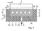
- FIG. 1 shows the structure of a rail according to the invention 16a in connection with the traction means 2.
- the rail 16a according to the invention avoids in the operating condition a direct contact of the traction means 2 on the guide surface 9.
- a lubricant in particular a lubricating oil of the internal combustion engine by means of a pressure circulation lubrication on a center introduced into the rail 6 lubricant channel 13 introduced into the U-shaped receptacle 29. From the lubricant channel 13, the lubricant enters a lubricant groove 14a before the lubricant broadly reaches a pressure gap 15 which extends over the entire width of the traction means 2 and is bounded on both sides by the ribs 17a, 17b.
- a leakage gap 19a, 19b is furthermore provided between the ribs 17a, 17b and the side surfaces 18a, 18b of the pulling means 2.
- the leakage gap width or the gap dimension "s" is chosen so that on the one hand an unhindered faster Lubricant outlet is suppressed from the pressure nip 15 and on the other hand, a friction between the rims 17a, 17b and the side surfaces 18a, 18b of the traction means is omitted.
- the rail 16a is further designed such that a rim height "b" of the ribs 17a, 17b does not exceed a tooth root height "z" of the traction means 2.
- the U-shaped receptacle 29 of the rail 16a in conjunction with the traction means 2 limit in the operating state filled with a lubricant pressure chamber.
- FIG. 2 shows the rail 16b according to the invention in a perspective.
- the guide surface 9 is provided with a central lubricant groove 16b extending over almost the entire length of the rail 16b, from which offset obliquely formed transverse grooves 20 follow.
- the transverse grooves 20 have the task of distributing the pressurized lubricant from the lubricant groove 14 b over a wide area on the guide surface 9 in order to produce a desired pressure gap 15.
- the ribs 17a, 17b are at both ends, that is both at the pivot bearing 8 end facing as well as in an entry zone 21 of the traction means 2 on the rail 16b respectively opposite to each other spread outwards. This measure results in an improved traction means guide and allows a tolerance compensation, if, for example, the rail 16b is not aligned in the operating state, in terms of angle to the course of the traction means 2.
- the rail 16c according to FIG. 3 is provided with a lubricant groove 14 c, the ends of which forms a lubricant collector 22 at the end facing the inlet zone 21.
- the lubricant collector 22 cooperates with an external spray nozzle 23, from which lubricant is injected in a targeted manner into the lubricant collector 22.
- the guide surface 9 according to FIG. 3 is still with one scaly macrostructure 25 provided which causes an improved lubricant adhesion, which has an advantageous effect on the formation of the pressure gap 15.
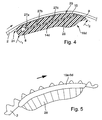
- the rail 16d shown in longitudinal section according to FIG. 4 illustrates in particular the course of the lubricant channels 14d.
- Starting point of the lubricant channels 14d is the pivot bearing 8 of the rail 16d, which is fed to the lubrication lubricant pressure circulation lubrication of the internal combustion engine. From there, the lubricant is further promoted to build the pressure nip 15 in the U-shaped receptacle 29.
- the lubricant channels 14d include a longitudinal bore 26 which, starting from the rotary bearing 8, extends almost over the entire length of the rail 16d and terminates in the guide surface 9 at the end. In order to avoid a sharp-edged transition between the traction means 2 and the rail 16d, this has on both end sides radii "r 1 " and "r 2 ", the smaller are as the associated radii of the traction means 2.
- inventive rail 16a to 16d underlining shows the FIG. 5 a self-adjusting pressure curve 28 of the U-shaped receptacle 29 of the inventive rails 16a to 16d, which adjusts over the length of the end face 11.
- the greatest pressure forms on the inside of the traction means 2, which slowly degrades over the length of the end face 11, without this being completely eliminated and the traction means 2 abuts the guide surface 9.
Abstract
Description
Die vorliegende Erfindung betrifft eine Schiene für einen Zugmitteltrieb, die als Spannschiene oder Führungsschiene ausgebildet, zur Anlage an einem Zugmittel vorgesehen ist. Derartige Spann- oder Führungsschienen werden insbesondere genutzt, um in Zugmitteltrieben eine Kette oder einen Riemen zu spannen. Zur Erzielung einer verbesserten Führung des Zugmittels an der dazu vorgesehenen Kontaktfläche der Schiene ist diese seitlich von Borden begrenzt.The present invention relates to a rail for a traction mechanism, which is designed as a clamping rail or guide rail, is provided for engagement with a traction means. Such clamping or guide rails are used in particular to tension a traction drive chain or a belt. To achieve improved guidance of the traction means on the contact surface of the rail provided for this purpose, this is bounded laterally by Borden.
Schienen der zuvor beschriebenen Bauart finden vielfältige Anwendung, insbesondere in Zugmitteltrieben von Brennkraftmaschinen. Für kraftübertragende bzw. drehmomentübertragende Zugmittel werden derartige Schienen eingesetzt, um stets eine für die Funktion des Zugmitteltriebs ausreichende Vorspannung zu gewährleisten. Derartige Schienen sind üblicherweise an einem ortsfest positionierten Bolzen schwenkbar angeordnet, zur Bildung eines Drehlagers. Versetzt zu dem Drehlager ist der Schiene ein Spannelement zugeordnet, beispielsweise eine Druckfeder oder eine hydraulisch arbeitende Vorrichtung. Die hydraulisch wirkende Vorrichtung umfasst einen Kolben, der von einem hydraulischen Druckfluidmittel beaufschlagt auf die Schiene eine Kraft ausübt, um so die Spannung des Zugmittels zu erhöhen. Gleichzeitig schließt die hydraulische Spannvorrichtung eine als Druckbegrenzung wirkende Einrichtung ein, die ein Überschreiten eines definierten Drucks verhindert.Rails of the type described above find a variety of applications, especially in traction drives of internal combustion engines. For power-transmitting or torque-transmitting traction means such rails are used to always ensure sufficient for the function of the traction mechanism bias. Such rails are usually pivotally mounted on a fixedly positioned pin, to form a pivot bearing. Offset to the pivot bearing of the rail is associated with a clamping element, such as a compression spring or a hydraulically operating device. The hydraulically-acting device comprises a piston, which exerts a force on the rail by means of a hydraulic pressure fluid, in order to increase the tension of the traction device. At the same time, the hydraulic tensioning device includes a device acting as a pressure limiting device, which prevents an exceeding of a defined pressure.
Die
Aus der
Der vorliegenden Erfindung liegt die Aufgabe zugrunde, eine Schiene für einen Zugmitteltrieb zu schaffen, mit der eine verringerte Reibung zwischen dem Zugmittel und der Schiene realisierbar ist.The present invention has for its object to provide a rail for a traction mechanism, with a reduced friction between the traction means and the rail can be realized.
Die Lösung dieser Problemstellung wird durch die Merkmale des Anspruchs 1 gelöst. Danach bildet die erfindungsgemäße Spannschiene bzw. Führungsschiene im Betriebszustand eine von einem Schmiermittel benetzte U-förmige Aufnahme, wodurch das Zugmittel auf einem Schmiermittelfilm weitestgehend kontaktlos zu der Schiene geführt ist. Die Schmiermittelführung erfolgt dabei so, dass sich zwischen dem Zugmittel und der Führungsfläche der Schiene ein von dem Schmiermittel gebildeter Druckspalt einstellt. Zusätzlich ist die Schiene maßlich so an die Breite des Zugmittels angepasst, dass sich jeweils beidseitig zwischen dem Zugmittel und dem Bord der Schiene ein definiertes Spaltmaß in Form eines mit dem Schmiermittel gefüllten Leckspaltes einstellt.The solution of this problem is solved by the features of claim 1. Thereafter, the clamping rail or guide rail according to the invention in the operating state forms a wetted by a lubricant U-shaped receptacle, whereby the traction means is guided on a lubricant film largely contactless to the rail. The lubricant guide is carried out so that adjusts a pressure gap formed by the lubricant between the traction means and the guide surface of the rail. In addition, the rail is dimensionally adapted to the width of the traction means, that set on both sides between the traction means and the board of the rail a defined gap in the form of a filled with the lubricant leakage gap.
Der seitliche Leckspalt zwischen den Borden der Schiene und dem Zugmittel in Verbindung mit einem Druckspalt, der sich zwischen der Führungsfläche und der Innenseite des Zugmittels einstellt, bewirkt die Bildung eines druckkammerähnlichen Gebildes im Bereich der U-förmigen Aufnahme.The lateral leakage gap between the ribs of the rail and the traction means in conjunction with a pressure gap, which is established between the guide surface and the inside of the traction means, causes the formation of a pressure chamber-like structure in the region of the U-shaped receptacle.
Vorteilhaft erstreckt sich die U-förmige Aufnahme und damit die Druckkammer über die gesamte Länge der Schiene, wodurch das Zugmittel hydrodynamisch aufschwimmt, ohne radialen und axialen Kontakt zur der Schiene. Damit stellt sich eine nahezu reibungsfreie Führung des Zugmittels im Bereich der Schiene ein, was sich vorteilhaft auf den Verschleiß einerseits und die Lebensdauer des Zugmittels andererseits auswirkt. Für eine mit einem derartigen reibungsmindernden Zugmitteltrieb ausgerüstete Brennkraftmaschine, stellt sich damit außerdem ein verbesserter Wirkungsgrad ein.Advantageously, the U-shaped receptacle and thus the pressure chamber extends over the entire length of the rail, whereby the traction means hydrodynamically floats, without radial and axial contact with the rail. This results in a virtually frictionless guidance of the traction means in the region of the rail, which has an advantageous effect on the wear on the one hand and the life of the traction means on the other hand. For an equipped with such a friction-reducing traction drive internal combustion engine, thus also sets an improved efficiency.
Weitere vorteilhafte Ausgestaltungen der Erfindung sind Gegenstand der abhängigen Ansprüche 2 bis 18.Further advantageous embodiments of the invention are the subject of the
Gemäß einer bevorzugten Ausgestaltung der Erfindung wird das Schmiermittel in einer von der Führungsfläche der Schiene und dem Zugmittel radial begrenzten Zone der U-förmige Aufnahme zugeführt. Vorteilhaft kann durch den Druck des Schmiermittels unmittelbar Einfluss auf den Druckspalt, d. h. die sich einstellende Druckspalthöhe genommen werden, der unmittelbar die Vorspannung des Zugmittels beeinflusst. Die erfindungsgemäße Führungsschiene, mit der gleichzeitig die Vorspannung des als Riemen gestalteten Zugmittels beeinflussbar ist, benötigt vorteilhaft kein weiteres, separates Spannsystem. Damit stellt sich zusätzlich ein Kostenvorteil der erfindungsgemäßen Schiene ein.According to a preferred embodiment of the invention, the lubricant is supplied in a radially bounded by the guide surface of the rail and the traction means zone of the U-shaped receptacle. Advantageously, by the pressure of the lubricant directly influence the pressure gap, d. H. the adjusting pressure gap height are taken, which directly affects the bias of the traction means. The guide rail according to the invention, with the same time the bias of the traction means designed as a belt can be influenced, advantageously requires no further, separate clamping system. This raises an additional cost advantage of the rail according to the invention.
Eine weitere Ausgestaltung der Erfindung schließt eine strukturierte Führungsfläche der Schiene ein. Die Struktur der Schiene ermöglicht eine gewollte verbesserte Ölanhaftung an der Führungsfläche, verbunden mit einem reduzierten Reibwert zwischen dem Zugmittel und der Schiene.Another embodiment of the invention includes a structured guide surface of the rail. The structure of the rail allows a desired improved oil adhesion to the guide surface, combined with a reduced coefficient of friction between the traction means and the rail.
Weiterhin schließt die Erfindung ein, die Führungsfläche der Schiene mit einer Makrostruktur zu versehen, die ähnlich der Oberfläche von Golfbällen gestaltet ist. Bevorzugt bietet sich dazu eine schuppenartig auf die Führungsfläche aufgebrachte Makrostruktur an, um die Schmiermittelanhaftung zu verbessern, verbunden mit einem verringerten Reibwert zwischen dem Zugmittels und der Schiene.Furthermore, the invention includes providing the guide surface of the rail with a macrostructure designed similar to the surface of golf balls. For this purpose, a macrostructure applied to the guide surface in a scale-like manner preferably serves to improve the lubricant adhesion, combined with a reduced coefficient of friction between the traction means and the rail.
Alternativ oder zusätzlich schließt die Erfindung ein, das Zugmittel bevorzugt innenseitig, d.h. auf der zur Schiene gerichteten Seite mit einer Makrostruktur zu versehen. Über die Makrostruktur des Zugmittels wird stets Schmiermittel in die Kontaktzone zwischen Schiene und Zugmittel gefördert, verbunden mit einer gewünschten Reibwertreduzierung.Alternatively or additionally, the invention includes, the traction means preferably inside, i. provided on the side facing the rail with a macrostructure. Over the macrostructure of the traction means lubricant is always promoted in the contact zone between rail and traction means, combined with a desired Reibwertreduzierung.
Vorzugsweise wird als Schmiermittel für die Schiene und das Zugmittel das Schmieröl der Brennkraftmaschine eingesetzt, welches über die Druckumlaufschmierung zugeleitet werden kann. Dazu bietet es sich an, das Schmiermittel versetzt zur Stirnseite der Schiene, unter Berücksichtigung der Drehrichtung des Zugmittels in die U-förmige Aufnahme einzuleiten.Preferably, the lubricating oil of the internal combustion engine is used as a lubricant for the rail and the traction device, which can be fed via the pressure circulation lubrication. For this purpose, it is advisable to introduce the lubricant offset to the end face of the rail, taking into account the direction of rotation of the traction means in the U-shaped receptacle.
Als Maßnahme um das Schmiermittel gleichmäßig zwischen der Schiene und der Innenseite des als Riemen ausgebildeten Zugmittels einzubringen ist die Führungsfläche der Schiene mit zumindest einer Schmiermittelnut versehen. Dabei erstreckt sich die Schmiermittelnut nahezu über die gesamte Länge der Schiene, wobei jeweils zu den Stirnseiten ein nutfreier Abstand eingehalten wird, damit das unter Druck stehende Schmiermittel nicht drucklos aus dem druckkammerartigen Gebilde entweichen kann.As a measure to introduce the lubricant evenly between the rail and the inside of the traction device designed as a belt, the guide surface of the rail is provided with at least one lubricant groove. In this case, the lubricant groove extends almost over the entire length of the rail, wherein a groove-free distance is maintained in each case to the end faces, so that the pressurized lubricant can not escape pressure from the pressure chamber-like structure.
Alternativ zu einer der Druckumlaufschmierung der Brennkraftmaschine angeschlossenen Schmiermittelzuführung der Schiene, ist die Erfindung weiterhin übertragbar auf Schienen, bei denen die Schmiermittelversorgung über Spritzdüsen erfolgt. Dazu ist die Schiene mit einem sogenannten Schmiermittelsammler versehen, einem breitflächigen Eintritt der Schmiermittelnut , der eine Aufweitung des in die Führungsfläche eingebrachten Schmiermittelnut darstellt. Im Betriebszustand ist die Schmiermitteldüse so ausgerichtet, dass diese gezielt das Schmiermittel in den dafür vorgesehenen Sammer der Schiene einbringt. Im Betriebszustand wird das Schmiermittel von einem Schmiermittelkeil, der sich zwischen der Schiene und dem Zugmittel bildet, kontinuierlich in den sich verengenden Spalt im Bereich der Schiene weitergeleitet, wodurch sich das Zugmittel ebenfalls gegenüber der Schiene hydrodynamisch aufschwimmt.As an alternative to a lubricant feed of the rail connected to the pressure circulation lubrication of the internal combustion engine, the invention is furthermore transferable to rails in which the supply of lubricant is effected by means of spray nozzles. For this purpose, the rail is provided with a so-called lubricant collector, a broad-surface entry of the lubricant groove which represents a widening of the lubricating groove introduced into the guide surface. In the operating state, the lubricant nozzle is aligned so that it specifically introduces the lubricant in the designated chamber of the rail. In the operating state, the lubricant from a lubricant wedge, which forms between the rail and the traction means, continuously forwarded in the narrowing gap in the rail, whereby the traction means also floating hydrodynamically with respect to the rail.
Eine weitere vorteilhafte Ausgestaltung der Erfindung sieht vor, ein oder mehrere Längsrillen, in Verbindung mit Querrillen in die Führungsfläche der Schiene einzubringen, über die das Schmiermittel breitflächig verteilt werden kann. Die Anzahl sowie die Gestaltung der Rillen wird dabei vorzugsweise durch Versuche ermittelt, zur Erzielung eines Optimums zwischen der eingeleiteten Schmiermittelmenge einerseits und dem sich damit ergebenden Druckaufbau zwischen der Schiene und dem Zugmittel andererseits.A further advantageous embodiment of the invention provides to introduce one or more longitudinal grooves, in conjunction with transverse grooves in the guide surface of the rail over which the lubricant can be distributed over a wide area. The number and design of the grooves is preferably determined by experiments, to achieve an optimum between the amount of lubricant introduced on the one hand and the resulting pressure build-up between the rail and the traction means on the other.
Eine wirksame Schmiermittelzuführung kann außerdem über ein Drehlager der Schiene erfolgen, welches einem Schienenende zugeordnet ist, um das die Schiene schwenkbar ist. Von dem Drehlager, welches bevorzugt mit der Druckumlaufschmierung der Brennkraftmaschine in Verbindung steht, gelangt das Schmiermittel beispielsweise über zumindest eine Schmiermittelbohrung bzw. einen Schmiermittelkanal zu der Führungsfläche, der U-förmigen Aufnahme der Schiene. Die Verteilung des Schmiermittels verbessernd, mündet die Schmiermittelbohrung bevorzugt in eine Schmiermittelnut der Führungsfläche.An effective lubricant supply can also take place via a pivot bearing of the rail, which is assigned to a rail end, about which the rail is pivotable. Of the pivot bearing, which is preferably in communication with the pressure circulation lubrication of the internal combustion engine, the lubricant passes, for example via at least one lubricant bore or a lubricant channel to the guide surface, the U-shaped receptacle of the rail. Improving the distribution of the lubricant, the lubricant bore preferably opens into a lubricant groove of the guide surface.
Ein weiteres Gestaltungsmerkmal der Erfindung betrifft die Borde, an denen das Zugmittel seitlich geführt ist. Das erfindungsgemäße vorteilhafte hydrodynamische Aufschwimmen des Zugmittels im Bereich der u-förmig gestalteten Schiene wird unmittelbar von dem Spaltmaß bestimmt, das sich jeweils beidseitig des Zugmittels und den Borden der Schiene einstellt. Über das Spaltmaß, das auch als Leckspalt zu bezeichnen ist, wird im Betriebszustand stets eine Schmiermittelmenge abgeführt, verbunden mit einem Druckabbau. Über die Höhe der Schienenborde sowie die Breite des Spaltmaßes ist dieser Druckabbau beeinflussbar. Vorteilhaft wird die Bordhöhe an eine Zahnflusshöhe des als Riemen ausgebildeten Zugmittels angepasst. Eine solche Bordhöhe vermeidet einen Zugmittelkontakt im Bereich der Profilierung bzw. der Verzahnung mit dem Bord der Schiene, was den Verschleiß und die Reibung verringert.Another design feature of the invention relates to the shelves on which the traction means is guided laterally. The advantageous hydrodynamic floating of the traction device according to the invention in the region of the U-shaped rail is determined directly by the gap dimension, which adjusts in each case on both sides of the traction device and the ribs of the rail. About the gap, which is also referred to as leakage gap, a lubricant quantity is always removed in the operating state, combined with a pressure reduction. About the Height of the rail shelves and the width of the gap, this pressure reduction can be influenced. Advantageously, the board height is adapted to a tooth flow height of the traction means designed as a belt. Such a board height avoids Zugmittelkontakt in the field of profiling or the teeth with the board of the rail, which reduces wear and friction.
Die Erfindung ermöglicht die Verwendung einer einteiligen Schiene, beispielsweise aus Aluminium-Guss preiswert hergestellbare Schienen. Die erfindungsgemäßen Maßnahmen bewirken eine deutlich reduzierte Reibung zwischen den Kontaktpartnern, der Schiene und dem Zugmittel, wodurch eine einteilige, aus einem Werkstoff hergestellte Schiene einsetzbar ist.The invention enables the use of a one-piece rail, for example made of cast aluminum inexpensive producible rails. The inventive measures cause a significantly reduced friction between the contact partners, the rail and the traction means, whereby a one-piece, made of a material rail can be used.
Alternativ dazu ist die Erfindung ebenfalls auf herkömmlich aufgebaute Schienen übertragbar, beispielsweise auf Schienen mit einem aus Aluminium hergestellten Grundkörper, an dem formschlüssig ein Gleitkörper aus Kunststoff befestigt ist. Dazu ist die Führungsfläche des Gleitkörpers mit zumindest einem Schmiermittelkanal oder zumindest einer Schmiermittelnut versehen, entsprechend den zuvor erläuterten Ausgestaltungen und Wirkungen.Alternatively, the invention is also transferable to conventionally constructed rails, for example on rails with a base body made of aluminum, on the form-fitting a sliding body made of plastic is attached. For this purpose, the guide surface of the slider is provided with at least one lubricant channel or at least one lubricant groove, according to the previously explained embodiments and effects.
Die Wirksamkeit der erfindungsgemäßen Schiene erfordert die Einhaltung von durch Versuche empirisch ermittelten Maßen. Als Spaltmaß bzw. als Maß für den Leckspalt, der sich beidseitig des Zugmittels zu den Borden der Schiene ergibt, ist ein Wert "s" von ≤ 0,3 mm vorgesehen. Das Zusammenwirken des Zugmittels in Verbindung mit der erfindungsgemäß gestalteten Schiene ergibt einen Druckspalt "h", der sich zwischen der Führungsfläche der Schiene und dem Zugmittel einstellt und erfindungsgemäß ≥ 0,1 mm beträgt.The effectiveness of the rail according to the invention requires compliance with empirically determined by experiments measurements. As a gap measure or as a measure of the leakage gap, which results on both sides of the traction means to the edges of the rail, a value "s" of ≤ 0.3 mm is provided. The interaction of the traction means in conjunction with the rail designed according to the invention results in a pressure gap "h", which is established between the guide surface of the rail and the traction means and according to the invention is ≥ 0.1 mm.
Weiterhin ist gemäß der Erfindung vorgesehen, die Borde der Schiene jeweils endseitig so auszubilden, dass diese jeweils einen nach außen entgegengesetzt spreizenden Bereich bilden. Diese Maßnahme ermöglicht auch bei einer nicht optimal zu dem Zugmittel ausgerichteten Schiene eine dauerhafte zerstörungsfreie und gleichzeitig reibungsmindernde Führung des Zugmittels in der Schiene. Außerdem ist die Führungsfläche der Schiene an beiden Enden, zumindest jedoch im Einlaufbereich des Zugmittels mit einem zur Zugmittelführung abweichend stärker gerundeten Bereich versehen, der sich ebenfalls reibungsmindernd auswirkt.Furthermore, it is provided according to the invention, the shelves of the rail in each case form the end so that they each form an outwardly oppositely spreading region. This measure also makes it possible, even with a rail that is not optimally aligned with the traction device, to provide permanent, non-destructive and at the same time friction-reducing guidance of the traction device in the rail. In addition, the guide surface of the rail at both ends, at least However, provided in the inlet region of the traction means with a deviating to the Zugmittelführung more rounded area, which also has a friction-reducing effect.
Die Erfindung wird anhand von sechs Zeichnungen näher erläutert. Es zeigen:
- Figur 1
- in einer Schnittansicht den Aufbau der erfindungsgemäßen Schiene in Verbindung mit einem Zugmittel;
Figur 2- in einer Perspektive die erfindungsgemäße Schiene als Einzelteil;
Figur 3- einen Ausschnitt der in
Figur 2 Figur 4- in einem Längsschnitt eine erfindungsgemäße Schiene, die an dem Zugmittel abgestützt ist;
Figur 5- eine Prinzipskizze, die einen Druckaufbau des Schmiermit- tels im Bereich der Schiene innenseitig des Zugmittels dar- stellt;
Figur 6- den Aufbau eines bekannten Zugmitteltriebs in Verbindung einer Schiene, mit der das Zugmittel vorgespannt wird.
- FIG. 1
- in a sectional view of the structure of the rail according to the invention in conjunction with a traction means;
- FIG. 2
- in a perspective rail according to the invention as a single part;
- FIG. 3
- a section of in
FIG. 2 shown on an enlarged scale and with a lubricant collector; - FIG. 4
- in a longitudinal section a rail according to the invention, which is supported on the traction means;
- FIG. 5
- a schematic diagram showing a pressure build-up of the lubricant in the rail on the inside of the traction means;
- FIG. 6
- the structure of a known traction mechanism drive in conjunction with a rail, with which the traction means is biased.
Um die Erfindung näher zu erläutern, wird zunächst auf die
Die
Die
Die Schiene 16c gemäß
Die im Längsschnitt abgebildete Schiene 16d gemäß
Die Wirksamkeit der erfindungsgemäßen Schiene 16a bis 16d unterstreichend zeigt die
- 11
- Zugmitteltriebtraction drive
- 22
- Zugmitteltraction means
- 33
- Antriebsorgandrive member
- 44
- Abtriebsorganoutput element
- 55
- Spannsystemclamping system
- 66
- Schienerail
- 77
- Federmittelspring means
- 88th
- Drehlagerpivot bearing
- 99
- Führungsflächeguide surface
- 1010
- Stößeltappet
- 1111
- Stirnflächeface
- 1212
- Bordshelf
- 1313
- Schmiermittelkanallubricant channel
- 14a14a
- Schmiermittelnutlubricant groove
- 14b14b
- Schmiermittelnutlubricant groove
- 14c14c
- Schmiermittelnutlubricant groove
- 1515
- Druckspaltnip
- 16a16a
- Schienerail
- 16b16b
- Schienerail
- 16c16c
- Schienerail
- 16d16d
- Schienerail
- 17a17a
- Bordshelf
- 17b17b
- Bordshelf
- 18a18a
- Seitenflächeside surface
- 18b18b
- Seitenflächeside surface
- 19a19a
- Leckspaltleakage gap
- 19b19b
- Leckspaltleakage gap
- 2020
- Querrilletransverse groove
- 2121
- Eintrittszoneentry zone
- 2222
- Schmiermittelsammlerlubricant collector
- 2323
- Spritzdüsenozzle
- 2424
- Schmiermitteleintraglubricant entry
- 2525
- Makrostrukturmacrostructure
- 2626
- Längsbohrunglongitudinal bore
- 27a27a
- Stichbohrungbranch bore
- 27b27b
- Stichbohrungbranch bore
- 27c27c
- Stichbohrungbranch bore
- 2828
- Druckverlaufpressure curve
- 2929
- Aufnahmeadmission
Claims (18)
- Rail for a flexible drive (1) which is configured as a tensioning rail or a guide rail for contact on a drawing means (2), such as a chain or belt, a guide face (9) of the rail (6; 16a to 16d) being delimited by lateral rims (12; 17a, 17b), which guide face (9) is intended to guide the drawing means (2) and in the operating state, the drawing means (2) is guided in regions in a contactless manner with respect to the rail (6; 16a to 16d) via a lubricant film in a U-shaped receptacle (29) which is wetted by a lubricant, a pressure gap (15) being formed over the length of the rail (6; 16a to 16d) between the drawing means (2) and the guide face (9), and a leakage gap (19a, 19b) being formed on both sides of the drawing means (2) opposite the rims (12; 17a, 17b), characterized in that a rim height (b) is ≤ a tooth base height (z) of the drawing means (2) which is configured as a belt and the guide face (9) of the rail (6; 16a to 16d) encloses at least one lubricant groove (14a to 14c), which is configured at one end as a lubricant collector (22).
- Rail according to Claim 1, in which the lubricant is fed via a lubricant inlet (24) in a zone of the U-shaped receptacle (29), which zone is delimited radially by the guide face (9) of the rail (16a to 16d) and the drawing means (2).
- Rail according to Claim 1, in which at least one part region of the U-shaped receptacle (29) has a structured surface.
- Rail according to Claim 3, in which the surface of the guide face (9) is configured at least in regions as a macrostructure (25).
- Rail according to Claim 3, in which the surface of the guide face (9) has a macrostructure (25) of overlapping design.
- Rail according to Claim 1, which is assigned to a drawing means (2) which has a macrostructure on one side which interacts with the rail (16a to 16d).
- Rail according to Claim 1, in which the lubricant is introduced into the U-shaped receptacle (29) offset towards one end of the rail (16a to 16d).
- Rail according to Claim 1, the lubricant groove (14a to 14c), which forms a longitudinal groove, of the guide face (9) extending as far as possible over the entire length of the rail (16a to 16d).
- Rail according to Claim 1, the guide face (9) of the rail (16a to 16d) enclosing one or more longitudinal grooves in conjunction with transverse grooves in addition to or as an alternative to the lubricant groove (14a to 14c).
- Rail which is arranged such that it can pivot about a rotational bearing (8) and which interacts with a spring means (7) in a manner which is spaced apart from the rotational bearing (8), according to Claim 1, the lubricant passing via the rotational bearing (8) into at least one lubricant channel (13) and being conducted from there via at least one branch bore (27a to 27c) into the lubricant groove (14a to 14c) and into the U-shaped receptacle (29).
- Rail according to Claim 1, the lubricant being fed via a spray nozzle (23) which is positioned separately from the rail (16a to 16d).
- Rail recording to Claim 1 which comprises two components, a basic carrier which is arranged such that it can pivot over the rotational bearing (8), and a sliding body which interacts with the drawing means (2).
- Rail according to Claim 15, the sliding body of which, which is manufactured from plastic, is fastened to the basic carrier which is manufactured from aluminium, in particular in a form-fitting manner.
- Rail according to Claim 1, having a single-piece construction, aluminium or plastic being provided as material.
- Rail according to Claim 1, in which, in the installed state, a leakage gap (19a, 19b) is formed between the rims (17a, 17b) and the drawing means (2), the value "s" being ≤ 0.3 mm.
- Rail according to Claim 1, in which, in the operating state, a pressure gap (15) is formed between the guide face (9) and the drawing means (2), the pressure gap (15) having a value "h" of ≤ 0.1 mm.
- Rail according to Claim 1, the rims (17a, 17b) being spread outwards in each case in an opposite direction to one another at both ends of the rail (16a to 16d).
- Rail according to Claim 1, the guide face (9) of the rail (16a to 16d) having radii "r1, r2" at both ends, which radii are smaller than associated radii of the drawing means profile.
Applications Claiming Priority (2)
| Application Number | Priority Date | Filing Date | Title |
|---|---|---|---|
| DE102004058948A DE102004058948A1 (en) | 2004-12-08 | 2004-12-08 | Oil guide on clamping and guide rails |
| PCT/EP2005/012024 WO2006061075A1 (en) | 2004-12-08 | 2005-11-10 | Oil supply system for supplying oil to slide rails and guide rails |
Publications (2)
| Publication Number | Publication Date |
|---|---|
| EP1819945A1 EP1819945A1 (en) | 2007-08-22 |
| EP1819945B1 true EP1819945B1 (en) | 2011-01-19 |
Family
ID=35708900
Family Applications (1)
| Application Number | Title | Priority Date | Filing Date |
|---|---|---|---|
| EP05807730A Expired - Fee Related EP1819945B1 (en) | 2004-12-08 | 2005-11-10 | Oil supply system for supplying oil to slide rails and guide rails |
Country Status (6)
| Country | Link |
|---|---|
| US (1) | US7942769B2 (en) |
| EP (1) | EP1819945B1 (en) |
| KR (1) | KR20070087589A (en) |
| CN (1) | CN100510477C (en) |
| DE (2) | DE102004058948A1 (en) |
| WO (1) | WO2006061075A1 (en) |
Families Citing this family (27)
| Publication number | Priority date | Publication date | Assignee | Title |
|---|---|---|---|---|
| DE102006058429A1 (en) * | 2006-12-12 | 2008-06-19 | Schaeffler Kg | Spray nozzle for a chain drive |
| DE102007026939A1 (en) * | 2007-06-12 | 2008-12-24 | Audi Ag | Sliding element for chain drive, is integrally formed, and has sliding surface turned to chain of chain drive, where sliding surface has leading section for leading chain on specific curve |
| JP4386378B2 (en) * | 2007-07-31 | 2009-12-16 | 株式会社椿本チエイン | Tensioner lever |
| JP2009074387A (en) * | 2007-09-19 | 2009-04-09 | Nok Corp | Chain guide and chain drive device |
| KR101906787B1 (en) * | 2011-06-03 | 2018-10-11 | 보르그워너 인코퍼레이티드 | Tensioner and shoe therefor |
| JP2013083292A (en) * | 2011-10-07 | 2013-05-09 | Tsubakimoto Chain Co | Transmission guide |
| DE102012206565A1 (en) | 2012-04-20 | 2013-10-24 | Schaeffler Technologies AG & Co. KG | Inverted-tooth chain for use in automotive industry, has chain side bars coupled by connection pins and comprising pair of teeth and side bar spines arranged opposite to teeth, where spines comprise structure introduced into side bar spines |
| JP5513576B2 (en) * | 2012-09-26 | 2014-06-04 | 富士重工業株式会社 | Chain tensioner lever |
| DE102012220302B4 (en) * | 2012-11-08 | 2021-07-22 | Bayerische Motoren Werke Aktiengesellschaft | Friction-reduced rail for timing chain drive |
| ITTO20130640A1 (en) * | 2013-07-29 | 2015-01-30 | Dayco Europe Srl | TRANSMISSION SYSTEM INCLUDING A WET ORGANIC TOOTHED BELT |
| JP2015137685A (en) * | 2014-01-21 | 2015-07-30 | 株式会社椿本チエイン | guide shoe |
| JP6298350B2 (en) | 2014-04-26 | 2018-03-20 | ボーグワーナー インコーポレーテッド | Oil jet arm, chain span lubrication method using the oil jet arm, chain tensioning device, and chain span lubrication method using the chain tensioning device |
| US20170248205A1 (en) * | 2014-09-05 | 2017-08-31 | Borgwarner Inc. | Improved chain guide and tensioning apparatus |
| GB2531244B (en) * | 2014-09-30 | 2016-09-21 | Martin Frappell Christopher | Tensioning Apparatus |
| DE102014014905A1 (en) | 2014-10-08 | 2016-04-14 | Iwis Motorsysteme Gmbh & Co. Kg | Clamping rail with a lubricant channel |
| DE102015001334A1 (en) * | 2015-02-03 | 2016-08-04 | Iwis Motorsysteme Gmbh & Co. Kg | Articulated chain with friction-reduced chain link back |
| US9631715B1 (en) * | 2015-10-20 | 2017-04-25 | Ford Global Technologies, Llc | One-piece integrated chain snubber and oil diverter for a transaxle |
| DE102016002327A1 (en) | 2016-02-26 | 2017-01-19 | Iwis Motorsysteme Gmbh & Co. Kg | Clamping or guide rail with an oil catching pocket |
| JP6788181B2 (en) * | 2016-08-04 | 2020-11-25 | 株式会社椿本チエイン | Chain transmission device |
| US10309520B2 (en) * | 2017-02-17 | 2019-06-04 | Ford Global Technologies, Llc | Snubber with scoop feature for automotive transmission |
| JP2018145977A (en) * | 2017-03-01 | 2018-09-20 | 株式会社椿本チエイン | Guide shoe |
| CN111350806A (en) * | 2018-12-21 | 2020-06-30 | 舍弗勒技术股份两合公司 | Tensioning device, wrap-around transmission assembly and internal combustion engine |
| DE102020102994A1 (en) * | 2019-03-19 | 2020-09-24 | Schaeffler Technologies AG & Co. KG | Chain drive for an internal combustion engine |
| CN110513170B (en) * | 2019-08-29 | 2021-02-19 | 上海瀚通汽车零部件有限公司 | Timing chain system and engine thereof |
| US11466755B2 (en) | 2020-02-03 | 2022-10-11 | Borgwarner Inc. | Chain guide and tensioning apparatus for vehicles |
| JP2021143685A (en) * | 2020-03-10 | 2021-09-24 | 株式会社椿本チエイン | Chain guide |
| KR20230000058A (en) * | 2021-06-24 | 2023-01-02 | 현대자동차주식회사 | Mechanical chain tensioner |
Family Cites Families (21)
| Publication number | Priority date | Publication date | Assignee | Title |
|---|---|---|---|---|
| DE2525352C3 (en) * | 1975-06-06 | 1978-05-11 | Joh. Winklhofer & Soehne, 8000 Muenchen | Hydraulic chain tensioner |
| DD256350A1 (en) * | 1986-12-29 | 1988-05-04 | Polygraph Leipzig | DEVICE FOR OPERATING TIMING BELTS |
| JP2540899Y2 (en) * | 1991-04-15 | 1997-07-09 | 株式会社椿本チエイン | I-shaped tensioner lever |
| JPH089476Y2 (en) * | 1991-11-07 | 1996-03-21 | 株式会社椿本チエイン | Integrated structure of chain guide arm and shoe |
| JPH07167264A (en) * | 1993-12-16 | 1995-07-04 | Toyota Motor Corp | Chain lubricating device |
| JP3379266B2 (en) * | 1995-03-02 | 2003-02-24 | アイシン精機株式会社 | Auto tensioner |
| DE19609583A1 (en) * | 1995-03-14 | 1996-09-19 | Borg Warner Automotive Kk | Support arm for engine timing chain tensioner |
| BE1009250A3 (en) * | 1995-03-21 | 1997-01-07 | Four Industriel Belge | Method and heating tanks for bath metal melt. |
| JPH08303541A (en) * | 1995-04-28 | 1996-11-19 | Hokushin Ind Inc | Contact body with resin made chain |
| JP2895786B2 (en) * | 1995-11-10 | 1999-05-24 | 株式会社椿本チエイン | Transmission chain tensioner device |
| DE19542861A1 (en) * | 1995-11-17 | 1997-05-28 | Ford Werke Ag | Chain guide and slide rail, in particular for internal combustion engines |
| US5647811A (en) * | 1996-01-18 | 1997-07-15 | Borg-Warner Automotive, Inc. | Chain tensioner with integral arm |
| US5779582A (en) * | 1996-03-06 | 1998-07-14 | Mott; Philip J. | Chain guide with tapered side rails |
| JP3269011B2 (en) * | 1997-07-28 | 2002-03-25 | 株式会社椿本チエイン | Transmission chain running guide shoe |
| JPH11190398A (en) * | 1997-12-26 | 1999-07-13 | Fuji Heavy Ind Ltd | Timing belt |
| JP3460980B2 (en) | 2000-06-07 | 2003-10-27 | 本田技研工業株式会社 | Guide device for winding power transmission member |
| JP2002266957A (en) * | 2001-03-12 | 2002-09-18 | Gates Unitta Asia Co | Belt tension adjusting device and driving transmission system |
| JP2003113913A (en) * | 2001-10-02 | 2003-04-18 | Tsubakimoto Chain Co | Movable lever for transmission chain |
| JP2003214504A (en) * | 2002-01-22 | 2003-07-30 | Tsubakimoto Chain Co | Movable lever for transmission chain |
| DE10230739A1 (en) * | 2002-07-09 | 2004-01-22 | Ina-Schaeffler Kg | Toothed belt drive for driving the camshaft of an internal combustion engine |
| JP3898159B2 (en) * | 2003-06-16 | 2007-03-28 | 本田技研工業株式会社 | Guide device for winding power transmission member |
-
2004
- 2004-12-08 DE DE102004058948A patent/DE102004058948A1/en not_active Withdrawn
-
2005
- 2005-11-10 WO PCT/EP2005/012024 patent/WO2006061075A1/en active Application Filing
- 2005-11-10 EP EP05807730A patent/EP1819945B1/en not_active Expired - Fee Related
- 2005-11-10 CN CNB2005800423734A patent/CN100510477C/en not_active Expired - Fee Related
- 2005-11-10 US US11/721,080 patent/US7942769B2/en not_active Expired - Fee Related
- 2005-11-10 KR KR1020077012768A patent/KR20070087589A/en not_active Application Discontinuation
- 2005-11-10 DE DE502005010892T patent/DE502005010892D1/en active Active
Also Published As
| Publication number | Publication date |
|---|---|
| CN101076680A (en) | 2007-11-21 |
| KR20070087589A (en) | 2007-08-28 |
| WO2006061075A1 (en) | 2006-06-15 |
| CN100510477C (en) | 2009-07-08 |
| US20090325748A1 (en) | 2009-12-31 |
| EP1819945A1 (en) | 2007-08-22 |
| DE102004058948A1 (en) | 2006-06-14 |
| DE502005010892D1 (en) | 2011-03-03 |
| US7942769B2 (en) | 2011-05-17 |
Similar Documents
| Publication | Publication Date | Title |
|---|---|---|
| EP1819945B1 (en) | Oil supply system for supplying oil to slide rails and guide rails | |
| DE60308616T2 (en) | Hydraulic chain tensioner | |
| DE3609233C2 (en) | ||
| DE19923905B4 (en) | Clamping device for chains | |
| DE102016221892B4 (en) | Chain tensioning device | |
| DE102008020744A1 (en) | Assembly unit of a traction mechanism drive | |
| EP1920170A1 (en) | Tensioning system | |
| DE112015001376T5 (en) | Oil spray arm and method of lubricating a chain end using the oil spray arm; and a chain tensioner and method for lubricating a chain center using said chain tensioner | |
| DE102009029297A1 (en) | Piston pump, particularly high-pressure pump for fuel injection device of internal combustion engine, comprises pump piston, which is adjustably guided to shaft in radial manner | |
| DE102014014905A1 (en) | Clamping rail with a lubricant channel | |
| WO2006027153A1 (en) | Housing of a tensioning system with an integrated spray nozzle | |
| DE10336782A1 (en) | jig | |
| DE112009000471B4 (en) | Chain tensioner | |
| DE19943402A1 (en) | Self-tensioner creates measured tension in engine synchronous belt in order to reduce noise and prolong useful life, is of free piston type with body in which piston is moved | |
| DE102016002327A1 (en) | Clamping or guide rail with an oil catching pocket | |
| WO2020187351A1 (en) | Chain drive for an internal combustion engine | |
| EP2593694B1 (en) | Chain drive for internal combustion engines | |
| DE102016224347B4 (en) | Pump, in particular high-pressure pump of a fuel injection system, with a plunger assembly which has a rotation and a Schmierstoffversor- supply of the roller by an extended bearing pin | |
| DE102009058587A1 (en) | Internal combustion engine i.e. internal combustion engine having V-shaped-cylinder-arrangement, for motor vehicle, has casing device closed in cross section and provided in area of load strand of control chain connects sprocket wheels | |
| DE102005031295B4 (en) | Drive device with two belt drives arranged on the front side of an internal combustion engine | |
| DE19942983A1 (en) | Hydraulic tappet clearance compensation device for IC engines has pressure piston with separate head with smooth end face extending outside housing bore | |
| EP1520120B1 (en) | Toothed belt drive element for actuating the camshaft of an internal combustion engine | |
| DE102009000795B4 (en) | clamping element | |
| EP2423536B1 (en) | Hydraulic tensioning device with temporary storage | |
| DE102017106049A1 (en) | Clamp or guide rail with two juxtaposed sliding lining bodies |
Legal Events
| Date | Code | Title | Description |
|---|---|---|---|
| PUAI | Public reference made under article 153(3) epc to a published international application that has entered the european phase |
Free format text: ORIGINAL CODE: 0009012 |
|
| 17P | Request for examination filed |
Effective date: 20070601 |
|
| AK | Designated contracting states |
Kind code of ref document: A1 Designated state(s): DE FR GB IT |
|
| DAX | Request for extension of the european patent (deleted) | ||
| RBV | Designated contracting states (corrected) |
Designated state(s): DE FR GB IT |
|
| 17Q | First examination report despatched |
Effective date: 20091029 |
|
| GRAP | Despatch of communication of intention to grant a patent |
Free format text: ORIGINAL CODE: EPIDOSNIGR1 |
|
| GRAS | Grant fee paid |
Free format text: ORIGINAL CODE: EPIDOSNIGR3 |
|
| RAP1 | Party data changed (applicant data changed or rights of an application transferred) |
Owner name: SCHAEFFLER TECHNOLOGIES GMBH & CO. KG |
|
| GRAA | (expected) grant |
Free format text: ORIGINAL CODE: 0009210 |
|
| AK | Designated contracting states |
Kind code of ref document: B1 Designated state(s): DE FR GB IT |
|
| REG | Reference to a national code |
Ref country code: GB Ref legal event code: FG4D Free format text: NOT ENGLISH |
|
| REF | Corresponds to: |
Ref document number: 502005010892 Country of ref document: DE Date of ref document: 20110303 Kind code of ref document: P |
|
| REG | Reference to a national code |
Ref country code: DE Ref legal event code: R096 Ref document number: 502005010892 Country of ref document: DE Effective date: 20110303 |
|
| PLBE | No opposition filed within time limit |
Free format text: ORIGINAL CODE: 0009261 |
|
| STAA | Information on the status of an ep patent application or granted ep patent |
Free format text: STATUS: NO OPPOSITION FILED WITHIN TIME LIMIT |
|
| 26N | No opposition filed |
Effective date: 20111020 |
|
| PGFP | Annual fee paid to national office [announced via postgrant information from national office to epo] |
Ref country code: FR Payment date: 20111214 Year of fee payment: 7 |
|
| REG | Reference to a national code |
Ref country code: DE Ref legal event code: R097 Ref document number: 502005010892 Country of ref document: DE Effective date: 20111020 |
|
| PGFP | Annual fee paid to national office [announced via postgrant information from national office to epo] |
Ref country code: DE Payment date: 20120131 Year of fee payment: 7 |
|
| GBPC | Gb: european patent ceased through non-payment of renewal fee |
Effective date: 20111110 |
|
| REG | Reference to a national code |
Ref country code: DE Ref legal event code: R081 Ref document number: 502005010892 Country of ref document: DE Owner name: SCHAEFFLER TECHNOLOGIES AG & CO. KG, DE Free format text: FORMER OWNER: SCHAEFFLER TECHNOLOGIES GMBH & CO. KG, 91074 HERZOGENAURACH, DE Effective date: 20120828 |
|
| PG25 | Lapsed in a contracting state [announced via postgrant information from national office to epo] |
Ref country code: GB Free format text: LAPSE BECAUSE OF NON-PAYMENT OF DUE FEES Effective date: 20111110 |
|
| REG | Reference to a national code |
Ref country code: FR Ref legal event code: ST Effective date: 20130731 |
|
| PG25 | Lapsed in a contracting state [announced via postgrant information from national office to epo] |
Ref country code: IT Free format text: LAPSE BECAUSE OF NON-PAYMENT OF DUE FEES Effective date: 20121110 |
|
| REG | Reference to a national code |
Ref country code: DE Ref legal event code: R119 Ref document number: 502005010892 Country of ref document: DE Effective date: 20130601 |
|
| PG25 | Lapsed in a contracting state [announced via postgrant information from national office to epo] |
Ref country code: DE Free format text: LAPSE BECAUSE OF NON-PAYMENT OF DUE FEES Effective date: 20130601 |
|
| PG25 | Lapsed in a contracting state [announced via postgrant information from national office to epo] |
Ref country code: FR Free format text: LAPSE BECAUSE OF NON-PAYMENT OF DUE FEES Effective date: 20121130 |
|
| P01 | Opt-out of the competence of the unified patent court (upc) registered |
Effective date: 20230522 |