EP1520120B1 - Toothed belt drive element for actuating the camshaft of an internal combustion engine - Google Patents
Toothed belt drive element for actuating the camshaft of an internal combustion engine Download PDFInfo
- Publication number
- EP1520120B1 EP1520120B1 EP03762652A EP03762652A EP1520120B1 EP 1520120 B1 EP1520120 B1 EP 1520120B1 EP 03762652 A EP03762652 A EP 03762652A EP 03762652 A EP03762652 A EP 03762652A EP 1520120 B1 EP1520120 B1 EP 1520120B1
- Authority
- EP
- European Patent Office
- Prior art keywords
- toothed belt
- slide rail
- belt
- belt drive
- toothed
- Prior art date
- Legal status (The legal status is an assumption and is not a legal conclusion. Google has not performed a legal analysis and makes no representation as to the accuracy of the status listed.)
- Expired - Lifetime
Links
- 238000002485 combustion reaction Methods 0.000 title claims description 5
- 239000003921 oil Substances 0.000 description 10
- 239000003595 mist Substances 0.000 description 3
- 229920002635 polyurethane Polymers 0.000 description 2
- 239000004814 polyurethane Substances 0.000 description 2
- 230000005540 biological transmission Effects 0.000 description 1
- 230000015572 biosynthetic process Effects 0.000 description 1
- 238000005553 drilling Methods 0.000 description 1
- 229920001971 elastomer Polymers 0.000 description 1
- 239000000314 lubricant Substances 0.000 description 1
- 238000012423 maintenance Methods 0.000 description 1
- 239000006262 metallic foam Substances 0.000 description 1
- 239000010705 motor oil Substances 0.000 description 1
- 239000004033 plastic Substances 0.000 description 1
- 229920003023 plastic Polymers 0.000 description 1
Images
Classifications
-
- F—MECHANICAL ENGINEERING; LIGHTING; HEATING; WEAPONS; BLASTING
- F01—MACHINES OR ENGINES IN GENERAL; ENGINE PLANTS IN GENERAL; STEAM ENGINES
- F01L—CYCLICALLY OPERATING VALVES FOR MACHINES OR ENGINES
- F01L1/00—Valve-gear or valve arrangements, e.g. lift-valve gear
- F01L1/02—Valve drive
- F01L1/024—Belt drive
-
- F—MECHANICAL ENGINEERING; LIGHTING; HEATING; WEAPONS; BLASTING
- F16—ENGINEERING ELEMENTS AND UNITS; GENERAL MEASURES FOR PRODUCING AND MAINTAINING EFFECTIVE FUNCTIONING OF MACHINES OR INSTALLATIONS; THERMAL INSULATION IN GENERAL
- F16H—GEARING
- F16H7/00—Gearings for conveying rotary motion by endless flexible members
- F16H7/18—Means for guiding or supporting belts, ropes, or chains
-
- F—MECHANICAL ENGINEERING; LIGHTING; HEATING; WEAPONS; BLASTING
- F16—ENGINEERING ELEMENTS AND UNITS; GENERAL MEASURES FOR PRODUCING AND MAINTAINING EFFECTIVE FUNCTIONING OF MACHINES OR INSTALLATIONS; THERMAL INSULATION IN GENERAL
- F16H—GEARING
- F16H7/00—Gearings for conveying rotary motion by endless flexible members
- F16H7/08—Means for varying tension of belts, ropes, or chains
- F16H2007/0863—Finally actuated members, e.g. constructional details thereof
- F16H2007/0872—Sliding members
Definitions
- the invention relates to a toothed belt drive for driving the camshaft of an internal combustion engine, comprising a hydraulic tensioning device for a one-sided toothed toothed belt integrated in the motor, wherein the tensioning device comprises a unilaterally pivotally mounted slide rail, which can be clamped by an actuator against the toothed belt, according to the preamble of claim 1 ,
- timing chains or timing belts designed as toothed belts are used to drive the camshafts. While the timing chain in the engine runs integrated in the oil mist, the toothed belt drives of the previously built toothed belt drives run outside the engine and are shielded there by an additional cover. The advantage of a lower-loss power transmission through a toothed belt is thus repealed by the additional components for shielding the belt outside the engine.
- a tensioning rail for chain drives is used in the DE-A-19913288 described in which the clamping rail consists of a hollow profile which is filled with a metal foam.
- the invention has for its object to avoid the disadvantages of the camshaft drives integrated with the engine timing chains and the timing belt drives with outside the engine timing belt and to create a belt drive with particularly low friction between the slide and the timing belt.
- the invention is based on the finding that by running the belt in the oil mist the inherent difficulty of unfavorable sliding behavior between the most rubber existing belt and the slide rail made of plastic is largely compensated, since in any case a thin layer of oil on the belt trains.
- the slide is provided with a hydrodynamic floating of the belt in her causing, associated with an oil supply holes, these holes directly in the contact surface of the slide on the timing belt are arranged.
- the hydrodynamic floating can be further promoted by a defined geometric design of the slide rail surface.
- the toothed belt wheels 1 to 3 are connected to one another by a toothed belt 4 toothed on one side, for example of polyurethane.
- the timing belt 4 runs in the interior of the engine in an oil bath, so that it constantly runs in the resulting during operation of the engine oil mist.
- a hydraulic tensioning device with a slide rail 5, which is rotatably mounted in the region of one end on a stationary axis 6 and by a not shown , in the field of the other End attacking, known per se, actuator with a predetermined pressing force to the toothed belt 4 can be pressed.
- the curved slide 5 is provided with on both sides upstanding, in this area a U-shaped cross-section of the slide resulting guide side cheeks 7, which flank the timing belt 4 laterally so that it can not slide sideways from the slide.
- the slide rail is provided with a plurality of the contact surface 8 of the toothed belt 4 passing through holes 9, which are respectively connected via only schematically indicated in Figure 2 pipes or hoses 10 with an oil supply means that selectively injects oil between the contact surface 8 and the back of the belt, so that the toothed belt 4 floats hydrodynamically on the slide rail 5.
- an oil supply means that selectively injects oil between the contact surface 8 and the back of the belt, so that the toothed belt 4 floats hydrodynamically on the slide rail 5.
Landscapes
- Engineering & Computer Science (AREA)
- General Engineering & Computer Science (AREA)
- Mechanical Engineering (AREA)
- Devices For Conveying Motion By Means Of Endless Flexible Members (AREA)
Description
Die Erfindung betrifft einen Zahnriemenantrieb zum Antrieb der Nockenwelle einer Brennkraftmaschine, mit einer hydraulischen Spannvorrichtung für einen im Motor integrierten einseitig gezähnten Zahnriemen, wobei die Spannvorrichtung eine einseitig schwenkgelagerte Gleitschiene umfasst, die durch ein Stellglied gegen den Zahnriemen verspannbar ist, entsprechend dem Oberbegriff des Anspruchs 1.The invention relates to a toothed belt drive for driving the camshaft of an internal combustion engine, comprising a hydraulic tensioning device for a one-sided toothed toothed belt integrated in the motor, wherein the tensioning device comprises a unilaterally pivotally mounted slide rail, which can be clamped by an actuator against the toothed belt, according to the preamble of
In der Automobilindustrie geht der Trend zunehmend in die Richtung verbrauchsarmer Aggregate. Die Fahrzeuglebensdauer ist stark angestiegen, sodass gleiche Anforderungen auch für alle einzelnen Komponenten gelten. Für den Antrieb der Nockenwellen kommen derzeit entweder Steuerketten oder als Zahnriemen ausgebildete Steuerriemen zum Einsatz. Während die Steuerkette im Motor integriert im Ölnebel läuft, läuft bei den bisher gebauten Zahnriemenantrieben der Zahnriemen außerhalb des Motors und wird dort durch einen zusätzlichen Deckel (Cover) abgeschirmt. Der Vorteil einer verlustärmeren Kraftübertragung durch einen Zahnriemen wird somit durch die zusätzlichen Bauteile zur Abschirmung des Zahnriemens außerhalb des Motors wieder aufgehoben.In the automotive industry, the trend is increasingly in the direction of low-consumption units. The vehicle life has risen sharply, so that the same requirements apply to all individual components. Currently, either timing chains or timing belts designed as toothed belts are used to drive the camshafts. While the timing chain in the engine runs integrated in the oil mist, the toothed belt drives of the previously built toothed belt drives run outside the engine and are shielded there by an additional cover. The advantage of a lower-loss power transmission through a toothed belt is thus repealed by the additional components for shielding the belt outside the engine.
In der Offenlegungsschrift
Aus der gattungsgemäßen
Eine Spannschiene für Kettenantriebe wird in der
In der
Der Erfindung liegt die Aufgabe zugrunde, die genannten Nachteile der Nockenwellenantriebe mit im Motor integrierten Steuerketten und der Zahnriemenantriebe mit außerhalb des Motors angeordneten Zahnriemen zu vermeiden und einen Zahnriemenantrieb mit besonders geringer Reibung zwischen der Gleitschiene und dem Zahnriemen zu schaffen.The invention has for its object to avoid the disadvantages of the camshaft drives integrated with the engine timing chains and the timing belt drives with outside the engine timing belt and to create a belt drive with particularly low friction between the slide and the timing belt.
Zur Lösung dieser Aufgabe ist erfindungsgemäß ein Zahnriemenantrieb mit den Merkmalen des Anspruchs 1 vorgesehen.To solve this problem, a toothed belt drive according to the invention with the features of
Der Erfindung liegt dabei die Erkenntnis zugrunde, dass durch das Laufen des Zahnriemens im Ölnebel die an sich bestehende Schwierigkeit eines ungünstigen Gleitverhaltens zwischen dem meist aus Gummi bestehenden Riemen und der Gleitschiene aus Kunststoff zum großen Teil kompensiert wird, da ja in jedem Fall eine dünne Ölschicht auf dem Riemen sich ausbildet.The invention is based on the finding that by running the belt in the oil mist the inherent difficulty of unfavorable sliding behavior between the most rubber existing belt and the slide rail made of plastic is largely compensated, since in any case a thin layer of oil on the belt trains.
Zur Verkleinerung der Reibung zwischen dem Zahnriemen und der Gleitschiene der hydraulischen Spannvorrichtung ist dabei vorgesehen, dass die Gleitschiene mit, ein hydrodynamisches Aufschwimmen des Zahnriemens in ihr bewirkenden, mit einer Ölzuführeinrichtung verbundenen Bohrungen versehen ist, wobei diese Bohrungen direkt in der Anlagefläche der Gleitschiene am Zahnriemen angeordnet sind.To reduce the friction between the timing belt and the slide rail of the hydraulic tensioning device is provided that the slide is provided with a hydrodynamic floating of the belt in her causing, associated with an oil supply holes, these holes directly in the contact surface of the slide on the timing belt are arranged.
Durch diese erfindungsgemäße Ausgestaltung wird der nach wie vor bestehende relativ hohe Verschleiß am Riemenrücken infolge der vorhandenen Reibung praktisch vollständig beseitigt, da durch entsprechende Einstellung des Öldrucks und der Ölmenge ein echtes hydrodynamisches "Aufschwimmen" des Riemens in der Gleitschiene erreicht werden kann.By this embodiment of the present invention, the still existing relatively high wear on the belt back due to the existing friction is virtually completely eliminated, as can be achieved by appropriate adjustment of the oil pressure and the amount of oil a true hydrodynamic "floating" of the belt in the slide rail.
Dabei kann durch eine definierte geometrische Ausbildung der Gleitschienenoberfläche das hydrodynamische Aufschwimmen noch weiter begünstigt werden.In this case, the hydrodynamic floating can be further promoted by a defined geometric design of the slide rail surface.
Weitere Vorteile und Einzelheiten der Erfindung ergeben sich aus der Beschreibung eines besonders geeigneten Ausführungsbeispiels zusammen mit den Figuren. Dabei zeigen:
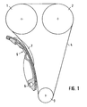
- Fig. 1
- eine schematische Ansicht eines erfindungsgemäßen Zahnriemenantriebs im Motorblock, wobei der Motorblock selbst nicht mit dargestellt ist und
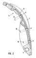
- Fig. 2
- eine vergrößerte Schnittdarstellung der Gleitschiene der hydrodynamischen Spannvorrichtung zum Spannen des Zahnriemens.
- Fig. 1
- a schematic view of a toothed belt drive according to the invention in the engine block, wherein the engine block itself is not shown with and
- Fig. 2
- an enlarged sectional view of the slide rail of the hydrodynamic tensioning device for tensioning the toothed belt.
Bei dem erfindungsgemäßen gesteuerten Antrieb einer Nockenwelle sind die Zahnriemenräder 1 bis 3 durch einen einseitig gezähnten Zahnriemen 4, beispielsweise aus Polyurethan, miteinander verbunden. Der Zahnriemen 4 läuft im Inneren des Motors im Ölbad, sodass er ständig in dem beim Betrieb des Motors entstehenden Ölnebel läuft. Zum Spannen des Zahnriemens 4 - die Einhaltung einer vorgegebenen Spannung ist für die Erzielung einer hohen Lebensdauer von entscheidender Bedeutung - dient erfindungsgemäß eine hydraulische Spannvorrichtung mit einer Gleitschiene 5, die im Bereich des einen Endes auf einer stationären Achse 6 drehgelagert ist und durch ein nicht gezeigtes, im Bereich des anderen Endes angreifendes, an sich bekanntes, Stellglied mit vorgegebener Andrückkraft an den Zahnriemen 4 andrückbar ist. Die gebogene Gleitschiene 5 ist mit beidseitig hochstehenden, in diesem Bereich einen U-förmigen Querschnitt der Gleitschiene ergebenden Führungs-Seitenwangen 7 versehen, die den Zahnriemen 4 seitlich flankieren, sodass er nicht von der Gleitschiene seitlich abgleiten kann.In the controlled drive of a camshaft according to the invention, the
Die Gleitschiene ist mit einer Mehrzahl von die Anlagefläche 8 des Zahnriemens 4 durchsetzenden Bohrungen 9 versehen, die jeweils über nur schematisch in Fig. 2 angedeutete Rohre oder Schläuche 10 mit einer Ölzufuhreinrichtung verbunden sind, die gezielt Öl zwischen die Anlagefläche 8 und den Riemenrücken einpresst, sodass der Zahnriemen 4 hydrodynamisch auf der Gleitschiene 5 aufschwimmt. Dadurch ergibt sich nurmehr eine vernachlässigbare minimale Reibung, sodass nicht nur die daraus resultierenden Reibungsverluste des Zahnriemenantriebs entfallen, sondern insbesondere die Abnutzung des Zahnriemens durch die darauf reibende Gleitschiene wodurch die Lebensdauer eines solchen Zahnriemenantriebs erheblich erhöht werden kann.The slide rail is provided with a plurality of the
- 11
- Zahnriemenradtoothed belt
- 22
- Zahnriemenradtoothed belt
- 33
- Zahnriemenradtoothed belt
- 44
- Zahnriementoothed belt
- 55
- Gleitschieneslide
- 66
- stationäre Achsestationary axis
- 77
- Führungs-SeitenwagenLeadership sidecar
- 88th
- Anlageflächecontact surface
- 99
- Bohrungendrilling
- 1010
- Rohr/SchlauchPipe / tube
Claims (3)
- Toothed belt drive for driving the camshaft of an internal combustion engine, having a hydraulic tensioning device for a toothed belt (4) toothed on one side and incorporated into a motor, wherein the tensioning device comprises a slide rail (5) which is pivotably mounted on one side and which may be braced against the toothed belt (4) by an actuator, the slide rail (5) having a contact face (8), characterised in that the contact face (8) of the slide rail (5) has a plurality of bores (9) spaced apart in the longitudinal direction and connected to an oil supply device, through which bores oil may be injected between the contact face (8) and the back of the toothed belt (4) in order to effect hydrodynamic floating of the toothed belt (4) on the slide rail (5).
- Toothed belt drive according to claim 1, characterised in that the bores (9) are each connected to the oil supply device via tubes or hoses (10).
- Toothed belt drive according to one of the preceding claims, characterised in that the slide rail (5) has guide side cheeks (7) raised on both sides and producing a U-shaped cross-section.
Applications Claiming Priority (3)
| Application Number | Priority Date | Filing Date | Title |
|---|---|---|---|
| DE2002130739 DE10230739A1 (en) | 2002-07-09 | 2002-07-09 | Toothed belt drive for driving the camshaft of an internal combustion engine |
| DE10230739 | 2002-07-09 | ||
| PCT/EP2003/007293 WO2004005758A1 (en) | 2002-07-09 | 2003-07-08 | Toothed belt drive element for actuating the camshaft of an internal combustion engine. |
Publications (2)
| Publication Number | Publication Date |
|---|---|
| EP1520120A1 EP1520120A1 (en) | 2005-04-06 |
| EP1520120B1 true EP1520120B1 (en) | 2008-01-16 |
Family
ID=29761744
Family Applications (1)
| Application Number | Title | Priority Date | Filing Date |
|---|---|---|---|
| EP03762652A Expired - Lifetime EP1520120B1 (en) | 2002-07-09 | 2003-07-08 | Toothed belt drive element for actuating the camshaft of an internal combustion engine |
Country Status (4)
| Country | Link |
|---|---|
| EP (1) | EP1520120B1 (en) |
| AU (1) | AU2003249981A1 (en) |
| DE (2) | DE10230739A1 (en) |
| WO (1) | WO2004005758A1 (en) |
Families Citing this family (2)
| Publication number | Priority date | Publication date | Assignee | Title |
|---|---|---|---|---|
| DE102004058948A1 (en) * | 2004-12-08 | 2006-06-14 | Schaeffler Kg | Oil guide on clamping and guide rails |
| DE602005016469D1 (en) * | 2005-09-27 | 2009-10-15 | Dayco Europe Srl | GEARBOX FOR USE IN OIL AND TIMING BELTS THEREFOR |
Citations (2)
| Publication number | Priority date | Publication date | Assignee | Title |
|---|---|---|---|---|
| DE19812939A1 (en) * | 1997-03-26 | 1999-01-14 | Mitsubishi Motors Corp | Camshaft drive device |
| JP2001187948A (en) * | 1999-12-28 | 2001-07-10 | Unitta Co Ltd | Drive transmitting device |
Family Cites Families (6)
| Publication number | Priority date | Publication date | Assignee | Title |
|---|---|---|---|---|
| DE1650620A1 (en) * | 1967-08-29 | 1970-01-02 | Auto Union Gmbh | Chain tensioning device |
| DE2333688A1 (en) * | 1973-07-03 | 1975-01-23 | Porsche Ag | Tensioning device for belt or chain drive - with vibration damping esp. for I.C. engine camshaft drive |
| DE2445286A1 (en) * | 1974-09-21 | 1976-04-08 | Porsche Ag | Engine camshaft drive tension device - has swinging guide plate, cylinder block mounted bolt controlled |
| JP2540899Y2 (en) * | 1991-04-15 | 1997-07-09 | 株式会社椿本チエイン | I-shaped tensioner lever |
| DE19913288A1 (en) * | 1999-03-24 | 2000-09-28 | Schaeffler Waelzlager Ohg | Chain tensioner for car camshaft drive, comprises hollow profile filled with a metal foam |
| DE10014325B4 (en) * | 2000-03-23 | 2005-02-24 | Joh. Winklhofer & Söhne GmbH und Co KG | Clamp or guide rail for endless drive elements |
-
2002
- 2002-07-09 DE DE2002130739 patent/DE10230739A1/en not_active Withdrawn
-
2003
- 2003-07-08 DE DE50309033T patent/DE50309033D1/en not_active Expired - Lifetime
- 2003-07-08 WO PCT/EP2003/007293 patent/WO2004005758A1/en active IP Right Grant
- 2003-07-08 EP EP03762652A patent/EP1520120B1/en not_active Expired - Lifetime
- 2003-07-08 AU AU2003249981A patent/AU2003249981A1/en not_active Abandoned
Patent Citations (2)
| Publication number | Priority date | Publication date | Assignee | Title |
|---|---|---|---|---|
| DE19812939A1 (en) * | 1997-03-26 | 1999-01-14 | Mitsubishi Motors Corp | Camshaft drive device |
| JP2001187948A (en) * | 1999-12-28 | 2001-07-10 | Unitta Co Ltd | Drive transmitting device |
Non-Patent Citations (1)
| Title |
|---|
| PATENT ABSTRACTS OF JAPAN vol. 2000, no. 24 * |
Also Published As
| Publication number | Publication date |
|---|---|
| AU2003249981A1 (en) | 2004-01-23 |
| WO2004005758A1 (en) | 2004-01-15 |
| DE50309033D1 (en) | 2008-03-06 |
| EP1520120A1 (en) | 2005-04-06 |
| DE10230739A1 (en) | 2004-01-22 |
Similar Documents
| Publication | Publication Date | Title |
|---|---|---|
| EP1819945B1 (en) | Oil supply system for supplying oil to slide rails and guide rails | |
| DE102013110267B4 (en) | KETTENSPANNER LEVER | |
| WO2005121599A1 (en) | Belt assembly with a tensioning device | |
| WO2007014693A1 (en) | Traction mechanism drive | |
| DE102008020161B4 (en) | Clamping device with sliding clamping rail | |
| DE69401335T2 (en) | Track tensioner | |
| DE112015003586T5 (en) | IMPROVED CHAIN GUIDE AND CLAMPING DEVICE | |
| DE60015738T2 (en) | Continuously variable transmission with lubrication nozzles in the output direction to a radial position of maximum power transmission of the belt | |
| EP1520120B1 (en) | Toothed belt drive element for actuating the camshaft of an internal combustion engine | |
| DE3417100C2 (en) | Chain guide for a timing chain to drive a camshaft | |
| WO2008055745A1 (en) | Camshaft drive with geometric cam roller stabilization | |
| DE3609579C2 (en) | ||
| EP0877179A1 (en) | Chain guide | |
| DE102006058429A1 (en) | Spray nozzle for a chain drive | |
| DE4229201C2 (en) | Device for adjusting the camshaft timing | |
| DE102004008683A1 (en) | Traction drive of an internal combustion engine | |
| EP2593694B1 (en) | Chain drive for internal combustion engines | |
| DE102017106049A1 (en) | Clamp or guide rail with two juxtaposed sliding lining bodies | |
| DE10201343A1 (en) | Conveyor system comprises cog belt and toothed pulley, belt having central, unreinforced wedge which fits into pulley groove, and has longitudinal groove at base, into which rib at base of pulley groove fits | |
| DE102004055280B4 (en) | Clamping and guide rail of a camshaft drive chain | |
| DE19855376C1 (en) | Tensioning and damping element for endless chain drives | |
| DE102010024027A1 (en) | Traction mechanism drive has traction mechanism which connects drive wheel with output wheel and clamping rail that is pivotally mounted around clamping rail rotating point | |
| DE102009000795B4 (en) | clamping element | |
| DE10242235A1 (en) | Camshaft with variable valve control for IC engine has an additional cam profile controlled by a servo drive with infinite adjustment | |
| DE102019110885A1 (en) | Chain with lug hole offset |
Legal Events
| Date | Code | Title | Description |
|---|---|---|---|
| PUAI | Public reference made under article 153(3) epc to a published international application that has entered the european phase |
Free format text: ORIGINAL CODE: 0009012 |
|
| 17P | Request for examination filed |
Effective date: 20050103 |
|
| AK | Designated contracting states |
Kind code of ref document: A1 Designated state(s): AT BE BG CH CY CZ DE DK EE ES FI FR GB GR HU IE IT LI LU MC NL PT RO SE SI SK TR |
|
| AX | Request for extension of the european patent |
Extension state: AL LT LV MK |
|
| 17Q | First examination report despatched |
Effective date: 20050413 |
|
| DAX | Request for extension of the european patent (deleted) | ||
| RBV | Designated contracting states (corrected) |
Designated state(s): DE FR IT SE |
|
| RAP1 | Party data changed (applicant data changed or rights of an application transferred) |
Owner name: SCHAEFFLER KG |
|
| GRAP | Despatch of communication of intention to grant a patent |
Free format text: ORIGINAL CODE: EPIDOSNIGR1 |
|
| GRAS | Grant fee paid |
Free format text: ORIGINAL CODE: EPIDOSNIGR3 |
|
| GRAA | (expected) grant |
Free format text: ORIGINAL CODE: 0009210 |
|
| AK | Designated contracting states |
Kind code of ref document: B1 Designated state(s): DE FR IT SE |
|
| REG | Reference to a national code |
Ref country code: SE Ref legal event code: TRGR |
|
| REF | Corresponds to: |
Ref document number: 50309033 Country of ref document: DE Date of ref document: 20080306 Kind code of ref document: P |
|
| ET | Fr: translation filed | ||
| PLBE | No opposition filed within time limit |
Free format text: ORIGINAL CODE: 0009261 |
|
| STAA | Information on the status of an ep patent application or granted ep patent |
Free format text: STATUS: NO OPPOSITION FILED WITHIN TIME LIMIT |
|
| 26N | No opposition filed |
Effective date: 20081017 |
|
| REG | Reference to a national code |
Ref country code: DE Ref legal event code: R082 Ref document number: 50309033 Country of ref document: DE Representative=s name: LINDNER BLAUMEIER PATENT- UND RECHTSANWAELTE, DE |
|
| REG | Reference to a national code |
Ref country code: DE Ref legal event code: R081 Ref document number: 50309033 Country of ref document: DE Owner name: SCHAEFFLER TECHNOLOGIES AG & CO. KG, DE Free format text: FORMER OWNER: CONTITECH ANTRIEBSSYSTEME GMBH, SCHAEFFLER TECHNOLOGIES GMBH &, , DE Effective date: 20120828 Ref country code: DE Ref legal event code: R082 Ref document number: 50309033 Country of ref document: DE Representative=s name: LINDNER BLAUMEIER PATENT- UND RECHTSANWAELTE, DE Effective date: 20120828 Ref country code: DE Ref legal event code: R081 Ref document number: 50309033 Country of ref document: DE Owner name: CONTITECH ANTRIEBSSYSTEME GMBH, DE Free format text: FORMER OWNER: CONTITECH ANTRIEBSSYSTEME GMBH, SCHAEFFLER TECHNOLOGIES GMBH &, , DE Effective date: 20120828 Ref country code: DE Ref legal event code: R081 Ref document number: 50309033 Country of ref document: DE Owner name: SCHAEFFLER TECHNOLOGIES GMBH & CO. KG, DE Free format text: FORMER OWNER: CONTITECH ANTRIEBSSYSTEME GMBH, SCHAEFFLER TECHNOLOGIES GMBH &, , DE Effective date: 20120828 Ref country code: DE Ref legal event code: R082 Ref document number: 50309033 Country of ref document: DE Representative=s name: LINDNER / BLAUMEIER PATENT- UND RECHTSANWAELTE, DE Effective date: 20120828 Ref country code: DE Ref legal event code: R081 Ref document number: 50309033 Country of ref document: DE Owner name: CONTITECH ANTRIEBSSYSTEME GMBH, DE Free format text: FORMER OWNERS: CONTITECH ANTRIEBSSYSTEME GMBH, 30165 HANNOVER, DE; SCHAEFFLER TECHNOLOGIES GMBH & CO. KG, 91074 HERZOGENAURACH, DE Effective date: 20120828 Ref country code: DE Ref legal event code: R081 Ref document number: 50309033 Country of ref document: DE Owner name: SCHAEFFLER TECHNOLOGIES AG & CO. KG, DE Free format text: FORMER OWNERS: CONTITECH ANTRIEBSSYSTEME GMBH, 30165 HANNOVER, DE; SCHAEFFLER TECHNOLOGIES GMBH & CO. KG, 91074 HERZOGENAURACH, DE Effective date: 20120828 |
|
| REG | Reference to a national code |
Ref country code: DE Ref legal event code: R082 Ref document number: 50309033 Country of ref document: DE Representative=s name: LINDNER BLAUMEIER PATENT- UND RECHTSANWAELTE, DE |
|
| REG | Reference to a national code |
Ref country code: DE Ref legal event code: R082 Ref document number: 50309033 Country of ref document: DE Representative=s name: LINDNER BLAUMEIER PATENT- UND RECHTSANWAELTE, DE Effective date: 20140211 Ref country code: DE Ref legal event code: R081 Ref document number: 50309033 Country of ref document: DE Owner name: CONTITECH ANTRIEBSSYSTEME GMBH, DE Free format text: FORMER OWNER: CONTITECH ANTRIEBSSYSTEME GMBH, SCHAEFFLER TECHNOLOGIES AG & CO, , DE Effective date: 20140211 Ref country code: DE Ref legal event code: R081 Ref document number: 50309033 Country of ref document: DE Owner name: SCHAEFFLER TECHNOLOGIES GMBH & CO. KG, DE Free format text: FORMER OWNER: CONTITECH ANTRIEBSSYSTEME GMBH, SCHAEFFLER TECHNOLOGIES AG & CO, , DE Effective date: 20140211 Ref country code: DE Ref legal event code: R082 Ref document number: 50309033 Country of ref document: DE Representative=s name: LINDNER / BLAUMEIER PATENT- UND RECHTSANWAELTE, DE Effective date: 20140211 Ref country code: DE Ref legal event code: R081 Ref document number: 50309033 Country of ref document: DE Owner name: SCHAEFFLER TECHNOLOGIES AG & CO. KG, DE Free format text: FORMER OWNER: CONTITECH ANTRIEBSSYSTEME GMBH, SCHAEFFLER TECHNOLOGIES AG & CO, , DE Effective date: 20140211 Ref country code: DE Ref legal event code: R081 Ref document number: 50309033 Country of ref document: DE Owner name: SCHAEFFLER TECHNOLOGIES AG & CO. KG, DE Free format text: FORMER OWNERS: CONTITECH ANTRIEBSSYSTEME GMBH, 30165 HANNOVER, DE; SCHAEFFLER TECHNOLOGIES AG & CO. KG, 91074 HERZOGENAURACH, DE Effective date: 20140211 Ref country code: DE Ref legal event code: R081 Ref document number: 50309033 Country of ref document: DE Owner name: CONTITECH ANTRIEBSSYSTEME GMBH, DE Free format text: FORMER OWNERS: CONTITECH ANTRIEBSSYSTEME GMBH, 30165 HANNOVER, DE; SCHAEFFLER TECHNOLOGIES AG & CO. KG, 91074 HERZOGENAURACH, DE Effective date: 20140211 |
|
| REG | Reference to a national code |
Ref country code: DE Ref legal event code: R082 Ref document number: 50309033 Country of ref document: DE Representative=s name: LINDNER / BLAUMEIER PATENT- UND RECHTSANWAELTE, DE |
|
| REG | Reference to a national code |
Ref country code: DE Ref legal event code: R082 Ref document number: 50309033 Country of ref document: DE Representative=s name: LINDNER / BLAUMEIER PATENT- UND RECHTSANWAELTE, DE Effective date: 20150323 Ref country code: DE Ref legal event code: R081 Ref document number: 50309033 Country of ref document: DE Owner name: SCHAEFFLER TECHNOLOGIES AG & CO. KG, DE Free format text: FORMER OWNER: CONTITECH ANTRIEBSSYSTEME GMBH, SCHAEFFLER TECHNOLOGIES GMBH &, , DE Effective date: 20150323 Ref country code: DE Ref legal event code: R081 Ref document number: 50309033 Country of ref document: DE Owner name: CONTITECH ANTRIEBSSYSTEME GMBH, DE Free format text: FORMER OWNER: CONTITECH ANTRIEBSSYSTEME GMBH, SCHAEFFLER TECHNOLOGIES GMBH &, , DE Effective date: 20150323 Ref country code: DE Ref legal event code: R081 Ref document number: 50309033 Country of ref document: DE Owner name: SCHAEFFLER TECHNOLOGIES AG & CO. KG, DE Free format text: FORMER OWNERS: CONTITECH ANTRIEBSSYSTEME GMBH, 30165 HANNOVER, DE; SCHAEFFLER TECHNOLOGIES GMBH & CO. KG, 91074 HERZOGENAURACH, DE Effective date: 20150323 Ref country code: DE Ref legal event code: R081 Ref document number: 50309033 Country of ref document: DE Owner name: CONTITECH ANTRIEBSSYSTEME GMBH, DE Free format text: FORMER OWNERS: CONTITECH ANTRIEBSSYSTEME GMBH, 30165 HANNOVER, DE; SCHAEFFLER TECHNOLOGIES GMBH & CO. KG, 91074 HERZOGENAURACH, DE Effective date: 20150323 |
|
| REG | Reference to a national code |
Ref country code: FR Ref legal event code: PLFP Year of fee payment: 14 |
|
| PGFP | Annual fee paid to national office [announced via postgrant information from national office to epo] |
Ref country code: IT Payment date: 20160728 Year of fee payment: 14 |
|
| PGFP | Annual fee paid to national office [announced via postgrant information from national office to epo] |
Ref country code: FR Payment date: 20160727 Year of fee payment: 14 Ref country code: SE Payment date: 20160726 Year of fee payment: 14 |
|
| REG | Reference to a national code |
Ref country code: SE Ref legal event code: EUG |
|
| REG | Reference to a national code |
Ref country code: FR Ref legal event code: ST Effective date: 20180330 |
|
| PG25 | Lapsed in a contracting state [announced via postgrant information from national office to epo] |
Ref country code: SE Free format text: LAPSE BECAUSE OF NON-PAYMENT OF DUE FEES Effective date: 20170709 |
|
| PG25 | Lapsed in a contracting state [announced via postgrant information from national office to epo] |
Ref country code: FR Free format text: LAPSE BECAUSE OF NON-PAYMENT OF DUE FEES Effective date: 20170731 |
|
| PG25 | Lapsed in a contracting state [announced via postgrant information from national office to epo] |
Ref country code: IT Free format text: LAPSE BECAUSE OF NON-PAYMENT OF DUE FEES Effective date: 20170708 |
|
| PGFP | Annual fee paid to national office [announced via postgrant information from national office to epo] |
Ref country code: DE Payment date: 20200731 Year of fee payment: 18 |
|
| REG | Reference to a national code |
Ref country code: DE Ref legal event code: R119 Ref document number: 50309033 Country of ref document: DE |
|
| PG25 | Lapsed in a contracting state [announced via postgrant information from national office to epo] |
Ref country code: DE Free format text: LAPSE BECAUSE OF NON-PAYMENT OF DUE FEES Effective date: 20220201 |