EP1819002B1 - Electrolyte composition for nickel-zinc batteries - Google Patents
Electrolyte composition for nickel-zinc batteries Download PDFInfo
- Publication number
- EP1819002B1 EP1819002B1 EP07250401A EP07250401A EP1819002B1 EP 1819002 B1 EP1819002 B1 EP 1819002B1 EP 07250401 A EP07250401 A EP 07250401A EP 07250401 A EP07250401 A EP 07250401A EP 1819002 B1 EP1819002 B1 EP 1819002B1
- Authority
- EP
- European Patent Office
- Prior art keywords
- electrolyte
- zinc
- cell
- battery cell
- hydroxide
- Prior art date
- Legal status (The legal status is an assumption and is not a legal conclusion. Google has not performed a legal analysis and makes no representation as to the accuracy of the status listed.)
- Active
Links
Images


Classifications
-
- H—ELECTRICITY
- H01—ELECTRIC ELEMENTS
- H01M—PROCESSES OR MEANS, e.g. BATTERIES, FOR THE DIRECT CONVERSION OF CHEMICAL ENERGY INTO ELECTRICAL ENERGY
- H01M10/00—Secondary cells; Manufacture thereof
- H01M10/24—Alkaline accumulators
- H01M10/26—Selection of materials as electrolytes
-
- H—ELECTRICITY
- H01—ELECTRIC ELEMENTS
- H01M—PROCESSES OR MEANS, e.g. BATTERIES, FOR THE DIRECT CONVERSION OF CHEMICAL ENERGY INTO ELECTRICAL ENERGY
- H01M10/00—Secondary cells; Manufacture thereof
- H01M10/04—Construction or manufacture in general
- H01M10/0431—Cells with wound or folded electrodes
-
- H—ELECTRICITY
- H01—ELECTRIC ELEMENTS
- H01M—PROCESSES OR MEANS, e.g. BATTERIES, FOR THE DIRECT CONVERSION OF CHEMICAL ENERGY INTO ELECTRICAL ENERGY
- H01M10/00—Secondary cells; Manufacture thereof
- H01M10/24—Alkaline accumulators
- H01M10/28—Construction or manufacture
- H01M10/286—Cells or batteries with wound or folded electrodes
-
- H—ELECTRICITY
- H01—ELECTRIC ELEMENTS
- H01M—PROCESSES OR MEANS, e.g. BATTERIES, FOR THE DIRECT CONVERSION OF CHEMICAL ENERGY INTO ELECTRICAL ENERGY
- H01M4/00—Electrodes
- H01M4/02—Electrodes composed of, or comprising, active material
- H01M4/24—Electrodes for alkaline accumulators
- H01M4/244—Zinc electrodes
-
- H—ELECTRICITY
- H01—ELECTRIC ELEMENTS
- H01M—PROCESSES OR MEANS, e.g. BATTERIES, FOR THE DIRECT CONVERSION OF CHEMICAL ENERGY INTO ELECTRICAL ENERGY
- H01M4/00—Electrodes
- H01M4/02—Electrodes composed of, or comprising, active material
- H01M4/24—Electrodes for alkaline accumulators
- H01M4/32—Nickel oxide or hydroxide electrodes
-
- H—ELECTRICITY
- H01—ELECTRIC ELEMENTS
- H01M—PROCESSES OR MEANS, e.g. BATTERIES, FOR THE DIRECT CONVERSION OF CHEMICAL ENERGY INTO ELECTRICAL ENERGY
- H01M6/00—Primary cells; Manufacture thereof
- H01M6/04—Cells with aqueous electrolyte
-
- H—ELECTRICITY
- H01—ELECTRIC ELEMENTS
- H01M—PROCESSES OR MEANS, e.g. BATTERIES, FOR THE DIRECT CONVERSION OF CHEMICAL ENERGY INTO ELECTRICAL ENERGY
- H01M6/00—Primary cells; Manufacture thereof
- H01M6/04—Cells with aqueous electrolyte
- H01M6/045—Cells with aqueous electrolyte characterised by aqueous electrolyte
-
- H—ELECTRICITY
- H01—ELECTRIC ELEMENTS
- H01M—PROCESSES OR MEANS, e.g. BATTERIES, FOR THE DIRECT CONVERSION OF CHEMICAL ENERGY INTO ELECTRICAL ENERGY
- H01M10/00—Secondary cells; Manufacture thereof
- H01M10/24—Alkaline accumulators
- H01M10/30—Nickel accumulators
-
- H—ELECTRICITY
- H01—ELECTRIC ELEMENTS
- H01M—PROCESSES OR MEANS, e.g. BATTERIES, FOR THE DIRECT CONVERSION OF CHEMICAL ENERGY INTO ELECTRICAL ENERGY
- H01M2300/00—Electrolytes
- H01M2300/0002—Aqueous electrolytes
- H01M2300/0014—Alkaline electrolytes
-
- Y—GENERAL TAGGING OF NEW TECHNOLOGICAL DEVELOPMENTS; GENERAL TAGGING OF CROSS-SECTIONAL TECHNOLOGIES SPANNING OVER SEVERAL SECTIONS OF THE IPC; TECHNICAL SUBJECTS COVERED BY FORMER USPC CROSS-REFERENCE ART COLLECTIONS [XRACs] AND DIGESTS
- Y02—TECHNOLOGIES OR APPLICATIONS FOR MITIGATION OR ADAPTATION AGAINST CLIMATE CHANGE
- Y02E—REDUCTION OF GREENHOUSE GAS [GHG] EMISSIONS, RELATED TO ENERGY GENERATION, TRANSMISSION OR DISTRIBUTION
- Y02E60/00—Enabling technologies; Technologies with a potential or indirect contribution to GHG emissions mitigation
- Y02E60/10—Energy storage using batteries
-
- Y—GENERAL TAGGING OF NEW TECHNOLOGICAL DEVELOPMENTS; GENERAL TAGGING OF CROSS-SECTIONAL TECHNOLOGIES SPANNING OVER SEVERAL SECTIONS OF THE IPC; TECHNICAL SUBJECTS COVERED BY FORMER USPC CROSS-REFERENCE ART COLLECTIONS [XRACs] AND DIGESTS
- Y02—TECHNOLOGIES OR APPLICATIONS FOR MITIGATION OR ADAPTATION AGAINST CLIMATE CHANGE
- Y02P—CLIMATE CHANGE MITIGATION TECHNOLOGIES IN THE PRODUCTION OR PROCESSING OF GOODS
- Y02P70/00—Climate change mitigation technologies in the production process for final industrial or consumer products
- Y02P70/50—Manufacturing or production processes characterised by the final manufactured product
-
- Y—GENERAL TAGGING OF NEW TECHNOLOGICAL DEVELOPMENTS; GENERAL TAGGING OF CROSS-SECTIONAL TECHNOLOGIES SPANNING OVER SEVERAL SECTIONS OF THE IPC; TECHNICAL SUBJECTS COVERED BY FORMER USPC CROSS-REFERENCE ART COLLECTIONS [XRACs] AND DIGESTS
- Y10—TECHNICAL SUBJECTS COVERED BY FORMER USPC
- Y10T—TECHNICAL SUBJECTS COVERED BY FORMER US CLASSIFICATION
- Y10T29/00—Metal working
- Y10T29/49—Method of mechanical manufacture
- Y10T29/49002—Electrical device making
- Y10T29/49108—Electric battery cell making
Definitions
- the present invention relates to the rechargeable batteries and more - particularly to electrolyte and electrode compositions for nickel-zinc rechargeable batteries.
- NiCd nickel cadmium
- NiZn Nickel-zinc
- NiZn Rechargeable nickel-zinc
- nickel-zinc battery technology has not been widely deployed in part because it has been found to have a relatively limited cycle life.
- a given nickel-zinc cell can fully charge and discharge for only a fraction of the cycles typically attained with a comparable nickel cadmium cell.
- This is due, at least in part, to zinc redistribution and dendrite formation.
- the problem is most pronounced in nickel-zinc cells used in power tools and other devices requiring rapid discharge.
- Various advances in electrolyte composition have reduced these issues to an extent, but cycle life remains an important consideration. There is a need therefore for electrolytes that provide long cycle life in nickel-zinc cells. There is a further need for electrolytes that are capable of providing high discharge rate and good performance at low temperatures.
- the present invention provides improved nickel-zinc cells having electrolytes suitable for high rate and other demanding applications.
- Aspects of the invention pertain to cells having phosphate buffer electrolyte.
- Such cells may be characterized by the following features: (a) a negative electrode comprising zinc or a zinc compound; (b) a positive electrode comprising nickel oxide, hydroxide, and/or oxyhydroxide; and (c) an electrolyte comprising: (i) between 0.025 and 0.25 M phosphate (ii) between about 0.01 and 1 M fluoride; and (iii) between 4 and 9 M free alkalinity.
- the electrolyte contains not more than 1M borate (e.g., not more than about 0.1M borate).
- the electrolyte compositions recited herein may exist at various stages during fabrication and use of the cell; e.g., prior to formation of the cell.
- the phosphate concentration is between 0.05 and 0.15 M (e.g., between about 0.07 and .11M).
- the electrolyte comprises between 4 and 6M free alkalinity.
- the electrolyte comprises between 6 and 9M free alkalinity.
- the free alkalinity in the electrolyte may be provided as one or more hydroxides such as sodium, lithium, and/or potassium.
- the electrolyte may include a compound that can minimize zinc corrosion. Examples include polyethylene glycol, tetrabutylammonium hydroxide, and an alkyl phosphate ester.
- the electrolyte includes an indium compound such as indium sulfate. The indium compound may be present in the electrolyte in a concentration of between about 0.0003 and 0.01M.
- the nickel-zinc battery cell has a relatively small quantity of electrolyte in comparison to the amount of electrode material.
- Such cell may operate in a "starved" format and have a relatively high concentration of free alkalinity.
- the electrodes positive and/or negative may be fabricated with little if any easily oxidizable organic compound.
- Figure 1A is a graph showing how zinc solubility changes in response to varying alkalinity in an electrolyte.
- Figure 1B is a graph showing how zinc solubility changes in response to varying borate concentration in an electrolyte.
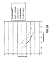
- Figure 2A is a graph showing low-temperature resistivity of phosphate and borate-containing electrolytes.
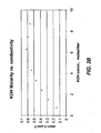
- Figure 2B is a graph showing conductivity versus free KOH concentration in KOH solutions.
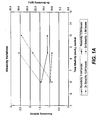
- Figure 3 is a graph showing results of a 1 volt constant voltage discharge for a phosphate buffer electrolyte and a borate buffer electrolyte in sub-C sized nickel-zinc cells at room temperature.
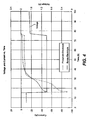
- Figure 4 is a graph showing results of a 1 volt constant voltage discharge for a phosphate buffer electrolyte and a borate buffer electrolyte in sub-C sized nickel-zinc cells at -26°C.
- Figure 5A shows comparative cycle life and capacity results for phosphate and borate electrolyte cells when cycled at 10 Amp constant current discharge coupled to periodic 20 Amp constant current discharges every 50 th cycle.
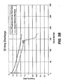
- Figure 5B shows comparative cycle life and capacity results for phosphate and borate electrolyte cells when cycled at 30 Amps constant current discharge.
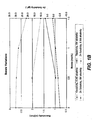
- Figure 6A shows low temperature capacity of borate and phosphate buffered cells at - 10°C
- Figure 6B shows low temperature capacity of borate and phosphate buffered cells at -18°C
- Figure 7 is a graph of carbonate concentration in an alkaline electrolyte of this invention over the course of multiple cycles in a sub-C cell.
- Figure 8a shows an exploded view of a battery cell according to one embodiment of the present invention.
- Figure 8b is a cross-sectional view of the battery cell shown in Figure 8a .
- the present invention provides electrodes and electrolytes for use in nickel-zinc secondary battery cells.
- the electrolyte possesses a composition that limits dendrite formation and other forms of material redistribution in the zinc electrode.
- the electrolytes of the present invention possess one or more of the following characteristics: good performance at low temperatures, long cycle life, low impedance, high power density, and suitability for high rate applications.
- the Eisenberg patent describes alkaline galvanic cells having an electrolyte composition including (1) an alkali or alkaline earth hydroxide present in an amount to produce a stoichiometric excess of hydroxide to acid in the range of 2.5 to 11.0 equivalents per liter, (2) a soluble alkali or earth alkali fluoride in an amount corresponding to a concentration range of 0.01 to 1.0 equivalents per liter of total solution, (3) a borate, arsenate, and/or phosphate salt (e.g., potassium borate, potassium metaborate, sodium borate, and/or sodium metaborate). Specific compositions having these bounds are described as examples in the Eisenberg patent.
- the electrolytes of the present invention provide at least the benefits of the electrolytes disclosed in the Eisenberg patent, while providing improved performance; in particular one or more the following performance characteristics of the battery: high rate discharge, low impedance, high power density, long cycle life, low material redistribution, and good performance at low-temperatures.
- the nickel-zinc cells of this invention employ a starved electrolyte format.
- Such cells have relatively low quantities electrolyte in relation to the amount of active electrode material. They can be easily distinguished from flooded cells, which have free liquid electrolyte in interior regions of the cell.
- a starved cell may be employed to produce a relatively lightweight cell that facilitates recombination of hydrogen and oxygen produced during cycling. Further details of certain starved cell formats are described elsewhere herein.
- the composition of a cell's electrolyte typically varies over the life of the cell.
- the electrolyte compositions of this invention are applicable to any stage of a cell's life, from introduction of the electrolyte to the cell during fabrication, to formation of the cell, to cycling during normal usage. Further, during normal operation, the electrolyte composition may change over the course of a cell cycle from a fully charged cell state to a fully discharged cell state.
- the electrolyte compositions described herein are not associated with any particular state of charge or other cell condition. Unless otherwise indicated, the compositions described herein may be present in a cell at any time over the course of a cell cycle.
- a high alkalinity phosphate buffered electrolyte is one class of electrolyte that was found to have significantly improved power density and low temperature capacity over multiple cycles in comparison to related buffered alkaline electrolyte formulations for nickel-zinc cells.
- the electrolyte employs primarily phosphate as a buffering agent, with little or no borate or other buffering agent.
- the electrolytes also have a relatively high concentration of free alkalinity, typically primarily in the form of hydroxide ion.
- the free alkalinity is provided at a level of at least about 4M, in other embodiments at least about 6M, and in still other embodiments at least about 7M.
- the free alkalinity is provided at a level of between about 4 and 6M. In other embodiments, the free alkalinity is provided at a level of between about 6 and 9M.
- phosphate buffered electrolytes provide improved performance. Because phosphate buffers at pH 12 while borate buffers at pH 13.7, phosphate buffered electrolytes would be expected to experience wider pH swings during operation. However, it has also been found that zinc phosphate is relatively insoluble, and therefore the likelihood of zinc redistribution may be reduced.
- phosphate buffered electrolyte may be included in the phosphate buffered electrolyte to improve performance.
- anions such as silicate may be added.
- certain corrosion inhibiting components may be added.
- An example of such component is tetrabutylammonium hydroxide.
- Another example is indium sulfate.
- the phosphate buffered electrolytes described here generally have a relatively high level of free alkalinity.
- the free alkalinity of an electrolyte includes all alkalinity remaining in the electrolyte after the basic components of the electrolyte have neutralized any acidic components.
- an electrolyte produced by combining 8 moles of potassium hydroxide and 4 moles of dibasic sodium borate (Na 2 HBO 3 ) to produce one liter of a borate buffered electrolyte would have 4M free alkalinity, assuming no other acid or basic species were added to the electrolyte.
- Free alkalinity is typically represented as available hydroxide ions in solution. However, over time and at certain stages in the charge/discharge cycle, some of the hydroxide in the free alkalinity may become unavailable due reaction with carbon dioxide to form carbonates, combination with soluble zinc oxide to form zincate anion, etc. In some cells, carbonate may represent a significant percentage of the free alkalinity; e.g., up to about 20% in some cases.
- Electrolytes having high levels of free alkalinity may be particularly valuable in nickel-zinc cells employing a starved format. Because such cells do not have a reservoir of available electrolyte, the small amount of available electrolyte may profit from relatively high quantities of hydroxide.
- a phosphate buffer of this invention includes the following components.
- some carbonate may be added in concentrations of between about 0.1 and 1M. Highly soluble carbonates such as sodium or potassium carbonate may be used for this purpose.
- certain additives may be used in place of or in addition to tetrabutylammonium hydroxide to reduce zinc corrosion. Examples of such additives include polyethylene glycol or an alkyl phosphate ester such as RA 600 (available from Rohm and Haas Co.). Still further, one or more additives may be provided to reduce the solubility of zinc in the electrolyte.
- Such additives include, for example, silicate, gallate, formaldehyde-sulfoxylate, oxalate, oleate, stearate, sulfide, carbonate, and combinations thereof. These may be provided as soluble salts such as those of sodium or potassium.
- Zinc solubility generally decreases with decreasing alkalinity and increasing borate concentration, while being less affected by presence of phosphate. Zinc solubility is roughly linear with respect to alkalinity (three points were considered for varying hydroxide at 1.5M borate). See Figure 1A . With respect to borate variation, zinc solubility was found to be relatively flat at low borate concentrations (0-1M), while starting to drop much more steeply after 1M borate (see the curve at 8.5M total OH). See Figure 1B .
- Conductance was measured indirectly by measuring the resistance of electrolyte in a thin plastic tube via an apparatus consisting of two electrolyte reservoirs connected by the plastic tubing.
- resistance was found to increase with increasing borate concentration (at least in the range of 0-1.5M), and decrease with increasing alkalinity.
- Increasing phosphate from 0 to 0.1M also seems to increase the resistance somewhat. Note that for alkalinity, the increase in resistance was found to be somewhat curved - flattening out somewhat at alkalinities higher than about 9M, while for borate the relation was somewhat linear in the range studied.
- FIG. 2A is a graph showing the relationship between conductivity and concentration of free KOH (in aqueous solution without other additives).
- Cycling performance was found to roughly track the impedance, with the electrolyte of lowest impedance, also showing the best cycling performance.
- Temperature Increase and Amperage - Figure 3 is a graph showing results of a 1 volt constant voltage discharge for a phosphate buffer electrolyte and a borate buffer electrolyte in sub-C sized nickel-zinc cells at room temperature. These were constructed as jellyroll cells having a capacity of approximately 2 Amp-hours, an impedance of approximately 4 milli-ohms, an open circuit voltage of approximately 1.74 volts, and a loaded voltage of approximately 1.6 volts.
- the borate buffered cell had an electrolyte composition as follows:
- the phosphate buffered cell had an electrolyte composition as follows:
- Figure 3 shows results for two representative cells, one with the borate electrolyte and one with the phosphate electrolyte. Specifically, the figure shows applied voltage and current (Amperes) as a function of time.
- the discharge current of the phosphate buffer cell went from 150 Amps to 60 Amps at room temperature. But for a duration of 20 seconds (an appropriate duration for power tool applications), the average current was about 125 A. For a one volt discharge in a cell weighing about 48 grams this represents an average power density of approximately 2500 W/kg over 20 seconds, which is significantly higher than what one would observe with many other systems including borate buffered cells. It is also noteworthy that the temperature of the phosphate buffer cell reached only 70°C after 1 minute. Under high rate discharge conditions external temperatures of a sub-C cell should not exceed 85°C if there is to be no danger of internal damage to temperature sensitive components such as the separator.
- Figure 4 shows results for a similar experiment conducted at -26°C.
- the two cells shown in this plot were sub-C cells having borate and phosphate buffered electrolyte of the compositions set forth above for Figure 3 .
- the phosphate buffered electrolyte significantly outperformed the borate buffered electrolyte.
- Cycle Life - Figure 5A shows results for a cycle life study in which cells were discharged at 10 Amps constant current, cycle-by-cycle, and on every 50 th cycle they discharged at 20 Amp constant current (and then waiting 24 hours before resuming cycling). From the data presented in Figure 5A , it can be seen that the tested phosphate buffer cell has reached 200 cycles at significantly higher capacity than the borate buffer cell. The capacity separation is even greater as the 300 cycle mark is approached.
- Low temperature testing At a low temperature (about -10°C), sub-C test cells are discharged at a constant current of 12 Amps until fully discharged, reaching approximately 0.3 volts. Based on the number of coulombs passed, one can determine cell capacity.
- the results as depicted in Figure 6A show that phosphate buffered cells (alkaline electrolyte with 0.1M phosphate as described above) have a low temperature capacity of about 0.38 Amp-hours.
- typical borate buffer cells as described above 1.5M borate
- cells employing the phosphate electrolyte delivered approximately 0.38Ah at -10°C when discharged at 12A (curves shown in Figure 6A ).
- the borate electrolyte delivered only 0.22Ah under the same conditions.
- the increase in cell temperature during discharge is also shown in Figure 6A .
- Comparable results for a discharge at -18°C were observed as shown in Figure 6B .
- Impedance - Cells made with the high alkalinity, phosphate buffer electrolyte have about 10-20% lower impedance than cells employing the lower alkalinity borate buffered electrolyte when tested at room temperature. At lower temperatures, particularly below -20C this impedance difference will be greater owing to the increased viscosity of the borate electrolyte. In solution, the phosphate electrolyte was found to be 20% more conductive than the borate electrolyte.
- Cobalt Redistribution - Cobalt is often provided as an additive to the positive nickel electrode. It improves the electrode conductivity and provides other benefits. However, it is important that cobalt remains with the positive electrode and does not redistribute throughout the cell. If cobalt reaches the zinc negative electrode, it may effectively catalyze hydrogen gas generation by lowering the overpotential for hydrogen evolution. Redistribution of cobalt from the positive electrode to the negative electrode during cell formation and cycling is a significant problem. It has been found that use of phosphate buffered electrolytes significantly reduces the amount of cobalt migrating from the positive nickel electrode to the negative zinc electrode in comparison to use of more conventional borate buffered electrolytes.
- the zinc electrode contained only 53.4 ppm cobalt after formation.
- the zinc electrode contained 153.2 ppm cobalt in the zinc electrode of one cell and 155.3 ppm cobalt in the zinc electrode of another cell after formation. It is believed that the phosphate electrolyte reduces the solubility of cobalt compounds and therefore reduces the propensity for cobalt to move from the positive electrode to the negative electrode during formation as well as normal cycling.
- the electrolyte compositions of this invention provide performance advantages when used in high-rate (discharge) applications such as battery cells in power tools.
- the ability to repeatedly discharge at high rates - over the full course of discharge - is an intrinsically desirable feature.
- Cells said to have "high discharge” rates may discharge at rates of at least about 0.01 Amperes per cm 2 of zinc electrode surface area (e.g., average discharge rates of about 0.01 to 0.4 Amperes/cm 2 ). These should be contrasted with cells employed in "low rate” applications, which typically require discharging at an average rate of about 0.001 to 0.01 Amperes/cm 2 .
- Examples of low rate discharge applications include some consumer electronics applications and load leveling for power companies.
- a 1.5 Amp-hour nickel-zinc cell discharges at a rate of at least about 10 Amps, e.g., between about 10 and 60 Amps.
- C discharge rate
- the "C" value of a battery cell represents a discharge rate at which the rated capacity of the cell is fully discharged in one hour. Obviously, this measure depends on the rated capacity of the cell. For sub-C cell format nickel-zinc batteries having a rated capacity of 2Ah, a high rate application might discharge the cell at 20A or 10C.
- a given discharge of a cell may employ multiple high rate events, some of greater magnitude than others.
- Batteries may be designed for maximum discharge rate; e.g., about 20 Amps for a sub-C cell that might correspond to operation of a circular saw. However, such battery might then be placed in a drill or reciprocating saw, which discharges at a lower rate; e.g., about 10 Amps and then placed in a circular saw and discharged at 20 Amps. All this may take place over the course of a single discharge cycle from a fully charged to a fully discharged state.
- high discharge rates and applications are described herein this does not necessarily imply that a high discharge rate be maintained over the full course of discharge. Further, for some applications, it may be appropriate that the cell be able to maintain a high rate discharge for only a short periods or pulses during a discharge and then allowed to recover before the next high rate discharge event.
- a parameter related to discharge rate is power density.
- Power in a cell is measured as the product of voltage and current.
- Power density is a cell's power output per unit weight. Jellyroll type nickel-zinc cells employing certain high alkalinity electrolytes described herein have been found to achieve an average power density of at least about 2500 Watts/Kg over 20 seconds of high rate discharge.
- Various cell design features affect power density and the ability to discharge at high rates. For example, low internal impedance facilitates discharging cells at high rates. A significant fraction of a cell's impedance arises in the electrolyte and electrodes. Thus electrolytes having high ionic conductivity are desirable. Maintaining free hydroxide level at or near an optimum conductivity range in the electrolyte may be important for high rate discharge applications. Reduction in free hydroxide affects conductivity and cell capacity, and can therefore negatively impact the ability to discharge at a high rate.
- Maintaining a desirable free hydroxide level in the electrolyte may be particularly difficult when a cell is discharging or charging at a high rate because at the higher temperatures associated with high rate processes, the organic materials in the electrodes are more susceptible to oxidation, which produces carbon dioxide.
- the carbon dioxide can react with free hydroxide to produce carbonate, effectively removing the free hydroxide from the electrolyte.
- a battery cell's cycle life is the number of charge/discharge cycles available from the cell performing under specified conditions. Cycle life is typically measured by determining how many cycles a cell maintain a particular discharge capacity under specified discharge conditions. Generally speaking, cells with long cycle lives are desirable because they need not be replaced as often as cells having shorter cycle lives. According to various embodiments, nickel-zinc cells employing electrolytes of this invention may have a cycle life of at least about 200 cycles. In further embodiments, the cells have a cycle life of at least about 500 cycles. A cycle is often defined for a particular application. Certain criteria such as depth of discharge (in terms of, e.g., coulombs passed or cell voltage), discharge rate, charging rate and conditions, etc. can define a cycle. Obviously, high rate discharge conditions, deep discharges, fast charging regimes, etc. can negatively impact cycle life. As indicated above, cells employing high alkalinity electrolytes of this invention can maintain long cycle lives even when subjected to high rate discharge rates.
- a cell cycle involves discharging the cell to a depth of 100% of the rated capacity (about 1.8-1.9 A-hours for a sub-C cell) and at a rate of 12A (for a sub-C cell).
- the recharge for power tool applications is typically achieved in under about 1.5 hours.
- the rated capacity of a cell depends on the cells size and construction.
- cycle life is impacted by cell impedance, which is impacted by free hydroxide level in the electrolyte.
- cell impedance which is impacted by free hydroxide level in the electrolyte.
- cells employing the electrolytes described herein perform remarkably well at low-temperature.
- Low temperature performance is important for a number of applications where batteries are to be used in winter and/or in far northerly or southerly latitudes. It is not uncommon for power tools, for example, to be used at temperatures at or below 0°C.
- nickel-zinc cells having "good" low temperature performance maintain at least about 65% of their room temperature capacity at 0°C. In other embodiments, cells maintain at least about 65% of their room temperature capacity at -20°C.
- Certain electrolytes of this invention may be particularly suitable for high rate discharge at low temperatures.
- the cells are capable of discharges of at least about 0.08 Amperes per cm 2 of zinc electrode surface area at 0°C, and more preferably at -20°C.
- low impedance sub-C cells have an overall AC impedance (measured at 1kHz) of below about 5 milliohms, more preferably below about 4.5 milliohms, and most preferably below about 4 milliohms.
- the electrolyte and separator typically contribute a little more than about 50% of the overall impedance of the cell. Impedance due to the electrolyte depends on the conductivity of the electrolyte, which in turn depends on the amount of free hydroxide in the electrolyte. Although an electrolyte's conductivity depends on features in addition to the concentration of potassium hydroxide, it is interesting to see that Figure 2B shows that there is an optimum amount of free hydroxide to obtain maximum conductivity in a simple solution. As with other performance criteria maintaining hydroxide level is important for low impedance.
- the electrolyte compositions and cells of the present invention may provide improved performance by (a) maintaining the free hydroxide level within an optimum range over a prolonged time, (b) reducing zinc corrosion and solubility in the electrolyte and/or (c) employing an optimized buffering range (e.g., borate/phosphate ratio) in the electrolyte.
- an optimized buffering range e.g., borate/phosphate ratio
- the free hydroxide level within particular concentration bounds provides a high conductivity (low impedance) electrolyte over the life of a nickel-zinc battery cell. Further, the free hydroxide level indirectly provides tor long cycle life and the ability to discharge at high rates. It has been observed that in some instances decreasing cell performance correlates with decreasing hydroxide concentration.
- One potential cause for drop-off in free hydroxide is the oxidation of organic compounds to produce carbon dioxide.
- the carbon dioxide is believed to react with hydroxide to form carbonate and thereby reduce the concentration of free hydroxide in the electrolyte.
- the oxidation of certain organic materials, such as those used in wet processing of the electrodes, is believed to be a source of carbon dioxide that contributes to the reduction of hydroxide concentration.
- steps are taken to minimize the amount of carbon dioxide and/or oxidizable organic compounds in the cell.
- the presence of carbon dioxide is reduced by limiting the amount of oxidizable organic compounds in the electrodes. This may be accomplished limited by, e.g., dry processing of one or more of the electrodes and/or replacing easily oxidizable organic compounds with other materials.
- the electrodes provided to an assembled cell contain no more than about 0.5 % by weight of readily oxidizable organic materials.
- Dry processing of the nickel electrode is described in US Provisional Patent Application No. 60/657,825, filed March 1, 2005 , titled “Method of Manufacturing Nickel Zinc Batteries," which is hereby incorporated by reference. Dry fabrication processes need not employ CMC or other flow control agents, and also need not employ certain other organics commonly used in wet fabrication processes. Dry processing of the zinc electrode is also discussed in US Patent Application No. 60/657,825 . In certain embodiments, organic sources of carbon dioxide in the cell electrodes are eliminated or greatly reduced by employing dry processing at least the nickel electrode.
- the zinc electrode or at least the zinc oxide used to manufacture the zinc electrode may be heated prior to electrode manufacture.
- This "burn-out" procedure also described in US Patent Application No. 10/921,062 , may drive out dispersion agents and other organic materials, and carbonate from electrode materials. This effectively eliminates or at least reduces a potentially problematic source of carbon dioxide.
- Baking procedures vary according to the composition and quantity of electrode materials to be treated. In accordance with certain embodiments of the invention, a fabricated electrode or an electrode component is baked at temperatures ranging from about 150°C-320°C for a period of between about 0.5 and 2 hours.
- the negative impact of carbon dioxide and oxidizable organic materials is reduced by replacing easily oxidizable organic materials used in processing with materials that are not as susceptible to oxidation.
- compounds such as polyacrylic acids, polyacrylates, polyolefins (including fluorinated polyolefins such as PTFE), and the like are used in place of cellulosic compounds as binding agents, dispersants, flow agents, etc. during wet processing of one or more of the electrodes.
- a starved cell is generally understood to be one in which the total void volume within the cell electrode stack is not fully occupied by electrolyte.
- a "flooded" cell has all void volume occupied by electrolyte and excess unentrained electrolyte within the cell container.
- the void volume of a starved cell after electrolyte fill may be less than about 10% of the total void volume before fill.
- the electrolyte contains little if any carbonate in the cell.
- carbonate in the electrolyte may serve to reduce the ionic transport capability of the electrolyte.
- carbonate may enter the electrolyte through the oxidation of organic materials or may be present in materials used in electrode manufacturing. Many commercial sources of zinc oxide have significant carbonate content.
- the zinc oxide used to manufacture negative electrodes contains not greater than about 1 percent by weight of carbonate.
- the electrolyte, as provided before filling the cell contains no more than about 1% carbonate.
- the initial amount of hydroxide in the cell is boosted to account for electrolyte that will be taken out of solution during normal operation.
- the initial concentration of hydroxide is set at or slightly above the high concentration end of that window.
- the concentration of hydroxide initially present in the electrolyte may be at least about 7M. In experiments to determine typical carbonate levels existing during the cycling of the cells it has been found that after the initial charge as much as 0.39M may be present. This may increase to 0.7M and above as the cell has cycled more than 150 times.
- Figure 7 shows how carbonate increased in concentration in a sub-C cell employing 8.6M hydroxide and 1.5M borate in the electrolyte and cycled at approximately 20°C. As shown, the concentration of carbonate increased from slightly over 7% of the total alkalinity immediately after formation to approximately 14% of total alkalinity after about 200 cycles.
- zinc is oxidized from metallic zinc to zinc (II) and dissolves in the electrolyte in the form of zincate anions (e.g. Zn(OH) 4 2- ). Shape change and dendrite formation that occur when the dissolved zinc does not replate uniformly on the electrode significantly affects cycle life.
- the electrolyte may contain one or more of the following additives to reduce solubility of zinc in the electrolyte: formaldehyde-sulfoxyate, oxalate, oleate, phosphate, silicate, stearate, sulfide and carbonate anions.
- the electrolyte contains indium in a concentration range of between about 0.0003 and 0.01 moles per liter of total solution.
- the electrolyte formulations may provide improved cycle life and capacity by tuning the ratio of borate to phosphate in the electrolyte.
- the borates, arsenates, and/or phosphates in the electrolyte are trivalent anions that act as buffers. It is believed that the buffering effect beneficially affects the positive electrode (which prefers a highly alkaline environment) and the negative electrode (which prefers a less-alkaline environment). While the Eisenberg patent, referred to above, describes using a borate, phosphate, or arsenate salt alone or in combination in the electrolyte, it has been found that certain concentrations or ratios of borate and phosphate provide particularly good performance. Examples of electrolytes with various amounts of phosphate and/or borate are described elsewhere herein.
- the electrolytes of the invention are typically prepared by adding the phosphate and the other components of the electrolyte to a hydroxide solution in the desired amounts.
- the solution may then be heated, e.g. to 50-60°C, to aid in dissolution of the components. Heat may shorten preparation time, especially if components with low solubilities, such as indium, are added.
- indium may be introduced by alternative methods such as anodic dissolution.
- a standard formula for 2.63 liters of a high alkalinity phosphate buffered electrolyte is as follows: Deionized water, reagent grade 967 grams 33.05% Potassium Hydroxide sol. (45% KOH) 2196 grams 59.01% Sodium Hydroxide (NaOH) 88.5 grams 2.38% Lithium Hydroxide (LiOH) 25.2 grams 0.677% Potassium Fluoride (KF) 45.3 gram 1.22% Zinc Oxide (ZnO) 4.8 grams 0.129% Sodium Phosphate (Na 3 PO 4 .12H 2 O) 127.05 grams 3.41% (0.1M PO 4 -) Indium Sulfate In 2 (SO 4 ) 3 4.29 grams 0.115% (500 ppm In)
- FIGs 8A and 8B are graphical representations of the main components of a cylindrical power cell according to one embodiment of the present invention, with Figure 8A showing an exploded view of the cell. Electrode and electrolyte layers are in cylindrical assembly 801 (also called a "jellyroll"). Negative collector disk 803 and positive collector disk 805 are attached to opposite ends of cylindrical assembly 801. The negative and positive collector disks function as internal terminals, with the negative collector disk electrically connected to the negative electrode and the positive collector disk electrically connected to the positive electrode. Cap 809 and can 813 are external terminals. Negative collector disk 803 includes tab 807 to connect the negative collector disk 803 to cap 809. Positive collector disk 805 is electrically connected to can 813.
- the negative and positive collector disks 803 and 805 are shown with perforations, which may be employed to facilitate bonding to the jellyroll and/or passage of electrolyte from one portion of a cell to another.
- the disks may employ slots (radial or peripheral), grooves, or other structures to facilitate bonding and/or electrolyte distribution.
- the embodiment shown in Figures 8A and 8B has a polarity reverse of that in a conventional NiCd cell, in that the cap is negative and the can positive.
- Gasket 811 rests on bead 815 and electrically insulates cap 809 from can 813.
- the invention may be practiced in a wide range of nickel-zinc cell sizes and formats.
- electrolytes of this invention may be employed in relatively small prismatic cell formats, as well as various larger format cells employed for various non-portable applications.
Landscapes
- Chemical & Material Sciences (AREA)
- Chemical Kinetics & Catalysis (AREA)
- Electrochemistry (AREA)
- General Chemical & Material Sciences (AREA)
- Engineering & Computer Science (AREA)
- Manufacturing & Machinery (AREA)
- Battery Electrode And Active Subsutance (AREA)
- Secondary Cells (AREA)
- Primary Cells (AREA)
Applications Claiming Priority (1)
| Application Number | Priority Date | Filing Date | Title |
|---|---|---|---|
| US11/346,861 US7550230B2 (en) | 2001-03-15 | 2006-02-01 | Electrolyte composition for nickel-zinc batteries |
Publications (3)
| Publication Number | Publication Date |
|---|---|
| EP1819002A2 EP1819002A2 (en) | 2007-08-15 |
| EP1819002A3 EP1819002A3 (en) | 2007-08-22 |
| EP1819002B1 true EP1819002B1 (en) | 2009-07-29 |
Family
ID=37877264
Family Applications (1)
| Application Number | Title | Priority Date | Filing Date |
|---|---|---|---|
| EP07250401A Active EP1819002B1 (en) | 2006-02-01 | 2007-01-31 | Electrolyte composition for nickel-zinc batteries |
Country Status (7)
| Country | Link |
|---|---|
| US (2) | US7550230B2 (enExample) |
| EP (1) | EP1819002B1 (enExample) |
| JP (1) | JP5149511B2 (enExample) |
| CN (1) | CN101034762B (enExample) |
| AT (1) | ATE438205T1 (enExample) |
| CA (1) | CA2576078A1 (enExample) |
| DE (1) | DE602007001701D1 (enExample) |
Cited By (1)
| Publication number | Priority date | Publication date | Assignee | Title |
|---|---|---|---|---|
| US8703330B2 (en) | 2005-04-26 | 2014-04-22 | Powergenix Systems, Inc. | Nickel zinc battery design |
Families Citing this family (59)
| Publication number | Priority date | Publication date | Assignee | Title |
|---|---|---|---|---|
| US7550230B2 (en) * | 2001-03-15 | 2009-06-23 | Powergenix Systems, Inc. | Electrolyte composition for nickel-zinc batteries |
| US7833663B2 (en) | 2003-08-18 | 2010-11-16 | Powergenix Systems, Inc. | Method of manufacturing nickel zinc batteries |
| US20080163478A1 (en) * | 2003-08-18 | 2008-07-10 | Powergenix Systems, Inc. | Method for manufacturing nickel zinc batteries |
| US8048566B2 (en) * | 2008-02-07 | 2011-11-01 | Powergenix Systems, Inc. | Nickel hydroxide electrode for rechargeable batteries |
| JP5599384B2 (ja) * | 2008-04-02 | 2014-10-01 | パワージェニックス システムズ, インコーポレーテッド | 陰性缶を有する円筒形ニッケル─亜鉛セル |
| US20100062347A1 (en) * | 2008-09-09 | 2010-03-11 | Lin-Feng Li | Rechargeable zinc cell with longitudinally-folded separator |
| US8501351B2 (en) | 2009-05-18 | 2013-08-06 | Powergenix Systems, Inc. | Pasted zinc electrode for rechargeable nickel-zinc batteries |
| KR101822666B1 (ko) | 2009-08-07 | 2018-03-08 | 파워지닉스 시스템즈, 인코포레이티드 | 탄소 섬유 아연 음극 |
| JP5922019B2 (ja) | 2009-09-08 | 2016-05-24 | パワージェニックス・システムズ・インコーポレーテッドPowergenix Systems, Incorporated | ニッケル−亜鉛セル用の熱密封セパレータの密封方法、及び、ジェリイロール電極集合体 |
| CN102576827B (zh) * | 2009-10-13 | 2016-09-07 | 鲍尔热尼系统公司 | 具有正盖体的柱形镍-锌电池 |
| US10451897B2 (en) | 2011-03-18 | 2019-10-22 | Johnson & Johnson Vision Care, Inc. | Components with multiple energization elements for biomedical devices |
| EP2750225A4 (en) | 2011-08-23 | 2015-07-29 | Nippon Catalytic Chem Ind | NEGATIVE ELECTRODE MIXTURE OR GEL ELECTROLYTE AND BATTERY WITH THIS NEGATIVE ELECTRODE MIXTURE OR THIS GEL ELECTROLYTE |
| US8857983B2 (en) | 2012-01-26 | 2014-10-14 | Johnson & Johnson Vision Care, Inc. | Ophthalmic lens assembly having an integrated antenna structure |
| CN102832419A (zh) * | 2012-08-30 | 2012-12-19 | 上海锦众信息科技有限公司 | 一种碱性锌电池电解液的制备方法 |
| US9337683B2 (en) | 2012-12-20 | 2016-05-10 | Powergenix Systems, Inc. | Controlling battery states of charge in systems having separate power sources |
| WO2014098875A1 (en) | 2012-12-20 | 2014-06-26 | Powergenix Systems, Inc. | Controlling battery states of charge in systems having separate power sources |
| WO2014110164A1 (en) | 2013-01-14 | 2014-07-17 | Powergenix Systems, Inc. | Pasted nickel hydroxide electrode and additives for rechargeable alkaline batteries |
| US10804573B2 (en) * | 2013-02-06 | 2020-10-13 | Encell Technology, Inc. | Electrolyte for battery containing an iron electrode |
| US10868338B2 (en) * | 2013-02-06 | 2020-12-15 | Encell Technology, Inc. | Nickel-iron battery with high power |
| US10847843B2 (en) | 2013-02-06 | 2020-11-24 | Encell Technology, Inc. | Electrolyte for a nickel-iron battery |
| WO2014124110A1 (en) * | 2013-02-06 | 2014-08-14 | Encell Technology, Inc. | Improved electrolyte for battery containing an iron electrode |
| US10854926B2 (en) * | 2013-02-06 | 2020-12-01 | Encell Technology, Inc. | Nickel-iron battery with high cycle life |
| JP6150383B2 (ja) * | 2013-03-28 | 2017-06-21 | 日産自動車株式会社 | アルカリ電池用電解質及びアルカリ電池 |
| US10333176B2 (en) * | 2013-08-12 | 2019-06-25 | The University Of Akron | Polymer electrolyte membranes for rechargeable batteries |
| WO2015026977A1 (en) * | 2013-08-20 | 2015-02-26 | Encell Technology, Inc. | Manganese and iron electrode cell |
| US20150162570A1 (en) * | 2013-12-10 | 2015-06-11 | Encell Technology, Inc. | Beveled cell design for an alkaline battery to remove gas |
| US20150162571A1 (en) * | 2013-12-10 | 2015-06-11 | Encell Technology, Inc. | Concave cell design for an alkaline battery with a comb spacer |
| US20150162572A1 (en) * | 2013-12-10 | 2015-06-11 | Encell Technology, Inc. | Cell design for an alkaline battery to remove gas |
| JP6296542B2 (ja) * | 2014-03-28 | 2018-03-20 | 日産自動車株式会社 | 亜鉛二次電池用電解質及び亜鉛二次電池 |
| US9715130B2 (en) | 2014-08-21 | 2017-07-25 | Johnson & Johnson Vision Care, Inc. | Methods and apparatus to form separators for biocompatible energization elements for biomedical devices |
| US9599842B2 (en) | 2014-08-21 | 2017-03-21 | Johnson & Johnson Vision Care, Inc. | Device and methods for sealing and encapsulation for biocompatible energization elements |
| US10361405B2 (en) | 2014-08-21 | 2019-07-23 | Johnson & Johnson Vision Care, Inc. | Biomedical energization elements with polymer electrolytes |
| US20160056508A1 (en) * | 2014-08-21 | 2016-02-25 | Johnson & Johnson Vision Care, Inc. | Electrolyte formulations for use in biocompatible energization elements |
| US10381687B2 (en) | 2014-08-21 | 2019-08-13 | Johnson & Johnson Vision Care, Inc. | Methods of forming biocompatible rechargable energization elements for biomedical devices |
| US10627651B2 (en) | 2014-08-21 | 2020-04-21 | Johnson & Johnson Vision Care, Inc. | Methods and apparatus to form biocompatible energization primary elements for biomedical devices with electroless sealing layers |
| US10361404B2 (en) | 2014-08-21 | 2019-07-23 | Johnson & Johnson Vision Care, Inc. | Anodes for use in biocompatible energization elements |
| US9793536B2 (en) | 2014-08-21 | 2017-10-17 | Johnson & Johnson Vision Care, Inc. | Pellet form cathode for use in a biocompatible battery |
| US9383593B2 (en) | 2014-08-21 | 2016-07-05 | Johnson & Johnson Vision Care, Inc. | Methods to form biocompatible energization elements for biomedical devices comprising laminates and placed separators |
| US9941547B2 (en) | 2014-08-21 | 2018-04-10 | Johnson & Johnson Vision Care, Inc. | Biomedical energization elements with polymer electrolytes and cavity structures |
| TW201628233A (zh) * | 2014-10-06 | 2016-08-01 | 艾歐斯能源儲存有限責任公司 | 用於雙極性電化學電池或電池組之終端組件 |
| CN105304946B (zh) * | 2015-09-21 | 2017-11-28 | 新乡市超力新能源有限公司 | 一种可充电锌镍电池用电解液、锌镍电池及其制备方法 |
| US10345620B2 (en) | 2016-02-18 | 2019-07-09 | Johnson & Johnson Vision Care, Inc. | Methods and apparatus to form biocompatible energization elements incorporating fuel cells for biomedical devices |
| US10892524B2 (en) | 2016-03-29 | 2021-01-12 | Eos Energy Storage, Llc | Electrolyte for rechargeable electrochemical cell |
| CN106848407A (zh) * | 2017-02-27 | 2017-06-13 | 安徽桑瑞斯环保新材料有限公司 | 一种用于可再充电碱性电化学电池的碱性电池电解质 |
| US11316203B2 (en) | 2017-05-29 | 2022-04-26 | Namics Corporation | Secondary battery and device including secondary battery |
| CN107634266B (zh) * | 2017-08-18 | 2019-12-10 | 上海交通大学 | 一种锌二次电池用阻燃性电解液 |
| CN109818086A (zh) * | 2017-11-22 | 2019-05-28 | 王明煜 | 一种锌镍电池用碱性胶体电解质及其制备方法、应用 |
| EP3742531B1 (en) * | 2018-01-18 | 2024-02-28 | Maxell, Ltd. | Alkaline secondary battery and charging method of said alkaline secondary battery |
| JP7149079B2 (ja) * | 2018-03-01 | 2022-10-06 | マクセル株式会社 | アルカリ二次電池 |
| US11228058B2 (en) | 2018-04-27 | 2022-01-18 | Kyocera Corporation | Flow battery, flow battery system, and control method |
| CN110718719B (zh) * | 2018-07-13 | 2020-10-30 | 常熟理工学院 | 一种可充电的锌离子电池 |
| FR3099851B1 (fr) | 2019-08-09 | 2021-07-16 | Sunergy | générateurs ELECTROCHIMIQUES secondaires ALCALINS À anode de zinc |
| CN111048846A (zh) * | 2019-12-18 | 2020-04-21 | 陈发生 | 一种镍锌电池 |
| CN111463500B (zh) * | 2020-03-18 | 2021-06-22 | 山东合泰新能源有限公司 | 一种用于锌阳极碱性二次电池的电解液的制备方法 |
| CN111463499B (zh) * | 2020-03-18 | 2021-12-28 | 山东合泰新能源有限公司 | 二次锌镍电池用电解液 |
| CN112164832B (zh) * | 2020-03-19 | 2021-12-28 | 山东合泰新能源有限公司 | 一种电解液的配制方法及其应用的锌镍电池 |
| JP2021158028A (ja) * | 2020-03-27 | 2021-10-07 | 日本碍子株式会社 | 亜鉛二次電池 |
| US11628991B2 (en) * | 2020-08-07 | 2023-04-18 | Illinois Tool Works Inc. | Pressure relief assemblies and methods |
| KR20240001242A (ko) * | 2021-04-29 | 2024-01-03 | 폼 에너지 인코퍼레이티드 | 철 애노드 전기화학 시스템용 전해질 제제 및 첨가제 |
Family Cites Families (41)
| Publication number | Priority date | Publication date | Assignee | Title |
|---|---|---|---|---|
| US3287164A (en) | 1965-01-27 | 1966-11-22 | Douglas Aircraft Co Inc | Electrode and battery |
| US3287166A (en) | 1965-01-27 | 1966-11-22 | Douglas Aircraft Co Inc | Battery electrode and battery, and process for preparing said electrode |
| US3558356A (en) | 1967-02-28 | 1971-01-26 | Texas Instruments Inc | Nickel-zinc battery system which is negative limited during charging thereof |
| US3870564A (en) | 1973-03-30 | 1975-03-11 | Tokyo Shibaura Electric Co | Alkaline cell |
| JPS5461B2 (enExample) | 1973-11-21 | 1979-01-05 | ||
| CS167146B1 (enExample) | 1974-05-21 | 1976-04-29 | ||
| JPS5626108B2 (enExample) | 1975-01-20 | 1981-06-16 | ||
| JPS5629345A (en) | 1979-08-18 | 1981-03-24 | Mitsubishi Electric Corp | Division of wafer |
| US4304828A (en) | 1980-06-27 | 1981-12-08 | Energy Research Corporation | Zinc electrode |
| US4273841A (en) | 1980-08-14 | 1981-06-16 | General Electric Company | Ternary electrolyte for secondary electrochemical cells |
| JPS58163171A (ja) | 1982-03-19 | 1983-09-27 | Sanyo Electric Co Ltd | アルカリ亜鉛蓄電池 |
| JPS59186255A (ja) * | 1983-04-08 | 1984-10-23 | Matsushita Electric Ind Co Ltd | アルカリ一次電池 |
| JPS6056368A (ja) | 1983-09-05 | 1985-04-01 | Sanyo Electric Co Ltd | アルカリ亜鉛蓄電池 |
| JPS60167264A (ja) | 1984-02-10 | 1985-08-30 | Sanyo Electric Co Ltd | アルカリ亜鉛蓄電池 |
| JPS61210192A (ja) | 1985-03-13 | 1986-09-18 | Toshiba Corp | 金属の腐食抑制剤 |
| JPS6235453A (ja) | 1985-08-06 | 1987-02-16 | Sanyo Electric Co Ltd | アルカリ亜鉛蓄電池 |
| US5168018A (en) | 1990-05-17 | 1992-12-01 | Matsushita Electric Industrial Co., Ltd. | Method of manufacturing zinc-alkaline batteries |
| US5215836A (en) | 1991-07-18 | 1993-06-01 | Electrochimica Corporation | Alkaline galvanic cells |
| JP3553104B2 (ja) * | 1992-08-04 | 2004-08-11 | 株式会社エスアイアイ・マイクロパーツ | アルカリ電池 |
| JP2918446B2 (ja) | 1994-04-27 | 1999-07-12 | 富士電気化学株式会社 | 電池の負極亜鉛缶 |
| US5556720A (en) | 1994-08-18 | 1996-09-17 | Energy Research Corporation | Sealed zinc secondary battery and zinc electrode therefor |
| JPH08185856A (ja) * | 1994-12-28 | 1996-07-16 | Sanyo Electric Co Ltd | 電池用希土類−ニッケル系水素吸蔵合金の表面改質処理法 |
| JP3370486B2 (ja) | 1995-07-21 | 2003-01-27 | 松下電器産業株式会社 | アルカリ電池 |
| US6261720B1 (en) | 1996-09-20 | 2001-07-17 | Matsushita Electric Industrial Co., Ltd. | Positive electrode active material for alkaline storage batteries |
| US7033700B2 (en) | 2000-11-10 | 2006-04-25 | Powergenix Systems, Inc. | Formulation of zinc negative electrode for rechargeable cells having an alkaline electrolyte |
| CA2325308A1 (en) | 2000-11-10 | 2002-05-10 | Jeffrey Phillips | Negative electrode formulation for a low toxicity zinc electrode having additives with redox potentials negative to zinc potential |
| US7829221B2 (en) | 2000-11-10 | 2010-11-09 | Powergenix Systems, Inc. | Cobalt containing positive electrode formulation for a nickel-zinc cell |
| CA2325791A1 (en) | 2000-11-10 | 2002-05-10 | Jeffrey Phillips | Negative electrode formulation for a low toxicity zinc electrode having additives with redox potentials positive to zinc potential |
| CA2325595A1 (en) | 2000-11-10 | 2002-05-10 | Jeffrey Phillips | Charger for a rechargeable nickel-zinc battery |
| CA2325640A1 (en) | 2000-11-10 | 2002-05-10 | Jeffrey Phillips | Positive and negative interactive electrode formulation for a zinc-containing cell having an alkaline elelctrolyte |
| US6790559B2 (en) * | 2001-03-15 | 2004-09-14 | Powergenix Systems, Inc. | Alkaline cells having positive nickel hydroxide electrodes with fluoride salt additives |
| US6818350B2 (en) | 2001-03-15 | 2004-11-16 | Powergenix Systems, Inc. | Alkaline cells having low toxicity rechargeable zinc electrodes |
| US7550230B2 (en) | 2001-03-15 | 2009-06-23 | Powergenix Systems, Inc. | Electrolyte composition for nickel-zinc batteries |
| US7008723B2 (en) * | 2001-08-21 | 2006-03-07 | Ecosol Solar Technologies Inc. | Method of manufacture of an anode composition for use in a rechargeable electrochemical cell |
| US7049030B2 (en) | 2003-03-06 | 2006-05-23 | The Gillette Company | Battery |
| CN1283022C (zh) | 2003-03-10 | 2006-11-01 | 华南理工大学 | 锌镍二次电池及其制备方法 |
| CN2632866Y (zh) | 2003-07-17 | 2004-08-11 | 比亚迪股份有限公司 | 锌镍电池 |
| US7833663B2 (en) | 2003-08-18 | 2010-11-16 | Powergenix Systems, Inc. | Method of manufacturing nickel zinc batteries |
| US20050153203A1 (en) * | 2004-01-13 | 2005-07-14 | Stauffer John E. | Lead-zinc battery |
| US7785740B2 (en) * | 2004-04-09 | 2010-08-31 | Air Products And Chemicals, Inc. | Overcharge protection for electrochemical cells |
| US8703330B2 (en) | 2005-04-26 | 2014-04-22 | Powergenix Systems, Inc. | Nickel zinc battery design |
-
2006
- 2006-02-01 US US11/346,861 patent/US7550230B2/en not_active Expired - Lifetime
-
2007
- 2007-01-29 CA CA002576078A patent/CA2576078A1/en not_active Abandoned
- 2007-01-31 AT AT07250401T patent/ATE438205T1/de not_active IP Right Cessation
- 2007-01-31 DE DE602007001701T patent/DE602007001701D1/de active Active
- 2007-01-31 JP JP2007020646A patent/JP5149511B2/ja active Active
- 2007-01-31 CN CN2007100923030A patent/CN101034762B/zh active Active
- 2007-01-31 EP EP07250401A patent/EP1819002B1/en active Active
-
2009
- 2009-06-01 US US12/476,166 patent/US7816030B2/en not_active Expired - Fee Related
Cited By (1)
| Publication number | Priority date | Publication date | Assignee | Title |
|---|---|---|---|---|
| US8703330B2 (en) | 2005-04-26 | 2014-04-22 | Powergenix Systems, Inc. | Nickel zinc battery design |
Also Published As
| Publication number | Publication date |
|---|---|
| ATE438205T1 (de) | 2009-08-15 |
| US20060127761A1 (en) | 2006-06-15 |
| EP1819002A2 (en) | 2007-08-15 |
| DE602007001701D1 (de) | 2009-09-10 |
| JP5149511B2 (ja) | 2013-02-20 |
| US7550230B2 (en) | 2009-06-23 |
| EP1819002A3 (en) | 2007-08-22 |
| CN101034762A (zh) | 2007-09-12 |
| US20090246623A1 (en) | 2009-10-01 |
| US7816030B2 (en) | 2010-10-19 |
| CA2576078A1 (en) | 2007-08-01 |
| CN101034762B (zh) | 2010-12-08 |
| JP2007214125A (ja) | 2007-08-23 |
Similar Documents
| Publication | Publication Date | Title |
|---|---|---|
| EP1819002B1 (en) | Electrolyte composition for nickel-zinc batteries | |
| CN101939863B (zh) | 用于可再充电的镍锌电池的涂膏氢氧化镍电极 | |
| EP2433325B1 (en) | Pasted zinc electrode for rechargeable zinc batteries | |
| CN102422478B (zh) | 用于可再充电蓄电池的氢氧化镍电极 | |
| CN100524909C (zh) | 用于碱性电池的阴极材料和添加剂 | |
| AU2022202603B2 (en) | Electrolyte-solution composition and secondary battery using same | |
| US7407726B2 (en) | Primary alkaline battery containing bismuth metal oxide | |
| EP1412996B1 (en) | Optimised alkaline electrochemical cells | |
| US20100062327A1 (en) | Non-toxic alkaline electrolyte with additives for rechargeable zinc cells | |
| CN110289413A (zh) | 负极锌膏及具有其的碱性电池 | |
| HK1062227B (en) | Optimised alkaline electrochemical cells | |
| JP2009158393A (ja) | 単3形アルカリ乾電池 |
Legal Events
| Date | Code | Title | Description |
|---|---|---|---|
| PUAI | Public reference made under article 153(3) epc to a published international application that has entered the european phase |
Free format text: ORIGINAL CODE: 0009012 |
|
| PUAL | Search report despatched |
Free format text: ORIGINAL CODE: 0009013 |
|
| AK | Designated contracting states |
Kind code of ref document: A2 Designated state(s): AT BE BG CH CY CZ DE DK EE ES FI FR GB GR HU IE IS IT LI LT LU LV MC NL PL PT RO SE SI SK TR |
|
| AX | Request for extension of the european patent |
Extension state: AL BA HR MK YU |
|
| AK | Designated contracting states |
Kind code of ref document: A3 Designated state(s): AT BE BG CH CY CZ DE DK EE ES FI FR GB GR HU IE IS IT LI LT LU LV MC NL PL PT RO SE SI SK TR |
|
| AX | Request for extension of the european patent |
Extension state: AL BA HR MK YU |
|
| 17P | Request for examination filed |
Effective date: 20080218 |
|
| AKX | Designation fees paid |
Designated state(s): AT BE BG CH CY CZ DE DK EE ES FI FR GB GR HU IE IS IT LI LT LU LV MC NL PL PT RO SE SI SK TR |
|
| 17Q | First examination report despatched |
Effective date: 20080404 |
|
| GRAP | Despatch of communication of intention to grant a patent |
Free format text: ORIGINAL CODE: EPIDOSNIGR1 |
|
| GRAS | Grant fee paid |
Free format text: ORIGINAL CODE: EPIDOSNIGR3 |
|
| GRAA | (expected) grant |
Free format text: ORIGINAL CODE: 0009210 |
|
| AK | Designated contracting states |
Kind code of ref document: B1 Designated state(s): AT BE BG CH CY CZ DE DK EE ES FI FR GB GR HU IE IS IT LI LT LU LV MC NL PL PT RO SE SI SK TR |
|
| REG | Reference to a national code |
Ref country code: GB Ref legal event code: FG4D |
|
| REG | Reference to a national code |
Ref country code: CH Ref legal event code: EP |
|
| REG | Reference to a national code |
Ref country code: IE Ref legal event code: FG4D |
|
| REF | Corresponds to: |
Ref document number: 602007001701 Country of ref document: DE Date of ref document: 20090910 Kind code of ref document: P |
|
| NLV1 | Nl: lapsed or annulled due to failure to fulfill the requirements of art. 29p and 29m of the patents act | ||
| PG25 | Lapsed in a contracting state [announced via postgrant information from national office to epo] |
Ref country code: LT Free format text: LAPSE BECAUSE OF FAILURE TO SUBMIT A TRANSLATION OF THE DESCRIPTION OR TO PAY THE FEE WITHIN THE PRESCRIBED TIME-LIMIT Effective date: 20090729 Ref country code: FI Free format text: LAPSE BECAUSE OF FAILURE TO SUBMIT A TRANSLATION OF THE DESCRIPTION OR TO PAY THE FEE WITHIN THE PRESCRIBED TIME-LIMIT Effective date: 20090729 Ref country code: IS Free format text: LAPSE BECAUSE OF FAILURE TO SUBMIT A TRANSLATION OF THE DESCRIPTION OR TO PAY THE FEE WITHIN THE PRESCRIBED TIME-LIMIT Effective date: 20091129 Ref country code: ES Free format text: LAPSE BECAUSE OF FAILURE TO SUBMIT A TRANSLATION OF THE DESCRIPTION OR TO PAY THE FEE WITHIN THE PRESCRIBED TIME-LIMIT Effective date: 20091109 Ref country code: AT Free format text: LAPSE BECAUSE OF FAILURE TO SUBMIT A TRANSLATION OF THE DESCRIPTION OR TO PAY THE FEE WITHIN THE PRESCRIBED TIME-LIMIT Effective date: 20090729 Ref country code: SE Free format text: LAPSE BECAUSE OF FAILURE TO SUBMIT A TRANSLATION OF THE DESCRIPTION OR TO PAY THE FEE WITHIN THE PRESCRIBED TIME-LIMIT Effective date: 20090729 |
|
| PG25 | Lapsed in a contracting state [announced via postgrant information from national office to epo] |
Ref country code: SI Free format text: LAPSE BECAUSE OF FAILURE TO SUBMIT A TRANSLATION OF THE DESCRIPTION OR TO PAY THE FEE WITHIN THE PRESCRIBED TIME-LIMIT Effective date: 20090729 Ref country code: LV Free format text: LAPSE BECAUSE OF FAILURE TO SUBMIT A TRANSLATION OF THE DESCRIPTION OR TO PAY THE FEE WITHIN THE PRESCRIBED TIME-LIMIT Effective date: 20090729 Ref country code: PL Free format text: LAPSE BECAUSE OF FAILURE TO SUBMIT A TRANSLATION OF THE DESCRIPTION OR TO PAY THE FEE WITHIN THE PRESCRIBED TIME-LIMIT Effective date: 20090729 Ref country code: NL Free format text: LAPSE BECAUSE OF FAILURE TO SUBMIT A TRANSLATION OF THE DESCRIPTION OR TO PAY THE FEE WITHIN THE PRESCRIBED TIME-LIMIT Effective date: 20090729 |
|
| PG25 | Lapsed in a contracting state [announced via postgrant information from national office to epo] |
Ref country code: PT Free format text: LAPSE BECAUSE OF FAILURE TO SUBMIT A TRANSLATION OF THE DESCRIPTION OR TO PAY THE FEE WITHIN THE PRESCRIBED TIME-LIMIT Effective date: 20091129 Ref country code: BG Free format text: LAPSE BECAUSE OF FAILURE TO SUBMIT A TRANSLATION OF THE DESCRIPTION OR TO PAY THE FEE WITHIN THE PRESCRIBED TIME-LIMIT Effective date: 20091029 |
|
| PG25 | Lapsed in a contracting state [announced via postgrant information from national office to epo] |
Ref country code: CZ Free format text: LAPSE BECAUSE OF FAILURE TO SUBMIT A TRANSLATION OF THE DESCRIPTION OR TO PAY THE FEE WITHIN THE PRESCRIBED TIME-LIMIT Effective date: 20090729 Ref country code: RO Free format text: LAPSE BECAUSE OF FAILURE TO SUBMIT A TRANSLATION OF THE DESCRIPTION OR TO PAY THE FEE WITHIN THE PRESCRIBED TIME-LIMIT Effective date: 20090729 Ref country code: EE Free format text: LAPSE BECAUSE OF FAILURE TO SUBMIT A TRANSLATION OF THE DESCRIPTION OR TO PAY THE FEE WITHIN THE PRESCRIBED TIME-LIMIT Effective date: 20090729 Ref country code: DK Free format text: LAPSE BECAUSE OF FAILURE TO SUBMIT A TRANSLATION OF THE DESCRIPTION OR TO PAY THE FEE WITHIN THE PRESCRIBED TIME-LIMIT Effective date: 20090729 |
|
| PG25 | Lapsed in a contracting state [announced via postgrant information from national office to epo] |
Ref country code: SK Free format text: LAPSE BECAUSE OF FAILURE TO SUBMIT A TRANSLATION OF THE DESCRIPTION OR TO PAY THE FEE WITHIN THE PRESCRIBED TIME-LIMIT Effective date: 20090729 Ref country code: BE Free format text: LAPSE BECAUSE OF FAILURE TO SUBMIT A TRANSLATION OF THE DESCRIPTION OR TO PAY THE FEE WITHIN THE PRESCRIBED TIME-LIMIT Effective date: 20090729 |
|
| PLBE | No opposition filed within time limit |
Free format text: ORIGINAL CODE: 0009261 |
|
| STAA | Information on the status of an ep patent application or granted ep patent |
Free format text: STATUS: NO OPPOSITION FILED WITHIN TIME LIMIT |
|
| 26N | No opposition filed |
Effective date: 20100503 |
|
| PG25 | Lapsed in a contracting state [announced via postgrant information from national office to epo] |
Ref country code: MC Free format text: LAPSE BECAUSE OF NON-PAYMENT OF DUE FEES Effective date: 20100131 |
|
| PG25 | Lapsed in a contracting state [announced via postgrant information from national office to epo] |
Ref country code: GR Free format text: LAPSE BECAUSE OF FAILURE TO SUBMIT A TRANSLATION OF THE DESCRIPTION OR TO PAY THE FEE WITHIN THE PRESCRIBED TIME-LIMIT Effective date: 20091030 |
|
| PG25 | Lapsed in a contracting state [announced via postgrant information from national office to epo] |
Ref country code: IE Free format text: LAPSE BECAUSE OF NON-PAYMENT OF DUE FEES Effective date: 20100131 |
|
| PG25 | Lapsed in a contracting state [announced via postgrant information from national office to epo] |
Ref country code: IT Free format text: LAPSE BECAUSE OF FAILURE TO SUBMIT A TRANSLATION OF THE DESCRIPTION OR TO PAY THE FEE WITHIN THE PRESCRIBED TIME-LIMIT Effective date: 20090729 |
|
| REG | Reference to a national code |
Ref country code: CH Ref legal event code: PL |
|
| PG25 | Lapsed in a contracting state [announced via postgrant information from national office to epo] |
Ref country code: CH Free format text: LAPSE BECAUSE OF NON-PAYMENT OF DUE FEES Effective date: 20110131 Ref country code: LI Free format text: LAPSE BECAUSE OF NON-PAYMENT OF DUE FEES Effective date: 20110131 |
|
| PG25 | Lapsed in a contracting state [announced via postgrant information from national office to epo] |
Ref country code: CY Free format text: LAPSE BECAUSE OF FAILURE TO SUBMIT A TRANSLATION OF THE DESCRIPTION OR TO PAY THE FEE WITHIN THE PRESCRIBED TIME-LIMIT Effective date: 20090729 |
|
| PG25 | Lapsed in a contracting state [announced via postgrant information from national office to epo] |
Ref country code: LU Free format text: LAPSE BECAUSE OF NON-PAYMENT OF DUE FEES Effective date: 20100131 Ref country code: HU Free format text: LAPSE BECAUSE OF FAILURE TO SUBMIT A TRANSLATION OF THE DESCRIPTION OR TO PAY THE FEE WITHIN THE PRESCRIBED TIME-LIMIT Effective date: 20100130 |
|
| PG25 | Lapsed in a contracting state [announced via postgrant information from national office to epo] |
Ref country code: TR Free format text: LAPSE BECAUSE OF FAILURE TO SUBMIT A TRANSLATION OF THE DESCRIPTION OR TO PAY THE FEE WITHIN THE PRESCRIBED TIME-LIMIT Effective date: 20090729 |
|
| REG | Reference to a national code |
Ref country code: FR Ref legal event code: PLFP Year of fee payment: 10 |
|
| REG | Reference to a national code |
Ref country code: FR Ref legal event code: PLFP Year of fee payment: 11 |
|
| REG | Reference to a national code |
Ref country code: DE Ref legal event code: R082 Ref document number: 602007001701 Country of ref document: DE Representative=s name: HASELTINE LAKE KEMPNER LLP, DE Ref country code: DE Ref legal event code: R082 Ref document number: 602007001701 Country of ref document: DE Representative=s name: HL KEMPNER PATENTANWALT, RECHTSANWALT, SOLICIT, DE Ref country code: DE Ref legal event code: R082 Ref document number: 602007001701 Country of ref document: DE Representative=s name: HASELTINE LAKE LLP, DE Ref country code: DE Ref legal event code: R081 Ref document number: 602007001701 Country of ref document: DE Owner name: ZINCFIVE POWER, INC., TUALATIN, US Free format text: FORMER OWNER: POWERGENIX SYSTEMS,INC., SAN DIEGO, CALIF., US |
|
| REG | Reference to a national code |
Ref country code: FR Ref legal event code: PLFP Year of fee payment: 12 |
|
| REG | Reference to a national code |
Ref country code: FR Ref legal event code: CA Effective date: 20181009 Ref country code: FR Ref legal event code: CD Owner name: ZINCFIVE POWER, INC., US Effective date: 20181009 |
|
| REG | Reference to a national code |
Ref country code: DE Ref legal event code: R082 Ref document number: 602007001701 Country of ref document: DE Representative=s name: HL KEMPNER PATENTANWAELTE, SOLICITORS (ENGLAND, DE Ref country code: DE Ref legal event code: R082 Ref document number: 602007001701 Country of ref document: DE Representative=s name: HL KEMPNER PATENTANWALT, RECHTSANWALT, SOLICIT, DE Ref country code: DE Ref legal event code: R082 Ref document number: 602007001701 Country of ref document: DE Representative=s name: HL KEMPNER PARTG MBB, DE |
|
| P01 | Opt-out of the competence of the unified patent court (upc) registered |
Effective date: 20230523 |
|
| PGFP | Annual fee paid to national office [announced via postgrant information from national office to epo] |
Ref country code: DE Payment date: 20250129 Year of fee payment: 19 |
|
| PGFP | Annual fee paid to national office [announced via postgrant information from national office to epo] |
Ref country code: FR Payment date: 20250127 Year of fee payment: 19 |
|
| PGFP | Annual fee paid to national office [announced via postgrant information from national office to epo] |
Ref country code: GB Payment date: 20250127 Year of fee payment: 19 |