EP1818464A1 - Drain channel and system for creating a water drain, especially for showers with flush mounted floor channels - Google Patents
Drain channel and system for creating a water drain, especially for showers with flush mounted floor channels Download PDFInfo
- Publication number
- EP1818464A1 EP1818464A1 EP07100703A EP07100703A EP1818464A1 EP 1818464 A1 EP1818464 A1 EP 1818464A1 EP 07100703 A EP07100703 A EP 07100703A EP 07100703 A EP07100703 A EP 07100703A EP 1818464 A1 EP1818464 A1 EP 1818464A1
- Authority
- EP
- European Patent Office
- Prior art keywords
- frame
- module
- gutter
- drainage channel
- channel according
- Prior art date
- Legal status (The legal status is an assumption and is not a legal conclusion. Google has not performed a legal analysis and makes no representation as to the accuracy of the status listed.)
- Granted
Links
Images


Classifications
-
- E—FIXED CONSTRUCTIONS
- E03—WATER SUPPLY; SEWERAGE
- E03F—SEWERS; CESSPOOLS
- E03F5/00—Sewerage structures
- E03F5/04—Gullies inlets, road sinks, floor drains with or without odour seals or sediment traps
- E03F5/0407—Floor drains for indoor use
- E03F5/0408—Floor drains for indoor use specially adapted for showers
-
- E—FIXED CONSTRUCTIONS
- E03—WATER SUPPLY; SEWERAGE
- E03F—SEWERS; CESSPOOLS
- E03F5/00—Sewerage structures
- E03F5/04—Gullies inlets, road sinks, floor drains with or without odour seals or sediment traps
- E03F2005/0412—Gullies inlets, road sinks, floor drains with or without odour seals or sediment traps with means for adjusting their position with respect to the surrounding surface
- E03F2005/0413—Gullies inlets, road sinks, floor drains with or without odour seals or sediment traps with means for adjusting their position with respect to the surrounding surface for height adjustment
Definitions
- the invention relates to a gutter and a system for forming a water drain, preferably for floor-level showers.
- Gullies for floor-level showers are known. They comprise a grate and a gutter module arranged below the grate and connected to a drain. The water from the shower then flows over the usually tiled floor and passes through the grate in the gutter module. The gutter of the gutter module ultimately leads the water to a drain.
- Such gutters are installed in the ground, with the grate up close to about the floor covering the shower.
- the installation of a shower tray or the like is not required, so that the peripheral edge of the shower tray, which often acts disturbing, is eliminated.
- Drainage channels for floor-level showers must be specially adapted to the specific installation location, since the base, the floor covering made of tiles or natural stone and the connection to the sewer can vary from case to case and usually only a low overall height is available. Above all, such gutters should ensure safe drainage of the water, in which the lower floor construction, consisting of screed and possibly thermal insulation, not gets soaked. In addition, they should be aesthetically integrated into the ground.
- the present invention has for its object to provide a gutter for floor-level showers, which can be installed easily, quickly and very flexible in different soils.
- the gutter according to the invention comprises in addition to a gutter module and a grate in addition to a frame.
- the gutter module has a trough-shaped channel with a drain opening.
- the frame can be placed on the gutter module, wherein the gutter as such upwards final grate is inserted into the frame.
- the frame placed on the gutter module reach at least two projections, which are arranged on adjacent and / or on opposite sides of the frame are in engagement with the gutter.
- the projections are arranged relative to one another such that the frame placed on the channel module is displaceable in the engagement region of the projections by at least 5 mm, preferably by at least 10 mm, in a substantially horizontal direction relative to the channel module.
- the installation of the trough module can initially be uncomplicated and fast, since its position only has to coincide approximately with a predetermined installation position. However, this does not have a negative effect on the look and the function of the later floor-level shower, because then on the frame can still be made a fine adjustment. It is particularly advantageous that the fine adjustment of the frame can be accomplished much easier than a fine adjustment during installation of the channel module. Due to the possibility of such a fine adjustment, the use of the gutter according to the invention is much more flexible possible because the position of the grate can be compensated within certain limits. Also can take place in this way a certain balance in terms of commonly used tiles or natural stone slabs, so that the frame with the rust about can be fitted flush or symmetrical in the adjacent joint grid.
- drainage channels of floor-level showers are those of an elongate design with two longitudinal sides opposite one another and two transverse sides lying opposite one another. Accordingly, then both the gutter module and the frame and the grate is elongated, each component having respective longitudinal and transverse sides.
- the gutters can have almost any shape. Only the arrangement of the projections is to be adapted to the preferred compensation direction (s) and the corresponding dimensions of the channel in the region of the later projections. Geometric forms are just as possible as natural or organic forms. In the case of round gutters, the outer spacing of the at least two protrusions is smaller than the diameter of the gutter of the gutter module.
- the frame has, on the one hand, at least two projections on two opposite longitudinal sides whose outer spacing is at least 5 mm, preferably at least 10 mm smaller than the length of the gutter, and on the other hand two opposite transverse sides has at least two projections whose outer distance is smaller by at least 5 mm, preferably at least 10 mm than the width of the channel. In this way, a compensation or a fine adjustment in a longitudinal direction and still alternatively or additionally in a transverse direction is possible.
- the frame on the gutter module or in the gutter can be moved in all directions parallel to the plane of the ground.
- the projections are provided substantially circumferentially on the frame. If the circumferentially arranged projections abut against one another at the edges of the frame, ultimately a single circumferential projection results, which results from the individual projections. In this case, a greater stability not only of the projections, but also of the frame is achieved, whereby, for example, material costs can be saved.
- the channel module has a channel flange and the frame has a frame flange, so that the frame flange at least partially covers the channel flange when the frame is attached.
- the frame can then always be securely supported on the gutter module, even if the frame is moved from the central position to a peripheral position.
- the width of the frame flange is adapted to the difference between the width / length of the channel and the outer spacing of the projections.
- the invention further provides that on the frame or the gutter module at least one support means for height adjustment of the frame can be mounted over the gutter module.
- a support means in other words, it is a kind of spacer between the frame and the gutter module. This allows the gutter module in the same way in the screed o.ä. are introduced, wherein in the event that thicker tiles or thicker plates are provided from natural stone, the height of the later patch rust by the at least one support means, which is provided between the trough module and the frame, is easily adapted.
- the grid placed on the frame then closes flush with the tiles or natural stone slabs.
- the at least one support means in this case is part of the drainage channel according to the invention or a component of a drainage channel system according to the invention.
- a particularly high degree of flexibility is achieved if the drainage channel according to the invention or a system comprising the drainage channel comprises different support means standardized in their dimensions.
- the support means can be adapted in this particularly preferred embodiment of the invention to various, frequently used or standardized tile thicknesses.
- the at least one support means can be connected to the frame or the gutter module before the frame is placed on the gutter module. It is particularly preferred if the support means is designed lockable with the frame or the gutter module without a special tool. Unintentional release of the support means is prevented by the latching.
- the frame or the trough module has at least one lip for engaging the at least one support means.
- a lip can be realized structurally simple.
- the lip is also provided essentially peripherally on the frame or on the gutter module, then the user can decide on site at which points the or the support means are provided.
- a circumferential lip increases the bending stiffness of the frame or gutter module.
- the at least one support means may also be designed such that it can be frictionally clamped to the frame or channel module.
- the support means may preferably have a clamping slot.
- the at least one support means substantially in the form of a cuboid.
- the support means is preferably made of plastic.
- several compact support means are provided on the frame or the gutter module, so that the frame sits stably on the gutter module.
- a circumferential support means could be used, which, however, would require more space and material and is therefore less preferred.
- the projections of the frame have inwardly angled projections for supporting the grate.
- the grate is then placed on the projections of the projections, wherein the grate is held laterally from the frame.
- the Rust is preferably frictionally bordered in the frame. The rust can not accidentally slip and yet be easily removed for cleaning purposes.
- the gutter module can be adapted both in its height and in its inclination to the ground, for which purpose according to an advantageous embodiment of the gutter according to the invention at least two feet are provided for setting up the gutter module.
- at least two feet are provided for setting up the gutter module.
- four feet are provided, which are preferably arranged near the corner regions of the channel module. In this way, a secure state of the trough module is achieved.
- the gutter module is preferably adjustable in height by at least one adjusting means, wherein the at least one adjusting means is accessible from above the trough module for adjusting.
- the gutter module can initially be placed approximately aligned on the ground, with a simple adjustment can be done from the top afterwards, as long as until the gutter module is exactly in the horizontal.
- the at least one adjusting means is integrated in the at least one foot.
- the foot or feet can then ultimately be changed in length so that the trough module placed on these feet is level.
- the at least one adjusting means partially as a guided in a thread Threaded rod is formed.
- the at least one foot may be partially formed as a threaded rod, so that two functions are taken over by the foot at the same time.
- the at least one adjusting means can also be designed as a length-adjustable height compensation piece which is cut to the required length depending on the use.
- the adjustment is, for example, a part of the foot, so that the cutting of the adjustment equal to a shortening of the foot.
- Fig. 1 shows the items of a system for forming a water drain with a gutter 1 for floor-level showers.
- the system comprises at least one gutter module 2, a frame 3 and a grate 4, wherein an odor trap 5 is connected to the gutter module 2.
- the odor trap 5 is a plastic injection molded part and has a substantially cylindrical pipe section 5.1, whose jacket is formed wavy.
- the cylindrical pipe section 5.1 can be cut (shortened) if necessary on site, including a suitable cutting tool in a trough of the pipe section 5.1 set and guided along the adjacent shaft can be.
- At the outlet pipe 5.2 of the odor trap 5 is an angled pipe section 6 pivotally connected (see Fig. 2).
- Denoted by 7 is a cup-shaped cover which serves to protect the gutter module 2 against clogging by screed, mortar or other materials during assembly of the trough module 2 and the construction phase and in this the gutter flange 2.3 protects against contamination.
- the cover 7 is inserted positively into the trough module 2.
- the channel module 2 has a cup-shaped channel 2.1 with a drain opening 2.2, wherein the channel bottom is formed to the drain opening 2.2 out with a slope.
- the drain opening 2.2 is followed by a drain neck 2.21.
- a hair sieve 8 can be used (see Fig. 2).
- the frame 3 can be placed on the elongate channel module 2, which, like the channel module 2, has a peripheral flange.
- the channel flange 2.3 is wider than the frame flange 3.1 formed.
- the frame 3 has on its four inner sides in each case a projection 3.2, 3.3 which projects downwards and engages in the channel 2.1 of the channel module 2 when the frame 3 is placed on the channel module 2.
- the longitudinal projections 3.2 of the frame 3 have inwardly angled projections 3.21, which serve to support the grate 4.
- the mutually spaced projections 3.21 are tooth-like before the projections 3.2.
- the grate 4 has a substantially U-shaped cross-sectional profile with a perforated base plate 4.1 and two thereof angled, downwardly directed legs 4.2, which are preferably unperforated. When inserted, the grate 4 is supported with its legs 4.2 on the projections 3.21 of the frame 3 and at the same time held laterally by the frame 3.
- support means 9 are provided, which are arranged around the frame 3 and locked with a circumferential in the region of the outer edge of the frame 3 lip 3.4.
- the support means 9 have substantially the shape of a cuboid and are made of plastic. However, they can also have a different geometric shape, for example the shape of a cylinder. They each have a slot into which engages the lip 3.4 of the frame 3 in the latching. Alternatively, a frictional clamping connection of support means 9 and frame 3 can be provided, wherein the slot is then designed as a clamping slot for the inserted therein the frame lip 3.4.
- the support means 9 rest on the gutter flange 2.3, so that the flange 3.1 of the frame 3 is spaced slightly further from the gutter module 2 upwards.
- the support means 9 can be selected in their thickness so that an adaptation to the respective thickness of the proposed floor tiles or natural stone slabs is achieved.
- different thickness support means 9 of Gutter 1 packed which may for example have a thickness of 4.5 mm, 7.5 mm, 10.5 mm and 13.5 mm.
- the height and the inclination of the channel module 2 can be changed by means of adjustable feet 10 which are provided at both ends of the channel module 2.
- the gutter module 2 is initially provided with two foot holders 11.
- the foot brackets 11 each consist of a U-shaped metal profile carrier, which is frontally reinforced by wall sections 11.1.
- the wall sections 11.1 are preferably formed by folding the base section 11.2 of the profile material and bent between the parallel webs 11.3, 11.4.
- clamping elements 2.4 are provided for releasably securing the foot holders 11 (see Fig. 2).
- the clamping elements 2.4 are formed like a clip and welded with one of its two ends to the underside of the gutter bottom. Their other end can be bent elastically from the underside of the gutter bottom to the upper web 11.3 of the Foot bracket 11 between the clamping element 2.4 and the bottom of the channel module 2 to be able to pinch.
- the threaded rods 10.1 are provided at their lower ends in each case with a plate-shaped base element 10.2, which is preferably made of plastic and has a nut 10.3 enclosed therein for the connection of foot element 10.2 and threaded rod 10.1.
- the upper end of the threaded rod 10.1 has a polygonal hole, preferably a hexagonal hole 10.4 in order to adjust the threaded rod 10.1 with a corresponding tool (square or hex wrench).
- the adjusting or threaded rods 10.1 are accessible for adjusting from above the trough module 2 from.
- the channel flange 2.3 is provided with through holes 2.5, which are arranged with respect to the channel bottom mounted on the clamping elements 2.4 so that they can be brought into alignment with the through holes 11.5, 11.6 of the channel module 2 clamped foot elements 11 in alignment.
- the openings 2.5 of the channel flange 2.3 are preferably provided with removable closure elements (not shown). Thereafter, a layer of screed or similar can be applied up to the level of the channel flange 2.3. be applied to the raw soil.
- the frame 3 After sealing the floor and gutter flange with liquid foil, the frame 3 is placed on the gutter module 2. Since the outer distances of the respectively opposing projections 3.2, 3.3 are considerably smaller than the width or the length of the channel 2.1 of the channel module 2, the frame 3 is displaceable on the channel flange 2.3 within certain limits.
- FIG. 3 The system according to the invention is shown in Figures 3 and 4 in partially assembled to a gutter 1 state, the grate 4 is not shown for clarity. It can be seen in Fig. 4, as the protrusions 3.2, 3.3 of the rear longitudinal side and the upper transverse side protrude into the channel, so that the frame 3 on the one hand is displaceable but still held in the channel module 2. Moreover, one recognizes particularly well in Fig. 3, the individual, the feet 10 of the Arrangement associated holes 2.5 in the channel flange 2.3, through which a tool for height adjustment of the feet 10 can be passed through.
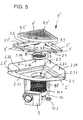
- the gutter 1 'shown in Fig. 5 is intended for an arrangement in a shower room corner, which is formed by two substantially mutually perpendicular room walls.
- the gutter 1 ' in turn comprises a gutter module 2', a frame 3 'and a grate 4'.
- the bottom of the trough-shaped channel 2.1 of the trough module 2 ' has a drain opening 2.2, on which a discharge nozzle 2.21 is arranged.
- the outlet connection 2.21 opens into a trap 5, which corresponds to the odor trap 5 shown in Fig. 1.
- the drain opening 2.2 is provided with a removable hair sieve 8.
- the trough module 2 ' is viewed in plan view formed substantially quarter-circular. It has a circumferential horizontal channel flange 2.3 ', which consists of two straight, equally long, mutually perpendicular flange sections 2.31, 2.32 and a connecting them quarter-circular arc-shaped flange 2.33.
- the mounting holes 2.36 are formed as slots and extend vertically.
- the feet 10 have with the underside of the channel module 2 'connected threaded sleeves 11', are screwed into the threaded rods 10.1.
- the lower ends of the threaded rods 10.1 are in turn provided with plate-shaped foot elements 10.2.
- the frame 3 'and the grate 4' are also formed in a quarter-circle. Also in this embodiment, the frame 3 'has a peripheral flange 3.1', wherein the channel flange 2.3 'again wider than the frame flange 3.1' is formed.
- the frame 3 ' has on its three inner sides in each case a projection 3.2, 3.3, 3.5 which projects downwards and engages in the channel 2.1 of the channel module 2' when the frame 3 'is placed on the channel module 2'.
- the grate 4 'according to FIG. 5 has a perforated plate-shaped section 4.1', at the edge of a downwardly directed collar 4.2 'integrally connected. When inserted, the grate 4 'is supported with its peripheral collar 4.2' on the projections 3.21, 3.31 of the frame 3 'and held laterally by the frame.
- the rings arranged around the frame 3 'and latched with a near the outer edge of the frame 3' circumferential lip 3.4.
- the support means 9 ' correspond in function and configuration the support means 9 according to Figures 1, 2 and 4.
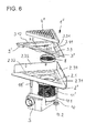
- Fig. 6 differs from that of Fig. 5 only in that the trough module 2 ", the frame 3 '' and the grate 4 '' are not designed quarter-circle, but triangular.
- the frame 3" of this triangular gutter 1 '' corresponds to an isosceles triangle, wherein the two flange 3.11 and 3.12 of the frame 3 '', which face the walls of the corner, at right angles to each other.
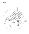
- the present invention also includes the alternative of supporting the grate 4, 4 'or 4 "on the bottom of the cup-shaped channel 2.1.
- the grate 4 (or 4 'or 4'') is provided on its underside with a plurality of, for example, eight adjustable feet on which the grate rests stably in the gutter module (see Fig. 7).
- the feet 4.3 are height adjustable mounted on the grate 4.
- the level of the grate 4, 4 'or 4' ' can be adjusted by means of the adjustable feet relative to the trough module 2, 2' and 2 '' and the frame 3, 3 'and 3 ".
- the embodiment of the invention is not limited to the embodiments described above. Rather, further variants are conceivable which make use of the inventive concept given in the claims, even if the design is fundamentally different.
- other height-adjustable support means may be mounted on the underside of the frame flange 3.1 instead of the interchangeable support means 9, 9 '.
- threaded bolts with threaded sleeves screwed thereon-similar to the leveling feet according to FIG. 7- can be attached to the frame flange 3.1.
- corresponding threaded sleeves can be attached to the underside of the frame flange 3.1, in which on the channel flange 2.3 supportable threaded bolt can be screwed.
Abstract
Description
Die Erfindung betrifft eine Ablaufrinne sowie ein System zur Bildung eines Wasserablaufs, vorzugsweise für bodengleiche Duschen.The invention relates to a gutter and a system for forming a water drain, preferably for floor-level showers.
Ablaufrinnen für bodengleiche Duschen sind an sich bekannt. Sie umfassen einen Rost und ein unterhalb des Rosts angeordnetes, mit einem Ablauf verbundenes Rinnenmodul. Das Wasser aus der Dusche fließt dann über den üblicherweise gefliesten Boden und gelangt durch den Rost in das Rinnenmodul. Die Rinne des Rinnenmoduls leitet das Wasser letztlich zu einem Ablauf.Gullies for floor-level showers are known. They comprise a grate and a gutter module arranged below the grate and connected to a drain. The water from the shower then flows over the usually tiled floor and passes through the grate in the gutter module. The gutter of the gutter module ultimately leads the water to a drain.
Derartige Ablaufrinnen werden in den Boden eingebaut, wobei der Rost nach oben in etwa mit den Bodenbelag der Dusche abschließt. Der Einbau einer Duschwanne oder dergleichen ist nicht erforderlich, so dass auch die umlaufende Kante der Duschwanne, die häufig störend wirkt, entfällt.Such gutters are installed in the ground, with the grate up close to about the floor covering the shower. The installation of a shower tray or the like is not required, so that the peripheral edge of the shower tray, which often acts disturbing, is eliminated.
Ablaufrinnen für bodengleiche Duschen müssen in besonderer weise an den speziellen Einbauort angepasst werden, da der Unterbau, der Bodenbelag aus Fliesen oder Naturstein und der Anschluss an die Abwasserleitung von Fall zu Fall unterschiedlich ausfallen können und meist nur eine niedrige Bauhöhe zur Verfügung steht. Vor allem sollen derartige Ablaufrinnen einen sicheren Ablauf des Wassers gewährleisten, bei dem die untere Bodenkonstruktion, bestehend aus Estrich und ggf. Wärmedämmung, nicht durchnässt wird. Zudem sollen sie ästhetisch in den Boden integriert sein.Drainage channels for floor-level showers must be specially adapted to the specific installation location, since the base, the floor covering made of tiles or natural stone and the connection to the sewer can vary from case to case and usually only a low overall height is available. Above all, such gutters should ensure safe drainage of the water, in which the lower floor construction, consisting of screed and possibly thermal insulation, not gets soaked. In addition, they should be aesthetically integrated into the ground.
Dies führt dazu, dass eine Vielzahl unterschiedlicher Ablaufrinnen produziert und auf Lager gehalten wird. Der Anwendungsbereich einer bestimmten herkömmlichen Ablaufrinne ist dabei in der Regel begrenzt.This results in a large number of different gutters being produced and kept in stock. The scope of a particular conventional gutter is limited in the rule.
Ferner muss zum bodengleichen Einbau herkömmlicher Ablaufrinnen sehr genau gearbeitet werden, damit ein ebener Boden und ein guter optischer Eindruck erzielt wird. Die Installation herkömmlicher Ablaufrinnen nimmt daher relativ viel Zeit in Anspruch, was entsprechend hohen Arbeitskosten bedeutet.Furthermore, the floor-level installation of conventional gutters must be worked very carefully, so that a level bottom and a good visual impression is achieved. The installation of conventional gutters therefore takes a relatively long time, which means correspondingly high labor costs.
Der vorliegenden Erfindung liegt die Aufgabe zugrunde, eine Ablaufrinne für bodengleiche Duschen zu schaffen, welche einfach, schnell und sehr flexibel in unterschiedlichen Böden eingebaut werden kann.The present invention has for its object to provide a gutter for floor-level showers, which can be installed easily, quickly and very flexible in different soils.
Diese Aufgabe wird durch eine Ablaufrinne mit den Merkmalen des Anspruchs 1 gelöst.This object is achieved by a gutter with the features of
Die erfindungsgemäße Ablaufrinne umfasst neben einem Rinnenmodul und einem Rost zusätzlich einen Rahmen. Das Rinnenmodul weist eine muldenförmige Rinne mit einer Ablauföffnung auf. Der Rahmen kann auf das Rinnenmodul aufgesetzt werden, wobei der die Ablaufrinne als solche nach oben abschließende Rost in den Rahmen eingesetzt wird.The gutter according to the invention comprises in addition to a gutter module and a grate in addition to a frame. The gutter module has a trough-shaped channel with a drain opening. The frame can be placed on the gutter module, wherein the gutter as such upwards final grate is inserted into the frame.
Beim Aufsetzen des Rahmens auf das Rinnenmodul gelangen wenigstens zwei Vorsprünge, die an benachbarten und/oder an einander gegenüberliegenden Seiten des Rahmens angeordnet sind, in Eingriff mit der Rinne. Die Vorsprünge sind so zueinander angeordnet, dass der auf das Rinnenmodul aufgesetzte Rahmen im Eingriffsbereich der Vorsprünge um mindestens 5 mm, vorzugsweise um mindestens 10 mm in einer im wesentlichen horizontalen Richtung relativ zum Rinnenmodul verschiebbar ist. Es kommt daher nicht zu einem Reibschluss oder einem Verkeilen zwischen dem Rahmen und dem Rinnenmodul. Vielmehr sitzt der Rahmen locker auf dem Rinnenmodul auf und kann deshalb leicht in Richtung des einen oder des anderen Vorsprungs verschoben werden, bis einer der Vorsprünge an dem Rinnenmodul bzw. der Rinne zur Anlage kommt und dadurch ein weiteres Verschieben des Rahmens verhindert wird.When placing the frame on the gutter module reach at least two projections, which are arranged on adjacent and / or on opposite sides of the frame are in engagement with the gutter. The projections are arranged relative to one another such that the frame placed on the channel module is displaceable in the engagement region of the projections by at least 5 mm, preferably by at least 10 mm, in a substantially horizontal direction relative to the channel module. There is therefore no frictional connection or wedging between the frame and the gutter module. Rather, the frame sits loosely on the gutter module and can therefore be easily moved in the direction of one or the other projection until one of the projections on the gutter module or the gutter comes to rest and thereby further displacement of the frame is prevented.
Im Ergebnis ist somit, nachdem das Rinnenmodul mehr oder weniger endgültig in den Boden eingebaut ist, noch eine Justierung des Rahmens und damit des Rosts möglich. Mit anderen Worten kann zunächst der Einbau des Rinnenmoduls unkompliziert und schnell erfolgen, da dessen Position nur in etwa mit einer vorbestimmten Einbauposition übereinstimmen muss. Dies wirkt sich jedoch nicht negativ auf die Optik und die Funktion der späteren bodengleichen Dusche aus, da anschließend über den Rahmen noch eine Feinjustierung vorgenommen werden kann. Besonders vorteilhaft ist es, dass die Feinjustierung des Rahmens sehr viel einfacher bewerkstelligt werden kann als eine Feinjustierung beim Einbau des Rinnenmoduls. Durch die Möglichkeit einer solchen Feinjustierung ist die Verwendung der erfindungsgemäßen Ablaufrinne sehr viel flexibler möglich, da die Lage des Rosts in gewissen Grenzen ausgeglichen werden kann. Auch kann auf diese Weise ein gewisser Ausgleich hinsichtlich der üblicherweise verwendeten Fliesen bzw. Natursteinplatten stattfinden, so dass der Rahmen mit dem Rost etwa fluchtend bzw. symmetrisch in das angrenzende Fugengitter eingepasst werden kann.As a result, therefore, after the gutter module is more or less permanently installed in the ground, still an adjustment of the frame and thus the rust possible. In other words, the installation of the trough module can initially be uncomplicated and fast, since its position only has to coincide approximately with a predetermined installation position. However, this does not have a negative effect on the look and the function of the later floor-level shower, because then on the frame can still be made a fine adjustment. It is particularly advantageous that the fine adjustment of the frame can be accomplished much easier than a fine adjustment during installation of the channel module. Due to the possibility of such a fine adjustment, the use of the gutter according to the invention is much more flexible possible because the position of the grate can be compensated within certain limits. Also can take place in this way a certain balance in terms of commonly used tiles or natural stone slabs, so that the frame with the rust about can be fitted flush or symmetrical in the adjacent joint grid.
Vorzugsweise handelt es sich bei Ablaufrinnen bodengleicher Duschen um solche einer länglichen Bauart mit zwei einander gegenüberliegenden Längsseiten und zwei einander gegenüberliegenden Querseiten. Dementsprechend ist dann sowohl das Rinnenmodul als auch der Rahmen und der Rost länglich ausgebildet, wobei jedes Bauteil entsprechende Längs- und Querseiten aufweist. Die Erfindung ist jedoch nicht auf derartige Ablaufrinnen begrenzt. Die Ablaufrinnen können nahezu beliebige Formen aufweisen. Lediglich die Anordnung der Vorsprünge ist an die bevorzugte(n) Ausgleichsrichtung(en) und die entsprechenden Abmessungen der Rinne im Bereich der späteren Vorsprünge anzupassen. Geometrische Formen sind dabei genauso möglich wie natürliche bzw. organische Formen. Bei rund ausgebildeten Ablaufrinnen ist der äußere Abstand der wenigstens zwei Vorsprünge kleiner als der Durchmesser der Rinne des Rinnenmoduls.Preferably, drainage channels of floor-level showers are those of an elongate design with two longitudinal sides opposite one another and two transverse sides lying opposite one another. Accordingly, then both the gutter module and the frame and the grate is elongated, each component having respective longitudinal and transverse sides. However, the invention is not limited to such gutters. The gutters can have almost any shape. Only the arrangement of the projections is to be adapted to the preferred compensation direction (s) and the corresponding dimensions of the channel in the region of the later projections. Geometric forms are just as possible as natural or organic forms. In the case of round gutters, the outer spacing of the at least two protrusions is smaller than the diameter of the gutter of the gutter module.
Im Zusammenhang insbesondere mit länglichen Ablaufrinnen einer rechteckigen Bauart ist es bevorzugt, wenn der Rahmen einerseits an zwei einander gegenüberliegenden Längsseiten wenigstens zwei Vorsprünge aufweist, deren äußerer Abstand um mindestens 5 mm, vorzugsweise mindestens 10 mm kleiner ist als die Länge der Rinne, und andererseits an zwei einander gegenüberliegenden Querseiten wenigstens zwei Vorsprünge aufweist, deren äußerer Abstand um mindestens 5 mm, vorzugsweise mindestens 10 mm kleiner ist als die Breite der Rinne. Auf diese Weise ist ein Ausgleich oder eine Feinjustierung in einer Längsrichtung und noch dazu alternativ oder zusätzlich in einer Querrichtung möglich.In connection with elongated gutters of a rectangular design in particular, it is preferred if the frame has, on the one hand, at least two projections on two opposite longitudinal sides whose outer spacing is at least 5 mm, preferably at least 10 mm smaller than the length of the gutter, and on the other hand two opposite transverse sides has at least two projections whose outer distance is smaller by at least 5 mm, preferably at least 10 mm than the width of the channel. In this way, a compensation or a fine adjustment in a longitudinal direction and still alternatively or additionally in a transverse direction is possible.
Durch eine Überlagerung beider Bewegungsrichtungen kann der Rahmen auf dem Rinnenmodul bzw. in der Rinne in alle Richtungen parallel zu der Ebene des Bodens bewegt werden.By overlapping both directions of movement, the frame on the gutter module or in the gutter can be moved in all directions parallel to the plane of the ground.
Bei einer weiter bevorzugten Ausführungsform der erfindungsgemäßen Ablaufrinne sind die Vorsprünge im Wesentlichen umlaufend an dem Rahmen vorgesehen. Stoßen die umlaufend angeordneten Vorsprünge an den Kanten des Rahmens aneinander, so ergibt sich letztlich ein einziger umlaufender Vorsprung, der sich aus den einzelnen Vorsprüngen ergibt. In diesem Fall wird eine größere Stabilität nicht nur der Vorsprünge, sondern auch des Rahmens erzielt, wodurch beispielsweise auch Materialkosten eingespart werden können.In a further preferred embodiment of the gutter according to the invention, the projections are provided substantially circumferentially on the frame. If the circumferentially arranged projections abut against one another at the edges of the frame, ultimately a single circumferential projection results, which results from the individual projections. In this case, a greater stability not only of the projections, but also of the frame is achieved, whereby, for example, material costs can be saved.
Besonders bevorzugt ist es, wenn das Rinnenmodul einen Rinnenflansch und der Rahmen einen Rahmenflansch aufweisen, so dass der Rahmenflansch bei aufgesetztem Rahmen den Rinnenflansch zumindest teilweise überdeckt. Der Rahmen kann dann stets sicher auf dem Rinnenmodul abgestützt werden, auch wenn der Rahmen aus der zentralen Lage bis in eine Randlage verschoben wird. Es versteht sich, dass die Breite des Rahmenflanschs dabei an die Differenz zwischen der Breite/Länge der Rinne und den äußeren Abstand der Vorsprünge angepasst ist.It is particularly preferred if the channel module has a channel flange and the frame has a frame flange, so that the frame flange at least partially covers the channel flange when the frame is attached. The frame can then always be securely supported on the gutter module, even if the frame is moved from the central position to a peripheral position. It is understood that the width of the frame flange is adapted to the difference between the width / length of the channel and the outer spacing of the projections.
Um nach dem Einbau des Rinnenmoduls die Lage des Rosts einer Ablaufrinne sowohl in einer Ebene parallel zum Boden als auch in einer Richtung senkrecht dazu anpassen zu können, sieht die Erfindung ferner vor, dass an dem Rahmen oder dem Rinnenmodul wenigstens ein Auflagemittel zur Höhenanpassung des Rahmens über dem Rinnenmodul angebracht werden kann. Bei einem derartigen Auflagemittel handelt es sich mit anderen Worten um eine Art Abstandshalter zwischen dem Rahmen und dem Rinnenmodul. Dadurch kann das Rinnenmodul stets auf die gleiche Weise in den Estrich o.ä. eingebracht werden, wobei für den Fall, dass dickere Fliesen oder dickere Platten aus Naturstein vorgesehen sind, die Höhe des später aufgesetzten Rosts durch das wenigstens eine Auflagemittel, das zwischen dem Rinnenmodul und dem Rahmen vorgesehen wird, einfach angepasst wird. Der auf den Rahmen aufgesetzte Rost schließt dann bündig mit den Fliesen bzw. Natursteinplatten ab. Es versteht sich, dass das wenigstens eine Auflagemittel in diesem Fall Bestandteil der erfindungsgemäßen Ablaufrinne bzw. Bestandteil eines die erfindungsgemäße Ablaufrinne umfassenden Systems ist.In order to be able to adjust the position of the grate of a gutter both in a plane parallel to the ground and in a direction perpendicular thereto after installation of the gutter module, the invention further provides that on the frame or the gutter module at least one support means for height adjustment of the frame can be mounted over the gutter module. In such a support means in other words, it is a kind of spacer between the frame and the gutter module. This allows the gutter module in the same way in the screed o.ä. are introduced, wherein in the event that thicker tiles or thicker plates are provided from natural stone, the height of the later patch rust by the at least one support means, which is provided between the trough module and the frame, is easily adapted. The grid placed on the frame then closes flush with the tiles or natural stone slabs. It is understood that the at least one support means in this case is part of the drainage channel according to the invention or a component of a drainage channel system according to the invention.
Eine besonders hohe Flexibilität wird erreicht, wenn die erfindungsgemäße Ablaufrinne bzw. ein die Ablaufrinne umfassendes System unterschiedliche, in ihren Abmessungen standardisierte Auflagemittel umfasst. Die Auflagemittel können bei dieser besonders bevorzugten Ausgestaltung der Erfindung an verschiedene, häufig verwendete oder standardisierte Fliesenstärken angepasst sein.A particularly high degree of flexibility is achieved if the drainage channel according to the invention or a system comprising the drainage channel comprises different support means standardized in their dimensions. The support means can be adapted in this particularly preferred embodiment of the invention to various, frequently used or standardized tile thicknesses.
Hinsichtlich der Handhabung ist es bevorzugt, wenn das wenigstens eine Auflagemittel mit dem Rahmen oder dem Rinnenmodul verbunden werden kann bevor der Rahmen auf das Rinnenmodul aufgesetzt wird. Besonders bevorzugt ist es, wenn das Auflagemittel mit dem Rahmen oder dem Rinnenmodul ohne spezielles Werkzeug verrastbar ausgebildet ist. Ein ungewolltes Lösen des Auflagemittels wird durch das Verrasten verhindert.In terms of handling, it is preferred if the at least one support means can be connected to the frame or the gutter module before the frame is placed on the gutter module. It is particularly preferred if the support means is designed lockable with the frame or the gutter module without a special tool. Unintentional release of the support means is prevented by the latching.
Darüber hinaus bietet es sich an, dass der Rahmen oder das Rinnenmodul wenigstens eine Lippe zum Einrasten des wenigstens einen Auflagemittels aufweist. Eine derartige Lippe lässt sich konstruktiv einfach realisieren.In addition, it is advisable that the frame or the trough module has at least one lip for engaging the at least one support means. Such a lip can be realized structurally simple.
Wird die Lippe zudem im Wesentlichen umlaufend am Rahmen oder am Rinnenmodul vorgesehen, dann kann der Anwender vor Ort entscheiden, an welchen Stellen das oder die Auflagemittel vorgesehen werden. Zudem erhöht eine umlaufende Lippe die Biegesteifigkeit des Rahmens bzw. Rinnenmoduls.If the lip is also provided essentially peripherally on the frame or on the gutter module, then the user can decide on site at which points the or the support means are provided. In addition, a circumferential lip increases the bending stiffness of the frame or gutter module.
Alternativ kann das wenigstens eine Auflagemittel auch derart ausgebildet sein, dass es an dem Rahmen oder Rinnenmodul reibschlüssig anklemmbar ist. Hierzu kann das Auflagemittel vorzugsweise einen Klemmschlitz aufweisen.Alternatively, the at least one support means may also be designed such that it can be frictionally clamped to the frame or channel module. For this purpose, the support means may preferably have a clamping slot.
Bei einer bevorzugten Ausgestaltung weist das wenigstens eine Auflagemittel im Wesentlichen die Form eines Quaders auf. Das Auflagemittel besteht vorzugsweise aus Kunststoff. Um den Rost in die richtige Lage zu bringen, werden mehrere kompakte Auflagemittel an dem Rahmen oder dem Rinnenmodul vorgesehen, sodass der Rahmen stabil auf dem Rinnenmodul aufsitzt. Alternativ könnte natürlich auch ein umlaufendes Auflagemittel verwendet werden, das allerdings mehr Platz und Material erfordern würde und daher weniger bevorzugt ist.In a preferred embodiment, the at least one support means substantially in the form of a cuboid. The support means is preferably made of plastic. In order to bring the grid in the correct position, several compact support means are provided on the frame or the gutter module, so that the frame sits stably on the gutter module. Alternatively, of course, a circumferential support means could be used, which, however, would require more space and material and is therefore less preferred.
In bevorzugter Ausgestaltung der erfindungsgemäßen Ablaufrinne bzw. eines diese umfassenden Systems weisen die Vorsprünge des Rahmens nach innen abgewinkelte Auskragungen zur Abstützung des Rosts auf. Der Rost wird dann auf die Auskragungen der Vorsprünge aufgesetzt, wobei der Rost seitlich vom Rahmen gehalten wird. Der Rost ist dabei vorzugsweise reibschlüssig im Rahmen eingefasst. Der Rost kann dadurch nicht versehentlich verrutschen und dennoch zu Reinigungszwecken leicht entnommen werden.In a preferred embodiment of the drainage channel according to the invention or a system comprising this, the projections of the frame have inwardly angled projections for supporting the grate. The grate is then placed on the projections of the projections, wherein the grate is held laterally from the frame. Of the Rust is preferably frictionally bordered in the frame. The rust can not accidentally slip and yet be easily removed for cleaning purposes.
Zusätzlich kann auch das Rinnenmodul sowohl in seiner Höhe als auch in seiner Neigung an den Untergrund angepasst werden, wozu nach einer vorteilhaften Ausgestaltung der erfindungsgemäßen Ablaufrinne wenigstens zwei Füße zum Aufstellen des Rinnenmoduls vorgesehen sind. Insbesondere sind vier Füße vorgesehen, die vorzugsweise nahe den Eckbereichen des Rinnenmoduls angeordnet sind. Auf diese Weise wird ein sicherer Stand des Rinnenmoduls erreicht.In addition, the gutter module can be adapted both in its height and in its inclination to the ground, for which purpose according to an advantageous embodiment of the gutter according to the invention at least two feet are provided for setting up the gutter module. In particular, four feet are provided, which are preferably arranged near the corner regions of the channel module. In this way, a secure state of the trough module is achieved.
Das Rinnenmodul ist vorzugsweise durch wenigstens ein Verstellmittel in der Höhe verstellbar, wobei das wenigstens eine Verstellmittel von oberhalb des Rinnenmoduls zum Verstellen zugänglich ist. Dadurch kann das Rinnenmodul zunächst ungefähr ausgerichtet auf dem Untergrund aufgestellt werden, wobei hinterher eine einfache Anpassung von oben erfolgen kann, etwa solange bis das Rinnenmodul exakt in der Waagerechten steht.The gutter module is preferably adjustable in height by at least one adjusting means, wherein the at least one adjusting means is accessible from above the trough module for adjusting. As a result, the gutter module can initially be placed approximately aligned on the ground, with a simple adjustment can be done from the top afterwards, as long as until the gutter module is exactly in the horizontal.
Besonders zweckmäßig ist es dabei, wenn das wenigstens eine Verstellmittel in den wenigstens einen Fuß integriert ist. Der Fuß oder die Füße können dann letztlich in ihrer Länge verändert werden, so dass das auf diesen Füßen aufgestellte Rinnenmodul waagerecht ausgerichtet ist.It is particularly expedient if the at least one adjusting means is integrated in the at least one foot. The foot or feet can then ultimately be changed in length so that the trough module placed on these feet is level.
Eine konstruktiv besonders einfache Lösung wird dadurch erreicht, dass das wenigstens eine Verstellmittel teilweise als eine in einem Gewinde geführte Gewindestange ausgebildet ist. Dabei kann der wenigstens eine Fuß teilweise als Gewindestange gebildet sein, so dass von dem Fuß zugleich zwei Funktionen übernommen werden.A structurally particularly simple solution is achieved in that the at least one adjusting means partially as a guided in a thread Threaded rod is formed. In this case, the at least one foot may be partially formed as a threaded rod, so that two functions are taken over by the foot at the same time.
Alternativ oder zusätzlich kann das wenigstens eine Verstellmittel auch als ein ablängbares Höhenausgleichsstück ausgebildet sein, dass je nach Verwendung auf die erforderliche Länge abgelängt wird. Dabei ist das Verstellelement beispielsweise ein Teil des Fußes, so dass das Ablängen des Verstellelements einem Verkürzen des Fußes gleichkommt.Alternatively or additionally, the at least one adjusting means can also be designed as a length-adjustable height compensation piece which is cut to the required length depending on the use. In this case, the adjustment is, for example, a part of the foot, so that the cutting of the adjustment equal to a shortening of the foot.
Für den Fall, dass sowohl ein ablängbares als auch ein teilweise als Gewindestange ausgebildetes Verstellelement vorgesehen sind, kann es so sein, dass die Grobeinstellung durch das Ablängen des ablängbaren Verstellelements und die anschließende Feineinstellung durch entsprechendes Drehen des teilweise als Gewindestange ausgebildeten Verstellelements erfolgt.In the event that both a ablängbares and partially designed as a threaded rod adjusting element are provided, it may be the case that the coarse adjustment is carried out by the cutting of the ablängbaren adjustment and the subsequent fine adjustment by appropriate rotation of the partially formed as a threaded rod adjustment.
Weitere bevorzugte und vorteilhafte Ausgestaltungen der erfindungsgemäßen Ablaufrinne sind in der nachfolgenden Beschreibung und den beigefügten Unteransprüchen angegeben.Further preferred and advantageous embodiments of the gutter according to the invention are given in the following description and the appended subclaims.
Im Folgenden wird die Erfindung anhand einer mehrere Ausführungsbeispiele darstellenden Zeichnung näher erläutert. In der Zeichnung zeigen
- Fig. 1
- eine erfindungsgemäße längliche Ablaufrinne in einer perspektivischen Explosionsdarstellung;
- Fig. 2
- eine Ablaufrinne entsprechend der Ablaufrinne der Fig. 1 in einer Expolsionsdarstellung;
- Fig. 3
- einen Abschnitt einer erfindungsgemäßen länglichen Ablaufrinne in perspektivischer Ansicht;
- Fig. 4
- eine erfindungsgemäße längliche Ablaufrinne ohne Rost in perspektivischer Ansicht;
- Fig. 5
- eine erfindungsgemäße viertelkreisförmige Ablaufrinne in einer perspektivischen Explosionsdarstellung;
- Fig. 6
- eine erfindungsgemäße dreieckige Ablaufrinne in einer perspektivischen Explosionsdarstellung; und
- Fig. 7
- eine perspektivische Detailansicht eines Rostes einer erfindungsgemäßen Ablaufrinne.
- Fig. 1
- an elongated drainage channel according to the invention in a perspective exploded view;
- Fig. 2
- a gutter according to the gutter of Figure 1 in an exploded view.
- Fig. 3
- a section of an elongated gutter according to the invention in a perspective view;
- Fig. 4
- an elongated gutter according to the invention without rust in perspective view;
- Fig. 5
- a quarter-circle-shaped gutter according to the invention in a perspective exploded view;
- Fig. 6
- a triangular gutter according to the invention in a perspective exploded view; and
- Fig. 7
- a detailed perspective view of a grate of a gutter according to the invention.
Fig. 1 zeigt die Einzelteile eines Systems zur Bildung eines Wasserablaufs mit einer Ablaufrinne 1 für bodengleiche Duschen. Das System umfasst zumindest ein Rinnenmodul 2, einen Rahmen 3 und einen Rost 4, wobei an dem Rinnenmodul 2 ein Geruchverschluss 5 angeschlossen ist. Der Geruchverschluss 5 ist ein aus Kunststoff hergestelltes Spritzgießteil und weist einen im Wesentlichen zylindrischen Rohrabschnitt 5.1 auf, dessen Mantel gewellt ausgebildet ist. Der zylindrische Rohrabschnitt 5.1 kann bei Bedarf auf der Baustelle abgelängt (gekürzt) werden, wozu ein geeignetes Schneidwerkzeug in einem Wellental des Rohrabschnittes 5.1 angesetzt und entlang der angrenzenden Welle geführt werden kann. Am Ablaufstutzen 5.2 des Geruchverschlusses 5 ist ein abgewinkeltes Rohrstück 6 schwenkbar anschließbar (vgl. Fig. 2).Fig. 1 shows the items of a system for forming a water drain with a
Mit 7 ist eine schalenförmige Abdeckung bezeichnet, die zum Schutz des Rinnenmoduls 2 vor einer Verstopfung durch Estrich, Mörtel oder andere Materialien während der Montage des Rinnenmoduls 2 bzw. der Bauphase dient und in dieser den Rinnenflansch 2.3 vor Verunreinigungen schützt. Hierzu wird die Abdeckung 7 formschlüssig in das Rinnenmodul 2 eingesetzt. Das Rinnenmodul 2 weist eine schalenförmige Rinne 2.1 mit einer Ablauföffnung 2.2 auf, wobei der Rinnenboden zur Ablauföffnung 2.2 hin mit Gefälle ausgebildet ist. An die Ablauföffnung 2.2 schließt sich ein Ablaufstutzen 2.21 an. In die Ablauföffnung bzw. den Ablaufstutzen 2.21 ist ein Haarsieb 8 einsetzbar (vgl. Fig. 2).Denoted by 7 is a cup-shaped cover which serves to protect the
Auf das längliche Rinnenmodul 2 kann nach Entfernen der Abdeckung 7 der Rahmen 3 aufgesetzt werden, der wie das Rinnenmodul 2 einen umlaufenden Flansch aufweist. Der Rinnenflansch 2.3 ist dabei breiter als der Rahmenflansch 3.1 ausgebildet. Der Rahmen 3 weist an seinen vier Innenseiten jeweils einen Vorsprung 3.2, 3.3 auf, der nach unten vorsteht und in die Rinne 2.1 des Rinnenmoduls 2 eingreift, wenn der Rahmen 3 auf das Rinnenmodul 2 gesetzt wird.After removal of the
Die längsseitigen Vorsprünge 3.2 des Rahmens 3 weisen nach innen abgewinkelte Auskragungen 3.21 auf, die der Abstützung des Rosts 4 dienen. Die zueinander beabstandeten Auskragungen 3.21 stehen zahnartig an den Vorsprüngen 3.2 vor. Der Rost 4 besitzt ein im Wesentlichen U-förmiges Querschnittsprofil mit einer gelochten Grundplatte 4.1 und zwei davon abgewinkelten, nach unten gerichteten Schenkeln 4.2, die vorzugsweise ungelocht sind. Im eingesetzten Zustand wird der Rost 4 mit seinen Schenkeln 4.2 auf den Auskragungen 3.21 des Rahmens 3 abgestützt und gleichzeitig seitlich vom Rahmen 3 gehalten.The longitudinal projections 3.2 of the
Zur Anpassung der Einbauhöhe des Rahmens 3 bzw. Rostes 4 an unterschiedliche Fliesenstärken bzw. unterschiedlich dicke Natursteinplatten sind mehrere Auflagemittel 9 vorgesehen, die rings um den Rahmen 3 angeordnet und mit einer im Bereich des äußeren Randes des Rahmens 3 umlaufenden Lippe 3.4 verrastet sind.To adapt the installation height of the
Die Auflagemittel 9 haben im Wesentlichen die Form eines Quaders und sind aus Kunststoff gefertigt. Sie können allerdings auch eine andere geometrische Form aufweisen, beispielsweise die Form eines Zylinders. Sie weisen jeweils einen Schlitz auf, in den die Lippe 3.4 des Rahmens 3 bei der Verrastung eingreift. Alternativ kann auch eine reibschlüssige Klemmverbindung von Auflagemittel 9 und Rahmen 3 vorgesehen werden, wobei der Schlitz dann als Klemmschlitz für die darin einzusetzende Rahmenlippe 3.4 ausgeführt ist.The support means 9 have substantially the shape of a cuboid and are made of plastic. However, they can also have a different geometric shape, for example the shape of a cylinder. They each have a slot into which engages the lip 3.4 of the
Im zusammengebauten Zustand der Ablaufrinne 1 liegen die Auflagemittel 9 auf dem Rinnenflansch 2.3 auf, so dass der Flansch 3.1 des Rahmens 3 etwas weiter von dem Rinnenmodul 2 nach oben beabstandet ist. Die Auflagemittel 9 können dabei in ihrer Dicke so gewählt werden, dass eine Anpassung an die jeweilige Dicke der vorgesehenen Bodenfliesen bzw. Natursteinplatten erzielt wird. Hierzu werden verschieden dicke Auflagemittel 9 der Ablaufrinne 1 beigepackt, die beispielsweise eine Dicke von 4,5 mm, 7,5 mm, 10,5 mm und 13,5 mm aufweisen können.In the assembled state of the
Insbesondere aus der Fig. 4 ist zu entnehmen, dass die Vorsprünge 3.2, 3.3, von denen man dort lediglich den Vorsprung 3.2 an der rechten Längsseite und den Vorsprung 3.3 an der hinteren Querseite des Rahmens 3 erkennt, bis in die Rinne 2.1 hinein reichen, so dass der Rahmen 3 auf diese Weise auf dem Rinnenmodul 2 angeordnet soweit verschieblich ist, dass die üblichen Abweichungen bei der Montage des Rinnenmoduls 2 sowie beim Verlegen der Bodenfliesen bzw. Natursteinplatten ausgeglichen werden können.In particular, from Fig. 4 it can be seen that the projections 3.2, 3.3, of which one recognizes there only the projection 3.2 on the right longitudinal side and the projection 3.3 on the rear transverse side of the
Die Höhe und die Neigung des Rinnenmoduls 2 kann mit Hilfe von verstellbaren Füßen 10, die an beiden Enden des Rinnenmoduls 2 vorgesehen sind, verändert werden. Dazu wird das Rinnenmodul 2 zunächst mit zwei Fußhalterungen 11 versehen. Die Fußhalterungen 11 bestehen jeweils aus einem U-förmigen Metallprofilträger, der stirnseitig durch Wandabschnitte 11.1 verstärkt ist. Die Wandabschnitte 11.1 sind vorzugsweise durch Abkanten des Basisabschnitts 11.2 des Profilmaterials gebildet und zwischen die parallel zueinander verlaufenden Stege 11.3, 11.4 gebogen.The height and the inclination of the
An der Unterseite der Rinne 2.1, nahe den Enden des länglichen Rinnenmoduls 2, sind Klemmelemente 2.4 zur lösbaren Befestigung der Fußhalterungen 11 versehen (vgl. Fig. 2). Die Klemmelemente 2.4 sind klammerartig ausgebildet und mit einem ihrer beiden Enden an der Unterseite des Rinnenbodens angeschweißt. Ihr anderes Ende kann elastisch von der Unterseite des Rinnenbodens abgebogen werden, um den oberen Steg 11.3 der Fußhalterung 11 zwischen dem Klemmelement 2.4 und dem Boden des Rinnenmoduls 2 einklemmen zu können.At the bottom of the channel 2.1, near the ends of the
In den Stegen 11.3, 11.4 der Fußhalterungen 11 sind nahe den stirnseitigen Wandabschnitten 11.1 Durchgangslöcher 11.5, 11.6 vorgesehen. Die beiden oberen Durchgangslöcher 11.5 fluchten mit den unteren Durchgangslöchern 11.6, wobei an letzteren jeweils eine Mutter 11.7 zum Einschrauben einer als Verstellmittel dienenden Gewindestange 10.1 angeordnet ist. Anstelle der Verwendung von Muttern können die unteren Durchgangslöchern 11.6 auch als Gewindebohrungen ausgeführt werden.In the webs 11.3, 11.4 of the
Die Gewindestangen 10.1 sind an ihren unteren Enden jeweils mit tellerförmigen Fußelement 10.2 versehen, das vorzugsweise aus Kunststoff hergestellt ist und eine darin eingefasste Mutter 10.3 zur Verbindung von Fußelement 10.2 und Gewindestange 10.1 aufweist. Das obere Ende der Gewindestange 10.1 weist ein Mehrkantloch, vorzugsweise ein Sechskantloch 10.4 auf, um die Gewindestange 10.1 mit einem entsprechenden Werkzeug (Vierkant- bzw. Sechskantschlüssel) verstellen zu können.The threaded rods 10.1 are provided at their lower ends in each case with a plate-shaped base element 10.2, which is preferably made of plastic and has a nut 10.3 enclosed therein for the connection of foot element 10.2 and threaded rod 10.1. The upper end of the threaded rod 10.1 has a polygonal hole, preferably a hexagonal hole 10.4 in order to adjust the threaded rod 10.1 with a corresponding tool (square or hex wrench).
Die Verstellmittel bzw. Gewindestangen 10.1 sind zum Verstellen von oberhalb des Rinnenmoduls 2 aus zugänglich. Hierzu ist der Rinnenflansch 2.3 mit Durchgangslöchern 2.5 versehen, die bezüglich der am Rinnenboden angebrachten Klemmelemente 2.4 so angeordnet sind, dass sie mit den Durchgangslöchern 11.5, 11.6 der am Rinnenmodul 2 klemmend befestigten Fußelemente 11 in fluchtende Überdeckung gebracht werden können.The adjusting or threaded rods 10.1 are accessible for adjusting from above the
Nachdem die Höhe und die Neigung des Rinnenmoduls 2 durch Verstellen der Füße 10 bzw. Gewindestangen 10.1 bezüglich des Rohbodens eingestellt ist, werden die Öffnungen 2.5 des Rinnenflansches 2.3 vorzugsweise mit abnehmbaren Verschlußelementen (nicht dargestellt) versehen. Danach kann bis auf Höhe des Rinnenflanschs 2.3 eine Schicht Estrich o.ä. auf den Rohboden aufgebracht werden.After the height and the inclination of the
Nach der Abdichtung von Fußboden und Rinnenflansch mit Flüssigfolie wird der Rahmen 3 auf das Rinnenmodul 2 aufgesetzt. Da die äußeren Abstände der jeweils einander gegenüberliegenden Vorsprünge 3.2, 3.3 erheblich kleiner sind als die Breite bzw. die Länge der Rinne 2.1 des Rinnenmoduls 2, liegt der Rahmen 3 in gewissen Grenzen verschieblich auf dem Rinnenflansch 2.3 auf.After sealing the floor and gutter flange with liquid foil, the
Dies ermöglicht dann eine Anpassung der Lage des Rahmens 3 bezüglich angrenzend verlegter Fliesen, ohne dass die Lage des Rinnenmoduls 2 nachträglich verändert werden muss. Es wird der Rahmen 3 einfach in die gewünschte Position gebracht, bevor dort dann der die Ablaufrinne 1 nach oben abschließende Rost 4 angebracht wird. Wie weit der Rahmen 3 verschoben werden kann, hängt letztlich von dem äußeren Abstand der Vorsprünge 3.2, 3.3 ab. Einige Millimeter, vorzugsweise 10 mm, weiter vorzugsweise 5 mm, sind hier jedoch zumeist ausreichend.This then allows an adjustment of the position of the
Das erfindungsgemäße System ist in den Figuren 3 und 4 im teilweise zu einer Ablaufrinne 1 zusammengebauten Zustand dargestellt, wobei der Rost 4 der Übersichtlichkeit halber nicht dargestellt ist. Man erkennt in Fig. 4, wie die Vorsprünge 3.2, 3.3 der hinteren Längsseite und der oberen Querseite in die Rinne hinein ragen, so dass der Rahmen 3 einerseits verschieblich ist aber dennoch im Rinnenmodul 2 gehalten wird. Im übrigen erkennt man besonders gut in Fig. 3 die einzelnen, den Füßen 10 der Anordnung zugeordneten Löcher 2.5 im Rinnenflansch 2.3, durch die ein Werkzeug zur Höhenverstellung der Füße 10 hindurch geführt werden kann.The system according to the invention is shown in Figures 3 and 4 in partially assembled to a
Die in Fig. 5 dargestellte Ablaufrinne 1' ist für eine Anordnung in einer Duschraumecke bestimmt, die durch zwei im Wesentlichen rechtwinklig zueinander verlaufende Raumwände gebildet ist. Die Ablaufrinne 1' umfasst wiederum ein Rinnenmodul 2', einen Rahmen 3' und einen Rost 4'. Der Boden der muldenförmigen Rinne 2.1 des Rinnenmoduls 2' weist eine Ablauföffnung 2.2 auf, an der ein Ablaufstutzen 2.21 angeordnet ist. Der Ablaufstutzen 2.21 mündet in einen Geruchverschluss 5, der dem in Fig. 1 gezeigten Geruchverschluss 5 entspricht. Die Ablauföffnung 2.2 ist mit einem herausnehmbaren Haarsieb 8 versehen.The gutter 1 'shown in Fig. 5 is intended for an arrangement in a shower room corner, which is formed by two substantially mutually perpendicular room walls. The gutter 1 'in turn comprises a gutter module 2', a frame 3 'and a grate 4'. The bottom of the trough-shaped channel 2.1 of the trough module 2 'has a drain opening 2.2, on which a discharge nozzle 2.21 is arranged. The outlet connection 2.21 opens into a
Das Rinnenmodul 2' ist in Draufsicht betrachtet im Wesentlichen viertelkreisförmig ausgebildet. Es weist einen umlaufenden horizontalen Rinnenflansch 2.3' auf, der aus zwei geraden, gleichlangen, rechtwinklig zueinander verlaufenden Flanschabschnitten 2.31, 2.32 und einem diese verbindenden viertelkreisbogenförmigen Flanschabschnitt 2.33 besteht.The trough module 2 'is viewed in plan view formed substantially quarter-circular. It has a circumferential horizontal channel flange 2.3 ', which consists of two straight, equally long, mutually perpendicular flange sections 2.31, 2.32 and a connecting them quarter-circular arc-shaped flange 2.33.
An den beiden geraden Flanschabschnitten 2.31, 2.32 sind nach oben abgewinkelte, im wesentlichen vertikal verlaufende Sockelabschnitte 2.34, 2.35 ausgebildet, die der Abdichtung der Raumecke gegen Eindringen von Nässe dienen und zudem Befestigungslöcher 2.36 aufweisen. Die Befestigungslöcher 2.36 sind als Langlöcher ausgebildet und erstrecken sich vertikal.At the two straight flange sections 2.31, 2.32 upwardly angled, substantially vertically extending base sections 2.34, 2.35 are formed, which serve to seal the corner of the room against the ingress of moisture and also have mounting holes 2.36. The mounting holes 2.36 are formed as slots and extend vertically.
An der Unterseite des Rinnenmoduls 2' sind höhenverstellbare Füße 10 angebracht. Die Füße 10 weisen mit der Unterseite des Rinnenmoduls 2' verbundene Gewindehülsen 11' auf, in die Gewindestangen 10.1 eingeschraubt sind. Die unteren Enden der Gewindestangen 10.1 sind wiederum mit tellerförmigen Fußelementen 10.2 versehen.At the bottom of the channel module 2 'height
Der Rahmen 3' und der Rost 4' sind ebenfalls viertelkreisförmig ausgebildet. Auch bei diesem Ausführungsbeispiel weist der Rahmen 3' einen umlaufenden Flansch 3.1' auf, wobei der Rinnenflansch 2.3' wiederum breiter als der Rahmenflansch 3.1' ausgebildet ist. Der Rahmen 3' weist an seinen drei Innenseiten jeweils einen Vorsprung 3.2, 3.3, 3.5 auf, der nach unten vorsteht und in die Rinne 2.1 des Rinnenmoduls 2' eingreift, wenn der Rahmen 3' auf das Rinnenmodul 2' gesetzt wird.The frame 3 'and the grate 4' are also formed in a quarter-circle. Also in this embodiment, the frame 3 'has a peripheral flange 3.1', wherein the channel flange 2.3 'again wider than the frame flange 3.1' is formed. The frame 3 'has on its three inner sides in each case a projection 3.2, 3.3, 3.5 which projects downwards and engages in the channel 2.1 of the channel module 2' when the frame 3 'is placed on the channel module 2'.
Wie bei der länglichen Ablaufrinne gemäß Fig. 1 weisen auch die Vorsprünge 3.2, 3.3, 3.5 des viertelkreisförmigen Rahmens 3' nach innen abgewinkelte Auskragungen 3.21, 3.31 auf, die der Abstützung des Rosts 4' dienen. Der Rost 4' gemäß Fig. 5 hat einen gelochten plattenförmigen Abschnitt 4.1', an dessen Rand sich ein nach unten gerichteter Kragen 4.2' einstückig anschließt. Im eingesetzten Zustand wird der Rost 4' mit seinem umlaufenden Kragen 4.2' auf den Auskragungen 3.21, 3.31 des Rahmens 3' abgestützt und seitlich vom Rahmen gehalten.As with the elongated gutter according to FIG. 1, the projections 3.2, 3.3, 3.5 of the quarter-circle-shaped frame 3 'inwardly angled projections 3.21, 3.31, which serve to support the grate 4'. The grate 4 'according to FIG. 5 has a perforated plate-shaped section 4.1', at the edge of a downwardly directed collar 4.2 'integrally connected. When inserted, the grate 4 'is supported with its peripheral collar 4.2' on the projections 3.21, 3.31 of the frame 3 'and held laterally by the frame.
Zur Anpassung der Einbauhöhe des Rahmens 3' und des Rosts 4' an unterschiedlich dicke Fliesen oder Natursteinplatten sind - wie beim zuvor beschriebenen Ausführungsbeispiel - mehrere Auflagemittel 9' vorgesehen, die rings um den Rahmen 3' angeordnet und mit einer nahe dem äußeren Rand des Rahmens 3' umlaufenden Lippe 3.4 verrastet sind. Die Auflagemittel 9' entsprechen in Funktion und Ausgestaltung den Auflagemittel 9 gemäß den Figuren 1, 2 und 4.To adapt the installation height of the frame 3 'and the grate 4' to different thickness tiles or natural stone slabs - as in the embodiment described above - several support means 9 'is provided, the rings arranged around the frame 3 'and latched with a near the outer edge of the frame 3' circumferential lip 3.4. The support means 9 'correspond in function and configuration the support means 9 according to Figures 1, 2 and 4.
Das in Fig. 6 dargestellte Ausführungsbeispiel unterscheidet sich von dem der Fig. 5 lediglich dadurch, dass das Rinnenmodul 2", der Rahmen 3'' und der Rost 4'' nicht viertelkreisförmig, sondern dreieckig gestaltet sind. Der Rahmen 3" dieser dreieckigen Ablaufrinne 1'' entspricht einem gleichschenkligen Dreieck, wobei die beiden Flanschabschnitte 3.11 und 3.12 des Rahmens 3'', die den Wänden der Raumecke zugewandt sind, im rechten Winkel zueinander verlaufen.The embodiment shown in Fig. 6 differs from that of Fig. 5 only in that the
Die an den Vorsprüngen 3.2, 3.3, 3.5 der Rahmen 3, 3', 3'' ausgebildeten Auskragungen 3.21, 3.31 sind nicht zwingend erforderlich. Die vorliegende Erfindung umfasst auch die Alternative, den Rost 4, 4' oder 4'' auf dem Boden der schalenförmigen Rinne 2.1 abzustützen. In diesem Fall ist der Rost 4 (bzw. 4' oder 4'') an seiner Unterseite mit mehreren, beispielsweise acht Stellfüßen versehen, auf denen der Rost stabil in dem Rinnenmodul aufliegt (vgl. Fig. 7). Die Stellfüße 4.3 sind dabei höhenverstellbar am Rost 4 befestigt. Sie weisen eine an die Unterseite des Rosts 4 angeschweißte oder angeformte Gewindestange 4.31 auf, auf die eine hülsenförmige Sechskantmutter 4.32 aufgeschraubt ist. An der Unterseite der Sechskantmutter 4.32 ist eine abgerundete Auflagescheibe 4.33 angebrachtThe protrusions 3.21, 3.31 formed on the projections 3.2, 3.3, 3.5 of the
Das Niveau des Rosts 4, 4' oder 4'' lässt sich mittels der Stellfüße relativ zum Rinnenmodul 2, 2' bzw. 2'' sowie zum Rahmen 3, 3' bzw. 3" justieren.The level of the
Die Ausführung der Erfindung ist nicht auf die vorstehend beschriebenen Ausführungsbeispiele beschränkt. Vielmehr sind weitere Varianten denkbar, die auch bei grundsätzlich abweichender Gestaltung von dem in den Ansprüchen angegebenen Erfindungsgedanken Gebrauch machen. So können anstelle der auswechselbaren Auflagemittel 9, 9' auch andere höhenverstellbare Auflagemittel an der Unterseite des Rahmenflansches 3.1 angebracht sein. Beispielsweise können Gewindebolzen mit darauf aufgeschraubten Gewindehülsen - ähnlich den Stellfüßen gemäß Fig. 7 - am Rahmenflansch 3.1 angebracht sein. Ebenso können auch entsprechende Gewindehülsen an der Unterseite des Rahmenflansches 3.1 angebracht sein, in die auf dem Rinnenflansch 2.3 abstützbare Gewindebolzen einschraubbar sind.The embodiment of the invention is not limited to the embodiments described above. Rather, further variants are conceivable which make use of the inventive concept given in the claims, even if the design is fundamentally different. Thus, other height-adjustable support means may be mounted on the underside of the frame flange 3.1 instead of the interchangeable support means 9, 9 '. For example, threaded bolts with threaded sleeves screwed thereon-similar to the leveling feet according to FIG. 7-can be attached to the frame flange 3.1. Likewise, corresponding threaded sleeves can be attached to the underside of the frame flange 3.1, in which on the channel flange 2.3 supportable threaded bolt can be screwed.
Claims (22)
dadurch gekennzeichnet,
characterized,
dadurch gekennzeichnet,
dass die Vorsprünge (3.2, 3.3) im Wesentlichen umlaufend an dem Rahmen (3) vorgesehen sind.Drainage channel according to claim 1 or 2,
characterized,
in that the projections (3.2, 3.3) are provided substantially circumferentially on the frame (3).
dadurch gekennzeichnet,
characterized,
dadurch gekennzeichnet,
dass an dem Rahmen (3) oder dem Rinnenmodul (2) wenigstens ein Auflagemittel (9) zur Höhenanpassung des Rahmens (3) über dem Rinnenmodul (2) anbringbar ist.Drainage channel according to one of claims 1 to 4,
characterized,
in that at least one bearing means (9) for adjusting the height of the frame (3) above the channel module (2) can be attached to the frame (3) or the channel module (2).
dadurch gekennzeichnet,
dass das wenigstens eine Auflagemittel (9) mit dem Rahmen (3) oder dem Rinnenmodul (2) verrastbar ist.Drainage channel according to claim 5,
characterized,
in that the at least one support means (9) can be latched to the frame (3) or the gutter module (2).
dadurch gekennzeichnet,
dass der Rahmen (3) oder das Rinnenmodul (2) wenigstens eine Lippe (3.4) zum Einrasten des wenigstens einen Auflagemittels (9) aufweist.Drainage channel according to claim 6,
characterized,
comprises that the frame (3) or the channel module (2) at least one lip (3.4) for locking the at least one support means (9).
dadurch gekennzeichnet,
dass die Lippe (3.4) im Wesentlichen umlaufend am Rahmen (3) oder am Rinnenmodul (2) vorgesehen ist.Drainage channel according to claim 7,
characterized,
that the lip (3.4) is provided substantially circumferentially on the frame (3) or the channel module (2).
dadurch gekennzeichnet,
dass das wenigstens eine Auflagemittel (9) an dem Rahmen (3) oder dem Rinnenmodul (2) reibschlüssig anklemmbar ist.Drainage channel according to claim 5,
characterized,
in that the at least one support means (9) can be frictionally clamped to the frame (3) or the gutter module (2).
dadurch gekennzeichnet,
dass das wenigstens eine Auflagemittel (9) einen Klemmschlitz aufweist.Drainage channel according to claim 9,
characterized,
that the at least one support means (9) comprises a clamping slot.
dadurch gekennzeichnet,
dass das wenigstens eine Auflagemittel (9) im Wesentlichen die Form eines Quaders oder Zylinders aufweist.Drainage channel according to one of claims 5 to 10,
characterized,
in that the at least one support means (9) has substantially the shape of a cuboid or cylinder.
dadurch gekennzeichnet,
an der Unterseite des Rahmenflansches (3.1, 3.1') höhenverstellbare Auflagemittel angebracht sind, über die der Rahmen (3, 3') auf dem Rinnenflansch abgestützt ist.Drainage channel according to claim 4,
characterized
on the underside of the frame flange (3.1, 3.1 ') height-adjustable support means are mounted, via which the frame (3, 3') is supported on the channel flange.
dadurch gekennzeichnet,
dass die Vorsprünge (3.2, 3.3) des Rahmens (3) nach innen abgewinkelte Auskragungen (3.21) zur Abstützung des Rosts (4) aufweisen.Drainage channel according to one of claims 1 to 12,
characterized,
that the projections (3.2, 3.3) comprise the frame (3) inwardly angled projections (3.21) for supporting the grid (4).
dadurch gekennzeichnet,
dass der Rost (4) mit höhenverstellbaren Füßen (4.3) versehen ist, über die er in der Rinne (2.1) des Rinnenmoduls (2) abgestützt ist.Drainage channel according to one of claims 1 to 12,
characterized,
that the grate (4) is provided with height-adjustable feet (4.3), via which it is supported in the channel (2.1) of the channel module (2).
dadurch gekennzeichnet,
dass das Rinnenmodul (2) mit wenigstens zwei Füßen (10) versehen ist.Drainage channel according to one of claims 1 to 14,
characterized,
in that the gutter module (2) is provided with at least two feet (10).
dadurch gekennzeichnet,
characterized,
dadurch gekennzeichnet,
dass das wenigstens eine Verstellmittel (10.1) in wenigstens einen der Füße (10) integriert ist.Drainage channel according to claims 15 and 16,
characterized,
in that the at least one adjusting means (10.1) is integrated in at least one of the feet (10).
dadurch gekennzeichnet,
dass an der Unterseite des Rinnenmoduls (2) wenigstens eine Fußhalterung (11) befestigbar ist, wobei die Fußhalterung (11) mit wenigstens einer Gewindebohrung oder einer Mutter (11.7) versehen ist, in die eine als Verstellmittel dienende Gewindestange (10.1) eingeschraubt ist.Drainage channel according to one of claims 1 to 17,
characterized,
in that at least one foot holder (11) can be fastened to the underside of the gutter module (2), wherein the foot holder (11) is provided with at least one threaded bore or nut (11) into which a threaded rod (10.1) serving as an adjusting means is screwed.
dadurch gekennzeichnet,
dass die Gewindestange (10.1) über eine in dem Rinnenflansch (2.3) ausgebildete Öffnung (2.5) von oberhalb des Rinnenmoduls (2) zugänglich ist.Drainage channel according to claim 18,
characterized,
that the threaded rod (10.1) a in the Rinnenflansch (2.3) shaped opening (2.5) from above the channel module (2) is accessible.
dadurch gekennzeichnet,
dass die Öffnung (2.5) mit einem abnehmbaren Verschlußelement versehen ist.Drainage channel according to claim 19,
characterized,
that the opening (2.5) is provided with a removable closure element.
dadurch gekennzeichnet,
dass die Unterseite des Rinnenmoduls (2) mit wenigstens einem Klemmelement (2.4) zur lösbaren Befestigung einer Fußhalterung (11) versehen ist.Drainage channel according to one of claims 1 to 20,
characterized,
in that the underside of the channel module (2) is provided with at least one clamping element (2.4) for the detachable fastening of a foot holder (11).
Priority Applications (1)
| Application Number | Priority Date | Filing Date | Title |
|---|---|---|---|
| PL07100703T PL1818464T3 (en) | 2006-02-08 | 2007-01-17 | Floor drain, especially for showers |
Applications Claiming Priority (1)
| Application Number | Priority Date | Filing Date | Title |
|---|---|---|---|
| DE202006002077U DE202006002077U1 (en) | 2006-02-08 | 2006-02-08 | Drainage channel and system for forming a drain, preferably for floor-level showers |
Publications (2)
| Publication Number | Publication Date |
|---|---|
| EP1818464A1 true EP1818464A1 (en) | 2007-08-15 |
| EP1818464B1 EP1818464B1 (en) | 2011-03-02 |
Family
ID=37963511
Family Applications (1)
| Application Number | Title | Priority Date | Filing Date |
|---|---|---|---|
| EP07100703A Active EP1818464B1 (en) | 2006-02-08 | 2007-01-17 | Floor drain, especially for showers |
Country Status (6)
| Country | Link |
|---|---|
| EP (1) | EP1818464B1 (en) |
| AT (1) | ATE500390T1 (en) |
| DE (2) | DE202006002077U1 (en) |
| DK (1) | DK1818464T3 (en) |
| ES (1) | ES2359089T3 (en) |
| PL (1) | PL1818464T3 (en) |
Cited By (8)
| Publication number | Priority date | Publication date | Assignee | Title |
|---|---|---|---|---|
| EP1905908A3 (en) * | 2006-09-22 | 2008-12-31 | Dallmer GmbH & Co. KG | Drainage device |
| WO2010093290A1 (en) * | 2009-02-10 | 2010-08-19 | Purus Ab | Drain and inlet member for drain |
| DE202009005060U1 (en) | 2009-07-24 | 2010-12-30 | Gutjahr, Walter | Connection frame for a floor drain and floor drain |
| DE202010002763U1 (en) | 2010-02-24 | 2011-07-27 | Schlüter-Systems Kg | floor drain |
| CN102720264A (en) * | 2012-07-12 | 2012-10-10 | 苏州沃特节水产品有限公司 | High water seal inner core type interlayer drainage control device |
| CN103104025A (en) * | 2013-02-06 | 2013-05-15 | 开平市新明光五金制品有限公司 | Floor drain with garbage can |
| WO2013185030A1 (en) * | 2012-06-07 | 2013-12-12 | Scott Stonecipher | Trench drain |
| US11773580B2 (en) | 2019-12-18 | 2023-10-03 | Schluter Systems L.P. | Frame for a floor drain |
Families Citing this family (11)
| Publication number | Priority date | Publication date | Assignee | Title |
|---|---|---|---|---|
| DE102007058299B4 (en) * | 2007-12-05 | 2021-09-23 | Tece Gmbh | Installation method for installing a floor-level drainage channel in a floor and installation kit for carrying out the method |
| FR2928156B1 (en) * | 2008-02-29 | 2014-05-23 | Farhooman Davoudi | BONDE ASSEMBLY / SIPHON OF EVACUATION CONSISTS OF SEVERAL GUARDS OF WATER |
| DE102008052285B4 (en) * | 2008-10-18 | 2014-01-30 | Dallmer Gmbh & Co. Kg | draining device |
| ES1071622Y (en) * | 2009-12-21 | 2010-06-15 | Jimten Sa | ADJUSTABLE SUPPORT FOR TRIANGULAR SINK |
| DE102011113381A1 (en) | 2011-09-16 | 2013-03-21 | Sanitärtechnik Eisenberg GmbH | Covering structure for surface drainage device used in e.g. sanitary area, has arrangement unit that is arranged with a holding and/or positioning elements for holding and/or positioning cover portion with two major surfaces |
| DE202011105715U1 (en) | 2011-09-16 | 2011-11-16 | Sanitärtechnik Eisenberg GmbH | Cover for a surface dewatering device, surface dewatering device and use of a surface dewatering device |
| DE102013107840A1 (en) * | 2013-07-23 | 2015-01-29 | ACO Severin Ahlmann GmbH & Co Kommanditgesellschaft | off device |
| DE202017101845U1 (en) * | 2017-03-30 | 2018-07-03 | Ardex Anlagen Gmbh | Height adjustment device for a gutter cover |
| USD913462S1 (en) | 2017-11-08 | 2021-03-16 | Sympateco, Inc. | Shower basin |
| US10888200B1 (en) | 2017-11-08 | 2021-01-12 | Sympateco, Inc. | Shower basin |
| USD913463S1 (en) | 2017-11-08 | 2021-03-16 | Sympateco, Inc. | Shower basin |
Citations (2)
| Publication number | Priority date | Publication date | Assignee | Title |
|---|---|---|---|---|
| CH614004A5 (en) | 1977-03-02 | 1979-10-31 | Robert Warthmann | Drainage shaft for carriageways with a concrete substructure |
| WO2001073231A1 (en) | 2000-03-24 | 2001-10-04 | Unidrain A/S | A drain and a building structure having a drain |
Family Cites Families (3)
| Publication number | Priority date | Publication date | Assignee | Title |
|---|---|---|---|---|
| DE4124369A1 (en) * | 1990-08-02 | 1992-02-06 | Passavant Werke | Bath-water drainage channel - is assembled from overlapping sections |
| DE9419373U1 (en) * | 1994-12-05 | 1995-03-16 | Wilhelm Hafner Gmbh | Gutter for laying in a floor |
| DE102004025874A1 (en) * | 2004-05-27 | 2005-12-22 | Dallmer Gmbh & Co. Kg | gutter |
-
2006
- 2006-02-08 DE DE202006002077U patent/DE202006002077U1/en not_active Expired - Lifetime
-
2007
- 2007-01-17 ES ES07100703T patent/ES2359089T3/en active Active
- 2007-01-17 PL PL07100703T patent/PL1818464T3/en unknown
- 2007-01-17 AT AT07100703T patent/ATE500390T1/en active
- 2007-01-17 DK DK07100703.3T patent/DK1818464T3/en active
- 2007-01-17 DE DE502007006572T patent/DE502007006572D1/en active Active
- 2007-01-17 EP EP07100703A patent/EP1818464B1/en active Active
Patent Citations (2)
| Publication number | Priority date | Publication date | Assignee | Title |
|---|---|---|---|---|
| CH614004A5 (en) | 1977-03-02 | 1979-10-31 | Robert Warthmann | Drainage shaft for carriageways with a concrete substructure |
| WO2001073231A1 (en) | 2000-03-24 | 2001-10-04 | Unidrain A/S | A drain and a building structure having a drain |
Cited By (13)
| Publication number | Priority date | Publication date | Assignee | Title |
|---|---|---|---|---|
| EP1905908A3 (en) * | 2006-09-22 | 2008-12-31 | Dallmer GmbH & Co. KG | Drainage device |
| WO2010093290A1 (en) * | 2009-02-10 | 2010-08-19 | Purus Ab | Drain and inlet member for drain |
| US8661574B2 (en) | 2009-02-10 | 2014-03-04 | Purus Ab | Drain and inlet member for drain |
| EP2278081A2 (en) | 2009-07-24 | 2011-01-26 | Walter Gutjahr | Connection frame for a floor drain and floor drain |
| DE202009005060U1 (en) | 2009-07-24 | 2010-12-30 | Gutjahr, Walter | Connection frame for a floor drain and floor drain |
| DE202010002763U1 (en) | 2010-02-24 | 2011-07-27 | Schlüter-Systems Kg | floor drain |
| WO2011104292A1 (en) | 2010-02-24 | 2011-09-01 | Schlüter-Systems Kg | Floor drain having a height-adjustable frame for a grating |
| US9127446B2 (en) | 2010-02-24 | 2015-09-08 | Schluter Systems L.P. | Floor drain |
| US9567738B2 (en) | 2010-02-24 | 2017-02-14 | Schluter Systems L.P. | Floor drain |
| WO2013185030A1 (en) * | 2012-06-07 | 2013-12-12 | Scott Stonecipher | Trench drain |
| CN102720264A (en) * | 2012-07-12 | 2012-10-10 | 苏州沃特节水产品有限公司 | High water seal inner core type interlayer drainage control device |
| CN103104025A (en) * | 2013-02-06 | 2013-05-15 | 开平市新明光五金制品有限公司 | Floor drain with garbage can |
| US11773580B2 (en) | 2019-12-18 | 2023-10-03 | Schluter Systems L.P. | Frame for a floor drain |
Also Published As
| Publication number | Publication date |
|---|---|
| DK1818464T3 (en) | 2011-06-06 |
| DE502007006572D1 (en) | 2011-04-14 |
| EP1818464B1 (en) | 2011-03-02 |
| ATE500390T1 (en) | 2011-03-15 |
| DE202006002077U1 (en) | 2007-06-21 |
| ES2359089T3 (en) | 2011-05-18 |
| PL1818464T3 (en) | 2011-07-29 |
Similar Documents
| Publication | Publication Date | Title |
|---|---|---|
| EP1818464B1 (en) | Floor drain, especially for showers | |
| EP1782721B1 (en) | Shower tray with outlet gutter | |
| EP2539517B1 (en) | Floor drain with hight-adjustable frame for a grating | |
| EP2423394B1 (en) | Drainage channel for showers flush with the floor | |
| EP2392739B1 (en) | Drain with height adjustable element | |
| EP3705655B1 (en) | Floor drain for removing water from a walkable floor into a sewer pipe | |
| EP1961879B1 (en) | Drain | |
| EP2289379A2 (en) | Shower tray holder | |
| EP2756137B1 (en) | Drain for a floor-level shower | |
| DE102004049944B4 (en) | Drainage device for installation in a floor opening | |
| EP3216930B1 (en) | Drainage channel | |
| EP2634321A2 (en) | Drain and shower floor element | |
| DE19511206C2 (en) | Building drainage channel | |
| EP2944742B1 (en) | Fixing bracket for stop-end panels | |
| EP3382117B1 (en) | Height-adjusting device for a gutter cover | |
| DE102020101479A1 (en) | Covering device for a drainage channel and channel system | |
| DE19910824A1 (en) | Sheet steel drainage channel has removeable cover grid held on cross webs fitted into sides of channel | |
| DE10112546C2 (en) | Drainage device and method for producing a drainage arrangement | |
| DE202018104969U1 (en) | Storage device for bath or shower utensils | |
| DE102019116655B4 (en) | Installation aid for a floor covering boundary frame of a drain | |
| DE4140802C2 (en) | Raised floor | |
| DE202010000963U1 (en) | Shower drain arrangement | |
| EP4127349A1 (en) | Closure device | |
| WO2002063110A1 (en) | Drainage device and method for production of a drainage device | |
| DE10149830C1 (en) | Sub-frame for bath or shower tub has recesses for height-compensation discs |
Legal Events
| Date | Code | Title | Description |
|---|---|---|---|
| PUAI | Public reference made under article 153(3) epc to a published international application that has entered the european phase |
Free format text: ORIGINAL CODE: 0009012 |
|
| AK | Designated contracting states |
Kind code of ref document: A1 Designated state(s): AT BE BG CH CY CZ DE DK EE ES FI FR GB GR HU IE IS IT LI LT LU LV MC NL PL PT RO SE SI SK TR |
|
| AX | Request for extension of the european patent |
Extension state: AL BA HR MK YU |
|
| 17P | Request for examination filed |
Effective date: 20070824 |
|
| 17Q | First examination report despatched |
Effective date: 20070927 |
|
| AKX | Designation fees paid |
Designated state(s): AT BE BG CH CY CZ DE DK EE ES FI FR GB GR HU IE IS IT LI LT LU LV MC NL PL PT RO SE SI SK TR |
|
| GRAP | Despatch of communication of intention to grant a patent |
Free format text: ORIGINAL CODE: EPIDOSNIGR1 |
|
| RTI1 | Title (correction) |
Free format text: FLOOR DRAIN, ESPECIALLY FOR SHOWERS |
|
| GRAS | Grant fee paid |
Free format text: ORIGINAL CODE: EPIDOSNIGR3 |
|
| GRAA | (expected) grant |
Free format text: ORIGINAL CODE: 0009210 |
|
| AK | Designated contracting states |
Kind code of ref document: B1 Designated state(s): AT BE BG CH CY CZ DE DK EE ES FI FR GB GR HU IE IS IT LI LT LU LV MC NL PL PT RO SE SI SK TR |
|
| REG | Reference to a national code |
Ref country code: GB Ref legal event code: FG4D Free format text: NOT ENGLISH |
|
| REG | Reference to a national code |
Ref country code: CH Ref legal event code: EP |
|
| REG | Reference to a national code |
Ref country code: IE Ref legal event code: FG4D Free format text: LANGUAGE OF EP DOCUMENT: GERMAN |
|
| REG | Reference to a national code |
Ref country code: CH Ref legal event code: NV Representative=s name: TROESCH SCHEIDEGGER WERNER AG |
|
| REF | Corresponds to: |
Ref document number: 502007006572 Country of ref document: DE Date of ref document: 20110414 Kind code of ref document: P |
|
| REG | Reference to a national code |
Ref country code: DE Ref legal event code: R096 Ref document number: 502007006572 Country of ref document: DE Effective date: 20110414 |
|
| REG | Reference to a national code |
Ref country code: ES Ref legal event code: FG2A Ref document number: 2359089 Country of ref document: ES Kind code of ref document: T3 Effective date: 20110506 |
|
| REG | Reference to a national code |
Ref country code: DK Ref legal event code: T3 |
|
| REG | Reference to a national code |
Ref country code: NL Ref legal event code: VDEP Effective date: 20110302 |
|
| PG25 | Lapsed in a contracting state [announced via postgrant information from national office to epo] |
Ref country code: GR Free format text: LAPSE BECAUSE OF FAILURE TO SUBMIT A TRANSLATION OF THE DESCRIPTION OR TO PAY THE FEE WITHIN THE PRESCRIBED TIME-LIMIT Effective date: 20110603 Ref country code: LV Free format text: LAPSE BECAUSE OF FAILURE TO SUBMIT A TRANSLATION OF THE DESCRIPTION OR TO PAY THE FEE WITHIN THE PRESCRIBED TIME-LIMIT Effective date: 20110302 Ref country code: SE Free format text: LAPSE BECAUSE OF FAILURE TO SUBMIT A TRANSLATION OF THE DESCRIPTION OR TO PAY THE FEE WITHIN THE PRESCRIBED TIME-LIMIT Effective date: 20110302 Ref country code: LT Free format text: LAPSE BECAUSE OF FAILURE TO SUBMIT A TRANSLATION OF THE DESCRIPTION OR TO PAY THE FEE WITHIN THE PRESCRIBED TIME-LIMIT Effective date: 20110302 |
|
| REG | Reference to a national code |
Ref country code: PL Ref legal event code: T3 |
|
| LTIE | Lt: invalidation of european patent or patent extension |
Effective date: 20110302 |
|
| PG25 | Lapsed in a contracting state [announced via postgrant information from national office to epo] |
Ref country code: NL Free format text: LAPSE BECAUSE OF FAILURE TO SUBMIT A TRANSLATION OF THE DESCRIPTION OR TO PAY THE FEE WITHIN THE PRESCRIBED TIME-LIMIT Effective date: 20110302 Ref country code: FI Free format text: LAPSE BECAUSE OF FAILURE TO SUBMIT A TRANSLATION OF THE DESCRIPTION OR TO PAY THE FEE WITHIN THE PRESCRIBED TIME-LIMIT Effective date: 20110302 Ref country code: BG Free format text: LAPSE BECAUSE OF FAILURE TO SUBMIT A TRANSLATION OF THE DESCRIPTION OR TO PAY THE FEE WITHIN THE PRESCRIBED TIME-LIMIT Effective date: 20110602 Ref country code: SI Free format text: LAPSE BECAUSE OF FAILURE TO SUBMIT A TRANSLATION OF THE DESCRIPTION OR TO PAY THE FEE WITHIN THE PRESCRIBED TIME-LIMIT Effective date: 20110302 Ref country code: CY Free format text: LAPSE BECAUSE OF FAILURE TO SUBMIT A TRANSLATION OF THE DESCRIPTION OR TO PAY THE FEE WITHIN THE PRESCRIBED TIME-LIMIT Effective date: 20110302 |
|
| REG | Reference to a national code |
Ref country code: IE Ref legal event code: FD4D |
|
| PG25 | Lapsed in a contracting state [announced via postgrant information from national office to epo] |
Ref country code: IE Free format text: LAPSE BECAUSE OF FAILURE TO SUBMIT A TRANSLATION OF THE DESCRIPTION OR TO PAY THE FEE WITHIN THE PRESCRIBED TIME-LIMIT Effective date: 20110302 Ref country code: EE Free format text: LAPSE BECAUSE OF FAILURE TO SUBMIT A TRANSLATION OF THE DESCRIPTION OR TO PAY THE FEE WITHIN THE PRESCRIBED TIME-LIMIT Effective date: 20110302 Ref country code: PT Free format text: LAPSE BECAUSE OF FAILURE TO SUBMIT A TRANSLATION OF THE DESCRIPTION OR TO PAY THE FEE WITHIN THE PRESCRIBED TIME-LIMIT Effective date: 20110704 |
|
| PG25 | Lapsed in a contracting state [announced via postgrant information from national office to epo] |
Ref country code: CZ Free format text: LAPSE BECAUSE OF FAILURE TO SUBMIT A TRANSLATION OF THE DESCRIPTION OR TO PAY THE FEE WITHIN THE PRESCRIBED TIME-LIMIT Effective date: 20110302 Ref country code: IS Free format text: LAPSE BECAUSE OF FAILURE TO SUBMIT A TRANSLATION OF THE DESCRIPTION OR TO PAY THE FEE WITHIN THE PRESCRIBED TIME-LIMIT Effective date: 20110702 Ref country code: SK Free format text: LAPSE BECAUSE OF FAILURE TO SUBMIT A TRANSLATION OF THE DESCRIPTION OR TO PAY THE FEE WITHIN THE PRESCRIBED TIME-LIMIT Effective date: 20110302 Ref country code: RO Free format text: LAPSE BECAUSE OF FAILURE TO SUBMIT A TRANSLATION OF THE DESCRIPTION OR TO PAY THE FEE WITHIN THE PRESCRIBED TIME-LIMIT Effective date: 20110302 |
|
| PLBE | No opposition filed within time limit |
Free format text: ORIGINAL CODE: 0009261 |
|
| STAA | Information on the status of an ep patent application or granted ep patent |
Free format text: STATUS: NO OPPOSITION FILED WITHIN TIME LIMIT |
|
| 26N | No opposition filed |
Effective date: 20111205 |
|
| REG | Reference to a national code |
Ref country code: DE Ref legal event code: R097 Ref document number: 502007006572 Country of ref document: DE Effective date: 20111205 |
|
| PG25 | Lapsed in a contracting state [announced via postgrant information from national office to epo] |
Ref country code: MC Free format text: LAPSE BECAUSE OF NON-PAYMENT OF DUE FEES Effective date: 20120131 |
|
| GBPC | Gb: european patent ceased through non-payment of renewal fee |
Effective date: 20120117 |
|
| PG25 | Lapsed in a contracting state [announced via postgrant information from national office to epo] |
Ref country code: GB Free format text: LAPSE BECAUSE OF NON-PAYMENT OF DUE FEES Effective date: 20120117 |
|
| PG25 | Lapsed in a contracting state [announced via postgrant information from national office to epo] |
Ref country code: TR Free format text: LAPSE BECAUSE OF FAILURE TO SUBMIT A TRANSLATION OF THE DESCRIPTION OR TO PAY THE FEE WITHIN THE PRESCRIBED TIME-LIMIT Effective date: 20110302 |
|
| PG25 | Lapsed in a contracting state [announced via postgrant information from national office to epo] |
Ref country code: LU Free format text: LAPSE BECAUSE OF NON-PAYMENT OF DUE FEES Effective date: 20120117 |
|
| PG25 | Lapsed in a contracting state [announced via postgrant information from national office to epo] |
Ref country code: HU Free format text: LAPSE BECAUSE OF FAILURE TO SUBMIT A TRANSLATION OF THE DESCRIPTION OR TO PAY THE FEE WITHIN THE PRESCRIBED TIME-LIMIT Effective date: 20070117 |
|
| REG | Reference to a national code |
Ref country code: FR Ref legal event code: PLFP Year of fee payment: 10 |
|
| REG | Reference to a national code |
Ref country code: FR Ref legal event code: PLFP Year of fee payment: 11 |
|
| REG | Reference to a national code |
Ref country code: DE Ref legal event code: R082 Ref document number: 502007006572 Country of ref document: DE Representative=s name: COHAUSZ & FLORACK PATENT- UND RECHTSANWAELTE P, DE Ref country code: DE Ref legal event code: R081 Ref document number: 502007006572 Country of ref document: DE Owner name: VIEGA TECHNOLOGY GMBH & CO. KG, DE Free format text: FORMER OWNER: VIEGA GMBH & CO. KG, 57439 ATTENDORN, DE |
|
| REG | Reference to a national code |
Ref country code: AT Ref legal event code: PC Ref document number: 500390 Country of ref document: AT Kind code of ref document: T Owner name: VIEGA TECHNOLOGY GMBH & CO. KG, DE Effective date: 20170512 |
|
| REG | Reference to a national code |
Ref country code: FR Ref legal event code: TP Owner name: VIEGA TECHNOLOGY GMBH & CO. KG, DE Effective date: 20171013 |
|
| REG | Reference to a national code |
Ref country code: ES Ref legal event code: PC2A Owner name: VIEGA TECHNOLOGY GMBH & CO. KG Effective date: 20180108 |
|
| REG | Reference to a national code |
Ref country code: FR Ref legal event code: PLFP Year of fee payment: 12 |
|
| REG | Reference to a national code |
Ref country code: CH Ref legal event code: PUE Owner name: VIEGA TECHNOLOGY GMBH AND CO. KG, DE Free format text: FORMER OWNER: VIEGA GMBH AND CO. KG, DE |
|
| PGFP | Annual fee paid to national office [announced via postgrant information from national office to epo] |
Ref country code: FR Payment date: 20210118 Year of fee payment: 15 |
|
| PGFP | Annual fee paid to national office [announced via postgrant information from national office to epo] |
Ref country code: ES Payment date: 20210218 Year of fee payment: 15 Ref country code: BE Payment date: 20210118 Year of fee payment: 15 |
|
| PGFP | Annual fee paid to national office [announced via postgrant information from national office to epo] |
Ref country code: AT Payment date: 20220125 Year of fee payment: 16 |
|
| REG | Reference to a national code |
Ref country code: BE Ref legal event code: MM Effective date: 20220131 |
|
| PG25 | Lapsed in a contracting state [announced via postgrant information from national office to epo] |
Ref country code: FR Free format text: LAPSE BECAUSE OF NON-PAYMENT OF DUE FEES Effective date: 20220131 Ref country code: BE Free format text: LAPSE BECAUSE OF NON-PAYMENT OF DUE FEES Effective date: 20220131 |
|
| REG | Reference to a national code |
Ref country code: ES Ref legal event code: FD2A Effective date: 20230228 |
|
| PG25 | Lapsed in a contracting state [announced via postgrant information from national office to epo] |
Ref country code: ES Free format text: LAPSE BECAUSE OF NON-PAYMENT OF DUE FEES Effective date: 20220118 |
|
| PGFP | Annual fee paid to national office [announced via postgrant information from national office to epo] |
Ref country code: DK Payment date: 20230127 Year of fee payment: 17 Ref country code: CH Payment date: 20230126 Year of fee payment: 17 |
|
| PGFP | Annual fee paid to national office [announced via postgrant information from national office to epo] |
Ref country code: PL Payment date: 20230113 Year of fee payment: 17 Ref country code: IT Payment date: 20230126 Year of fee payment: 17 Ref country code: DE Payment date: 20230124 Year of fee payment: 17 |
|
| REG | Reference to a national code |
Ref country code: AT Ref legal event code: MM01 Ref document number: 500390 Country of ref document: AT Kind code of ref document: T Effective date: 20230117 |
|
| PG25 | Lapsed in a contracting state [announced via postgrant information from national office to epo] |
Ref country code: AT Free format text: LAPSE BECAUSE OF NON-PAYMENT OF DUE FEES Effective date: 20230117 |