EP1817552B1 - Elements de detection situes sur une meme structure pour capteur en quadrature - Google Patents
Elements de detection situes sur une meme structure pour capteur en quadrature Download PDFInfo
- Publication number
- EP1817552B1 EP1817552B1 EP05852314.3A EP05852314A EP1817552B1 EP 1817552 B1 EP1817552 B1 EP 1817552B1 EP 05852314 A EP05852314 A EP 05852314A EP 1817552 B1 EP1817552 B1 EP 1817552B1
- Authority
- EP
- European Patent Office
- Prior art keywords
- sensing element
- sensing
- leadframe structure
- target
- sensor
- Prior art date
- Legal status (The legal status is an assumption and is not a legal conclusion. Google has not performed a legal analysis and makes no representation as to the accuracy of the status listed.)
- Expired - Lifetime
Links
Images


Classifications
-
- G—PHYSICS
- G01—MEASURING; TESTING
- G01P—MEASURING LINEAR OR ANGULAR SPEED, ACCELERATION, DECELERATION, OR SHOCK; INDICATING PRESENCE, ABSENCE, OR DIRECTION, OF MOVEMENT
- G01P3/00—Measuring linear or angular speed; Measuring differences of linear or angular speeds
- G01P3/42—Devices characterised by the use of electric or magnetic means
- G01P3/44—Devices characterised by the use of electric or magnetic means for measuring angular speed
- G01P3/48—Devices characterised by the use of electric or magnetic means for measuring angular speed by measuring frequency of generated current or voltage
- G01P3/481—Devices characterised by the use of electric or magnetic means for measuring angular speed by measuring frequency of generated current or voltage of pulse signals
- G01P3/488—Devices characterised by the use of electric or magnetic means for measuring angular speed by measuring frequency of generated current or voltage of pulse signals delivered by variable reluctance detectors
-
- G—PHYSICS
- G01—MEASURING; TESTING
- G01D—MEASURING NOT SPECIALLY ADAPTED FOR A SPECIFIC VARIABLE; ARRANGEMENTS FOR MEASURING TWO OR MORE VARIABLES NOT COVERED IN A SINGLE OTHER SUBCLASS; TARIFF METERING APPARATUS; MEASURING OR TESTING NOT OTHERWISE PROVIDED FOR
- G01D11/00—Component parts of measuring arrangements not specially adapted for a specific variable
- G01D11/24—Housings ; Casings for instruments
-
- G—PHYSICS
- G01—MEASURING; TESTING
- G01D—MEASURING NOT SPECIALLY ADAPTED FOR A SPECIFIC VARIABLE; ARRANGEMENTS FOR MEASURING TWO OR MORE VARIABLES NOT COVERED IN A SINGLE OTHER SUBCLASS; TARIFF METERING APPARATUS; MEASURING OR TESTING NOT OTHERWISE PROVIDED FOR
- G01D5/00—Mechanical means for transferring the output of a sensing member; Means for converting the output of a sensing member to another variable where the form or nature of the sensing member does not constrain the means for converting; Transducers not specially adapted for a specific variable
- G01D5/12—Mechanical means for transferring the output of a sensing member; Means for converting the output of a sensing member to another variable where the form or nature of the sensing member does not constrain the means for converting; Transducers not specially adapted for a specific variable using electric or magnetic means
- G01D5/14—Mechanical means for transferring the output of a sensing member; Means for converting the output of a sensing member to another variable where the form or nature of the sensing member does not constrain the means for converting; Transducers not specially adapted for a specific variable using electric or magnetic means influencing the magnitude of a current or voltage
- G01D5/142—Mechanical means for transferring the output of a sensing member; Means for converting the output of a sensing member to another variable where the form or nature of the sensing member does not constrain the means for converting; Transducers not specially adapted for a specific variable using electric or magnetic means influencing the magnitude of a current or voltage using Hall-effect devices
- G01D5/145—Mechanical means for transferring the output of a sensing member; Means for converting the output of a sensing member to another variable where the form or nature of the sensing member does not constrain the means for converting; Transducers not specially adapted for a specific variable using electric or magnetic means influencing the magnitude of a current or voltage using Hall-effect devices influenced by the relative movement between the Hall device and magnetic fields
-
- G—PHYSICS
- G01—MEASURING; TESTING
- G01D—MEASURING NOT SPECIALLY ADAPTED FOR A SPECIFIC VARIABLE; ARRANGEMENTS FOR MEASURING TWO OR MORE VARIABLES NOT COVERED IN A SINGLE OTHER SUBCLASS; TARIFF METERING APPARATUS; MEASURING OR TESTING NOT OTHERWISE PROVIDED FOR
- G01D5/00—Mechanical means for transferring the output of a sensing member; Means for converting the output of a sensing member to another variable where the form or nature of the sensing member does not constrain the means for converting; Transducers not specially adapted for a specific variable
- G01D5/12—Mechanical means for transferring the output of a sensing member; Means for converting the output of a sensing member to another variable where the form or nature of the sensing member does not constrain the means for converting; Transducers not specially adapted for a specific variable using electric or magnetic means
- G01D5/244—Mechanical means for transferring the output of a sensing member; Means for converting the output of a sensing member to another variable where the form or nature of the sensing member does not constrain the means for converting; Transducers not specially adapted for a specific variable using electric or magnetic means influencing characteristics of pulses or pulse trains; generating pulses or pulse trains
- G01D5/245—Mechanical means for transferring the output of a sensing member; Means for converting the output of a sensing member to another variable where the form or nature of the sensing member does not constrain the means for converting; Transducers not specially adapted for a specific variable using electric or magnetic means influencing characteristics of pulses or pulse trains; generating pulses or pulse trains using a variable number of pulses in a train
- G01D5/2451—Incremental encoders
-
- G—PHYSICS
- G01—MEASURING; TESTING
- G01P—MEASURING LINEAR OR ANGULAR SPEED, ACCELERATION, DECELERATION, OR SHOCK; INDICATING PRESENCE, ABSENCE, OR DIRECTION, OF MOVEMENT
- G01P3/00—Measuring linear or angular speed; Measuring differences of linear or angular speeds
- G01P3/42—Devices characterised by the use of electric or magnetic means
- G01P3/44—Devices characterised by the use of electric or magnetic means for measuring angular speed
- G01P3/48—Devices characterised by the use of electric or magnetic means for measuring angular speed by measuring frequency of generated current or voltage
- G01P3/481—Devices characterised by the use of electric or magnetic means for measuring angular speed by measuring frequency of generated current or voltage of pulse signals
- G01P3/487—Devices characterised by the use of electric or magnetic means for measuring angular speed by measuring frequency of generated current or voltage of pulse signals delivered by rotating magnets
Definitions
- Embodiments are generally related to sensing methods and systems. Embodiments are also related to quadrature sensor methods and systems. Embodiments are additionally related to Hall effect sensing devices and speed and direction sensors.
- position sensors Many different types have been implemented in commercial, industrial and consumer applications. Some position sensors are intended to detect the movement of a target along a linear path while others detect the rotation of a target, such as a gear with a plurality of teeth, about an axis of rotation.
- the target and sensor can be arranged so that the target is provided with a plurality of magnetic poles that are sensed by a magnetically sensitive component.
- the sensor may be provided with a biasing magnet and the target can comprise a plurality of ferromagnetic discontinuities, such as gear teeth, that are sensed by the device.
- Quadrature sensing involves the use of two signals that are offset from each other by 90 degrees so that a comparison of the signals will provide meaningful information with regard to the position of a target.
- Quadrature sensors generally provide two outputs that are 90 degrees out of phase. The rising and falling edges, of the output signals are generally utilized to determine the speed while the phase shift between the two output signals indicates direction of movement or rotation of the target.
- the two outputs can be obtained from two sensing elements that are physically spaced at a set distance to match an application-specific target.
- the spacing of the sensing elements with respect to one another and the absolute placement of the sensing elements within the sensor package are critical to sensor's proper functioning. Maintaining the placement of the individual sensing elements often requires significant mechanical keying that is costly and inaccurate. Such mechanical features may also need to be recreated for each application. The physical size of the two sensing elements and associated mechanical features also limits how small the overall sensor can be made.
- US patent 5719496A discloses a dual-element proximity sensor for sensing the direction of rotation of a ferrous target wheel.
- the proximity sensor includes a bar magnet having opposing North and South poles and two magnetic responsive sensors disposed on a lateral face of the magnet between the opposing North and South poles and a pair of corresponding flux concentrators, configured such that the magnetic responsive sensors are sandwiched between the magnet and the flux concentrators along a lateral face of the magnet between opposing pole faces forming a dual-element sensor assembly.
- the present invention provides for a sensor system and a corresponding method as claimed in any of the accompanying claims.
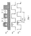
- FIG. 1 illustrates an example phase shift between a first signal 104 and a second signal 106, which can be generated by a quadrature sensor system, in accordance with embodiments of the present invention.
- a plurality of target features (teeth and slots) are depicted in FIG. 1 .
- the teeth are assumed to possess a length of X and the slots are assumed to possess a length of Y.
- Signal 104 represents Output Signal A and signal 106 represents Output Signal B.
- "X" represents a length 108 while “Y” represents a length 110.
- "X" represents a length 112 and "Y” represents a length 114.
- Lengths 110,114 each possess a length Y.
- phase shift between signal 104 (i.e., Signal A) and signal 106 (i.e., Signal B) is approximately equal to 1 ⁇ 2 the average feature width (e.g., approximately X/2 mm), or 1 ⁇ 2 the average feature width plus the slot width and the tooth width (e.g., approximately X/2 +Y+Xmm).
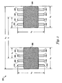
- FIG. 2 illustrates a quadrature sensor system 200, which can be implemented in accordance with a first embodiment.
- System 200 includes a first sensor element 202 and a second sensor element 203.
- Sensor element 202 includes a plurality of pins 204, 206, 208, 210, 214, 216, 218, and 220.
- Sensor element 203 includes a plurality of pins 222, 224, 226, 228, 230, 232, 234, and 236.
- Each sensor element 202 and 203 can be implemented, for example, as an 8-pin SOIC sensing package containing one or more sensing elements thereof (e.g., Hall-effect sensing elements).
- Sensor elements 202 and 203 can be co-located in a common package (e.g., a chip carrier).
- Sensor element 202 possesses a length X3.
- Sensor element 203 also possesses a length X 3 .
- One half the length of sensor packages 202 and 203 is represented in FIG. 2 as X 1 .
- the entire distance from one end of sensor element 203 to the other end of sensor element 202 is represented by variable X 4 .
- the width of each package from pin end to pin end is represented by the variable X 2 .
- the center of the magnetic sensing element is assumed to be in the center of each package. Therefore the distance between the centerline of sensor element 202 to the centerline of sensor element 203 is expressed by variable X.
- the Phase shift between the output signals is directly a function of distance X as well as the rotational alignment of the elements with respect to the target.
- Sensor elements 202 and 203 can be implemented as Hall- effect elements, which rely on the reaction between a current flowing between a first set of contacts and an orthogonally applied magnetic field to generate a voltage across a second set of contacts.
- Hall-effect elements are generally fabricated using a lightly doped n-type layer for heightened sensitivity to variations in magnetic field intensity.
- An example of a Hall-effect element, which can be adapted for use with one or more of the embodiments described herein is disclosed in U.S. Patent No. 6,492,697 .
- sensing elements 202 and 203 with respect to one another and to a common data point provides very accurate and precise tolerances through standard die placement (e.g., pick-and-place). Changing the sensing element spacing for application specific targets is simply a matter of implementing a change in the die placement in the package.
- FIG. 3 illustrates a quadrature sensor system 300, which can be implemented in accordance with a second embodiment.
- similar or identical parts or elements are generally indicated by identical reference numerals.
- two separate sensor elements 202 and 203 are co-located with respect to one another and a common data point.
- the width of each sensing element 202 and 203 from pin to pin is represented by the variable Y 1
- one half the distance (width) from the center of each package or sensor element 202, 203 to respective pins thereof is represented by the variable Y 2 .
- the distance between the end of pins 214, 216, 218, 220 of sensor element 202 and the end of pins 22, 224, 226, 228 of sensor element 203 is represented by the variable Y 3 .
- the center of the magnetic sensing element is assumed to be in the center of each package. Therefore the distance between the centerline of sensor element 202 to the centerline of sensor element 203 is expressed by the expression X/2.
- the Phase shift between the output signals is directly a function of distance X/2 as well as the rotational alignment of the elements with respect to the target.
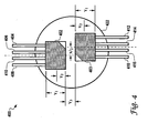
- FIG. 4 illustrates a quadrature sensor system 400, which can be implemented in accordance with a third embodiment.
- a sensor element 402 includes pins 404, 406, 404, 410 while a sensor element 403 includes pins 412, 414, 416, 418.
- the width of each sensor element 402, 403 is represented by the variable Y 1 , while one half of this width is represented by the variable Y 2 .
- Sensor element 402 is located a distance Y 3 from sensor element 403.
- Sensor elements 402 and 403 can be co-located within a circular area 422.
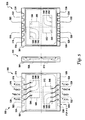
- FIG. 5 illustrates a quadrature sensor system 500, which can be implemented in accordance with a fourth embodiment.
- FIG. 5 illustrates respective top, side and bottom views 502, 504 and 506.
- two sensing element die 508. and 512 can be implemented in a common package 501 that includes pins 514, 516, 518, 520, 524 and pins 526, 528, 530, 532, 534, 536.
- Sensing element die 508 includes pins 538, 540, 542, and 544, which respectively electrically communicate with pins 516, 518, 520, and 522.
- sensing element die 512 includes pins 546, 548, 550, and 552, which respectively electrically communicate with pins 528, 530, 532, and 534.
- Package 501 can be implemented, for example, as a common-lead frame with respective die attached pads, such as, for example, sensing element dies 508 and 512.
- Sensing element die 508 and 512 can be implemented, for example, as Hall-effect sensing element or sensor die.
- the distance between die 508 and 512 is a function of the sensing application and is preferably one-half of the target feature width.
- Package 501 can be configured as a leadless plastic-chip carrier. Several application specific variations can be readily implemented by varying the features between die 508 and 512.
- Fig's 1-4 With other conventional constructions, as depicted in Fig's 1-4, costly and inaccurate mechanical keying features are required in fixtures or mating components.
- the placement of the sensing elements with respect to each other and to a common datum point is held to be very accurate, while promoting precise tolerances (e.g., less than 0.05 mm) through standard placement of die 508 and 512.
- the co-located dies 508 and 512 within a leadless plastic carrier such as package 501 allows the sensing elements 508 and 512 to be located in a very small area, allowing the overall sensor size to be reduced.
- die 508 and 512 can be implemented, for example, as sensor elements 202, 203 of FIGS. 2-3 or sensor elements 402, 403 of FIG. 4 , depending upon design considerations.
- FIG. 6 illustrates a sensing system 600, which can be implemented in accordance with a preferred embodiment.
- System 600 generally includes a sensor element 608 co-located within a circular area 609 with a sensor element 610.
- Sensor elements 608, 610 can be implemented, for example, as sensor elements 202, 203 of FIGS. 2-3 or sensor elements 402, 403 of FIG. 4 and/or sensing die 508 and 512 depicted in FIG. 5 .
- Circular area 609 can be located at one end of a sensor package 601 that includes a sensor body 602, a retaining portion 606 and a sensor portion 604.
- a target 603, which rotates as indicated by arrow 612, contains a central point 614.
- Sensor elements 608 and 610 are therefore co-located in a common package 601 with respect to each other and to a common datum point, such as, for example central point 614.
Landscapes
- Physics & Mathematics (AREA)
- General Physics & Mathematics (AREA)
- Transmission And Conversion Of Sensor Element Output (AREA)
- Hall/Mr Elements (AREA)
Claims (15)
- Système capteur (200), comprenant :une structure formant grille de connexion ;caractérisé par un premier élément capteur (202) et un deuxième élément capteur (203) co-implantés sur ladite structure formant grille de connexion relativement à une cible particulière, le premier élément capteur (202) produisant un premier signal de sortie (104) et le deuxième élément capteur (203) produisant un deuxième signal de sortie (106), un déphasage entre le premier signal de sortie (104) et le deuxième signal de sortie (106) étant fonction d'une distance de séparation entre le premier élément capteur (202) et le deuxième élément capteur (203) ; etdans lequel des applications de détection propres à la cible sont établies en faisant varier une distance entre lesdits premier (202) et deuxième (203) éléments capteurs sur ladite structure formant grille de connexion relativement à un point de référence commun de ceux-ci dans le but de fournir des données de détection de vitesse et de direction à partir desdits premier et deuxième éléments capteurs relativement à ladite cible particulière.
- Système (200) selon la revendication 1, dans lequel ladite distance est au moins la moitié d'une largeur d'un élément caractéristique de cible associé à ladite cible particulière.
- Système (200) selon la revendication 1 ou la revendication 2, dans lequel ledit premier élément capteur (202) est implanté sur un premier plot de fixation de puce attaché à ladite structure formant grille de connexion, et dans lequel ledit deuxième élément capteur (203) est implanté sur un deuxième plot de fixation de puce attaché à ladite structure formant grille de connexion.
- Système (200) selon l'une quelconque des revendications précédentes, dans lequel lesdits premier (202) et deuxième (203) éléments capteurs comprennent des éléments capteurs à effet Hall.
- Système (200) selon l'une quelconque des revendications précédentes, dans lequel ladite structure formant grille de connexion comprend un porte-puces plastique sans conducteur.
- Système (200) selon l'une quelconque des revendications précédentes, dans lequel ladite structure formant grille de connexion comprend une structure formant grille de connexion commune partagée par lesdits premier (202) et deuxième (204) éléments capteurs.
- Système (200) selon l'une quelconque des revendications précédentes, dans lequel ladite distance de séparation est configurée pour être en adéquation avec une cible propre à l'application.
- Système (200) selon l'une quelconque des revendications précédentes, dans lequel ledit déphasage est de 90 degrés relativement à ladite cible particulière.
- Procédé capteur, comprenant l'étape consistant à :procurer une structure formant grille de connexion ;caractérisé par les étapes consistant à co-implanter un premier élément capteur (202) et un deuxième élément capteur (203) sur ladite structure formant grille de connexion relativement à une cible particulière, le premier élément capteur (202) produisant un premier signal de sortie (104) et le deuxième élément capteur (203) produisant un deuxième signal de sortie (106), un déphasage entre le premier signal de sortie (104) et le deuxième signal de sortie (106) étant fonction d'une distance de séparation entre le premier élément capteur (202) et le deuxième élément capteur (203) ; etmettre en oeuvre des applications de détection propres à la cible en faisant varier la distance de séparation entre lesdits premier (202) et deuxième (203) éléments capteurs sur ladite structure formant grille de connexion relativement à un point de référence commun de ceux-ci dans le but de fournir des données de détection de vitesse et de direction à partir desdits premier (202) et deuxième (203) éléments capteurs relativement à ladite cible particulière.
- Procédé selon la revendication 9, comprenant en outre l'étape consistant à fixer ladite distance à au moins la moitié d'une largeur d'un élément caractéristique de cible associé à ladite cible particulière.
- Procédé selon la revendication 9 ou la revendication 10, comprenant en outre les étapes consistant à :implanter ledit premier élément capteur sur un premier plot de fixation de puce attaché à ladite structure formant grille de connexion ; etimplanter ledit deuxième élément capteur sur un deuxième plot de fixation de puce attaché à ladite structure formant grille de connexion.
- Procédé selon l'une quelconque des revendications 9 à 11, comprenant en outre l'étape consistant à configurer lesdits premier et deuxième éléments capteurs de sorte qu'ils comprennent des éléments capteurs à effet Hall.
- Procédé selon l'une quelconque des revendications 9 à 12, comprenant en outre l'étape consistant à configurer ladite structure formant grille de connexion de sorte qu'elle comprenne un porte-puces plastique sans conducteur.
- Procédé selon l'une quelconque des revendications 9 à 13, dans lequel ladite structure formant grille de connexion comprend une structure formant grille de connexion commune partagée par lesdits premier et deuxième éléments capteurs.
- Procédé selon l'une quelconque des revendications 9 à 14, dans lequel ledit déphasage est de 90 degrés relativement à ladite cible particulière.
Applications Claiming Priority (2)
| Application Number | Priority Date | Filing Date | Title |
|---|---|---|---|
| US11/001,409 US7173412B2 (en) | 2004-11-30 | 2004-11-30 | Quadrature sensor systems and methods |
| PCT/US2005/042973 WO2006060330A1 (fr) | 2004-11-30 | 2005-11-29 | Elements de detection situes sur une meme structure pour capteur en quadrature |
Publications (2)
| Publication Number | Publication Date |
|---|---|
| EP1817552A1 EP1817552A1 (fr) | 2007-08-15 |
| EP1817552B1 true EP1817552B1 (fr) | 2014-09-10 |
Family
ID=36087519
Family Applications (1)
| Application Number | Title | Priority Date | Filing Date |
|---|---|---|---|
| EP05852314.3A Expired - Lifetime EP1817552B1 (fr) | 2004-11-30 | 2005-11-29 | Elements de detection situes sur une meme structure pour capteur en quadrature |
Country Status (5)
| Country | Link |
|---|---|
| US (1) | US7173412B2 (fr) |
| EP (1) | EP1817552B1 (fr) |
| KR (1) | KR101220188B1 (fr) |
| CN (1) | CN100565119C (fr) |
| WO (1) | WO2006060330A1 (fr) |
Families Citing this family (10)
| Publication number | Priority date | Publication date | Assignee | Title |
|---|---|---|---|---|
| EP1883787A4 (fr) * | 2005-05-25 | 2013-12-18 | Continental Automotive Canada Inc | Structure magnetique a deux poles comportant deux aimants dephases de 90 degres pour detecter la position dans un actionneur |
| US7361531B2 (en) | 2005-11-01 | 2008-04-22 | Allegro Microsystems, Inc. | Methods and apparatus for Flip-Chip-On-Lead semiconductor package |
| US8486755B2 (en) | 2008-12-05 | 2013-07-16 | Allegro Microsystems, Llc | Magnetic field sensors and methods for fabricating the magnetic field sensors |
| US8629539B2 (en) | 2012-01-16 | 2014-01-14 | Allegro Microsystems, Llc | Methods and apparatus for magnetic sensor having non-conductive die paddle |
| US9666788B2 (en) | 2012-03-20 | 2017-05-30 | Allegro Microsystems, Llc | Integrated circuit package having a split lead frame |
| US9494660B2 (en) | 2012-03-20 | 2016-11-15 | Allegro Microsystems, Llc | Integrated circuit package having a split lead frame |
| US10234513B2 (en) | 2012-03-20 | 2019-03-19 | Allegro Microsystems, Llc | Magnetic field sensor integrated circuit with integral ferromagnetic material |
| US9812588B2 (en) | 2012-03-20 | 2017-11-07 | Allegro Microsystems, Llc | Magnetic field sensor integrated circuit with integral ferromagnetic material |
| US9411025B2 (en) | 2013-04-26 | 2016-08-09 | Allegro Microsystems, Llc | Integrated circuit package having a split lead frame and a magnet |
| US10991644B2 (en) | 2019-08-22 | 2021-04-27 | Allegro Microsystems, Llc | Integrated circuit package having a low profile |
Family Cites Families (15)
| Publication number | Priority date | Publication date | Assignee | Title |
|---|---|---|---|---|
| EP0191223A3 (fr) | 1984-11-09 | 1988-02-24 | The Superior Electric Company | Capteur à couplage magnétique |
| NL8900750A (nl) * | 1989-03-28 | 1990-10-16 | Philips Nv | Inrichting voor het meten van een relatieve verplaatsing. |
| US5451868A (en) * | 1993-05-28 | 1995-09-19 | Arthur Allen Manufacturing Company | Changeable divider and index for a vehicle speed and distance transducer including a hall effect sensor |
| US5719496A (en) * | 1995-06-07 | 1998-02-17 | Durakool Incorporated | Dual-element proximity sensor for sensing the direction of rotation of a ferrous target wheel |
| US6175233B1 (en) * | 1996-10-18 | 2001-01-16 | Cts Corporation | Two axis position sensor using sloped magnets to generate a variable magnetic field and hall effect sensors to detect the variable magnetic field |
| US5746005A (en) * | 1996-10-22 | 1998-05-05 | Powerhorse Corporation | Angular position sensor |
| US5963028A (en) * | 1997-08-19 | 1999-10-05 | Allegro Microsystems, Inc. | Package for a magnetic field sensing device |
| US6133729A (en) * | 1998-06-17 | 2000-10-17 | Arthur Allen Mfg. Co. | Side looking hall-effect vehicle speed sensor with an alignment positioning system |
| US6522130B1 (en) * | 1998-07-20 | 2003-02-18 | Uqm Technologies, Inc. | Accurate rotor position sensor and method using magnet and sensors mounted adjacent to the magnet and motor |
| US6310474B1 (en) * | 1999-03-31 | 2001-10-30 | Delphi Technologies, Inc. | Method and apparatus for detecting the direction of crankshaft rotation during a single tooth/slot transition |
| US6232739B1 (en) * | 2000-02-11 | 2001-05-15 | Delphi Technologies, Inc. | High-resolution incremental position sensor with pulse switching strategy |
| US6492697B1 (en) * | 2000-04-04 | 2002-12-10 | Honeywell International Inc. | Hall-effect element with integrated offset control and method for operating hall-effect element to reduce null offset |
| US20020130657A1 (en) * | 2001-01-29 | 2002-09-19 | Hui Li | Absolute angular position sensor by using gear |
| US6806702B2 (en) * | 2002-10-09 | 2004-10-19 | Honeywell International Inc. | Magnetic angular position sensor apparatus |
| US6946832B2 (en) * | 2003-03-27 | 2005-09-20 | Delphi Technologies, Inc. | Speed and angular position sensing assembly |
-
2004
- 2004-11-30 US US11/001,409 patent/US7173412B2/en not_active Expired - Lifetime
-
2005
- 2005-11-29 KR KR1020077013168A patent/KR101220188B1/ko not_active Expired - Fee Related
- 2005-11-29 CN CNB2005800473466A patent/CN100565119C/zh not_active Expired - Lifetime
- 2005-11-29 WO PCT/US2005/042973 patent/WO2006060330A1/fr not_active Ceased
- 2005-11-29 EP EP05852314.3A patent/EP1817552B1/fr not_active Expired - Lifetime
Also Published As
| Publication number | Publication date |
|---|---|
| US20060113988A1 (en) | 2006-06-01 |
| US7173412B2 (en) | 2007-02-06 |
| KR101220188B1 (ko) | 2013-01-18 |
| KR20070074665A (ko) | 2007-07-12 |
| EP1817552A1 (fr) | 2007-08-15 |
| CN101111745A (zh) | 2008-01-23 |
| WO2006060330A1 (fr) | 2006-06-08 |
| CN100565119C (zh) | 2009-12-02 |
Similar Documents
| Publication | Publication Date | Title |
|---|---|---|
| US6064198A (en) | Gear tooth sensor with improved resolution and stability | |
| JP6546657B2 (ja) | 強磁性対象物体の動きを検知するための磁場センサ | |
| US5041785A (en) | Device for measuring a relative displacement of two objects, including a magnetic scale and two mutually perpendicular magnetic sensors which produce two independent phase displaced signals | |
| EP1894030B1 (fr) | Capteur magnetoresistant | |
| US5998989A (en) | Device including magnet-biased magnetoresistive sensor and rotatable, magnetized encoder for detecting rotary movements | |
| US10408892B2 (en) | Magnet with opposing directions of magnetization for a magnetic sensor | |
| US5719496A (en) | Dual-element proximity sensor for sensing the direction of rotation of a ferrous target wheel | |
| US5038130A (en) | System for sensing changes in a magnetic field | |
| EP1183498B1 (fr) | Codeur de position utilisant des sondes magnetometriques | |
| US20020021124A1 (en) | Sensor for the detection of the direction of a magnetic field | |
| US11215681B2 (en) | Magnetic field sensor with stray field immunity and large air gap performance | |
| EP1817552B1 (fr) | Elements de detection situes sur une meme structure pour capteur en quadrature | |
| JP2006003096A (ja) | 磁気検出装置 | |
| EP1451591B1 (fr) | Appareil et procede de detection magnetoresistive de direction et de vitesse | |
| US6513396B2 (en) | Magnetic sensor, magnetic sensor device, and torque sensor | |
| JP2017533435A (ja) | 対象物体の動きを検知するための磁場センサ | |
| EP3151017B1 (fr) | Capteur amr de vitesse et de direction à utiliser avec des cibles magnétiques | |
| US5229715A (en) | Variable reluctance sensor for electromagnetically sensing the rate of movement of an object | |
| JPH03135722A (ja) | 回転センサ | |
| US20040085061A1 (en) | Geartooth sensor with angled faced magnet | |
| JP4461577B2 (ja) | 磁気センサおよび磁気センサ装置 | |
| US6181128B1 (en) | Magnetic beam flow sensor | |
| JPH095016A (ja) | 磁気センサ | |
| JP2002148014A (ja) | ステアリング角センサ | |
| JPS61189166A (ja) | 磁電素子付き小型電動機 |
Legal Events
| Date | Code | Title | Description |
|---|---|---|---|
| PUAI | Public reference made under article 153(3) epc to a published international application that has entered the european phase |
Free format text: ORIGINAL CODE: 0009012 |
|
| 17P | Request for examination filed |
Effective date: 20070525 |
|
| AK | Designated contracting states |
Kind code of ref document: A1 Designated state(s): DE FR GB |
|
| DAX | Request for extension of the european patent (deleted) | ||
| RBV | Designated contracting states (corrected) |
Designated state(s): DE FR GB |
|
| 17Q | First examination report despatched |
Effective date: 20130729 |
|
| REG | Reference to a national code |
Ref country code: DE Ref legal event code: R079 Ref document number: 602005044718 Country of ref document: DE Free format text: PREVIOUS MAIN CLASS: G01D0011240000 Ipc: G01P0003481000 |
|
| GRAP | Despatch of communication of intention to grant a patent |
Free format text: ORIGINAL CODE: EPIDOSNIGR1 |
|
| RIC1 | Information provided on ipc code assigned before grant |
Ipc: G01P 3/488 20060101ALI20140422BHEP Ipc: G01D 5/14 20060101ALI20140422BHEP Ipc: G01P 3/481 20060101AFI20140422BHEP Ipc: G01P 3/487 20060101ALI20140422BHEP Ipc: G01D 5/245 20060101ALI20140422BHEP |
|
| INTG | Intention to grant announced |
Effective date: 20140522 |
|
| GRAS | Grant fee paid |
Free format text: ORIGINAL CODE: EPIDOSNIGR3 |
|
| GRAA | (expected) grant |
Free format text: ORIGINAL CODE: 0009210 |
|
| AK | Designated contracting states |
Kind code of ref document: B1 Designated state(s): DE FR GB |
|
| REG | Reference to a national code |
Ref country code: GB Ref legal event code: FG4D |
|
| REG | Reference to a national code |
Ref country code: DE Ref legal event code: R096 Ref document number: 602005044718 Country of ref document: DE Effective date: 20141016 |
|
| REG | Reference to a national code |
Ref country code: DE Ref legal event code: R119 Ref document number: 602005044718 Country of ref document: DE |
|
| PLBE | No opposition filed within time limit |
Free format text: ORIGINAL CODE: 0009261 |
|
| STAA | Information on the status of an ep patent application or granted ep patent |
Free format text: STATUS: NO OPPOSITION FILED WITHIN TIME LIMIT |
|
| 26N | No opposition filed |
Effective date: 20150611 |
|
| GBPC | Gb: european patent ceased through non-payment of renewal fee |
Effective date: 20141210 |
|
| REG | Reference to a national code |
Ref country code: FR Ref legal event code: ST Effective date: 20150731 |
|
| PG25 | Lapsed in a contracting state [announced via postgrant information from national office to epo] |
Ref country code: GB Free format text: LAPSE BECAUSE OF NON-PAYMENT OF DUE FEES Effective date: 20141210 Ref country code: DE Free format text: LAPSE BECAUSE OF NON-PAYMENT OF DUE FEES Effective date: 20150602 |
|
| PG25 | Lapsed in a contracting state [announced via postgrant information from national office to epo] |
Ref country code: FR Free format text: LAPSE BECAUSE OF NON-PAYMENT OF DUE FEES Effective date: 20141201 |