EP1817197B1 - Elektrische antriebsachse - Google Patents
Elektrische antriebsachse Download PDFInfo
- Publication number
- EP1817197B1 EP1817197B1 EP05852344A EP05852344A EP1817197B1 EP 1817197 B1 EP1817197 B1 EP 1817197B1 EP 05852344 A EP05852344 A EP 05852344A EP 05852344 A EP05852344 A EP 05852344A EP 1817197 B1 EP1817197 B1 EP 1817197B1
- Authority
- EP
- European Patent Office
- Prior art keywords
- torque
- clutch
- drive
- motor
- electromagnet
- Prior art date
- Legal status (The legal status is an assumption and is not a legal conclusion. Google has not performed a legal analysis and makes no representation as to the accuracy of the status listed.)
- Expired - Lifetime
Links
Images


Classifications
-
- B—PERFORMING OPERATIONS; TRANSPORTING
- B60—VEHICLES IN GENERAL
- B60K—ARRANGEMENT OR MOUNTING OF PROPULSION UNITS OR OF TRANSMISSIONS IN VEHICLES; ARRANGEMENT OR MOUNTING OF PLURAL DIVERSE PRIME-MOVERS IN VEHICLES; AUXILIARY DRIVES FOR VEHICLES; INSTRUMENTATION OR DASHBOARDS FOR VEHICLES; ARRANGEMENTS IN CONNECTION WITH COOLING, AIR INTAKE, GAS EXHAUST OR FUEL SUPPLY OF PROPULSION UNITS IN VEHICLES
- B60K17/00—Arrangement or mounting of transmissions in vehicles
- B60K17/04—Arrangement or mounting of transmissions in vehicles characterised by arrangement, location or kind of gearing
- B60K17/14—Arrangement or mounting of transmissions in vehicles characterised by arrangement, location or kind of gearing the motor of fluid or electric gearing being disposed in, or adjacent to, traction wheel
- B60K17/145—Arrangement or mounting of transmissions in vehicles characterised by arrangement, location or kind of gearing the motor of fluid or electric gearing being disposed in, or adjacent to, traction wheel the electric gearing being disposed in or adjacent to traction wheel
-
- B—PERFORMING OPERATIONS; TRANSPORTING
- B60—VEHICLES IN GENERAL
- B60K—ARRANGEMENT OR MOUNTING OF PROPULSION UNITS OR OF TRANSMISSIONS IN VEHICLES; ARRANGEMENT OR MOUNTING OF PLURAL DIVERSE PRIME-MOVERS IN VEHICLES; AUXILIARY DRIVES FOR VEHICLES; INSTRUMENTATION OR DASHBOARDS FOR VEHICLES; ARRANGEMENTS IN CONNECTION WITH COOLING, AIR INTAKE, GAS EXHAUST OR FUEL SUPPLY OF PROPULSION UNITS IN VEHICLES
- B60K17/00—Arrangement or mounting of transmissions in vehicles
- B60K17/02—Arrangement or mounting of transmissions in vehicles characterised by arrangement, location, or kind of clutch
-
- B—PERFORMING OPERATIONS; TRANSPORTING
- B60—VEHICLES IN GENERAL
- B60K—ARRANGEMENT OR MOUNTING OF PROPULSION UNITS OR OF TRANSMISSIONS IN VEHICLES; ARRANGEMENT OR MOUNTING OF PLURAL DIVERSE PRIME-MOVERS IN VEHICLES; AUXILIARY DRIVES FOR VEHICLES; INSTRUMENTATION OR DASHBOARDS FOR VEHICLES; ARRANGEMENTS IN CONNECTION WITH COOLING, AIR INTAKE, GAS EXHAUST OR FUEL SUPPLY OF PROPULSION UNITS IN VEHICLES
- B60K17/00—Arrangement or mounting of transmissions in vehicles
- B60K17/04—Arrangement or mounting of transmissions in vehicles characterised by arrangement, location or kind of gearing
- B60K17/043—Transmission unit disposed in on near the vehicle wheel, or between the differential gear unit and the wheel
- B60K17/046—Transmission unit disposed in on near the vehicle wheel, or between the differential gear unit and the wheel with planetary gearing having orbital motion
-
- B—PERFORMING OPERATIONS; TRANSPORTING
- B60—VEHICLES IN GENERAL
- B60K—ARRANGEMENT OR MOUNTING OF PROPULSION UNITS OR OF TRANSMISSIONS IN VEHICLES; ARRANGEMENT OR MOUNTING OF PLURAL DIVERSE PRIME-MOVERS IN VEHICLES; AUXILIARY DRIVES FOR VEHICLES; INSTRUMENTATION OR DASHBOARDS FOR VEHICLES; ARRANGEMENTS IN CONNECTION WITH COOLING, AIR INTAKE, GAS EXHAUST OR FUEL SUPPLY OF PROPULSION UNITS IN VEHICLES
- B60K17/00—Arrangement or mounting of transmissions in vehicles
- B60K17/04—Arrangement or mounting of transmissions in vehicles characterised by arrangement, location or kind of gearing
- B60K17/16—Arrangement or mounting of transmissions in vehicles characterised by arrangement, location or kind of gearing of differential gearing
-
- B—PERFORMING OPERATIONS; TRANSPORTING
- B60—VEHICLES IN GENERAL
- B60K—ARRANGEMENT OR MOUNTING OF PROPULSION UNITS OR OF TRANSMISSIONS IN VEHICLES; ARRANGEMENT OR MOUNTING OF PLURAL DIVERSE PRIME-MOVERS IN VEHICLES; AUXILIARY DRIVES FOR VEHICLES; INSTRUMENTATION OR DASHBOARDS FOR VEHICLES; ARRANGEMENTS IN CONNECTION WITH COOLING, AIR INTAKE, GAS EXHAUST OR FUEL SUPPLY OF PROPULSION UNITS IN VEHICLES
- B60K7/00—Disposition of motor in, or adjacent to, traction wheel
-
- B—PERFORMING OPERATIONS; TRANSPORTING
- B60—VEHICLES IN GENERAL
- B60K—ARRANGEMENT OR MOUNTING OF PROPULSION UNITS OR OF TRANSMISSIONS IN VEHICLES; ARRANGEMENT OR MOUNTING OF PLURAL DIVERSE PRIME-MOVERS IN VEHICLES; AUXILIARY DRIVES FOR VEHICLES; INSTRUMENTATION OR DASHBOARDS FOR VEHICLES; ARRANGEMENTS IN CONNECTION WITH COOLING, AIR INTAKE, GAS EXHAUST OR FUEL SUPPLY OF PROPULSION UNITS IN VEHICLES
- B60K1/00—Arrangement or mounting of electrical propulsion units
- B60K2001/001—Arrangement or mounting of electrical propulsion units one motor mounted on a propulsion axle for rotating right and left wheels of this axle
-
- F—MECHANICAL ENGINEERING; LIGHTING; HEATING; WEAPONS; BLASTING
- F16—ENGINEERING ELEMENTS AND UNITS; GENERAL MEASURES FOR PRODUCING AND MAINTAINING EFFECTIVE FUNCTIONING OF MACHINES OR INSTALLATIONS; THERMAL INSULATION IN GENERAL
- F16H—GEARING
- F16H3/00—Toothed gearings for conveying rotary motion with variable gear ratio or for reversing rotary motion
- F16H3/44—Toothed gearings for conveying rotary motion with variable gear ratio or for reversing rotary motion using gears having orbital motion
- F16H3/72—Toothed gearings for conveying rotary motion with variable gear ratio or for reversing rotary motion using gears having orbital motion with a secondary drive, e.g. regulating motor, in order to vary speed continuously
- F16H3/724—Toothed gearings for conveying rotary motion with variable gear ratio or for reversing rotary motion using gears having orbital motion with a secondary drive, e.g. regulating motor, in order to vary speed continuously using externally powered electric machines
-
- F—MECHANICAL ENGINEERING; LIGHTING; HEATING; WEAPONS; BLASTING
- F16—ENGINEERING ELEMENTS AND UNITS; GENERAL MEASURES FOR PRODUCING AND MAINTAINING EFFECTIVE FUNCTIONING OF MACHINES OR INSTALLATIONS; THERMAL INSULATION IN GENERAL
- F16H—GEARING
- F16H48/00—Differential gearings
- F16H48/20—Arrangements for suppressing or influencing the differential action, e.g. locking devices
- F16H48/30—Arrangements for suppressing or influencing the differential action, e.g. locking devices using externally-actuatable means
Definitions
- This invention relates in general to automotive vehicles and, more particularly, to an electrically-powered drive axle for an automotive vehicle.
- the typical automobile derives all the power required to propel it from an internal combustion engine which is coupled to left and right drive wheels through a transmission and differential. Indeed, the differential divides the torque produced by the engine evenly between the drive wheels to which it is coupled. Recently several automotive manufacturers have demonstrated an interest in automobiles that in one way or another utilize electric motors to propel the vehicles. But these vehicles still rely on differentials of conventional construction to divide torque between the left and right drive wheels and to accommodate variations in speed between the drive wheels, such as when the vehicle negotiates a turn.
- US 2004/222030 discloses an electric motor installed in a housing and provided with output shafts which are intended to drive rear wheel end assemblies.
- DE 10219921 discloses a rear axle driven by an electric motor and comprising planetary gears, one for each wheel. Differences in wheel speed are accommodated using a differential.
- a drive axle for an automotive vehicle having left and right drive wheels said drive axle comprising:
- the invention also resides in an automotive vehicle equipped with the drive axle.
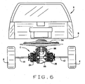
- an automotive vehicle A ( Fig. 1 ) has left and right drive wheels 2 and 4, respectively, that are powered through an electric drive axle B.
- the vehicle A has a source 6 of electrical energy, which could be a generator powered by an internal combustion engine or a bank of batteries or even fuel cells.
- the energy source 6 and the drive axle B are mounted on a supporting structure 8, which could be a frame or a unified body, and the supporting structure 8 is in turn supported in part by the wheels 2 and 4.
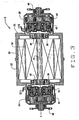
- the drive axle B is coupled to the wheels 2 and 4 through left and right axle shafts 10 and 12. It is organized about an axis X and includes ( Fig. 2 ) a housing 20, an electric motor 22, and left and right torque bias couplings 24 and 26, respectively.
- the motor 22 and couplings 24 and 26 are located within the housing 20.
- the motor 22, which is of the radial flux construction, includes ( Fig. 3 ) a stator 30 which is mounted in the housing 20 in a fixed position around the axis X. It also includes a rotor 32 which is located within the stator 30 where it revolves about the axis X.
- the rotor 32 includes a motor shaft 34 which at its ends is supported in the housing 20 on antifriction bearing 36.
- the housing 20 also encloses the two torque couplings 24 and 26, each of which includes a drive hub 40, a magnetic particle clutch 42, a planetary gear set 44, and a drive flange 46. They too are organized along the axis X.
- the two drive hubs 40 are connected to the motor shaft 34 of the rotor 32 through splines or other devices which enable them to rotate with the shaft 34 and transfer torque from the rotor 32 to their respective torque couplings 24 and 26. Indeed, the two drive hubs 40 rotate in the bearings 36 and support the shaft 34 and likewise the rotor 32 on the bearings 36.
- the drive flanges 46 are for the most part located externally of the housing 20 and serve to couple their respective torque couplings 24 and 26 to the axle shafts 10 and 12.
- the drive hubs 40 function as torque input members, whereas the drive flanges 46 serve as torque output members.
- the clutch 42 for each torque coupling 24 and 26 includes ( Fig. 4 ) an electromagnet 50 and an armature 52. Both are annular in configuration and are organized about the axis X.
- the armature 52 resides within the electromagnet 50, with the two being separated by antifriction bearings to the maintain a uniform annular gap g between them.
- the gap g contains magnetic particles. In the absence of a magnetic field at the gap g, the magnet 50 and armature 52 can rotate, essentially freely with respect to each other. However, when an electrical current is directed through the magnet 50, torque applied to the magnet 50 will transfer to the armature 52. Some slippage between the two may and in most instances will occur.
- the magnet 50 around its periphery carries slip rings 56 which are wiped by brushes 58 fitted to the housing 20.
- the brushes 58 in turn are connected to a source of electrical energy, the potential of which may be varied to vary the current in the electromagnet 50 and the strength of the magnetic field it produces. This controls the torque transferred by the clutch 42.
- the electromagnet 50 of the clutch 42 is secured firmly to the flange of the drive hub 36 at that end of the motor shaft 34 nearest the coupling 24 or 26 of which the clutch 42 is a component.
- the electromagnet 50 rotates with the rotor 32 of the electric motor 32. Should the electromagnet 50 be energized, torque applied to the electromagnet 50 will transfer to the armature 52.
- the planetary set 44 for each torque coupling 24 and 26 includes ( Fig. 4 ) a sun gear 64, a ring gear 66, and planet gears 68 located between and engaged with the sun and ring gears 64 and 66.
- a carrier 70 which establishes the axes about which the planet .gears 68 rotate.
- the sun gear 64 lies along the axis X, its axis coinciding with the axis X. It is provided with a stub shaft 72 which projects into the armature 52 of the clutch 42, to which it is coupled through mating splines.
- the ring gear 66 is attached to the electromagnet 50 of the clutch 42 and to the flange on the drive hub 40 at the end of the motor shaft 34, so that the hub 36, the electromagnet 50, and the ring gear 66 rotate in unison about the axis X and at the same angular velocity.
- the carrier 70 has pins 74 which project into the planet gears 68, so that the planet gears 68, when they rotate, revolve about the pins 74. The pins 74 thus establish the axes of rotation for the planet gears 68.
- the carrier 70 has a spindle 76 which projects through the end of the housing 20 and there is fitted with the drive flange 46.
- the left axle shaft 10 is connected through a universal joint to the drive flange 46 for the left torque coupling 24, whereas the right axle shaft 12 is connected through another universal joint to the drive flange 46 of the right torque coupling 26.
- the motor 22 drives the two axle shafts 10 and 12 through their respective torque couplings 24 and 26.
- the magnetic particle clutches 24 and 26 control the distribution of torque to the two axle shafts 10 and 12.
- the electrical energy source 6 produces an electrical current which powers the motor 22, causing the rotor 32 and motor shaft 34 of the motor 22 to rotate about the axis X.
- the motor shaft 34 delivers the torque to the two torque couplings 24 and 26.
- torque from the motor 22 is applied through the hub 40 at that coupling 24 or 26 to the electromagnet 50 of the clutch 42 and to the ring gear 66 of the planetary set 44 simultaneously.
- the torque splits Some of it passes from the ring gear 66 through the planetary gears 68 to the carrier 70 and thence to the drive flange 46 through the spindle 76.
- the remainder of the torque passes through the gap g to the armature 52 of the clutch 42.
- the armature 52 rotates and transfers the component of the torque passing through the clutch 42 to the sun gear 64 of the planetary set 44, inasmuch as the armature 52 and sun gear 64 are coupled through the stub shaft 72 of the latter.
- the sun gear 64 transfers the torque to the planet gears 68 where it combines with the torque transferred from the ring gear 66, so that the carrier 70 and the drive flange 78 see essentially the full torque applied at the hub 40.
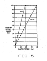
- the torque flows through each torque coupling 24 and 26 in two paths - a mechanical path, including the ring gear 68, planet gears 68 and carrier 70, and a clutch path, including the electromagnet 50 and armature 52 of the clutch 42, and the sun gear 64, planet gears 68 and carrier 70, of the planetary set 44.
- Most of the torque transfers through the mechanical path, with the apportionment between the two paths depending on the gear ratio U between ring gear 66 and the sun gear 64. The higher the ratio, the less the amount of torque transferred through the clutch path.
- the relationship between the torque in the two paths may be expressed with a plot on Cartesian coordinates ( Fig. 5 ).
- the arrangement is such that a small change in torque transferred through the clutch 42 results in a much greater change in torque transmitted through the coupling 24 or 26 of which the clutch 42 is a component, and the torque transmitted through the clutch 42 is dependent on the magnitude of the current passing through the electromagnet 50 of the clutch 42.
- the torque varies almost linearly with the current passing through the electromagnet 50.
- the torque can be divided between the two drive wheels 2 and 4 to best accommodate the driving conditions under which the vehicle A operates. For example, if the vehicle A negotiates a left turn, particularly at higher speeds, more torque should be delivered the right drive wheel 2 than to the left drive wheel 4.
- the clutches 42 in the two torque couplings 24 and 26 are adjusted accordingly.
- the vehicle A may be provided with accelerometers for determining lateral and longitudinal accelerations and yaw, and hence the severity of turns negotiated, as well as speed sensors for determining the velocities of the two axle shafts 10 and 12, preferably from the antilock braking system for the wheels 2 and 4.
- More sensors may determine the position of the steering wheel and the temperatures of the clutches 42 and of the wheel service brakes. These sensors produce signals which may be fed to a microprocessor in the vehicle, which microprocessor would determine the best apportionment of torque between the two driving wheels 2 and 4 and control the current in the clutches 42 of the two torque couplings 10 and 12 accordingly.
- a modified electric drive axle C ( Figs. 6 & 7 ) likewise distributes torque between the left and right drive wheels 2 and 4, apportioning it best to respond to the conditions under which the vehicle A operates. It includes ( Fig. 7 ) an axial flux motor 84, a housing 86 in which the two torque couplings 24 and 26 are enclosed, and a right angle drive 88 located within the housing 86 between the motor 84 and the hubs 40 of the torque couplings 24 and 26.
- the motor 84 includes a stator 92 and a rotor 94, as well as a motor shaft 96 in which the rotor 94 is mounted.
- the shaft 96 rotates about an axis Y oriented at a right angle to the axis X.
- the right angle drive 88 includes a pinion shaft 100 which rotates in the housing 86 about the axis X on antifriction bearings 102.
- One end of the shaft 100 is connected to the motor shaft 94, while the other end has a beveled pinion 104 on it.
- the right angle drive 88 has a connecting shaft 106 which extends between the two hubs 40 and rotates about the axis X. Its ends are fitted to the two drive hubs 40 with mating splines, and the hubs 40 rotate in the housing 86 on bearings 36.
- the right angle drive 88 has a beveled spur gear 108 which is fitted securely the hub 36 at the torque coupling 24. The spur gear 108 meshes with the pinion 104.
- the motor 84 when energized, applies torque to and rotates the pinion shaft 100.
- the pinion 104 at the end of the shaft 100 rotates the spur gear 108 which in turn rotates the connecting shaft 106 and the hubs 40 at the end of it.
- the hubs 40 deliver the torque to the torque couplings 24 and 26 which function as they do in the drive axle A.
Landscapes
- Engineering & Computer Science (AREA)
- Chemical & Material Sciences (AREA)
- Combustion & Propulsion (AREA)
- Transportation (AREA)
- Mechanical Engineering (AREA)
- Retarders (AREA)
- Arrangement And Driving Of Transmission Devices (AREA)
- Electric Propulsion And Braking For Vehicles (AREA)
- Arrangement And Mounting Of Devices That Control Transmission Of Motive Force (AREA)
- Control Of Throttle Valves Provided In The Intake System Or In The Exhaust System (AREA)
- Vehicle Body Suspensions (AREA)
- Arrangement Of Transmissions (AREA)
- Arrangement Or Mounting Of Propulsion Units For Vehicles (AREA)
Claims (14)
- Antriebsachse (B) für ein Kraftfahrzeug (A) mit linken und rechten Antriebsrädern (2, 4), wobei die Achse umfasst: einen Elektromotor (22) mit einem Rotor (32) und linke und rechte Drehmomentkoppler (24, 26), wobei jeder Drehmomentkoppler ein von dem Rotor des Elektromotors angetriebenes Eingangsdrehmomentorgan (40) und ein Ausgangsdrehmomentorgan (46) sowie eine Magnetpartikelkupplung (42) und einen zwischen den Eingangs- und Ausgangsorganen (40, 46) angeordneten Planetenradsatz (44) aufweist, so dass von dem Motor erzeugtes und dem Eingangsorgan (40) zugeführtes Drehmoment über die Kupplung (42) und den Planetenradsatz (44) zum Ausgangsorgan (46) übertragen wird, wobei das übertragene Drehmoment durch die Kupplung gesteuert wird und wobei das Ausgangsorgan des linken Drehmomentkopplers mit dem linken Antriebsrad (4) verbindbar ist und das Ausgangsorgan des rechten Drehmomentkopplers mit dem rechten Antriebsrad (2).
- Antriebsachse nach Anspruch 1, wobei jeder Drehmomentkoppler (24, 26) eine Achse (X) aufweist, um die herum seine Kupplung (42) und sein Planetenradsatz (44) angeordnet sind, und wobei der Rotor des Motors sich um eine Achse (X) dreht, die mit den Achsen der Drehmomentkoppler zusammenfällt.
- Antriebsachse nach Anspruch 1, wobei die Kupplung (42) eines jeden Drehmomentkopplers einen Elektromagneten (50) und einen innerhalb des Elektromagneten angeordneten Anker (52) aufweist, wobei der Planetenradsatz (44) ein Sonnenrad (64), ein mit dem Elektromagneten der Kupplung verbundenes, zusammen mit dem Elektromagneten rotierendes Hohlrad (66), zwischen dem Sonnenrad und dem Hohlrad angeordnete Planetenräder (68) und einen Träger (70) mit Stiften, um die die Planetenräder rotieren, aufweist.
- Antriebsachse nach Anspruch 3, wobei das Eingangsdrehmomentorgan mit dem Elektromagneten der Kupplung und dem Hohlrad des Planetenradsatzes verbunden ist, wobei der Anker der Kupplung mit dem Sonnenrad des Planetenradsatzes verbunden ist und wobei der Träger des Planetenradsatzes mit dem Ausgangsdrehmomentorgan verbunden ist.
- Antriebsachse nach Anspruch 1, wobei das Drehmoment zwischen den Drehmomentorganen eines jeden Drehmomentkopplers über einen die Kupplung (42) umgehenden mechanischen Pfad und über einen durch die Kupplung (42) führenden Kupplungspfad übertragen wird.
- Antriebsachse nach Anspruch 5, wobei die zwei Pfade im Planetenradsatz (44) zusammengeführt sind.
- Antriebsachse nach Anspruch 5, wobei der Großteil des Drehmoments durch den mechanischen Pfad geführt ist.
- Antriebsachse nach Anspruch 1, wobei der Motor (22) ein Radialflussmotor ist.
- Antriebsachse (C) nach Anspruch 1 und weiterhin umfassend einen zwischen dem Motor und den Drehmomentkopplern angeordneten Winkeltrieb (88), wobei der Winkeltrieb ein mit dem Rotor des Elektromotors verbundenes und von diesem angetriebenes Kegelrad (104), eine .zwischen den zwei .Drehmomentkopplern (24, 26) angeordnete, mit den Eingangsdrehmomentorganen der Koppler verbundene Verbindungswelle (106) und ein auf der Welle angeordnetes, mit dem Kegelrad kämmendes Stirnrad aufweist.
- Antriebsachse nach Anspruch 9, wobei der Elektromotor (22) ein Axialflusselektromotor ist.
- Kraftfahrzeug (A) mit linken und rechten Antriebsrädern (2, 4) und linken und rechten, mit den linken und rechten Antriebsrädern verbundenen Achswellen (10, 12) zur Übertragung von Drehmoment auf die Antriebsräder, und mit einer verbesserten Antriebsachse (B) zur Erzeugung von Drehmoment und dessen wahlweisen Verteilung auf die Achswellen, wobei die Antriebsachse umfasst: einen Elektromotor (22); einen linken, zwischen dem Motor (22) und der linken Achswelle (10) angeordneten Drehmomentkoppler (24); und einen rechten, zwischen dem Motor (22) und der rechten Achswelle (12) angeordneten Drehmomentkoppler (26); wobei jeder Drehmomentkoppler eine Magnetpartikelkupplung (42) mit einem Elektromagneten (50), einem in dem Elektromagneten angeordneten Anker (52) und zwischen dem Elektromagneten und der Kupplung angeordneten Magnetpartikeln aufweist; wobei jeder Drehmomentkoppler weiterhin einen Planetenradsatz (44) mit einem Sonnenrad (64), einem Hohlrad (66) und einem zwischen den Sonnen- und Hohlrädern angeordneten Planetenrad (68) aufweist, wobei die Kupplungen und die Planetenradsätze der linken und rechten Kupplungen entlang einer gemeinsamen Achse angeordnet sind.
- Kraftfahrzeug nach Anspruch 11, wobei das Hohlrad (66) und der Elektromagnet (50) oder der Anker (52) der Kupplung (42) eines jeden Drehmomentkopplers derart verbunden sind, dass sie gemeinsam mit der gleichen Winkelgeschwindigkeit rotieren.
- Kraftfahrzeug nach Anspruch 12, wobei der Motor (22) mit dem Elektromagneten (50) eines jeden Drehmomentkopplers verbunden ist; und wobei das Sonnenrad (64) mit dem Anker (52) des Drehmomentkopplers verbunden ist.
- Kraftfahrzeug nach einem der Ansprüche 11 bis 13, wobei bei jedem Koppler der Motor (22) mit dem Hohlrad (66) und dem Elektromagneten (50) der Kupplung verbunden ist und diese dreht; wobei der Anker (52) der Kupplung und das Sonnenrad (64) des Planetenradsatzes miteinander verbunden sind; wobei der Planetenradsatz weiterhin einen Träger (70) aufweist, der Achsen bereitstellt, um die die Planetenräder (68) rotieren; und wobei der Träger (70) mit der Achswelle verbunden ist, die von dem Koppler angetrieben wird.
Applications Claiming Priority (2)
| Application Number | Priority Date | Filing Date | Title |
|---|---|---|---|
| US10/999,327 US7410017B2 (en) | 2004-11-30 | 2004-11-30 | Electric drive axle |
| PCT/US2005/043015 WO2006060348A1 (en) | 2004-11-30 | 2005-11-29 | Electric drive axle |
Publications (2)
| Publication Number | Publication Date |
|---|---|
| EP1817197A1 EP1817197A1 (de) | 2007-08-15 |
| EP1817197B1 true EP1817197B1 (de) | 2008-11-05 |
Family
ID=36263723
Family Applications (1)
| Application Number | Title | Priority Date | Filing Date |
|---|---|---|---|
| EP05852344A Expired - Lifetime EP1817197B1 (de) | 2004-11-30 | 2005-11-29 | Elektrische antriebsachse |
Country Status (8)
| Country | Link |
|---|---|
| US (1) | US7410017B2 (de) |
| EP (1) | EP1817197B1 (de) |
| JP (1) | JP2008521707A (de) |
| KR (1) | KR20070085578A (de) |
| CN (1) | CN101076462A (de) |
| AT (1) | ATE413304T1 (de) |
| DE (1) | DE602005010901D1 (de) |
| WO (1) | WO2006060348A1 (de) |
Cited By (1)
| Publication number | Priority date | Publication date | Assignee | Title |
|---|---|---|---|---|
| DE102023125772A1 (de) | 2023-09-22 | 2025-03-27 | Bayerische Motoren Werke Aktiengesellschaft | Elektrische Antriebseinrichtung für ein Fahrzeug sowie Fahrzeug |
Families Citing this family (37)
| Publication number | Priority date | Publication date | Assignee | Title |
|---|---|---|---|---|
| ATE370059T1 (de) * | 2004-09-29 | 2007-09-15 | Nexxtdrive Ltd | Nabe mit einem antrieb mit veränderlicher übersetzung |
| DE102005034278A1 (de) * | 2005-07-22 | 2007-04-12 | Daimlerchrysler Ag | Antriebseinheit für ein Fahrzeug |
| US7845445B2 (en) * | 2007-03-29 | 2010-12-07 | Arvinmeritor Technology, Llc | Electric powertrain system with planetary drive |
| US20090294188A1 (en) * | 2008-06-02 | 2009-12-03 | Monty Cole | Motorized axle for use with environmentally friendly vehicles |
| US8113308B2 (en) * | 2008-07-02 | 2012-02-14 | Illinois Institute Of Technology | Integrated electric motor differential for hybrid electric vehicles |
| SE533000C2 (sv) * | 2008-10-14 | 2010-06-08 | Bae Systems Haegglunds Ab | Navreduktionsväxel för hjulfordon jämte drivlina för sådant fordon samt fleraxligt hjulfordon utrustat med sådan drivlina |
| US20110088957A1 (en) * | 2009-10-21 | 2011-04-21 | Gm Global Technology Operations, Inc. | Axially offset motor |
| KR20120099684A (ko) * | 2009-11-16 | 2012-09-11 | 레미 테크놀러지스 엘엘씨 | 유성 기어 세트를 구비한 전기 모터 |
| FR2953773B1 (fr) * | 2009-12-16 | 2012-04-27 | Michelin Soc Tech | Moyeu motorise comprenant des moyens de couplage et de decouplage. |
| KR100971903B1 (ko) * | 2010-01-15 | 2010-07-22 | (주)에스아이엠 | 동력 분할식 구동장치 |
| US9302655B2 (en) * | 2010-04-30 | 2016-04-05 | Magna Steyr Fahrzeugtechnik Ag & Co Kg | Drivetrain |
| DE102010036884B4 (de) * | 2010-08-06 | 2023-08-10 | Dr. Ing. H.C. F. Porsche Aktiengesellschaft | Antriebssystem und Kraftfahrzeug mit einem derartigen Antriebssystem |
| KR101757317B1 (ko) * | 2011-07-12 | 2017-07-12 | 현대모비스 주식회사 | 인휠 구동장치 |
| US8944950B2 (en) * | 2012-04-18 | 2015-02-03 | GM Global Technology Operations LLC | System and method of differentiating torque between wheels of a vehicle |
| DE102012011573A1 (de) * | 2012-06-13 | 2013-12-19 | Claas Selbstfahrende Erntemaschinen Gmbh | Lenkachse für landwirtschaftliche Fahrzeuge |
| US8858379B2 (en) | 2012-09-21 | 2014-10-14 | Arvinmeritor Technology, Llc | Axle assembly having an electric motor module |
| US9387756B1 (en) | 2013-10-31 | 2016-07-12 | Quanta Products LLC | Vehicle hybrid drive arrangement |
| US9481256B2 (en) | 2014-01-30 | 2016-11-01 | Amp Electric Vehicles Inc. | Onboard generator drive system for electric vehicles |
| EP3386789A1 (de) | 2015-12-07 | 2018-10-17 | Dana Heavy Vehicle Systems Group, LLC | Architekturen für verteilten antriebsstrang für nutzfahrzeuge mit hybridem elektrischem antriebsstrang und achsen mit zweibereichsentkopplung |
| WO2017114423A1 (en) * | 2015-12-31 | 2017-07-06 | Byd Company Limited | Electric drive axle assembly and vehicle having the electric drive axle assembly |
| US11054009B2 (en) | 2016-03-28 | 2021-07-06 | Dana Heavy Vehicle Systems Group, Llc | Single electric motor drive axle with multiple ratios |
| EP3436299B1 (de) | 2016-03-28 | 2020-02-12 | Dana Heavy Vehicle Systems Group, LLC | Elektrische antriebsstrangachsen mit mehrganggetrieben |
| CN105922852A (zh) * | 2016-05-26 | 2016-09-07 | 丁德胜 | 一种前驱车辆的辅助电动后桥 |
| US9657826B1 (en) * | 2016-08-17 | 2017-05-23 | Borgwarner Inc. | Electric motor with coaxial clutch packs that provide differential and torque vectoring |
| CN107320182B (zh) * | 2017-07-31 | 2021-03-30 | 成都博恩思医学机器人有限公司 | 用于手术台车底座的驱动轮组件及手术台车底座 |
| CN108357521A (zh) * | 2018-02-05 | 2018-08-03 | 罗弟容 | 功能手推车 |
| EP3817941B1 (de) * | 2018-07-03 | 2022-06-08 | KA Group AG | Elektrofahrzeugachse |
| US20200062114A1 (en) * | 2018-08-27 | 2020-02-27 | GM Global Technology Operations LLC | Electric motor transaxle with side-to-side torque control |
| US11447006B2 (en) | 2019-10-03 | 2022-09-20 | Toyota Motor Engineering & Manufacturing North America, Inc. | Electric or hybrid electric vehicle having adjustable vertical electric drive motor and method of making and using |
| US11560053B2 (en) * | 2019-10-03 | 2023-01-24 | Toyota Motor Engineering & Manufacturing North America, Inc. | Electric vehicle comprising a vertical electric propulsion motor and method of making and using the same |
| FR3101816B1 (fr) * | 2019-10-11 | 2022-06-17 | Idee Services | Ensemble de transmission de puissance et véhicule comprenant cet ensemble |
| KR102321809B1 (ko) * | 2020-07-28 | 2021-11-03 | 유순기 | 중공축 모터타입 전기자동차용 트랜스엑슬 시스템 |
| CN113708595B (zh) * | 2021-08-27 | 2023-02-14 | 安徽工程大学 | 带扭振主动抑制功能的轮边永磁直驱传动装置及工作方法 |
| KR20230083531A (ko) * | 2021-12-03 | 2023-06-12 | 현대자동차주식회사 | 토크 벡터링 장치의 윤활구조 |
| DE102022200232A1 (de) * | 2022-01-12 | 2023-07-13 | Robert Bosch Gesellschaft mit beschränkter Haftung | Fahrgestell eines Fahrzeugs |
| CN119527026B (zh) * | 2023-08-29 | 2025-11-04 | 比亚迪股份有限公司 | 车辆驱动系统和车辆 |
| DE102024201694A1 (de) | 2024-02-22 | 2025-08-28 | Schaeffler Technologies AG & Co. KG | Kraftfahrzeug mit parallel zur Hochachse ausgerichteten Axialflussmaschine |
Family Cites Families (21)
| Publication number | Priority date | Publication date | Assignee | Title |
|---|---|---|---|---|
| US5279384A (en) | 1988-03-14 | 1994-01-18 | Honda Giken Kogyo Kabushiki Kaisha | Front and rear road wheel drive apparatus for motor vehicle |
| IT1238128B (it) | 1990-02-14 | 1993-07-07 | Brevini Spa | Differenziale perfezionato a ridotto ingombro complessivo |
| US5419406A (en) * | 1991-10-24 | 1995-05-30 | Aisin Aw Co., Ltd. | Drive system for electric car |
| US5718300A (en) * | 1995-05-15 | 1998-02-17 | New Venture Gear, Inc. | Electric vehicle final drive |
| SE504642C2 (sv) * | 1995-07-14 | 1997-03-24 | Ipumatic Ab | Anordning för att överföra moment mellan två roterbara axlar |
| DE19623738C2 (de) * | 1996-06-14 | 1998-08-06 | Deere & Co | Fahrzeug mit Elektroantrieb |
| US6276474B1 (en) * | 1997-02-18 | 2001-08-21 | Rockwell Heavy Vehicle Systems, Inc. | Low floor drive unit assembly for an electrically driven vehicle |
| US5845546A (en) * | 1997-04-04 | 1998-12-08 | Borg-Warner Automotive, Inc. | Multiple chamber twin clutch axle |
| US5884738A (en) * | 1997-04-30 | 1999-03-23 | Borg-Warner Automotive, Inc. | Clutch assembly having reaction force circuit |
| IT1309008B1 (it) * | 1999-02-24 | 2002-01-15 | Vf Venieri S P A | Gruppo di propulsione per veicoli elettrici a quattro ruote motriciper movimento terra e agricoltura |
| JP4460145B2 (ja) * | 2000-08-30 | 2010-05-12 | 本田技研工業株式会社 | 電気自動車におけるインホイール変速機の制御装置 |
| US6401850B1 (en) | 2001-03-14 | 2002-06-11 | New Venture Gear, Inc. | Electric drive axle for hybrid vehicle |
| US6484834B2 (en) | 2001-03-14 | 2002-11-26 | New Venture Gear, Inc. | Electric drive motor axle with integrated reduction and differential gearset |
| WO2003035422A1 (en) * | 2001-10-23 | 2003-05-01 | The Timken Company | Output power split hybrid electric drive system |
| US6712730B2 (en) * | 2001-12-06 | 2004-03-30 | The Timken Company | Active torque bias coupling |
| US6712728B2 (en) * | 2002-01-29 | 2004-03-30 | The Timken Company | Transfer case with enhanced torque bias capability |
| US6755762B2 (en) * | 2002-03-25 | 2004-06-29 | The Timken Company | Axle center with active torque bias control |
| DE10219921B4 (de) | 2002-05-03 | 2013-03-28 | Zf Friedrichshafen Ag | Antriebsachse für elektromotorisch angetriebene Fahrzeuge |
| DE10316862A1 (de) * | 2003-04-11 | 2004-10-21 | Deere & Company, Moline | Antriebssystem für Fahrzeuge |
| US20040222030A1 (en) | 2003-05-09 | 2004-11-11 | Visteon Global Technologies, Inc. | Vehicle rear suspension support assembly with integrated electric drive |
| US6958030B2 (en) * | 2003-09-29 | 2005-10-25 | American Axle & Manufacturing, Inc. | Electromagnetic locking differential assembly |
-
2004
- 2004-11-30 US US10/999,327 patent/US7410017B2/en not_active Expired - Fee Related
-
2005
- 2005-11-29 WO PCT/US2005/043015 patent/WO2006060348A1/en not_active Ceased
- 2005-11-29 CN CNA2005800425797A patent/CN101076462A/zh active Pending
- 2005-11-29 DE DE602005010901T patent/DE602005010901D1/de not_active Expired - Fee Related
- 2005-11-29 KR KR1020077012225A patent/KR20070085578A/ko not_active Withdrawn
- 2005-11-29 JP JP2007544425A patent/JP2008521707A/ja active Pending
- 2005-11-29 EP EP05852344A patent/EP1817197B1/de not_active Expired - Lifetime
- 2005-11-29 AT AT05852344T patent/ATE413304T1/de not_active IP Right Cessation
Cited By (1)
| Publication number | Priority date | Publication date | Assignee | Title |
|---|---|---|---|---|
| DE102023125772A1 (de) | 2023-09-22 | 2025-03-27 | Bayerische Motoren Werke Aktiengesellschaft | Elektrische Antriebseinrichtung für ein Fahrzeug sowie Fahrzeug |
Also Published As
| Publication number | Publication date |
|---|---|
| CN101076462A (zh) | 2007-11-21 |
| US7410017B2 (en) | 2008-08-12 |
| ATE413304T1 (de) | 2008-11-15 |
| WO2006060348A1 (en) | 2006-06-08 |
| EP1817197A1 (de) | 2007-08-15 |
| JP2008521707A (ja) | 2008-06-26 |
| DE602005010901D1 (de) | 2008-12-18 |
| KR20070085578A (ko) | 2007-08-27 |
| US20060116233A1 (en) | 2006-06-01 |
Similar Documents
| Publication | Publication Date | Title |
|---|---|---|
| EP1817197B1 (de) | Elektrische antriebsachse | |
| US8960341B2 (en) | Continuously variable electric drive module for electric vehicles | |
| JP3993050B2 (ja) | ドライブユニット及び該ユニットを備えた自動車 | |
| US7238140B2 (en) | Differential with torque vectoring capabilities | |
| CN1966334B (zh) | 车轴间转矩产生装置 | |
| US20060025267A1 (en) | Differential with torque vectoring capabilities | |
| US9657826B1 (en) | Electric motor with coaxial clutch packs that provide differential and torque vectoring | |
| US6712730B2 (en) | Active torque bias coupling | |
| CN101557959A (zh) | 差动传动装置 | |
| WO2009086135A4 (en) | Kinetic energy recovery and electric drive for vehicles | |
| JP2003080962A (ja) | 電動モータ用動力伝達装置及びその組み付け方法 | |
| US6755762B2 (en) | Axle center with active torque bias control | |
| CN111152650A (zh) | 具有扭矩矢量控制的混合动力车桥驱动 | |
| EP1470015B1 (de) | Verteilergetriebe mit verbessertem drehmoment- aufteilungsvermögen | |
| JP4891241B2 (ja) | 可変トルク分配装置 | |
| EP1621800A2 (de) | Differentialgetriebe mit Momententeilfunktion | |
| CN117621790A (zh) | 用于机动车辆的驱动设备以及机动车辆 | |
| JPH11315905A (ja) | デファレンシャル装置 | |
| US20080230296A1 (en) | Front to Rear Torque Vectoring Axle with Overspaced Capability for Vehicle Dynamic Control Systems | |
| EP4238802B1 (de) | Verbessertes drehmomentverteilungssystem zwischen achsen eines schwerlastfahrzeugs | |
| US20250269719A1 (en) | Powertrain for an electric vehicle | |
| US20240360889A1 (en) | Transmission and Drive Train for a Motor Vehicle | |
| JP4031144B2 (ja) | カップリング | |
| JP2004197860A (ja) | カップリング | |
| JP2001130283A (ja) | デファレンシャル装置 |
Legal Events
| Date | Code | Title | Description |
|---|---|---|---|
| PUAI | Public reference made under article 153(3) epc to a published international application that has entered the european phase |
Free format text: ORIGINAL CODE: 0009012 |
|
| 17P | Request for examination filed |
Effective date: 20070605 |
|
| AK | Designated contracting states |
Kind code of ref document: A1 Designated state(s): AT BE BG CH CY CZ DE DK EE ES FI FR GB GR HU IE IS IT LI LT LU LV MC NL PL PT RO SE SI SK TR |
|
| 17Q | First examination report despatched |
Effective date: 20071004 |
|
| DAX | Request for extension of the european patent (deleted) | ||
| GRAP | Despatch of communication of intention to grant a patent |
Free format text: ORIGINAL CODE: EPIDOSNIGR1 |
|
| GRAS | Grant fee paid |
Free format text: ORIGINAL CODE: EPIDOSNIGR3 |
|
| GRAA | (expected) grant |
Free format text: ORIGINAL CODE: 0009210 |
|
| AK | Designated contracting states |
Kind code of ref document: B1 Designated state(s): AT BE BG CH CY CZ DE DK EE ES FI FR GB GR HU IE IS IT LI LT LU LV MC NL PL PT RO SE SI SK TR |
|
| REG | Reference to a national code |
Ref country code: GB Ref legal event code: FG4D |
|
| REG | Reference to a national code |
Ref country code: CH Ref legal event code: EP |
|
| REG | Reference to a national code |
Ref country code: IE Ref legal event code: FG4D |
|
| REF | Corresponds to: |
Ref document number: 602005010901 Country of ref document: DE Date of ref document: 20081218 Kind code of ref document: P |
|
| NLV1 | Nl: lapsed or annulled due to failure to fulfill the requirements of art. 29p and 29m of the patents act | ||
| LTIE | Lt: invalidation of european patent or patent extension |
Effective date: 20081105 |
|
| PG25 | Lapsed in a contracting state [announced via postgrant information from national office to epo] |
Ref country code: LT Free format text: LAPSE BECAUSE OF FAILURE TO SUBMIT A TRANSLATION OF THE DESCRIPTION OR TO PAY THE FEE WITHIN THE PRESCRIBED TIME-LIMIT Effective date: 20081105 Ref country code: ES Free format text: LAPSE BECAUSE OF FAILURE TO SUBMIT A TRANSLATION OF THE DESCRIPTION OR TO PAY THE FEE WITHIN THE PRESCRIBED TIME-LIMIT Effective date: 20090216 Ref country code: AT Free format text: LAPSE BECAUSE OF FAILURE TO SUBMIT A TRANSLATION OF THE DESCRIPTION OR TO PAY THE FEE WITHIN THE PRESCRIBED TIME-LIMIT Effective date: 20081105 |
|
| PG25 | Lapsed in a contracting state [announced via postgrant information from national office to epo] |
Ref country code: IS Free format text: LAPSE BECAUSE OF FAILURE TO SUBMIT A TRANSLATION OF THE DESCRIPTION OR TO PAY THE FEE WITHIN THE PRESCRIBED TIME-LIMIT Effective date: 20090305 Ref country code: FI Free format text: LAPSE BECAUSE OF FAILURE TO SUBMIT A TRANSLATION OF THE DESCRIPTION OR TO PAY THE FEE WITHIN THE PRESCRIBED TIME-LIMIT Effective date: 20081105 Ref country code: NL Free format text: LAPSE BECAUSE OF FAILURE TO SUBMIT A TRANSLATION OF THE DESCRIPTION OR TO PAY THE FEE WITHIN THE PRESCRIBED TIME-LIMIT Effective date: 20081105 Ref country code: SI Free format text: LAPSE BECAUSE OF FAILURE TO SUBMIT A TRANSLATION OF THE DESCRIPTION OR TO PAY THE FEE WITHIN THE PRESCRIBED TIME-LIMIT Effective date: 20081105 Ref country code: LV Free format text: LAPSE BECAUSE OF FAILURE TO SUBMIT A TRANSLATION OF THE DESCRIPTION OR TO PAY THE FEE WITHIN THE PRESCRIBED TIME-LIMIT Effective date: 20081105 Ref country code: PL Free format text: LAPSE BECAUSE OF FAILURE TO SUBMIT A TRANSLATION OF THE DESCRIPTION OR TO PAY THE FEE WITHIN THE PRESCRIBED TIME-LIMIT Effective date: 20081105 |
|
| PG25 | Lapsed in a contracting state [announced via postgrant information from national office to epo] |
Ref country code: MC Free format text: LAPSE BECAUSE OF NON-PAYMENT OF DUE FEES Effective date: 20081130 |
|
| PG25 | Lapsed in a contracting state [announced via postgrant information from national office to epo] |
Ref country code: RO Free format text: LAPSE BECAUSE OF FAILURE TO SUBMIT A TRANSLATION OF THE DESCRIPTION OR TO PAY THE FEE WITHIN THE PRESCRIBED TIME-LIMIT Effective date: 20081105 Ref country code: EE Free format text: LAPSE BECAUSE OF FAILURE TO SUBMIT A TRANSLATION OF THE DESCRIPTION OR TO PAY THE FEE WITHIN THE PRESCRIBED TIME-LIMIT Effective date: 20081105 Ref country code: DK Free format text: LAPSE BECAUSE OF FAILURE TO SUBMIT A TRANSLATION OF THE DESCRIPTION OR TO PAY THE FEE WITHIN THE PRESCRIBED TIME-LIMIT Effective date: 20081105 Ref country code: BG Free format text: LAPSE BECAUSE OF FAILURE TO SUBMIT A TRANSLATION OF THE DESCRIPTION OR TO PAY THE FEE WITHIN THE PRESCRIBED TIME-LIMIT Effective date: 20090205 Ref country code: BE Free format text: LAPSE BECAUSE OF FAILURE TO SUBMIT A TRANSLATION OF THE DESCRIPTION OR TO PAY THE FEE WITHIN THE PRESCRIBED TIME-LIMIT Effective date: 20081105 |
|
| REG | Reference to a national code |
Ref country code: IE Ref legal event code: MM4A |
|
| PG25 | Lapsed in a contracting state [announced via postgrant information from national office to epo] |
Ref country code: SE Free format text: LAPSE BECAUSE OF FAILURE TO SUBMIT A TRANSLATION OF THE DESCRIPTION OR TO PAY THE FEE WITHIN THE PRESCRIBED TIME-LIMIT Effective date: 20090205 Ref country code: CZ Free format text: LAPSE BECAUSE OF FAILURE TO SUBMIT A TRANSLATION OF THE DESCRIPTION OR TO PAY THE FEE WITHIN THE PRESCRIBED TIME-LIMIT Effective date: 20081105 Ref country code: PT Free format text: LAPSE BECAUSE OF FAILURE TO SUBMIT A TRANSLATION OF THE DESCRIPTION OR TO PAY THE FEE WITHIN THE PRESCRIBED TIME-LIMIT Effective date: 20090406 |
|
| PLBE | No opposition filed within time limit |
Free format text: ORIGINAL CODE: 0009261 |
|
| STAA | Information on the status of an ep patent application or granted ep patent |
Free format text: STATUS: NO OPPOSITION FILED WITHIN TIME LIMIT |
|
| PG25 | Lapsed in a contracting state [announced via postgrant information from national office to epo] |
Ref country code: SK Free format text: LAPSE BECAUSE OF FAILURE TO SUBMIT A TRANSLATION OF THE DESCRIPTION OR TO PAY THE FEE WITHIN THE PRESCRIBED TIME-LIMIT Effective date: 20081105 |
|
| 26N | No opposition filed |
Effective date: 20090806 |
|
| PG25 | Lapsed in a contracting state [announced via postgrant information from national office to epo] |
Ref country code: DE Free format text: LAPSE BECAUSE OF NON-PAYMENT OF DUE FEES Effective date: 20090603 Ref country code: IE Free format text: LAPSE BECAUSE OF NON-PAYMENT OF DUE FEES Effective date: 20081129 |
|
| REG | Reference to a national code |
Ref country code: CH Ref legal event code: PL |
|
| GBPC | Gb: european patent ceased through non-payment of renewal fee |
Effective date: 20091129 |
|
| PG25 | Lapsed in a contracting state [announced via postgrant information from national office to epo] |
Ref country code: LU Free format text: LAPSE BECAUSE OF NON-PAYMENT OF DUE FEES Effective date: 20081129 Ref country code: HU Free format text: LAPSE BECAUSE OF FAILURE TO SUBMIT A TRANSLATION OF THE DESCRIPTION OR TO PAY THE FEE WITHIN THE PRESCRIBED TIME-LIMIT Effective date: 20090506 Ref country code: CY Free format text: LAPSE BECAUSE OF FAILURE TO SUBMIT A TRANSLATION OF THE DESCRIPTION OR TO PAY THE FEE WITHIN THE PRESCRIBED TIME-LIMIT Effective date: 20081105 |
|
| PG25 | Lapsed in a contracting state [announced via postgrant information from national office to epo] |
Ref country code: TR Free format text: LAPSE BECAUSE OF FAILURE TO SUBMIT A TRANSLATION OF THE DESCRIPTION OR TO PAY THE FEE WITHIN THE PRESCRIBED TIME-LIMIT Effective date: 20081105 |
|
| PG25 | Lapsed in a contracting state [announced via postgrant information from national office to epo] |
Ref country code: CH Free format text: LAPSE BECAUSE OF NON-PAYMENT OF DUE FEES Effective date: 20091130 Ref country code: LI Free format text: LAPSE BECAUSE OF NON-PAYMENT OF DUE FEES Effective date: 20091130 Ref country code: GR Free format text: LAPSE BECAUSE OF FAILURE TO SUBMIT A TRANSLATION OF THE DESCRIPTION OR TO PAY THE FEE WITHIN THE PRESCRIBED TIME-LIMIT Effective date: 20090206 |
|
| PG25 | Lapsed in a contracting state [announced via postgrant information from national office to epo] |
Ref country code: GB Free format text: LAPSE BECAUSE OF NON-PAYMENT OF DUE FEES Effective date: 20091129 |
|
| REG | Reference to a national code |
Ref country code: FR Ref legal event code: ST Effective date: 20111209 |
|
| PG25 | Lapsed in a contracting state [announced via postgrant information from national office to epo] |
Ref country code: FR Free format text: LAPSE BECAUSE OF NON-PAYMENT OF DUE FEES Effective date: 20090105 |
|
| PG25 | Lapsed in a contracting state [announced via postgrant information from national office to epo] |
Ref country code: IT Free format text: LAPSE BECAUSE OF FAILURE TO SUBMIT A TRANSLATION OF THE DESCRIPTION OR TO PAY THE FEE WITHIN THE PRESCRIBED TIME-LIMIT Effective date: 20081105 |