EP1816716A2 - Abmantelwerkzeug - Google Patents
Abmantelwerkzeug Download PDFInfo
- Publication number
- EP1816716A2 EP1816716A2 EP06126254A EP06126254A EP1816716A2 EP 1816716 A2 EP1816716 A2 EP 1816716A2 EP 06126254 A EP06126254 A EP 06126254A EP 06126254 A EP06126254 A EP 06126254A EP 1816716 A2 EP1816716 A2 EP 1816716A2
- Authority
- EP
- European Patent Office
- Prior art keywords
- abmantelwerkzeug
- knife holder
- cutting blade
- recesses
- flat cable
- Prior art date
- Legal status (The legal status is an assumption and is not a legal conclusion. Google has not performed a legal analysis and makes no representation as to the accuracy of the status listed.)
- Granted
Links
- 239000004020 conductor Substances 0.000 claims description 21
- 239000011796 hollow space material Substances 0.000 abstract 1
- 238000009413 insulation Methods 0.000 description 3
- 238000007654 immersion Methods 0.000 description 2
- 230000001154 acute effect Effects 0.000 description 1
- 238000006073 displacement reaction Methods 0.000 description 1
- 238000010616 electrical installation Methods 0.000 description 1
- 230000003014 reinforcing effect Effects 0.000 description 1
Images







Classifications
-
- H—ELECTRICITY
- H02—GENERATION; CONVERSION OR DISTRIBUTION OF ELECTRIC POWER
- H02G—INSTALLATION OF ELECTRIC CABLES OR LINES, OR OF COMBINED OPTICAL AND ELECTRIC CABLES OR LINES
- H02G1/00—Methods or apparatus specially adapted for installing, maintaining, repairing or dismantling electric cables or lines
- H02G1/12—Methods or apparatus specially adapted for installing, maintaining, repairing or dismantling electric cables or lines for removing insulation or armouring from cables, e.g. from the end thereof
- H02G1/1295—Devices for splitting and dismantling flat cables
-
- H—ELECTRICITY
- H02—GENERATION; CONVERSION OR DISTRIBUTION OF ELECTRIC POWER
- H02G—INSTALLATION OF ELECTRIC CABLES OR LINES, OR OF COMBINED OPTICAL AND ELECTRIC CABLES OR LINES
- H02G1/00—Methods or apparatus specially adapted for installing, maintaining, repairing or dismantling electric cables or lines
- H02G1/12—Methods or apparatus specially adapted for installing, maintaining, repairing or dismantling electric cables or lines for removing insulation or armouring from cables, e.g. from the end thereof
- H02G1/1202—Methods or apparatus specially adapted for installing, maintaining, repairing or dismantling electric cables or lines for removing insulation or armouring from cables, e.g. from the end thereof by cutting and withdrawing insulation
- H02G1/1204—Hand-held tools
- H02G1/1229—Hand-held tools the cutting element making a longitudinal, and a transverse or a helical cut
Definitions
- the invention relates to a Abmanteltechnikmaschine for a flat cable, which consists of a plurality of conductors and a conductor enveloping the jacket.
- a flat cable usually has a plurality of conductors, each having at least one conductor wire, a surrounding insulation and a conductor embedding the conductor together with their insulation jacket.
- the invention has for its object to provide a Abmantelwerkmaschine, with the removal of a certain portion of the shell is facilitated especially on an already installed flat cable. In addition, it should be ensured that the jacket is indeed completely cut through, but that the sheaths of the conductors are not damaged.
- the stripping tool thus offers not only the knife function per se but also a kind of template function for cuts to be carried out.
- the knife holder is designed so that by means of the cutting blade of the jacket is severed clean, so that the relevant section of the shell can be deducted without rework or additional tearing of the ladder usually. Since it also serves as a guide for the knife holder in some of the cuts, exact cuts are ensured.
- the Abmantelwerkmaschine can be stored to save space when not in use, it is provided that the inner contours of the clamped jaws define a cavity into which the knife holder can be introduced and in which it is stored.
- the knife holder is guided not only in the cutting direction through the grooves, but also in terms of immersion depth of the cutting blade in the jacket, it is provided that the grooves of recesses are surrounded with respect to the grooves larger dimensions, so that the edges adjacent the grooves bearing surfaces for the Form knife holder. This prevents that the sheaths of the conductors are cut.
- the recesses are provided on the outer, facing away from each other sides of the jaws.
- the blade holder can always be arranged exactly opposite the clamping jaw, it is provided that the blade holder has a guide projection in which the cutting blade having end portion, so that the surfaces formed thereby abut against the edges bounding the groove.
- the guide approach is designed so that it can be moved within the groove closing.
- the sliding element is used according to a variant in a holding tube, which is equipped with an annular groove, into which a securing bolt engages for axial securing. Further, in the holding tube, a spirally extending groove is provided, in which engages a pin which penetrates holes of the sliding element and the cutting blade.
- the holding tube can be rotated without tools and without much effort is provided that on the blade opposite the end of a handle is fixed.
- This handle is in a preferred embodiment, a knob which projects from the end face of the knife holder.
- This locking screw is a threaded pin in a preferred embodiment. To twist the threaded bolt, the locking screw must first be solved.
- the jaws are U-shaped in cross-section, wherein the lateral edges have recesses which extend from a front end towards the opposite end, but at a distance to this end. As a result, a pocket is formed in which the flat hose to be processed can be inserted.
- the recesses are chosen so that the flat hose clamped for processing can be. Since the recesses terminate at a distance from the previous front end of the clamping element, a stop is formed, against which the longitudinal edge of the flat tube, so that it is always positioned exactly.
- the recesses limiting edges of the jaws may be equipped with protruding teeth that dig into the jacket, so that mutatis mutandis the flat tube is fixed positively.
- the knife holder While the grooves of the clamping jaws form the guide for the knife holder when performing the cuts transversely to the conductors of the flat cable, the knife holder is introduced into the cavity defined by the opposing clamping jaws for producing a longitudinal cut. The same applies to the completion of the cross sections around the side regions of the flat cable.
- the Abmantelwerkmaschine invention is realized as a hand-held tool from only a few items, so that it is inexpensive to produce. It allows such a fast and unproblematic stripping of a ribbon cable, as one would expect only from a much more complicated built-up tool.
- the stripping tool shown in FIGS. 1 to 11 consists of two functional units, namely a clamping element 2, which has two clamping jaws 3, 4, and a knife holder 5 or a knife holder into which a cutting blade 6, which is described in more detail, is inserted.
- a jacket 31 of a flat cable 29 is removable.
- the cutting blade 6 passes through a slot 7 of the knife holder 5, which is formed by the two parts of the cutting blade 6 receiving sliding element 18, which will be explained with reference to FIG 11.
- the two jaws 3, 4 are connected to the tip of the cutting blade 6 associated Stirnend Scheme in a manner not shown clamp-like articulated together, so that the two jaws 3, 4 can be pivoted into a position at an acute angle to each other standing position.
- the clamping element 2 formed essentially by the two clamping jaws 3, 4 is at the end area assigned to the cutting blade 6 each with two differently contoured shaped - rounded here - recesses 9, 10, which serve to guide the Abmanteltechnikmaschinees 1 when a section around the rounded side portions (Fig. 13d) or in the longitudinal direction (Fig. 13e) of the flat cable 30 is performed.
- FIG 2 shows that the tip of the cutting blade 6 protrudes from the bottom of the recesses 9, 10, so that immersion in the sheath of the flat cable is possible.
- Figure 2 also shows that the recesses 9, 10 are limited at their free ends of tips 32, which are available for breaking the cable tube, in particular, even if smaller residues have not been severed.
- FIG. 3 shows that the knife holder 5 is equipped on the side opposite the cutting blade 6 with a rotatable handle in the form of a rotary knob 11.
- This knob 11 can be rotated in both directions and communicates with the cutting blade 6 in a fixed connection, so that by rotation of the knob 11, the cutting blade 6 further moved out of the knife holder 5 or can be retracted further, as explained in more detail with reference to FIG 11 becomes.
- the direction in which the knob 11 is to move is determined by the two symbols "plus” and "minus".
- the two jaws 3, 4 are provided with longitudinally extending grooves 12, 13 which serve as guides for the knife holder 5 when cuts are made transversely to the conductors of the flat cable in the jacket as will be explained with reference to FIGS. 8 and 9.
- the grooves 12 and 13 are in recesses 14, 15 which extend from outside to inside.
- bearing surfaces 16, 17 are formed for the blade holder 5 inserted into the grooves 12, 13.
- the knife holder 5 is positioned exactly opposite the clamping element 2.
- These recesses are therefore provided on the opposite sides of the jaws 3, 4.
- FIG. 11 shows, the cutting blade 6 is fixed in a two-part sliding element 18.
- This sliding element 18 is arranged in a holding tube 19 integrally formed with the rotary head 11.
- This holding tube 19 is provided with an annular groove 20 which is disposed adjacent to the rotary knob 11. In this annular groove 20 engages a locking pin 21, which is firmly inserted into the knife holder 5. As a result, the holding tube 19 is secured against displacement in the longitudinal direction.
- the holding tube 19 is also provided with a helically extending groove 22, in which a bolt 23 engages. This bolt is also guided through holes 24, 25 of the sliding element 18. As a result, the two parts of the sliding element 18 are held. It is apparent from Figure 11, that upon rotation of the holding tube 19 by the rotary handle 11, the sliding member 18 moves with the cutting blade 16 in the longitudinal direction, while the rotary tube 19 does not move in the axial direction.
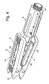
- FIG. 4 shows the partially removed from the clamping element 2 knife holder 5. It is apparent from this figure that the two jaws 3, 4 are designed in cross-section U-shaped, and that the side edges are recessed to form a receiving pocket for a flat cable. To secure the flat cable, the edges bounding the recess are provided with teeth 26 which cut into the jacket of the flat cable.
- FIG. 5 shows that the knife holder 5 is provided with a securing screw 27 which prevents a twisting of the holding tube 19. In order to change the position of the cutting blade 6, this locking screw 27 must first be solved.
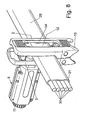
- FIG. 7 shows the clamping element 2 shown in FIG. 4 in an enlarged view. From this, in particular, the U-shaped cross-section of the two jaws 3, 4 shows. In addition, this figure shows that the jaws are stabilized by reinforcing triangles 28.
- Figures 8 and 9 show that the clamping element 2 can be placed on a flat cable 29.
- the flat cable 29 is provided with the jacket 31, which is to be removed over a predetermined range.
- the knife holder 5 according to the figures 8 and 9 (see also Fig. 13b, c) is inserted into the grooves 12, 13.
- the knife holder 5 can be converted from the position shown in FIGS. 8 and 13b into the position shown in FIGS. 9 and 13d.
- the clamping element 2 is offset on the flat cable, so that then the other two sections can be introduced.
- Figure 9 shows that the respective groove 12, 13 forms a guide for the knife holder 5.
- the knife holder is provided in the region of the cutting blade 6 with a lug.
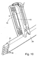
- FIGS. 10 and 13d indicate how the cross sections are easily and quickly extended around the sides of the flat cable.
- the two recesses 10 lead with a slightly larger radius the blade holder 5 to the side regions of the flat cable. Thus, two complete 360 ° cuts are realized on the flat cable.
- FIG. 13e shows how then a cut takes place in the longitudinal direction of the flat cable 29, which connects the two cross sections.
- the two other, almost V-shaped recesses 10 the flat cable safely on its side in the longitudinal direction of the flat cable 29th
- the flat cable 29 is held by means of the clamping element 2, and that the two jaws 3, 4 of the clamping element 2 form a guide for the knife holder 5.
- the two jaws 3, 4 are provided with grooves 12, 13, is guided by the transverse to the conductors 30 of the flat cable 29 of the knife holder 5 to form sections.
- the recesses 9, 10 respectively form guides and cut depths at the edge cuts around the edges and along the cable.
Landscapes
- Removal Of Insulation Or Armoring From Wires Or Cables (AREA)
- Installation Of Indoor Wiring (AREA)
- Knives (AREA)
Abstract
Description
- Die Erfindung bezieht sich auf ein Abmantelwerkzeug für ein Flachkabel, welches aus mehreren Leitern und einem die Leiter umhüllenden Mantel besteht.
- Ein Flachkabel weist in der Regel mehrere Leiter auf, die jeweils wenigstens eine Leitungsader, eine diese umgebenden Isolierung und einen die Leiter nebst deren Isolierung einbettenden Mantel aufweisen.
- Bei der Erstellung einer Elektroinstallation kann es erforderlich werden, daß der äußere Mantel über einen bestimmten Abschnitt des Flachkabels entfernt wird, um beispielsweise eine Abzweigung herzustellen. Zum Entfernen dieses Abschnittes des Mantels wird ein Messer verwendet, um den Mantel mit zwei beabstandeten und quer zu den Leitern umlaufenden Schnitten zu versehen. Diese Arbeitsweise ist recht umständlich und auch zeitraubend. Ein weiterer Nachteil ist noch darin zu sehen, daß die Leiter oder deren Isolierungen relativ leicht beschädigt werden. Besonders schwierig ist zudem das Entfernen des Mantels zur Erstellung einer Abzweigung an einem bereits installierten Flachkabel.
- Der Erfindung liegt die Aufgabe zugrunde, ein Abmantelwerkzeug zu schaffen, mit dem das Entfernen eines bestimmten Abschnittes des Mantels insbesondere auch an einem bereits installierten Flachkabel erleichtert wird. Darüber hinaus soll sichergestellt sein, daß der Mantel zwar vollständig durchgeschnitten wird, daß jedoch die Umhüllungen der Leiter nicht beschädigt werden.
- Die Erfindung wird durch den Gegenstand des Anspruchs 1 gelöst.
- Danach weist das Abmantelwerkzeug ein am Flachkabel festsetzbares Klemmelement und einen mit einem Schneidmesser versehenen Messerhalter auf, wobei das Klemmelement als Führung und eine Aufnahme für den Messerhalter ausgebildet ist.
- Das Abmantelwerkzeug bietet damit nicht nur die Messerfunktion an sich sondern auch eine Art Schablonenfunktion für durchzuführende Schnitte.
- Der Messerhalter ist so ausgelegt, daß mittels des Schneidmessers der Mantel sauber durchtrennt wird, so daß der betreffende Abschnitt des Mantels in der Regel ohne Nacharbeit oder ein zusätzliches Einreißen von den Leitern abgezogen werden kann. Da er bei einigen der Schnitte zusätzlich als Führung für den Messerhalter dient, sind exakte Schnitte sichergestellt.
- Eine konstruktiv einfache Ausführung ergibt sich, wenn das Klemmelement klammerartig ausgebildet ist und zwei gelenkig miteinander verbundene Klemmbacken aufweist. Die Klemmbacken werden zum Einlegen des Kabels geöffnet. Durch Federwirkung wird dann das Flachkabel zwischen den beiden Klemmbacken festgesetzt.
- Damit das Abmantelwerkzeug bei Nichtgebrauch platzsparend aufbewahrt werden kann, ist vorgesehen, daß die Innenkonturen der zusammengefahrenen Klemmbacken einen Hohlraum begrenzen, in den der Messerhalter einbringbar und in dem er aufbewahrbar ist.
- Die Handhabung des Abmantelwerkzeugs bei der Durchführung der Schnitte wird besonders günstig, wenn die Klemmbacken miteinander korrespondierende, in den Längsrichtungen der Klemmbacken sich erstreckenden Führungsschlitze aufweisen, in denen der an das Schneidmesser angrenzende Bereich zur Durchführung von Schnitten quer zu den Leitern verfahrbar ist. Sofern stets die gegenüberliegenden Schnitte durch Umsetzen des Messerhalters in den Mantel eingeschnitten werden, ergibt sich, daß die beiden Schnitte versatzfrei zueinander liegen.
- Damit der Messerhalter nicht nur in Schneidrichtung durch die Nuten geführt ist, sondern auch hinsichtlich der Eintauchtiefe des Schneidmessers in den Mantel, ist vorgesehen, daß die Nuten von Ausnehmungen mit gegenüber den Nuten größeren Abmessungen umgeben sind, so daß die an die Nuten angrenzenden Ränder Auflageflächen für den Messerhalter bilden. Dadurch wird verhindert, daß die Umhüllungen der Leiter angeschnitten werden.
- Die Ausnehmungen sind an den äußeren, einander abgewandt liegenden Seiten der Klemmbacken vorgesehen.
- Damit der Messerhalter gegenüber der Klemmbacke stets exakt angeordnet werden kann, ist vorgesehen, daß der Messerhalter in dem das Schneidmesser aufweisenden Endbereich einen Führungsansatz aufweist, so daß die dadurch gebildeten Flächen gegen die die Nut begrenzenden Ränder anschlagen. Der Führungsansatz ist so gestaltet, daß er schließend innerhalb der Nut verfahrbar ist.
- Die Schnittiefe ist bei den zu bearbeitenden Flachkabeln äußerst genau einzustellen. Damit dies in einfachster Weise exakt durchführbar ist, ist vorgesehen, daß der Messerhalter eine Einrichtung zur Einstellung der Schnitttiefe aufweist. Diese kann mit einem das Schneidmesser aufnehmenden Schiebeelement ausgestattet sein.
- Das Schiebeelement ist nach einer Variante in ein Halterohr eingesetzt, welches mit einer Ringnut ausgestattet ist, in die zur axialen Sicherung ein Sicherungsbolzen eingreift. Ferner ist in dem Halterohr eine spiralförmig verlaufende Nut vorgesehen, in die ein Bolzen eingreift, der Bohrungen des Schiebeelementes und des Schneidmessers durchdringt. Damit das Halterohr ohne Werkzeug und ohne großen Kraftaufwand gedreht werden kann ist vorgesehen, daß auf das dem Schneidmesser gegenüberliegende Ende eine Handhabe festgesetzt ist. Diese Handhabe ist in bevorzugter Ausführung ein Drehknopf, der gegenüber der Stirnfläche des Messerhalters vorsteht. Damit sich die Schnittiefe nicht selbsttätig verändert, ist vorgesehen, daß das Halterohr mittels einer Sicherungsschraube gegen Drehung gesichert ist. Diese Sicherungsschraube ist in bevorzugter Ausführung ein Gewindestift. Zur Verdrehung des Gewindebolzens muß die Sicherungsschraube zunächst gelöst werden.
- Die Klemmbacken sind im Querschnitt U-förmig gestaltet, wobei die seitlichen Ränder Aussparungen aufweisen, die sich von einem Stirnende in Richtung zum gegenüberliegenden Stirnende erstrecken, jedoch im Abstand zu diesem enden. Dadurch wird eine Tasche gebildet, in der der zu bearbeitende Flachschlauch eingelegt werden kann. Die Aussparungen sind so gewählt, daß der Flachschlauch zur Bearbeitung festgeklemmt werden kann. Da die Aussparungen im Abstand zu dem vorherigen Stirnende des Klemmelementes enden, wird ein Anschlag gebildet, an den der Längsrand des Flachschlauches anliegt, so daß dieser stets exakt positioniert ist. Die die Aussparungen begrenzenden Ränder der Klemmbacken können mit vorstehenden Zähnen ausgestattet sein, die sich in den Mantel eingraben, so daß sinngemäß der Flachschlauch formschlüssig festgelegt ist.
- Während die Nuten der Klemmbacken bei der Durchführung der Schnitte quer zu den Leitern des Flachkabels die Führung für den Messerhalter bilden, wird zum Herstellen eines Längsschnittes der Messerhalter in den durch die gegenüberliegenden Klemmbacken begrenzten Hohlraum eingebracht. Analoges gilt für die Vervollständigung der Querschnitte um die Seitenbereiche des Flachkabels.
- Damit auch beim Einbringen dieser Schnitte das Klemmelement eine Führung bildet, ist vorgesehen, daß das Klemmelement an der der Tasche zur Klemmung des eingelegten Flachkabels gegenüberliegenden Stirnendbereich eine Mehrzahl von V-förmigen oder halbkreisförmige Ausnehmungen aufweist, in die der Längsrand des Mantels einlegbar ist.
- Das erfindungsgemäße Abmantelwerkzeug ist als Handbedienwerkzeug aus nur wenigen Einzelteilen realisierbar, so dass es günstig herstellbar ist. Es ermöglicht ein so schnelles und unproblematisches Abmanteln eines Flachbandkabels, wie man es nur von einem weit komplizierter aufgebauten Werkzeug erwarten würde.
- Weitere vorteilhafte Ausgestaltungen sind den übrigen Unteransprüchen zu entnehmen.
- Anhand der beiliegenden Zeichnungen wird die Erfindung noch näher erläutert. Es zeigen:
- Figur 1
- das erfindungsgemäße Abmantelwerkzeug in perspektivischer Darstellung in der Außerbetriebsstellung,
- Figur 2
- den Stirnendbereich mit den V-förmigen Ausnehmungen in vergrößerter Darstellung,
- Figur 3
- eine der Figur 1 entsprechende Darstellung, jedoch mit Blick auf das andere Stirnende,
- Figur 4
- eine der Figur 3 entsprechende Darstellung, jedoch mit dem teilweise aus dem Klemmelement herausgenommenen Messerhalter,
- Figur 5
- den Messerhalter als Einzelheit in perspektivischer Darstellung,
- Figur 6
- den mit der Handhabe ausgerüsteten Stirnendbereich des Messerhalters in vergrößerter Darstellung,
- Figur 7
- das Klemmelement als Einzelheit mit geöffneten Klemmbacken,
- Figur 8
- die Abmantelvorrichtung mit in das Klemmelement eingelegtem Flachkabel in der Stellung zur Durchführung von Schnitten quer zu den Leitern,
- Figur 9
- eine der Figur 8 entsprechende Darstellung, jedoch zur Durchführung der Schnitte quer zu den Adern der gegenüberliegenden Seite,
- Figur 10
- das Abmantelwerkzeug in der Stellung zur Durchführung eines Schnittes in Richtung der Leiter des Flachkabels,
- Figur 11
- den Messerhalter in einer sprengbildlichen Darstellung zeigend und
- Figur 12
- ein Flachkabel, bei dem ein Stück des Mantels entfernt ist; und
- Figur 13a-e
- den Messerhalter und fünf aufeinanderfolgende Schritte beim Durchtrennen des Mantels..
- Das in den Figuren 1 bis 11 dargestellte Abmantelwerkzeug besteht aus zwei Funktionseinheiten, nämlich einem Klemmelement 2, welches zwei Klemmbacken 3, 4 aufweist, und einem Messerhalter 5 bzw. einer Messeraufnahme, in den/die ein noch näher beschriebenes Schneidmesser 6 eingesetzt ist.
- Mit dem Werkzeug ist ein Mantel 31 eines Flachkabels 29 entfernbar.
- Das Schneidmesser 6 durchsetzt einen Schlitz 7 des Messerhalters 5, der durch die beiden Teile eines das Schneidmesser 6 aufnehmenden Schiebeelementes 18 gebildet wird, was noch anhand der Figur 11 erläutert wird.
- Die beiden Klemmbacken 3, 4 sind an dem der Spitze des Schneidmessers 6 zugeordneten Stirnendbereich in nicht näher dargestellter Weise klammerartig gelenkig miteinander verbunden, so daß die beiden Klemmbacken 3, 4 in eine unter einem spitzen Winkel zueinander stehende Lage geschwenkt werden können.
- Wie die Figuren 1 und 2 zeigen, ist das im wesentlichen durch die beiden Klemmbacken 3, 4 gebildete Klemmelement 2 an der dem Schneidmesser 6 zugeordneten Endbereich mit jeweils zwei unterschiedlich konturierten geformten - hier abgerundeten - Ausnehmungen 9, 10 versehen, die der Führung des Abmantelwerkzeuges 1 dienen, wenn ein Schnitt um die abgerundeten Seitenbereiche (Fig. 13d) oder in Längsrichtung (Fig. 13e) des Flachkabels 30 durchgeführt wird.
- Die Figur 2 zeigt den die Ausnehmungen 9, 10 aufweisenden Stirnendbereich in vergrößerter Darstellung.
- Figur 2 zeigt, daß die Spitze des Schneidmessers 6 gegenüber dem Grund der Ausnehmungen 9, 10 vorsteht, so daß ein Eintauchen in den Mantel des Flachkabels möglich ist.
- Figur 2 zeigt ferner, daß die Ausnehmungen 9, 10 am ihren freien Enden von Spitzen 32 begrenzt sind, die zum Aufbrechen des Kabelschlauches nutzbar sind, insbesondere auch, wenn noch kleinere Reste nicht durchtrennt worden sind.
- Figur 3 zeigt, daß der Messerhalter 5 an der dem Schneidmesser 6 gegenüberliegenden Seite mit einer drehbaren Handhabe in Form eines Drehknopfes 11 ausgestattet ist. Dieser Drehknopf 11 kann in beiden Richtungen gedreht werden und steht mit dem Schneidmesser 6 in einer festen Verbindung, so daß durch Drehung des Drehknopfes 11 das Schneidmesser 6 weiter aus dem Messerhalter 5 herausgefahren oder weiter eingefahren werden kann, wie anhand der Figur 11 noch näher erläutert wird. In welcher Richtung der Drehknopf 11 zu bewegen ist, wird durch die beiden Symbole "plus" und "minus" bestimmt.
- Wie die Figuren 1, 3, 4 und 5 zeigen, sind die beiden Klemmbacken 3, 4 mit in Längsrichtung verlaufenden Nuten 12, 13 versehen, die als Führung für den Messerhalter 5 dienen, wenn Schnitte quer zu den Leitern des Flachkabels in den Mantel eingebracht werden, wie noch anhand der Figuren 8 und 9 erläutert wird.
- Wie insbesondere die Figuren 1 und 3 zeigen, liegen die Nuten 12 und 13 in Ausnehmungen 14, 15, die sich von außen nach innen erstrecken. Dadurch werden Auflagerflächen 16, 17 für den in die Nuten 12, 13 eingesetzten Messerhalter 5 gebildet. Dadurch wird der Messerhalter 5 gegenüber dem Klemmelement 2 exakt positioniert. Diese Ausnehmungen sind demzufolge an den einander abgewandt liegenden Seiten der Klemmbacken 3, 4 vorgesehen.
- Wie Figur 11 zeigt, ist das Schneidmesser 6 in einem zweiteiligen Schiebeelement 18 festgelegt.
- Dieses Schiebeelement 18 ist in einem mit dem Drehkopf 11 einstückig ausgebildeten Halterohr 19 angeordnet. Dieses Halterohr 19 ist mit einer Ringnut 20 versehen, die benachbart dem Drehknopf 11 angeordnet ist. In diese Ringnut 20 greift ein Sicherungsbolzen 21 ein, der fest in dem Messerhalter 5 eingesetzt ist. Dadurch wird das Halterohr 19 gegen Verschiebung in Längsrichtung gesichert. Das Halterohr 19 ist außerdem mit einer spiralförmig verlaufenden Nut 22 versehen, in die ein Bolzen 23 eingreift. Dieser Bolzen ist außerdem durch Bohrungen 24, 25 des Schiebeelementes 18 geführt. Dadurch werden die beiden Teile des Schiebeelementes 18 gehalten. Es ergibt sich aus der Figur 11, daß bei Drehung des Halterohres 19 durch den Drehgriff 11 sich das Schiebeelement 18 mit dem Schneidmesser 16 in Längsrichtung verschiebt, während das Drehrohr 19 sich in axialer Richtung nicht bewegt.
- Figur 4 zeigt den teilweise aus dem Klemmelement 2 herausgenommenen Messerhalter 5. Besonders geht aus dieser Figur hervor, daß die beiden Klemmbacken 3, 4 im Querschnitt U-förmig gestaltet sind, und daß zur Bildung einer Aufnahmetasche für ein Flachkabel die seitlichen Ränder ausgespart sind. Zur Sicherung des Flachkabels sind die die Aussparung begrenzenden Ränder mit Zähnen 26 versehen, die sich in den Mantel des Flachkabels einschneiden. Die Figur 5 zeigt, daß der Messerhalter 5 mit einer Sicherungsschraube 27 versehen ist, die ein Verdrehen des Halterohres 19 verhindert. Um die Stellung des Schneidmessers 6 zu verändern, muß diese Sicherungsschraube 27 zunächst gelöst werden.
- Die Figur 7 zeigt das in der Figur 4 dargestellte Klemmelement 2 in vergrößerter Darstellung. Daraus geht insbesondere der U-förmige Querschnitt der beiden Klemmbacken 3, 4 hervor. Außerdem zeigt diese Figur, daß die Klemmbacken durch Verstärkungsdreiecke 28 stabilisiert sind.
- Die Figuren 8 und 9 zeigen, daß das Klemmelement 2 auf ein Flachkabel 29 aufsetzbar ist.
- Das Flachkabel 29 ist mit dem Mantel 31 versehen, der über einen vorgegebenen Bereich entfernt werden soll.
- Dazu wird der Messerhalter 5 entsprechend den Figuren 8 und 9 (siehe auch Fig. 13b, c) in die Nuten 12, 13 eingesetzt.
- Nachdem an einer Seite ein Schnitt quer zu den Leitern 30 hergestellt wurde, kann der Messerhalter 5 von der in der Figur 8 bzw. 13b dargestellten Stellung in die in der Figur 9 bzw. 13d dargestellte Stellung umgesetzt werden.
- Nachdem die einander versatzfrei gegenüberliegenden Schnitte durchgeführt wurden, wird das Klemmelement 2 am Flachkabel versetzt, so daß dann die beiden anderen Schnitte eingebracht werden können.
- Insbesondere die Figur 9 zeigt, daß die jeweilige Nut 12, 13 eine Führung für den Messerhalter 5 bildet. Dazu ist der Messerhalter im Bereich des Schneidmessers 6 mit einem Ansatz versehen.
- Danach wird der Messerhalter 5 in das Klemmelement 2 eingesetzt.
- Fig. 10 und Fig. 13d deuten an, wie die Querschnitte einfach und schnell um die Seiten des Flachkabels verlängert werden. Dabei führen die beiden Ausnehmungen 10 mit etwas größerem Radius den Messerhalter 5 um die Seitenbereiche des Flachkabels. Derart werden am Flachkabel zwei vollständige 360°-Schnitte realisiert.
- Figur 13e zeigt, wie sodann ein Schnitt in der Längsrichtung des Flachkabels 29 erfolgt, der die beiden Querschnitte verbindet. Hierbei führen die beiden weiteren, nahezu V-förmigen Ausnehmungen 10 das Flachkabel sicher an dessen Seite in Längsrichtung des Flachkabels 29.
- Durch eine Bewegung des Messerhalters wird derart der Rand des Mantels 31 eingeschnitten. Danach kann durch die quer zu den Leitern 30 liegenden Einschnitte das entsprechende Stück des Mantels 31 von den Leitern 30 abgezogen werden. Dies ist durch die Figur 12 dargestellt.
- Besonders vorteilhaft ist, daß mittels des Klemmelementes 2 das Flachkabel 29 gehalten wird, und daß die beiden Klemmbacken 3, 4 des Klemmelementes 2 eine Führung für den Messerhalter 5 bilden. Dazu sind die beiden Klemmbacken 3, 4 mit Nuten 12, 13 versehen, durch die zur Bildung von Schnitten quer zu den Leitern 30 des Flachkabels 29 der Messerhalter 5 geführt ist. Die Ausnehmungen 9, 10 bilden jeweils Führungen und Schnitttiefenbegrenzter bei den Kantenschnitten um die Kanten und längs des Kabels.
-
- Abmantelwerkzeug
- 1
- Klemmelement
- 2
- Klemmbacke
- 3
- Klemmbacke
- 4
- Messerhalter
- 5
- Schneidmesser
- 6
- Schlitz
- 7
- Ausnehmungen
- 9
- Ausnehmungen
- 10
- Drehknopf
- 11
- Nut
- 12
- Nut
- 13
- Ausnehmung
- 14
- Ausnehmung
- 15
- Auflagerfläche
- 16
- Auflagerfläche
- 17
- Schiebeelement
- 18
- Halterohr
- 19
- Ringnut
- 20
- Sicherungsbolzen
- 21
- Nut
- 22
- Bolzen
- 23
- Zähne
- 26
- Sicherungsschraube
- 27
- Flachkabel
- 29
- Leiter
- 30
- Mantel
- 31
Claims (16)
Applications Claiming Priority (1)
| Application Number | Priority Date | Filing Date | Title |
|---|---|---|---|
| DE202006002004U DE202006002004U1 (de) | 2006-02-07 | 2006-02-07 | Abmantelwerkzeug |
Publications (3)
| Publication Number | Publication Date |
|---|---|
| EP1816716A2 true EP1816716A2 (de) | 2007-08-08 |
| EP1816716A3 EP1816716A3 (de) | 2010-08-04 |
| EP1816716B1 EP1816716B1 (de) | 2012-05-30 |
Family
ID=38008237
Family Applications (1)
| Application Number | Title | Priority Date | Filing Date |
|---|---|---|---|
| EP06126254A Not-in-force EP1816716B1 (de) | 2006-02-07 | 2006-12-15 | Abmantelwerkzeug |
Country Status (4)
| Country | Link |
|---|---|
| US (1) | US7735228B2 (de) |
| EP (1) | EP1816716B1 (de) |
| DE (1) | DE202006002004U1 (de) |
| ES (1) | ES2388872T3 (de) |
Families Citing this family (10)
| Publication number | Priority date | Publication date | Assignee | Title |
|---|---|---|---|---|
| US8245405B2 (en) * | 2007-10-16 | 2012-08-21 | Adc Telecommunications, Inc. | Cable access tool and method of use |
| US20110192033A1 (en) * | 2010-02-11 | 2011-08-11 | John Mezzalingua Associates, Inc. | Cable stripping tool and method of stripping cable |
| FR2992110B3 (fr) * | 2012-06-14 | 2014-12-12 | Stanley Works Europe Gmbh | Outil de denudage de cables electriques |
| US20160031097A1 (en) * | 2014-08-01 | 2016-02-04 | Sdi Corporation | Cutter assembly having a limiting structure |
| CN107947036B (zh) * | 2017-11-16 | 2023-07-04 | 国家电网公司 | 一种单芯交联聚乙烯电缆外半导电屏蔽层环切刀具 |
| CN107994514B (zh) * | 2017-12-15 | 2023-11-03 | 国网安徽省电力公司蚌埠供电公司 | 一种二次电缆剥皮器 |
| CN109411991B (zh) * | 2018-12-07 | 2023-12-12 | 国网河南省电力公司宝丰县供电公司 | 一种高效剥除线缆绝缘层的剥线器 |
| US12355220B2 (en) | 2020-01-14 | 2025-07-08 | Hubbell Power Systems, Inc. | Outer sheath/buffer tube cable slitter |
| CN112290470B (zh) * | 2020-10-21 | 2022-01-11 | 深圳市奥进电子科技有限公司 | 一种通信电缆剥皮机用扭转松线装置 |
| CN118867912B (zh) * | 2024-09-27 | 2024-12-17 | 阳谷江北电缆有限公司 | 一种电缆剥线装置 |
Citations (3)
| Publication number | Priority date | Publication date | Assignee | Title |
|---|---|---|---|---|
| GB2359671A (en) | 2000-02-02 | 2001-08-29 | Liu Lien Huang | Cable skinner |
| EP1294062A2 (de) | 2001-09-12 | 2003-03-19 | Bernhard Schäfer Werkzeug- u. Sondermaschinen GmbH | Vorrichtung zur Entfernung einer Isolierstoffschicht von einem Flachbandleiter |
| DE20315756U1 (de) | 2003-10-09 | 2004-02-26 | Krampe, Franz | Automatische Abisolierzange |
Family Cites Families (28)
| Publication number | Priority date | Publication date | Assignee | Title |
|---|---|---|---|---|
| US579601A (en) * | 1897-03-30 | Buttonhole guide and clamp | ||
| US3129000A (en) * | 1964-04-14 | Saw guide for cutting flexible conduit | ||
| US632915A (en) * | 1897-11-11 | 1899-09-12 | Edward W Comfort | Paper-trimming guide. |
| US2924130A (en) * | 1958-05-07 | 1960-02-09 | Byron E Reynolds | Adjustable multi-cutter tool |
| US3423835A (en) * | 1966-10-12 | 1969-01-28 | M S V Inc | Dental matrix clamp |
| US3813966A (en) * | 1973-02-13 | 1974-06-04 | E Knuth | Electricians wire stripping tool |
| US3965571A (en) * | 1975-06-30 | 1976-06-29 | Lyman Richard G | Flexible spirally wound conduit cutting device |
| US4096631A (en) * | 1976-10-29 | 1978-06-27 | Richard Harry Ward | Mat cutting machine |
| US4081871A (en) * | 1978-04-04 | 1978-04-04 | Knuth Everett F | Electrician's wire stripping tool |
| US4685366A (en) * | 1985-08-07 | 1987-08-11 | Beder Samuel L | Holdfast cutting system |
| US4732069A (en) * | 1987-05-08 | 1988-03-22 | Gerber Scientific Products, Inc. | Knife and knife holder assembly |
| JPH0616699Y2 (ja) * | 1988-02-29 | 1994-05-02 | カール事務器株式会社 | 紙截断器のカッタ刃支持構造 |
| US4920495A (en) * | 1988-07-15 | 1990-04-24 | Gfm Holdings Ag | Sheet cutting machine |
| GB2226461B (en) * | 1988-12-22 | 1993-05-26 | Zdzislaw Bieganski | Coaxial cable stripper |
| DE4136301A1 (de) | 1991-11-04 | 1993-05-06 | Weidmueller Interface Gmbh & Co, 4930 Detmold, De | Gurtfoermig miteinander verkettete aderendhuelsen und vorrichtung zu ihrem transport |
| DE4235536C1 (de) | 1992-10-21 | 1993-12-23 | Weidmueller Interface | Abisoliergerät |
| DE19512132C1 (de) | 1995-03-31 | 1996-05-15 | Weidmueller Interface | Abisolierzange |
| US5945634A (en) * | 1995-04-24 | 1999-08-31 | Raychem Corporation | Coaxial cable tap with slitted housing and non-piercing tap insert |
| WO1997039863A1 (en) * | 1996-04-25 | 1997-10-30 | Hunt Holdings, Inc. | Rotary trimmer on a blade biasing carriage |
| US5996459A (en) * | 1997-08-29 | 1999-12-07 | Fiskars Inc. | Paper trimmer |
| IT1295218B1 (it) * | 1997-10-07 | 1999-05-04 | Sacmi | Dispositivo per effettuare una linea di incisione nella parete cilindrica di uno scodellino in materiale plastico, in particolare di |
| JP3716399B2 (ja) * | 1998-03-20 | 2005-11-16 | 株式会社ケイディエス | カッターナイフ |
| JP3619993B2 (ja) * | 2001-02-16 | 2005-02-16 | カール事務器株式会社 | カッターカセット及び裁断具 |
| TW200420397A (en) * | 2003-01-24 | 2004-10-16 | Fiskars Brands Inc | Craft trimmer assembly |
| DE20310377U1 (de) | 2003-07-05 | 2004-11-18 | Weidmüller Interface Gmbh & Co. | Zange mit einer Abisolierstation |
| PL1560310T3 (pl) | 2004-02-02 | 2015-08-31 | Weidmueller Interface Gmbh & Co Kg | Kleszcze do ściągania izolacji |
| JP4565322B2 (ja) * | 2004-06-28 | 2010-10-20 | カール事務器株式会社 | 截断機 |
| US20060053996A1 (en) * | 2004-09-15 | 2006-03-16 | Sobel Martin M | Light duty, long axis portable cutter |
-
2006
- 2006-02-07 DE DE202006002004U patent/DE202006002004U1/de not_active Expired - Lifetime
- 2006-12-15 EP EP06126254A patent/EP1816716B1/de not_active Not-in-force
- 2006-12-15 ES ES06126254T patent/ES2388872T3/es active Active
-
2007
- 2007-02-05 US US11/702,407 patent/US7735228B2/en not_active Expired - Fee Related
Patent Citations (3)
| Publication number | Priority date | Publication date | Assignee | Title |
|---|---|---|---|---|
| GB2359671A (en) | 2000-02-02 | 2001-08-29 | Liu Lien Huang | Cable skinner |
| EP1294062A2 (de) | 2001-09-12 | 2003-03-19 | Bernhard Schäfer Werkzeug- u. Sondermaschinen GmbH | Vorrichtung zur Entfernung einer Isolierstoffschicht von einem Flachbandleiter |
| DE20315756U1 (de) | 2003-10-09 | 2004-02-26 | Krampe, Franz | Automatische Abisolierzange |
Also Published As
| Publication number | Publication date |
|---|---|
| EP1816716A3 (de) | 2010-08-04 |
| US20070199197A1 (en) | 2007-08-30 |
| ES2388872T3 (es) | 2012-10-19 |
| US7735228B2 (en) | 2010-06-15 |
| EP1816716B1 (de) | 2012-05-30 |
| DE202006002004U1 (de) | 2007-06-21 |
Similar Documents
| Publication | Publication Date | Title |
|---|---|---|
| DE69008411T2 (de) | Entmantelungsapparat für Koaxialkabel. | |
| DE2059187A1 (de) | Kabelabstreifwerkzeug | |
| DE29901705U1 (de) | Mehrzweckwerkzeug | |
| DE102008062035A1 (de) | Schneidvorrichtung für bewehrte Kabel | |
| EP1754561B1 (de) | Schneidvorrichtung | |
| EP1816716B1 (de) | Abmantelwerkzeug | |
| EP3680999A1 (de) | Abisolierwerkzeug | |
| CH678906A5 (de) | ||
| DE202018103332U1 (de) | Linealadapter | |
| DE102007019386A1 (de) | Abmantelwerkzeug | |
| DE202018102399U1 (de) | Coaxialkabel-Abisolierwerkzeug | |
| DE4408335C2 (de) | Entgratungswerkzeug | |
| DE20001824U1 (de) | Kabelabisoliereinrichtung | |
| DE4327356A1 (de) | Vorrichtung zum Abisolieren von Litzenleitern | |
| EP3932253B1 (de) | Bürste zur verwendung mit einer motorsense | |
| EP1507324B1 (de) | Abisolierwerkzeug Uniplus | |
| DE2932501C2 (de) | Abisoliergerät | |
| EP2223752B1 (de) | Werkzeugbausatz zum Ausbilden von an einer Werkzeugeinheit einer Biegemaschine ankoppelbaren Biegewerkzeugen zum Biegen oder Wickeln strangförmiger Werkstücke | |
| EP0930682B1 (de) | Verfahren und Vorrichtung zum Entfernen des Aussenmantels vom Endbereich eines Kabels | |
| EP0516960B1 (de) | Vorrichtung zum Trennen von Tragseilkabeln | |
| DE10105568A1 (de) | Schlauch mit Energieversorgung | |
| DE4344984A1 (de) | Schneidevorrichtung | |
| DE3512065C1 (de) | Vorrichtung zum Entfernen eines Abschnittes einer Ummantelung von im wesentlichen stangenförmigen Gegenständen, insbesondere elektrischen Kabeln | |
| EP1117163A2 (de) | Kabelmesser | |
| DE3013608A1 (de) | Vorrichtung zum zurichten der kopfenden von koaxialkabeln |
Legal Events
| Date | Code | Title | Description |
|---|---|---|---|
| PUAI | Public reference made under article 153(3) epc to a published international application that has entered the european phase |
Free format text: ORIGINAL CODE: 0009012 |
|
| AK | Designated contracting states |
Kind code of ref document: A2 Designated state(s): AT BE BG CH CY CZ DE DK EE ES FI FR GB GR HU IE IS IT LI LT LU LV MC NL PL PT RO SE SI SK TR |
|
| AX | Request for extension of the european patent |
Extension state: AL BA HR MK YU |
|
| PUAL | Search report despatched |
Free format text: ORIGINAL CODE: 0009013 |
|
| AK | Designated contracting states |
Kind code of ref document: A3 Designated state(s): AT BE BG CH CY CZ DE DK EE ES FI FR GB GR HU IE IS IT LI LT LU LV MC NL PL PT RO SE SI SK TR |
|
| AX | Request for extension of the european patent |
Extension state: AL BA HR MK RS |
|
| 17P | Request for examination filed |
Effective date: 20110126 |
|
| RIN1 | Information on inventor provided before grant (corrected) |
Inventor name: SCHEEL, ERNST-HEINRICH Inventor name: WITT, JOHN Inventor name: WEDLER, ANDREAS Inventor name: KLAAS, DETLEV Inventor name: SCHMODE, HARTMUT Inventor name: BACHMANN, WERNER Inventor name: DRESCHER, CARSTEN Inventor name: LUCHT, GUENTER Inventor name: DAVID, BERND Inventor name: HETLAND, DETLEV |
|
| AKX | Designation fees paid |
Designated state(s): AT BE BG CH CY CZ DE DK EE ES FI FR GB GR HU IE IS IT LI LT LU LV MC NL PL PT RO SE SI SK TR |
|
| GRAP | Despatch of communication of intention to grant a patent |
Free format text: ORIGINAL CODE: EPIDOSNIGR1 |
|
| GRAC | Information related to communication of intention to grant a patent modified |
Free format text: ORIGINAL CODE: EPIDOSCIGR1 |
|
| GRAS | Grant fee paid |
Free format text: ORIGINAL CODE: EPIDOSNIGR3 |
|
| GRAA | (expected) grant |
Free format text: ORIGINAL CODE: 0009210 |
|
| AK | Designated contracting states |
Kind code of ref document: B1 Designated state(s): AT BE BG CH CY CZ DE DK EE ES FI FR GB GR HU IE IS IT LI LT LU LV MC NL PL PT RO SE SI SK TR |
|
| REG | Reference to a national code |
Ref country code: GB Ref legal event code: FG4D Free format text: NOT ENGLISH |
|
| REG | Reference to a national code |
Ref country code: CH Ref legal event code: EP |
|
| REG | Reference to a national code |
Ref country code: AT Ref legal event code: REF Ref document number: 560443 Country of ref document: AT Kind code of ref document: T Effective date: 20120615 |
|
| REG | Reference to a national code |
Ref country code: IE Ref legal event code: FG4D Free format text: LANGUAGE OF EP DOCUMENT: GERMAN |
|
| REG | Reference to a national code |
Ref country code: DE Ref legal event code: R096 Ref document number: 502006011501 Country of ref document: DE Effective date: 20120726 |
|
| REG | Reference to a national code |
Ref country code: NL Ref legal event code: VDEP Effective date: 20120530 |
|
| REG | Reference to a national code |
Ref country code: ES Ref legal event code: FG2A Ref document number: 2388872 Country of ref document: ES Kind code of ref document: T3 Effective date: 20121019 |
|
| REG | Reference to a national code |
Ref country code: LT Ref legal event code: MG4D Effective date: 20120530 |
|
| PG25 | Lapsed in a contracting state [announced via postgrant information from national office to epo] |
Ref country code: CY Free format text: LAPSE BECAUSE OF FAILURE TO SUBMIT A TRANSLATION OF THE DESCRIPTION OR TO PAY THE FEE WITHIN THE PRESCRIBED TIME-LIMIT Effective date: 20120530 Ref country code: SE Free format text: LAPSE BECAUSE OF FAILURE TO SUBMIT A TRANSLATION OF THE DESCRIPTION OR TO PAY THE FEE WITHIN THE PRESCRIBED TIME-LIMIT Effective date: 20120530 Ref country code: IS Free format text: LAPSE BECAUSE OF FAILURE TO SUBMIT A TRANSLATION OF THE DESCRIPTION OR TO PAY THE FEE WITHIN THE PRESCRIBED TIME-LIMIT Effective date: 20120930 Ref country code: LT Free format text: LAPSE BECAUSE OF FAILURE TO SUBMIT A TRANSLATION OF THE DESCRIPTION OR TO PAY THE FEE WITHIN THE PRESCRIBED TIME-LIMIT Effective date: 20120530 Ref country code: FI Free format text: LAPSE BECAUSE OF FAILURE TO SUBMIT A TRANSLATION OF THE DESCRIPTION OR TO PAY THE FEE WITHIN THE PRESCRIBED TIME-LIMIT Effective date: 20120530 |
|
| PG25 | Lapsed in a contracting state [announced via postgrant information from national office to epo] |
Ref country code: GR Free format text: LAPSE BECAUSE OF FAILURE TO SUBMIT A TRANSLATION OF THE DESCRIPTION OR TO PAY THE FEE WITHIN THE PRESCRIBED TIME-LIMIT Effective date: 20120831 Ref country code: SI Free format text: LAPSE BECAUSE OF FAILURE TO SUBMIT A TRANSLATION OF THE DESCRIPTION OR TO PAY THE FEE WITHIN THE PRESCRIBED TIME-LIMIT Effective date: 20120530 Ref country code: LV Free format text: LAPSE BECAUSE OF FAILURE TO SUBMIT A TRANSLATION OF THE DESCRIPTION OR TO PAY THE FEE WITHIN THE PRESCRIBED TIME-LIMIT Effective date: 20120530 |
|
| PG25 | Lapsed in a contracting state [announced via postgrant information from national office to epo] |
Ref country code: DK Free format text: LAPSE BECAUSE OF FAILURE TO SUBMIT A TRANSLATION OF THE DESCRIPTION OR TO PAY THE FEE WITHIN THE PRESCRIBED TIME-LIMIT Effective date: 20120530 Ref country code: SK Free format text: LAPSE BECAUSE OF FAILURE TO SUBMIT A TRANSLATION OF THE DESCRIPTION OR TO PAY THE FEE WITHIN THE PRESCRIBED TIME-LIMIT Effective date: 20120530 Ref country code: NL Free format text: LAPSE BECAUSE OF FAILURE TO SUBMIT A TRANSLATION OF THE DESCRIPTION OR TO PAY THE FEE WITHIN THE PRESCRIBED TIME-LIMIT Effective date: 20120530 Ref country code: RO Free format text: LAPSE BECAUSE OF FAILURE TO SUBMIT A TRANSLATION OF THE DESCRIPTION OR TO PAY THE FEE WITHIN THE PRESCRIBED TIME-LIMIT Effective date: 20120530 Ref country code: EE Free format text: LAPSE BECAUSE OF FAILURE TO SUBMIT A TRANSLATION OF THE DESCRIPTION OR TO PAY THE FEE WITHIN THE PRESCRIBED TIME-LIMIT Effective date: 20120530 Ref country code: CZ Free format text: LAPSE BECAUSE OF FAILURE TO SUBMIT A TRANSLATION OF THE DESCRIPTION OR TO PAY THE FEE WITHIN THE PRESCRIBED TIME-LIMIT Effective date: 20120530 |
|
| PG25 | Lapsed in a contracting state [announced via postgrant information from national office to epo] |
Ref country code: PT Free format text: LAPSE BECAUSE OF FAILURE TO SUBMIT A TRANSLATION OF THE DESCRIPTION OR TO PAY THE FEE WITHIN THE PRESCRIBED TIME-LIMIT Effective date: 20121001 Ref country code: PL Free format text: LAPSE BECAUSE OF FAILURE TO SUBMIT A TRANSLATION OF THE DESCRIPTION OR TO PAY THE FEE WITHIN THE PRESCRIBED TIME-LIMIT Effective date: 20120530 |
|
| PLBE | No opposition filed within time limit |
Free format text: ORIGINAL CODE: 0009261 |
|
| STAA | Information on the status of an ep patent application or granted ep patent |
Free format text: STATUS: NO OPPOSITION FILED WITHIN TIME LIMIT |
|
| 26N | No opposition filed |
Effective date: 20130301 |
|
| BERE | Be: lapsed |
Owner name: WEIDMULLER INTERFACE G.M.B.H. & CO. KG Effective date: 20121231 |
|
| REG | Reference to a national code |
Ref country code: DE Ref legal event code: R097 Ref document number: 502006011501 Country of ref document: DE Effective date: 20130301 |
|
| PG25 | Lapsed in a contracting state [announced via postgrant information from national office to epo] |
Ref country code: BG Free format text: LAPSE BECAUSE OF FAILURE TO SUBMIT A TRANSLATION OF THE DESCRIPTION OR TO PAY THE FEE WITHIN THE PRESCRIBED TIME-LIMIT Effective date: 20120830 Ref country code: MC Free format text: LAPSE BECAUSE OF NON-PAYMENT OF DUE FEES Effective date: 20121231 |
|
| REG | Reference to a national code |
Ref country code: CH Ref legal event code: PL |
|
| REG | Reference to a national code |
Ref country code: IE Ref legal event code: MM4A |
|
| PG25 | Lapsed in a contracting state [announced via postgrant information from national office to epo] |
Ref country code: BE Free format text: LAPSE BECAUSE OF NON-PAYMENT OF DUE FEES Effective date: 20121231 |
|
| PG25 | Lapsed in a contracting state [announced via postgrant information from national office to epo] |
Ref country code: LI Free format text: LAPSE BECAUSE OF NON-PAYMENT OF DUE FEES Effective date: 20121231 Ref country code: IE Free format text: LAPSE BECAUSE OF NON-PAYMENT OF DUE FEES Effective date: 20121215 Ref country code: CH Free format text: LAPSE BECAUSE OF NON-PAYMENT OF DUE FEES Effective date: 20121231 |
|
| REG | Reference to a national code |
Ref country code: AT Ref legal event code: MM01 Ref document number: 560443 Country of ref document: AT Kind code of ref document: T Effective date: 20121215 |
|
| PG25 | Lapsed in a contracting state [announced via postgrant information from national office to epo] |
Ref country code: TR Free format text: LAPSE BECAUSE OF FAILURE TO SUBMIT A TRANSLATION OF THE DESCRIPTION OR TO PAY THE FEE WITHIN THE PRESCRIBED TIME-LIMIT Effective date: 20120530 |
|
| PG25 | Lapsed in a contracting state [announced via postgrant information from national office to epo] |
Ref country code: AT Free format text: LAPSE BECAUSE OF NON-PAYMENT OF DUE FEES Effective date: 20121215 Ref country code: LU Free format text: LAPSE BECAUSE OF NON-PAYMENT OF DUE FEES Effective date: 20121215 |
|
| PG25 | Lapsed in a contracting state [announced via postgrant information from national office to epo] |
Ref country code: HU Free format text: LAPSE BECAUSE OF FAILURE TO SUBMIT A TRANSLATION OF THE DESCRIPTION OR TO PAY THE FEE WITHIN THE PRESCRIBED TIME-LIMIT Effective date: 20061215 |
|
| REG | Reference to a national code |
Ref country code: FR Ref legal event code: PLFP Year of fee payment: 10 |
|
| PGFP | Annual fee paid to national office [announced via postgrant information from national office to epo] |
Ref country code: GB Payment date: 20151221 Year of fee payment: 10 Ref country code: DE Payment date: 20151210 Year of fee payment: 10 |
|
| PGFP | Annual fee paid to national office [announced via postgrant information from national office to epo] |
Ref country code: FR Payment date: 20151221 Year of fee payment: 10 Ref country code: ES Payment date: 20151214 Year of fee payment: 10 |
|
| PGFP | Annual fee paid to national office [announced via postgrant information from national office to epo] |
Ref country code: IT Payment date: 20151228 Year of fee payment: 10 |
|
| REG | Reference to a national code |
Ref country code: DE Ref legal event code: R119 Ref document number: 502006011501 Country of ref document: DE |
|
| GBPC | Gb: european patent ceased through non-payment of renewal fee |
Effective date: 20161215 |
|
| REG | Reference to a national code |
Ref country code: FR Ref legal event code: ST Effective date: 20170831 |
|
| PG25 | Lapsed in a contracting state [announced via postgrant information from national office to epo] |
Ref country code: IT Free format text: LAPSE BECAUSE OF NON-PAYMENT OF DUE FEES Effective date: 20161215 Ref country code: FR Free format text: LAPSE BECAUSE OF NON-PAYMENT OF DUE FEES Effective date: 20170102 |
|
| PG25 | Lapsed in a contracting state [announced via postgrant information from national office to epo] |
Ref country code: DE Free format text: LAPSE BECAUSE OF NON-PAYMENT OF DUE FEES Effective date: 20170701 Ref country code: GB Free format text: LAPSE BECAUSE OF NON-PAYMENT OF DUE FEES Effective date: 20161215 |
|
| PG25 | Lapsed in a contracting state [announced via postgrant information from national office to epo] |
Ref country code: ES Free format text: LAPSE BECAUSE OF NON-PAYMENT OF DUE FEES Effective date: 20161216 |
|
| REG | Reference to a national code |
Ref country code: ES Ref legal event code: FD2A Effective date: 20181120 |