EP1816618A1 - Dispositif de signalisation d'alarme actionnable manuellement - Google Patents
Dispositif de signalisation d'alarme actionnable manuellement Download PDFInfo
- Publication number
- EP1816618A1 EP1816618A1 EP07100172A EP07100172A EP1816618A1 EP 1816618 A1 EP1816618 A1 EP 1816618A1 EP 07100172 A EP07100172 A EP 07100172A EP 07100172 A EP07100172 A EP 07100172A EP 1816618 A1 EP1816618 A1 EP 1816618A1
- Authority
- EP
- European Patent Office
- Prior art keywords
- alarm
- signaling device
- alarm signaling
- switching elements
- switching
- Prior art date
- Legal status (The legal status is an assumption and is not a legal conclusion. Google has not performed a legal analysis and makes no representation as to the accuracy of the status listed.)
- Granted
Links
Images
Classifications
-
- G—PHYSICS
- G08—SIGNALLING
- G08B—SIGNALLING OR CALLING SYSTEMS; ORDER TELEGRAPHS; ALARM SYSTEMS
- G08B25/00—Alarm systems in which the location of the alarm condition is signalled to a central station, e.g. fire or police telegraphic systems
- G08B25/12—Manually actuated calamity alarm transmitting arrangements emergency non-personal manually actuated alarm, activators, e.g. details of alarm push buttons mounted on an infrastructure
-
- G—PHYSICS
- G08—SIGNALLING
- G08B—SIGNALLING OR CALLING SYSTEMS; ORDER TELEGRAPHS; ALARM SYSTEMS
- G08B29/00—Checking or monitoring of signalling or alarm systems; Prevention or correction of operating errors, e.g. preventing unauthorised operation
- G08B29/16—Security signalling or alarm systems, e.g. redundant systems
Definitions
- the invention relates to a manually operable alarm signaling device with a first switching element.
- Alarm signaling devices are used in security networks and are used to generate an alarm in the event of an emergency, such as an emergency call. of a fire and can be roughly divided into automatic and non-automatic devices. For example, automatic fire detectors detect an emergency based on physical conditions such as Temperature, smoke, etc., while the non-automatic devices must be manually operated to generate an alarm
- the manually operable alarm reporting devices must operate flawlessly, as any unnecessary false alarm can lead to expensive use by security forces such as police or fire departments.
- security forces such as police or fire departments.
- the manually operable alarm devices usually forward the alarm immediately. An unintentional operation of the alarm device thus leads directly to a false alarm.
- DE 100 11 414 C2 an explosion-proof signaling device, which is to be operated manually and has as a mechanical protection a flexible, transparent cover that covers the underlying detector.
- the publication DE 198 34 482 A1 describes a manually operable detector having a pop-up button located in a housing behind a window of a door. To operate the spring or push button, the window must be hit.
- the publication DE 198 45 913 A1 complements an alarm notification device as in the DE 198 34 482 A1 around an impact protection device to protect against splinters during the impaction of the impact disc.
- a number of publications are known that correspond to the type of alarm alarm device according to the invention.
- the alarm signaling device having the features of claim 1 is suitable and / or designed for a particular public or private safety network, such as e.g. a fire alarm system, surveillance system etc.
- the alarm signaling device has a first and a second switching element which must be operated together to generate an alarm message.
- the alarm message is generated by the emission of a signal, that is active.
- a signal applied externally to the alarm signaling device is modified, in particular switched through or blocked. In the latter case, the alarm message from an external monitoring station "polled", that is fetched.
- the joint operation of the two switching elements causes them to be in an activated switching position at the same time.
- the alarm reporting device is designed such that the generation of the alarm message only and / or exclusively takes place when the switching elements are or are operated simultaneously.
- False alarms which may be caused by accidental operation of the alarm signaling devices are reduced by the known mechanical protection devices.
- other causes of false alarms are, for example, in the corrosion of switching contacts and a resulting opening or closing of the switching contacts or in a change in the switching position by brief shocks or by contact bounce. These causes can occur independently of mechanical protection of the alarm signaling device.
- the alarm signaling device is preferably designed as a push-button or spring button detector and / or as a manual call point, in particular according to DIN 14 675 and / or EN 54-11.
- Optional embodiments of the alarm signaling device include mechanical actuation protection, such as e.g. Sliding discs or a mechanical lock that locks the alarm signaling device after actuation and in particular can only be unlocked by an authorized technician.
- the alarm signaling device has a housing, wherein the housing is identified as safety-relevant manual call points and / or push button and in particular one of the colors red (for fire alarm), blue (for house alarm), white, yellow or gray (for local firefighting measures).
- the alarm signaling device has an actuating element for the common actuation of the two switching elements.
- This actuator is preferably formed on the side of the user as a known push button or spring button, in particular so that the user does not detect a difference from the known alarm device.
- two separate actuating elements are provided, each actuating element a Switching element actuated.
- the one or more actuating elements are designed so that they can be actuated at the same time with one hand.
- the alarm signaling device has an integrated or external, in particular remote, evaluation, which is designed for the indirect and / or direct detection of the switching positions of the switching elements.
- the switching positions are preferably detected indirectly by the measurement of a flowing current and / or an applied voltage and / or an applied potential.
- the evaluation device is designed to generate the alarm message and / or a maintenance message based on an evaluation of the switch positions.
- a preferred Ausretelogik is that jointly activated and / or actuated switching elements an alarm message and only one activated and one non-activated switching element a maintenance message and / or a warning that the alarm device may have a defect is generated.
- the evaluation device and / or logic is designed as an analog circuit or as programming on a computer or as a combination of analog circuit and programming on a computer. In particular, the realization as an integrated circuit (IC) on a chip is also possible.
- the evaluation device is designed in terms of programming and / or circuitry, so that an alarm message is generated only if both switching elements are in a defined time window, e.g. be operated for up to 3 seconds, preferably up to 2 seconds, in particular up to 1 second.
- the evaluation device is designed such that a maintenance message is generated if the time between the actuation of the switching elements is greater than the time window.
- one or both switching elements are connected to a low-pass filter.
- a low-pass filter Preferably, the or the low-pass filter between the evaluation and switching element (s) are connected.
- One or all of the switching elements preferably have normally closed contacts and / or normally open contacts.
- a switching element with ⁇ ffnerANDen opens when actuated a contact and interrupts an electrical connection, a switching element with normally open contacts closes when pressed a contact and creates an electrical connection.
- Switching elements with normally closed contacts have the advantage over the embodiments with normally open contacts that, in the non-actuated state of the switching element, the stationary electrical connection and thus the switching element itself e.g. can be monitored by a low monitoring current.
- a monitoring unit is provided which is designed to monitor a monitoring current conducted by the switching elements, in particular by the normally closed contacts and / or normally open contacts, in order to monitor the contacting of the normally closed and / or normally open contacts.
- the monitoring unit is preferably designed to generate a fault and / or maintenance message at a below a predetermined rest value and thus too low or missing monitoring current. For example, a message is generated as soon as the monitoring current is in particular suddenly reduced by more than 50% compared to the quiescent value.
- the monitoring unit is preferably as part of the evaluation device and / or as part of an external, e.g. central monitoring device and / or implemented as a separate module.
- a pulsed monitoring current is used as the monitoring current, for the monitoring of which the monitoring unit is designed.
- higher current values have a positive cleaning effect at e.g. corroded contacts.
- the monitoring unit has a quiescent value tracking, wherein the monitoring unit to a slow, creeping and / or small change in the monitoring current does not respond and / or by tracking the rest value and a sudden, sudden and / or significant change in the monitoring current leads to the output of a fault and / or maintenance message.
- a quiescent value tracking wherein the monitoring unit to a slow, creeping and / or small change in the monitoring current does not respond and / or by tracking the rest value and a sudden, sudden and / or significant change in the monitoring current leads to the output of a fault and / or maintenance message.
- smaller changes than, for example, 50%, in particular 40% or 30%, of the monitoring current are ignored and / or contribute only to a tracking of the quiescent value.
- the current value of the monitoring current is preferably set as the tracked quiescent value.
- a fixed threshold and / or limit value is provided for the quiescent value which must not be undershot during the tracking of the quiescent value. If the threshold and / or limit value are undershot by the current monitoring current and / or by the quiescent value, the fault or maintenance message is generated by the monitoring unit.
- alarm signaling device switching elements and / or evaluation and / or monitoring unit are arranged in a common housing.
- the respective remaining components are realized as separate modules.
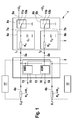
- FIG. 1 shows as a single figure a schematic block diagram of an alarm signaling device according to the invention in the form of a push button detector 1, which has an evaluation device 2 and a switching unit 3.
- Evaluation device 2 and switching unit 3 are arranged together in a (not shown) housing, which is made identifiable by molding and coloring as a push button detector 1.
- the housing is formed for example with a Einschlagrome.
- the switching unit 3 is housed in the housing and the evaluating means 2 is e.g. as part of a safety network spaced from the housing, e.g. placed in a central monitoring.
- electrical leads 4a, b are provided which lead parallel to the evaluation device 2 and to which each voltage U 1 is applied.
- the electrical leads 4a, b are through the evaluation device 2 looped through and lead as connecting lines 5a, b in the switching unit. 3
- the resistance element R 1 or R 2 is in each case connected in series in the connecting lines 5a, b, via the capacitance C 1 and C 2 , the connecting lines 5a, b connected to ground or ground.
- the time constants of the low-pass filters 6a, b are in the range of a few 100 ms in order to be able to intercept short bursts in this range.
- the low-pass filters may also be cascaded or realized on the basis of another technology, such as digital filters.
- the low-pass filters 6a, b are connected via two lines 7a, b each with a switching element 8 a, b, which are each switchable between two switching positions.
- the line 7a or b In the first switching position, the line 7a or b is connected to ground or earth, in the second switching position, the line 7a and b, respectively, connected to an associated output line 9a and b, which in turn are at the potential U 1 .
- the switching elements 8 a and b are actuated together via a common actuator (not shown).
- the switching elements 8 a, b shown in FIG. 1 are designed with normally closed contacts 10 a, b, so that the switching elements 8 a, b connect the line 7 a, b to earth or ground in the non-actuated state.
- a current I 1 or I 2 flows via the leads 4a and b to the respective ground or ground, these currents are hereinafter also referred to as monitoring currents.
- a resistor R 3 or R 4 is connected in series in the supply lines 4a and b, respectively.
- the respective electrical connection is opened and the lines 7a, b via the normally open contacts 11a, b to the output line 9a or 9b and thus to the potential U 1 .
- the evaluation device 2 has an evaluation module 12 which detects the potential of the two connection lines 5a and b as input signals and is designed to output output signals in the form of an alarm message via an alarm channel 13 and a fault message via a fault channel 14.
- the switching position of the switching elements 8a and b is detected by the potential of the connecting lines 5a and b by an alarm module 15 within the evaluation module 12, wherein the potential of ground or earth as a logical "LOW” and the potential U 1 as a logic "HIGH” is interpreted.
- a closed switching element 8a or b generates a logical "LOW” and an opened switching element 8a or b a logic "HIGH”.
- the switching position is detected as open, ie as a logic "HIGH", this state (AND) is interpreted as an alarm and an alarm message via the alarm channel 13 output.
- this state (XOR) of a fault module 16 as a possible defect of the push button detector. 1 interpreted and issued a fault message via the fault channel 14.
- both switching elements 8a and b must be actuated to trigger an alarm message 13.
- both switching elements must be operated within a time window with a length of 1 to 3 seconds. If the time interval between the switching operations is greater, a fault message is output instead of an alarm message.
- the pushbutton detector 1 has an optical display (not shown) in the housing, which indicates the current status of the alarm module 15 or fault module 16, so that the user can recognize whether an alarm has been triggered or if there is a fault.
- a monitoring unit 17 for monitoring the monitoring currents I 1 and I 2 is implemented so that it can be monitored whether there is a contact with the normally closed contacts 10a, b and / or the normally open contacts 11a, b. In this way, for example, corrosion of the switching contacts of the switching elements 8 a and b is monitored.
- the monitoring unit 17 is shown in two parts in FIG. 1, the first part of the monitoring unit 17 monitoring the current I 1 and the second part of the monitoring unit 17 monitoring the current I 2 .
- a common monitoring unit 17, which controls both monitoring currents I 1 and I 2 is preferred.
- the tap for the current monitoring can in principle take place at any point between the supply line 4a or b and the switching element 8a or b, as indicated by the dashed lines.
- the monitoring unit 17 is in the technical implementation either external and spaced, for example, in a central monitoring station (not shown), or arranged in the evaluation device 2 or in the switching unit 3 or as an independent module.
- the monitoring unit 17 generates a fault message in the event that the amount of the monitoring current I 1 and / or I 2 falls below a predetermined rest value or zero or if the measured monitoring current I 1 or I 2 jump its value by more than a relative amount of eg 50% changes.
- a sleep value tracking is implemented in the monitoring unit 17, wherein all changes in the monitoring current I 1 and / or I 2 , which do not trigger a fault message, lead to the setting of a new rest value, in particular by tracking the rest value.
- limit values are provided for the quiescent value or the measured monitoring current, with a fault message being generated when the limit value is exceeded by the measured monitoring current I 1 or I 2 and / or by the tracking quiescent value.
Landscapes
- Physics & Mathematics (AREA)
- General Physics & Mathematics (AREA)
- Engineering & Computer Science (AREA)
- Computer Security & Cryptography (AREA)
- Business, Economics & Management (AREA)
- Emergency Management (AREA)
- Alarm Systems (AREA)
Applications Claiming Priority (1)
| Application Number | Priority Date | Filing Date | Title |
|---|---|---|---|
| DE200610005182 DE102006005182A1 (de) | 2006-02-06 | 2006-02-06 | Manuell betätigbare Alarmmeldevorrichtung |
Publications (2)
| Publication Number | Publication Date |
|---|---|
| EP1816618A1 true EP1816618A1 (fr) | 2007-08-08 |
| EP1816618B1 EP1816618B1 (fr) | 2015-11-11 |
Family
ID=37930366
Family Applications (1)
| Application Number | Title | Priority Date | Filing Date |
|---|---|---|---|
| EP07100172.1A Not-in-force EP1816618B1 (fr) | 2006-02-06 | 2007-01-05 | Dispositif de signalisation d'alarme actionnable manuellement |
Country Status (2)
| Country | Link |
|---|---|
| EP (1) | EP1816618B1 (fr) |
| DE (1) | DE102006005182A1 (fr) |
Cited By (1)
| Publication number | Priority date | Publication date | Assignee | Title |
|---|---|---|---|---|
| DE102012024000A1 (de) | 2012-12-06 | 2014-06-12 | Cosi - Elektronik Gmbh | Notrufsender |
Citations (5)
| Publication number | Priority date | Publication date | Assignee | Title |
|---|---|---|---|---|
| US4162485A (en) * | 1975-07-14 | 1979-07-24 | Walter Kidde And Company, Inc. | Fire protection apparatus |
| EP0919888A1 (fr) * | 1997-05-09 | 1999-06-02 | Fanuc Ltd | Appareil de transfert de donnees |
| DE10260168A1 (de) * | 2002-12-20 | 2004-07-01 | Volkswagen Ag | Bedienungseinrichtung eines automatisierten Kfz-Getriebes |
| EP1460666A2 (fr) * | 2003-03-19 | 2004-09-22 | Siemens Aktiengesellschaft | Touche pour des procédés de commutation de sécurité |
| US20040245856A1 (en) * | 2003-06-09 | 2004-12-09 | Shoei-Lai Chen | Electrical switching device for preventing error pushing |
Family Cites Families (5)
| Publication number | Priority date | Publication date | Assignee | Title |
|---|---|---|---|---|
| DE2311519C3 (de) * | 1973-03-08 | 1984-07-26 | Siemens AG, 1000 Berlin und 8000 München | Feuermelder |
| US4743892A (en) * | 1987-01-08 | 1988-05-10 | Family Communications, Inc. | On-site personal monitoring system |
| DE3908885C1 (en) * | 1989-03-17 | 1990-05-03 | Siemens Ag, 1000 Berlin Und 8000 Muenchen, De | Alarm transmitter |
| CA2061508C (fr) * | 1991-11-04 | 2000-11-07 | Raymond Gilbert | Detecteur de fumee dote d'un selecteur automatique |
| DE9408898U1 (de) * | 1994-05-31 | 1995-09-28 | Zettler GmbH, 80469 München | Gefahrenmelder |
-
2006
- 2006-02-06 DE DE200610005182 patent/DE102006005182A1/de not_active Withdrawn
-
2007
- 2007-01-05 EP EP07100172.1A patent/EP1816618B1/fr not_active Not-in-force
Patent Citations (5)
| Publication number | Priority date | Publication date | Assignee | Title |
|---|---|---|---|---|
| US4162485A (en) * | 1975-07-14 | 1979-07-24 | Walter Kidde And Company, Inc. | Fire protection apparatus |
| EP0919888A1 (fr) * | 1997-05-09 | 1999-06-02 | Fanuc Ltd | Appareil de transfert de donnees |
| DE10260168A1 (de) * | 2002-12-20 | 2004-07-01 | Volkswagen Ag | Bedienungseinrichtung eines automatisierten Kfz-Getriebes |
| EP1460666A2 (fr) * | 2003-03-19 | 2004-09-22 | Siemens Aktiengesellschaft | Touche pour des procédés de commutation de sécurité |
| US20040245856A1 (en) * | 2003-06-09 | 2004-12-09 | Shoei-Lai Chen | Electrical switching device for preventing error pushing |
Cited By (3)
| Publication number | Priority date | Publication date | Assignee | Title |
|---|---|---|---|---|
| DE102012024000A1 (de) | 2012-12-06 | 2014-06-12 | Cosi - Elektronik Gmbh | Notrufsender |
| WO2014086339A2 (fr) | 2012-12-06 | 2014-06-12 | Cosi Elektronik Gmbh | Émetteur d'appel d'urgence |
| DE102012024000B4 (de) * | 2012-12-06 | 2015-10-01 | Cosi - Elektronik Gmbh | Notrufsender |
Also Published As
| Publication number | Publication date |
|---|---|
| EP1816618B1 (fr) | 2015-11-11 |
| DE102006005182A1 (de) | 2007-08-09 |
Similar Documents
| Publication | Publication Date | Title |
|---|---|---|
| DE102011008654B4 (de) | Beschlagsintegrierte Überwachungseinrichtung | |
| DE102015118151A1 (de) | Sicherheitssensor zur Überwachung der Betriebssicherheit einer Anlage | |
| CH681932A5 (fr) | ||
| DE2818305A1 (de) | Feuerloeschsystem | |
| EP0026461B1 (fr) | Circuit pour systèmes de détection d'intrusion ou d'incendie | |
| DE102014006343A1 (de) | Batteriegehäuse für eine Kraftfahrzeug-Batterie | |
| WO2019025496A1 (fr) | Vanne de système d'extinction d'incendie | |
| EP2136343B1 (fr) | Surveillance de conduite d'interrupteurs de fumée | |
| EP1816618B1 (fr) | Dispositif de signalisation d'alarme actionnable manuellement | |
| EP0014714A1 (fr) | Dispositif d'alarme partiellement amovible avec protection contre le non-fonctionnement, la panne, le sabotage et la fausse alarme | |
| EP0423489A1 (fr) | Arrangement pour la détection de fumée avec contrôle | |
| AT404980B (de) | Absperrvorrichtung für eine gasversorgungsleitung | |
| DE202018103509U1 (de) | Hauptsteuerventil für eine Feuerlöschanlage | |
| EP3295996A1 (fr) | Procédé de surveillance d'un dispositif de déclenchement d'une installation de protection contre l'incendie au moyen d'un courant d'essai estampé cycliquement ainsi que dispositif de commande de mise hors feu | |
| EP2191570B1 (fr) | Interface de raccordement d'un dispositif convertisseur à une ligne bipolaire | |
| DE19640739C1 (de) | Alarmspeicher-Schaltungsanordnung für Öffnungsmelder | |
| DE2224898B2 (de) | Ueberwachungs- und anregungsschaltung fuer aussenalarmmittel von sicherungsanlagen | |
| DE281992C (fr) | ||
| DE102004048585A1 (de) | Einbruchmeldeanlage | |
| DE2533978A1 (de) | Bedienungsvorrichtung fuer elektrische einbruchsmeldeanlagen | |
| DE3214439C2 (fr) | ||
| DE29823931U1 (de) | Schloß mit alarmauslösender Zuhaltevorrichtung | |
| DE2217014C3 (de) | Notausblocktaste | |
| DE19614675A1 (de) | Gefahrenmeldeanlage mit Videoüberwachung | |
| DE202020002219U1 (de) | Universelle Vorrichtung für Sicherheitsmodule zur Montage an einem beweglichen Tür- oder Fensterrahmen |
Legal Events
| Date | Code | Title | Description |
|---|---|---|---|
| PUAI | Public reference made under article 153(3) epc to a published international application that has entered the european phase |
Free format text: ORIGINAL CODE: 0009012 |
|
| AK | Designated contracting states |
Kind code of ref document: A1 Designated state(s): AT BE BG CH CY CZ DE DK EE ES FI FR GB GR HU IE IS IT LI LT LU LV MC NL PL PT RO SE SI SK TR |
|
| AX | Request for extension of the european patent |
Extension state: AL BA HR MK YU |
|
| 17P | Request for examination filed |
Effective date: 20080208 |
|
| 17Q | First examination report despatched |
Effective date: 20080313 |
|
| AKX | Designation fees paid |
Designated state(s): DE ES FR GB IT |
|
| GRAP | Despatch of communication of intention to grant a patent |
Free format text: ORIGINAL CODE: EPIDOSNIGR1 |
|
| INTG | Intention to grant announced |
Effective date: 20150624 |
|
| GRAS | Grant fee paid |
Free format text: ORIGINAL CODE: EPIDOSNIGR3 |
|
| GRAA | (expected) grant |
Free format text: ORIGINAL CODE: 0009210 |
|
| AK | Designated contracting states |
Kind code of ref document: B1 Designated state(s): DE ES FR GB IT |
|
| REG | Reference to a national code |
Ref country code: GB Ref legal event code: FG4D Free format text: NOT ENGLISH |
|
| REG | Reference to a national code |
Ref country code: DE Ref legal event code: R096 Ref document number: 502007014384 Country of ref document: DE |
|
| PG25 | Lapsed in a contracting state [announced via postgrant information from national office to epo] |
Ref country code: IT Free format text: LAPSE BECAUSE OF FAILURE TO SUBMIT A TRANSLATION OF THE DESCRIPTION OR TO PAY THE FEE WITHIN THE PRESCRIBED TIME-LIMIT Effective date: 20151111 Ref country code: ES Free format text: LAPSE BECAUSE OF FAILURE TO SUBMIT A TRANSLATION OF THE DESCRIPTION OR TO PAY THE FEE WITHIN THE PRESCRIBED TIME-LIMIT Effective date: 20151111 |
|
| REG | Reference to a national code |
Ref country code: DE Ref legal event code: R097 Ref document number: 502007014384 Country of ref document: DE |
|
| PLBE | No opposition filed within time limit |
Free format text: ORIGINAL CODE: 0009261 |
|
| STAA | Information on the status of an ep patent application or granted ep patent |
Free format text: STATUS: NO OPPOSITION FILED WITHIN TIME LIMIT |
|
| 26N | No opposition filed |
Effective date: 20160812 |
|
| REG | Reference to a national code |
Ref country code: FR Ref legal event code: ST Effective date: 20160930 |
|
| PG25 | Lapsed in a contracting state [announced via postgrant information from national office to epo] |
Ref country code: FR Free format text: LAPSE BECAUSE OF NON-PAYMENT OF DUE FEES Effective date: 20160201 |
|
| PGFP | Annual fee paid to national office [announced via postgrant information from national office to epo] |
Ref country code: GB Payment date: 20200127 Year of fee payment: 14 |
|
| GBPC | Gb: european patent ceased through non-payment of renewal fee |
Effective date: 20210105 |
|
| PG25 | Lapsed in a contracting state [announced via postgrant information from national office to epo] |
Ref country code: GB Free format text: LAPSE BECAUSE OF NON-PAYMENT OF DUE FEES Effective date: 20210105 |
|
| PGFP | Annual fee paid to national office [announced via postgrant information from national office to epo] |
Ref country code: DE Payment date: 20220324 Year of fee payment: 16 |
|
| REG | Reference to a national code |
Ref country code: DE Ref legal event code: R119 Ref document number: 502007014384 Country of ref document: DE |
|
| PG25 | Lapsed in a contracting state [announced via postgrant information from national office to epo] |
Ref country code: DE Free format text: LAPSE BECAUSE OF NON-PAYMENT OF DUE FEES Effective date: 20230801 |