EP1815650B1 - Procede de synchronisation et de transmission de donnees dans un reseau a sauts multiples - Google Patents
Procede de synchronisation et de transmission de donnees dans un reseau a sauts multiples Download PDFInfo
- Publication number
- EP1815650B1 EP1815650B1 EP05817554A EP05817554A EP1815650B1 EP 1815650 B1 EP1815650 B1 EP 1815650B1 EP 05817554 A EP05817554 A EP 05817554A EP 05817554 A EP05817554 A EP 05817554A EP 1815650 B1 EP1815650 B1 EP 1815650B1
- Authority
- EP
- European Patent Office
- Prior art keywords
- node
- synchronization signal
- nodes
- beacon
- synchronization
- Prior art date
- Legal status (The legal status is an assumption and is not a legal conclusion. Google has not performed a legal analysis and makes no representation as to the accuracy of the status listed.)
- Active
Links
- 238000000034 method Methods 0.000 title claims abstract description 80
- 230000005540 biological transmission Effects 0.000 title claims description 39
- 230000006854 communication Effects 0.000 claims abstract description 66
- 238000004891 communication Methods 0.000 claims abstract description 66
- 230000001360 synchronised effect Effects 0.000 claims abstract description 49
- 230000008859 change Effects 0.000 claims description 16
- 238000001514 detection method Methods 0.000 claims description 2
- 244000025221 Humulus lupulus Species 0.000 description 63
- 241001136792 Alle Species 0.000 description 7
- 230000006870 function Effects 0.000 description 7
- 238000005457 optimization Methods 0.000 description 5
- 230000008569 process Effects 0.000 description 4
- 241000854291 Dianthus carthusianorum Species 0.000 description 3
- 235000008694 Humulus lupulus Nutrition 0.000 description 3
- 230000002457 bidirectional effect Effects 0.000 description 3
- 238000011161 development Methods 0.000 description 3
- 230000001174 ascending effect Effects 0.000 description 2
- 238000005265 energy consumption Methods 0.000 description 2
- 238000012544 monitoring process Methods 0.000 description 2
- 230000006855 networking Effects 0.000 description 2
- 210000002023 somite Anatomy 0.000 description 2
- 230000009897 systematic effect Effects 0.000 description 2
- 206010012335 Dependence Diseases 0.000 description 1
- 235000009809 Humulus lupulus var lupuloides Nutrition 0.000 description 1
- 235000006878 Humulus lupulus var neomexicanus Nutrition 0.000 description 1
- 235000009800 Humulus lupulus var pubescens Nutrition 0.000 description 1
- 235000009808 Humulus lupulus var. lupulus Nutrition 0.000 description 1
- 101100478969 Oryza sativa subsp. japonica SUS2 gene Proteins 0.000 description 1
- 101100004663 Saccharomyces cerevisiae (strain ATCC 204508 / S288c) BRR2 gene Proteins 0.000 description 1
- 101100504519 Saccharomyces cerevisiae (strain ATCC 204508 / S288c) GLE1 gene Proteins 0.000 description 1
- 230000007175 bidirectional communication Effects 0.000 description 1
- 238000012790 confirmation Methods 0.000 description 1
- 230000001419 dependent effect Effects 0.000 description 1
- 238000010586 diagram Methods 0.000 description 1
- 230000009977 dual effect Effects 0.000 description 1
- 230000000694 effects Effects 0.000 description 1
- 238000005516 engineering process Methods 0.000 description 1
- 230000007613 environmental effect Effects 0.000 description 1
- 230000002045 lasting effect Effects 0.000 description 1
- 238000012423 maintenance Methods 0.000 description 1
- 238000013507 mapping Methods 0.000 description 1
- 230000000717 retained effect Effects 0.000 description 1
- 230000004622 sleep time Effects 0.000 description 1
- 229910000679 solder Inorganic materials 0.000 description 1
- 238000012546 transfer Methods 0.000 description 1
Images


Classifications
-
- H—ELECTRICITY
- H04—ELECTRIC COMMUNICATION TECHNIQUE
- H04B—TRANSMISSION
- H04B7/00—Radio transmission systems, i.e. using radiation field
- H04B7/24—Radio transmission systems, i.e. using radiation field for communication between two or more posts
- H04B7/26—Radio transmission systems, i.e. using radiation field for communication between two or more posts at least one of which is mobile
- H04B7/2662—Arrangements for Wireless System Synchronisation
- H04B7/2671—Arrangements for Wireless Time-Division Multiple Access [TDMA] System Synchronisation
- H04B7/2678—Time synchronisation
- H04B7/2687—Inter base stations synchronisation
- H04B7/269—Master/slave synchronisation
-
- H—ELECTRICITY
- H04—ELECTRIC COMMUNICATION TECHNIQUE
- H04W—WIRELESS COMMUNICATION NETWORKS
- H04W56/00—Synchronisation arrangements
- H04W56/001—Synchronization between nodes
-
- H—ELECTRICITY
- H04—ELECTRIC COMMUNICATION TECHNIQUE
- H04J—MULTIPLEX COMMUNICATION
- H04J3/00—Time-division multiplex systems
- H04J3/02—Details
- H04J3/06—Synchronising arrangements
- H04J3/0635—Clock or time synchronisation in a network
- H04J3/0679—Clock or time synchronisation in a network by determining clock distribution path in a network
-
- H—ELECTRICITY
- H04—ELECTRIC COMMUNICATION TECHNIQUE
- H04W—WIRELESS COMMUNICATION NETWORKS
- H04W56/00—Synchronisation arrangements
- H04W56/001—Synchronization between nodes
- H04W56/0015—Synchronization between nodes one node acting as a reference for the others
-
- H—ELECTRICITY
- H04—ELECTRIC COMMUNICATION TECHNIQUE
- H04W—WIRELESS COMMUNICATION NETWORKS
- H04W74/00—Wireless channel access, e.g. scheduled or random access
- H04W74/04—Scheduled or contention-free access
-
- H—ELECTRICITY
- H04—ELECTRIC COMMUNICATION TECHNIQUE
- H04W—WIRELESS COMMUNICATION NETWORKS
- H04W88/00—Devices specially adapted for wireless communication networks, e.g. terminals, base stations or access point devices
- H04W88/02—Terminal devices
- H04W88/04—Terminal devices adapted for relaying to or from another terminal or user
Definitions
- the invention relates to a method for forming a synchronized network for wireless communication between transceiver units, the so-called node (KN) and a central transceiver unit, the so-called central node (ZKN) in a multihop network.
- Multihop networks are used in many ways in the field of communication technology, for example in the monitoring of infrastructure elements or environmental monitoring.
- a multihop network basically consists of a multiplicity of network nodes, each of which has at least one transmitting / receiving device and one processor unit.
- data is typically transmitted from a first network node, the data source, to a second network node, the data sink, via a number of other network nodes serving as relay stations, called intermediate nodes.
- the first and second nodes can be selected arbitrarily.
- data exchange between network nodes becomes possible whose transmission and reception ranges do not overlap, ie which can not establish direct data communication with each other.
- Each network node can do this Data source, data sink and relay station.
- the individual network nodes for this purpose must be positioned relative to one another such that at least one further network node is located in the transmission / reception area of a network node, so that a meshed communication structure can thereby be created.
- a data exchange in a multi-hop network typically takes place by way of bidirectional wireless communication, in particular by way of radio communication.
- one or more network nodes may be distinguished by additional functions to be performed by them over the other network nodes. If, for example, a network node serves as the central data sink in the multihop network, then this is distinguished from the other network nodes by this function and is referred to below as the central node.
- the central node can also be assigned a different and / or further additional functions.
- a disadvantage of the currently known method for synchronization and communication of multihop networks is the considerable computational effort at the individual network nodes to build, to maintain, for continuous optimization of the network and for data communication within the network, and in particular the associated high power consumption at the individual network nodes ,
- the power supply of the individual network nodes takes place in many applications by a battery. To operate the individual network nodes as long as possible with battery, therefore, the power consumption for operation must be as low as possible. Even for central nodes, which forwards many data packets, a certain lifespan must be achieved. This requires a low duty cycle.
- the duty cycle is the ratio of active time, i. active communication, at sleep time, i. non-active communication of a node.
- a further disadvantage is that the so-called “hidden node” problem known per se can occur in the corresponding methods known today as a result of collisions in the radio communication. As a result, the "hidden node", i. the corresponding node, not reachable by the network.
- the US Pat. No. 6751248 B1 describes a method of establishing and maintaining synchronization between nodes and a master node in a multihop network.
- so-called parent nodes are selected that cover the entire network.
- the parent nodes regularly send synchronization information to the rest of the network.
- Parent nodes that do not interfere send this synchronization information simultaneously.
- a time division multiplex structure ensures that each node regularly receives synchronization information.
- the US 2003/0151513 A1 describes a self-organizing hierarchical wireless network comprising a cluster head network with at least one cluster head and a sensor / actuator network operating in a hierarchical manner with the cluster head network is arranged.
- a so-called ad-hoc multi-hop network which configures itself.
- the synchronization can take place via suitable beacon signals.
- the US Pat. No. 6,735,448 B1 describes energy management to reduce energy consumption in ad hoc wireless networks while increasing throughput. This is done by individually controlling the transmission power of the individual nodes as a function of the individual transmission distance. A transmission strategy that minimizes potential interference and minimizes the number of hops required for transmission minimizes collisions and retransmissions, increasing data throughput.
- the object of the present invention is to provide a method for collision-free synchronization and communication in a multihop network, which is characterized by a low power consumption and by a low duty cycle.
- the method should at least largely avoid the listed problems of previous methods. In particular, it should be possible to generate redundant communication paths in order to increase the reliability. Furthermore, the "hidden node" problem should be avoided.
- the method according to the invention for synchronization and communication is based on a multi-hop network which has a central node and a plurality of nodes.
- the network can be infinitely large, ie the network can comprise any number of nodes.
- the method also serves to maintain synchronization during normal operation of the network.
- the central node as well as the nodes each have a transceiver unit, a memory unit and a processor unit.
- the individual nodes can be stationary or mobile.
- the power supply of the accounts and the central node via accumulators, the power grid or locally generated, for example, by solar cells.
- the central node and the nodes are spatially positioned relative to one another in such a way that at least one further node or the central node is located in the transmission / reception area of each node.
- Each node is thus in direct communication with at least one other node or the central node.
- the communication between a node that is outside the transmission / reception area of the central node and the central node takes place with the inclusion of additional nodes as relay stations (so-called intermediate nodes) via a multi-hop communication. This makes it possible for nodes that do not have a direct communication relationship to the central node communicate their data via the intermediate nodes to the central node.
- the central node is distinguished from the other nodes in the network in that it serves as a reference point for the communication paths in the network and also as a time base for the synchronization of the network nodes, and thus of the entire network. After synchronization of the network, therefore, all nodes derive their time base from the central node. Of course, can be taken over from the central node more functions in the network, for example. He can serve as a central data sink or he can have the network controlling tasks. Due to the additional functions of the central node, the hardware equipment of the central node from the other nodes, for example, by a larger memory or higher computing power, differ.
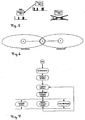
- FIG. 1 illustrates these conceptual definitions on the example of a multi-hop network, consisting of a central node K1 and the nodes K2 - K9.
- the individual distributed nodes are represented by ellipses.
- the arrows between the ellipses represent the existing communication structure in the network.
- the ellipses also indicate the identifier assigned to each node or the hop count value resulting from the existing communication structure.
- the central node is assigned the hop count value 0.
- the assignment of a specific hop count value to a node, as well as its assignment to a layer, depends on the actually selected communication path. If this changes, the hop count value or the layer affiliation of a node can also change.
- the in FIG. 1 mappings of the hop count value 2. to nodes K5, K8 and K6 as well as the hop count value 3 to nodes K7 and K9.
- the respective same hop count value thus also determines the affiliation of the nodes K5, K6 and K8 to the layer 2 as well as the nodes K7 and K9 to the layer 3.
- the individual layers are in FIG. 1 represented as those nodes that are included together by a dark area.
- the communication between the individual nodes in the multi-hop network is based on wireless data transmission in frames, which are subdivided into defined slots.
- bidirectional communication methods in particular radio methods, are preferably used, the following data transmission protocols Use: Time Division Multiple Access (TDMA), Frequency Division Multiple Access (FDMA), Code Division Multiple Access (CDMA).
- TDMA Time Division Multiple Access
- FDMA Frequency Division Multiple Access
- CDMA Code Division Multiple Access
- Subdivisions of the frame into data areas, preferably in a synchronization, neighboring node and data area come into consideration depending on the application, for example, at the same time normal communication data and data that serve the synchronization, maintenance and optimization of the network structure, in a frame to send.
- the frame structure ie the frame duration, the number of slots or the subdivision of the frame into areas, the network can be adapted during operation to special conditions by a parameterization.
- a synchronization signal is transmitted from the central node or from an already synchronized node, wherein a slot defined by the transmitting node in the frame of the synchronization signal, the so-called beacon slot, is occupied.
- a beacon slot once defined by a transmitting node is in principle also retained for the transmissions of further synchronization signals by the respective node. Exceptions to this will be described separately below.
- At least the following data are sent with each synchronization signal or as a separately transmitted data packet in connection with a synchronization signal: for all already synchronized neighbors of the transmitting node, the beacons slots already occupied by these neighbors as well as the respective hop count values of these neighbors.
- the beacon slots occupied by the already synchronized direct neighbors of a transmitting node and their hop count values are additionally transmitted in each case as well.
- the number of successors of the sending node in the network is additionally transmitted.
- the beacon slot thus assigned to a node and the hop count value have the function of an individual identifier in the network at one time, which is unique for the direct neighbors. Furthermore, this enables collision-free communication between the nodes. An additional individual identifier of each node in the network is thus not required but of course possible and even required for certain applications of the method.
- the synchronization signals or related data packets are received by all neighbors of the sending node, i. from both the already synchronized and the not yet synchronized neighbors, received and evaluated.
- the not yet synchronized neighbors receive with the synchronization signal a time base on which they synchronize themselves.
- the already synchronized neighbors of the node advantageously use the synchronization signal to verify their synchronization.
- the respective beacon slot assignment and the hop count values of its already synchronized next but one neighbors are advantageously also determined and stored.
- each node selects its communication chain to the central node.
- the node With the corresponding selection of the predecessor, the node itself further assigns a hop count value higher by the number one than the hop count value of the selected predecessor.
- each node In normal operation, ie after all nodes are synchronized and the regular data exchange is taking place throughout the network, each node continues to receive the synchronization signal of its predecessor to maintain synchronization and sends its own synchronization signal to reach its successors.
- the node exchanges data packets with its neighboring nodes. In the background, he constantly determines his active neighbors and thus recognizes changes, at least in the local network structure.
- the local neighborhood relationships for a node change for two successive synchronization signals received by it, for example by adding further synchronized neighbor nodes in the network or by removing or failing already synchronized neighboring nodes, this is done by the node by comparing the currently received neighborhood information with the stored ones previous neighborhood information detected.
- the method according to the invention means that the network always adapts to changes in the network. If, for example, the predecessor of a node is removed from the network, the node will determine a new predecessor according to the predetermined criteria.
- the node can already participate in the normal data communication of the already synchronized multi-hop network after receiving the first synchronization signal.
- the described method steps are repeated at least until all nodes in the network are synchronized. Preferably, however, the method is operated in parallel to the normal communication.
- the central node At the beginning of synchronization, initially only the central node sends out synchronization signals.
- the other nodes assume a receive mode (sniff mode).
- the central node can therefore occupy any beacon slot, for example the beacon slot 1, before the transmission of its first synchronization signal.
- the neighboring nodes of the central node receive the described synchronization signal of the central node, store the transmitted data or evaluate it and synchronize its respective time base to the time base of the central node.
- the already synchronized nodes in turn send out their own synchronization signal without collision, so that the nodes further away from the central node can synchronize.
- the still free beacon slots are occupied, ie, in the present example, the beacon slots 2, 3, 4, etc., as well as neighborhood information present at the transmitting node are transmitted.
- the neighboring nodes of the central node which are synchronized in the course of the method thus form the first synchronized layer around the central node, the second synchronized layer, etc., further up to and including the central node all nodes are synchronized. If no beacon slot is free, the node becomes an end node.
- the first embodiment describes an embodiment of the method according to the invention for synchronization, communication in a distributed multi-hop network, with a central node and a plurality of nodes.
- network data will be sent from the nodes to the central node, on the other hand, the reverse way is possible.
- a low duty cycle of approximately 0.02% for transmitting / receiving data can be realized in order to ensure a long service life of the battery-operated sensors.
- Each node discovers all its neighboring nodes regularly and with low energy expenditure. It is the optimal connection to the central node found during operation and there is no manual intervention to install or to find out of failure routes needed.
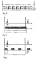
- FIG. 2 shows the frame structure preferably selected in this embodiment for the synchronization signal.
- the frame itself is divided into a synchronization area, a neighboring node area and a data area.
- the individual beacon slots are arranged in the synchronization area.
- the beacon slot assignment of the adjacent nodes is communicated.
- the actual data communication of the network takes place in the data area.
- Each node is identifiable at a given time by its hop count h with 0 ⁇ h ⁇ n and the beacon slot s with 0 ⁇ ssk.
- the highest hop count value in the FIG. 2 example is n
- the highest beacon slot value is k.
- the node marked by h and s sends its beacon in Beaconslot s and layer h of the synchronization area.
- the node is assigned a slot in each of the three frame areas, which slot is determined by the layer h and the beacon slot s of the respective node. Because the layers in the regions are sorted in ascending order, the beacon propagates in a short time to the last layer n of the network.
- a node If a node has collected this information from all neighbors, it can determine its optimal predecessor and a free beacon slot. This creates a collision-free network with balanced ramifications to the central node.
- the nodes alternate frame by frame with the transmission of neighboring node information.
- the beacon slots occupied in the synchronization area determine when which node sends the neighboring node information.
- Each node synchronized to the central node receives the beacon of its predecessor or a neighbor in a given beacon slot and transmits its own beacon with a synchronization signal.
- a node synchronizes to the frame beginning. The synchronization takes place exclusively through the beacons in the beacon slot and is thus independent of the concept of data transmission.
- the nodes can send data packets to their neighbors.
- the values for Hop Count and Beaconslot can be used to structure the data area to reduce collisions.
- the method for data transmission itself is largely arbitrary in the given framework and known to the person skilled in the art.
- the method is based on the rule that each node is responsible for synchronizing itself and finding the best path to the base. Synchronization and route optimization are decentralized in the nodes. The following rules apply:
- An unsynchronized node is initially in the so-called sniff mode, i. a mode by not sending but trying to receive a synchronization signal with a beacon to synchronize.
- sniff mode i. a mode by not sending but trying to receive a synchronization signal with a beacon to synchronize.
- FIG. 3 a process variant of the sniff mode is shown.
- FIG. 3 illustrates the time frame of a frame defined by the frame start and frame period.
- the readiness for reception of the node is indicated by the black time bar overlapping the frame period.
- the black time bar represents the time interval of t sniff , max .
- FIG. 4 shows analogous to FIG. 3 a frame and a beacon transmitted therein in a time interval t sync .
- the receptivity of the node is also represented by the black time bars. If the receiver of the non-synchronized node can only be active for a short time, it periodically hears the maximum possible reception duration in this variant and then recharges its capacities.
- the node As soon as the node receives a beacon, it synchronizes to the beginning of the frame for all procedures. If several neighbors send their beacon in a frame period without collision, the synchronization time is shortened because the reception probability multiplies by the number of neighbors.
- Unsuccessful synchronization requires a lot of energy because the receiver has been active for at least a full frame period without successfully completing the synchronization.
- the next attempt after a failure may only take place after days. Only then can a long battery life be guaranteed.
- FIG. 5 illustrates that in the present embodiment, a node sends out a synchronization signal only if it has received a beacon from its selected predecessor. This ensures both a common time base for the entire network and a continuous connection to the central node.
- node 1 has received a beacon from its selected predecessor, node 0.
- node 1 in turn sends out a synchronization signal.
- the beacon of the selected predecessor is received in each frame period.
- each node in the background scans all beacon slots or the corresponding data signals in the neighborhood area to determine new neighbors. So he can optimize his route to the central node or immediately select another neighbor from his list in case of failure of the selected predecessor.
- To optimize the communication structure is selected by each node of the predecessor of (, S ignal Received S trength I ndication RSSI) value having the lowest hop count value, the least successors and the highest received signal strength. The hop count value takes precedence over the successor number and has priority over the received signal strength. If a better neighbor is found, it is selected as the predecessor and the own hop count value is adjusted accordingly.
- the node announces the change in the beacon.
- the followers receive the announcement and try to receive the beacon on the new beacon slot. This preserves the existing communication channels. Other neighbors only notice that a new beacon slot is being used. If the identifier of the node does not appear in a new beacon slot, the node has failed or is taken off the network.
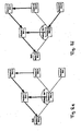
- FIG. 6 illustrates the hidden node problem. Shown are the nodes A, B and C as well as the radio range of nodes A and C. If node B is in the middle of two neighbors A and C and A and C in the same beacon slot send their beacon, then the beacons collide at the node B, without the nodes A or C can notice. In an extreme case, the node B can neither be reached by C nor by A.
- a node is preferably maintained its beacon slot for at least two synchronization phases, as in a shorter change of the beacon slot no systematic synchronization of an unsynchronized node is possible.
- the selection of the new Beaconslots takes place according to the criteria described above.
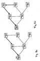
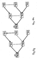
- the Figures 8a - 8g showing structure of the corresponding communication structures in a network consisting of the five nodes with the associated node numbers 0 to 5.
- the nodes are shown as rectangular boxes in which the node number and the current beacon slot are specified.
- the basically possible radio links are shown as thin connecting lines.
- the actually selected communication connections are marked with thicker arrows.
- the central node has the node number 0.
- FIG. 8a shows as a thin connecting lines, the principle possible communication links between the individual nodes due to the respective overlapping transmitting and receiving areas of each node.
- the base node sends a synchronization signal with a beacon in beacon slot 0. All other nodes are unsynchronized and try to receive a beacon in sniff mode.
- FIG. 8b time that node 1 received the beacon of the base node and has synchronized to the beginning frame.
- the predecessor selected by the node 1 is the central node.
- the hop count value of node 1 is thus 1. Since beacon slot 0 is already occupied by the central node, node 1 sends its beacon to beacon slot 1.
- FIG. 8c shows that the node 2 has synchronized with the synchronization signal transmitted by node 1 and has selected node 1 as predecessor.
- FIG. 8d shows that node 3 has synchronized to node 2 and has chosen beacon slot 0 for the transmission of its own beacon. This is possible because the beacon slot 0 is neither used by the direct neighbor (node 2) nor the next but one neighbor (node 1) of node 3. Thus, both from the point of view of node 0 and node 3, a dual use of the beacon slot 0 is protected to the next but one neighbor.
- the optimal one over node 4 can not yet be found by node 3, since node 4 is not yet synchronized, therefore it does not send its own beacon and thus is not yet known to node 3.
- FIG. 8d shows that node 3 has synchronized to node 2 and has chosen beacon slot 0 for the transmission of its own beacon. This is possible because the beacon slot 0 is neither used by the direct neighbor (node 2) nor the next but one neighbor (node 1) of node 3. Thus, both from the point of view of node 0 and node 3, a dual use of the beacon slot 0 is protected to the next but
- node 4 receives synchronization signals from the node 0 as well as from node 3 with the beacon slot 0. This creates collisions in node 4, so that neither node 0 nor node 3 is visible for node 4 (hidden node problem).
- the only node visible to node 4 is node 1.
- Node 4 therefore synchronizes to node 1 and consequently sends its beacon to beaconslot 3, since node 4 can see from synchronization signal of node 1 that node 1 occupies beacon slot 1 and the neighbors of node 1 (node 0 and node 2) occupy the beacon slots 0 and 2.
- a sensor node first synchronizes to the first beacon that it receives in sniff mode and specifies its predecessor. This means that the sensor node is time-synchronized with the already active network and can now selectively individual in each cycle Listen to beaconslots to find a more suitable predecessor (beacon). To ensure that this does not take too long, a time-synchronous sensor node searches a larger number of beacon slots in each cycle with pauses lasting about 60 ms. After n cycles, the sensor node has listened to all beacon slots and is synchronized to the optimal beacon. Each sensor node that has finally synchronized to a beacon sends a Sync_ind message to the central node for confirmation. Theoretically, this can already be done after the sensor node has synchronized to the first beacon.
- the central node After a certain number of cycles, the central node has received all the identifiers of the synchronized sensor nodes of a layer. The central node then appoints a sensor node per layer and housing cluster to the repeater node and assigns each repeater node a different beacon slot greater than 1.
- the central node first appoints the repeater nodes, which however only begin to send their beacon almost simultaneously after a later broadcast command. This creates, for example, in a ten-story house with ten apartments per floor, 100 repeater nodes. There may be a few more if a dwelling is only partially covered by a lower layer beacon. It is advantageous in this case in the apartment part, which then belongs to the next higher layer, nor provide an additional repeater node.
- Each repeater node regularly sends its beacon in the beacon slot assigned to it.
- the remaining sensor nodes which have not been designated as a repeater node, communicate via a beacon node of the next lower sphere with the central node.
- the remaining sensor nodes of a housing cluster ie all sensor nodes of a dwelling that did not become repeater nodes, synchronize to the repeater node with their dwelling identifier.
- This also has energetic advantages, since within a dwelling the communication link better than over a floor.
- the data transmission of the sensor nodes takes place via their respective repeaters and the path of the repeater nodes in the individual layers which has been defined during the synchronization.
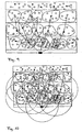
- FIG. 9 schematically branches the distribution of sensor nodes in a 4-storey building.
- the individual sensor nodes (white circles) are assigned to the floors of individual apartment clusters. In each housing cluster, a sensor node was selected as a repeater node. There is a communication structure (black arrows) between the repeater nodes, which enables the communication of the repeater nodes with the central node on the ground floor of the building.
- the individual sensor nodes always select the repeater node in their respective housing cluster for their communication with the central node, for example as predecessors.
- FIG. 10 differs from Rick in that the transmission and reception ranges of individual repeater nodes are illustrated by circles.
- Each sensor node in the transmission area of the central node receives the beacon of the central node (hop count 0), synchronizes to this and responds to the master with a Sync_ind message in a data slot.
- the beacon can max. 8 - 10 ms long. With a data rate of 100 kbaud and a Manchester coding, this corresponds to approximately 50 - 62 bytes, which are available for a beacon. Theoretically, one could also refrain from occupying the beacon slots again after a few hops or layers, but one could have a separate beacon slot for each repeater node. In this example case, there would be a 1-2 second long beacon frame after a repeater count of 100-200. This method would be particularly useful in the following alternative case.
- beacon slot was about 60-70 ms long and you forgive the beacon slots in ascending order.
- Each predecessor repeater node sends in a lower beacon slot. Then each repeater node in a beacon slot can receive the beacon of its predecessor repeater node and send its own beacon in one of the next beacon slots. This allows commands to be transmitted very quickly upwards. You would, however, depending on the number of repeaters and exact slot length a very long beacon frame of about 6-14 seconds in length.
- the long beacon slot times are in this case due to the fact that it is theoretically possible for a beacon to be received in one slot and to be forwarded directly in the next slot. After receiving the beacon, however, a charging time of about 50-60 ms is required. If you can guarantee that there are always at least 5 slots in the slot sequence, you can also work with 10 ms slots.
- the data transmission in the network is preferably based on a contention-based method.
- the second embodiment describes the stepwise synchronization of a bidirectional wireless read-out network, which is subsequently kept synchronous. Due to a special syntax, each sensor node receives a unique identifier during assembly in an apartment, which contains the number of the apartment as well as the corresponding floor. This allows a logical clustering of flats. By naming beacon repeater nodes within a logical cluster (dwelling), a hierarchical structure of the system automatically results and the routing paths for the communication are determined. In addition, it is conceivable to organize the beacon repeater nodes in a higher-level network. To optimize the power consumption, the repeater task should be periodically transferred to neighboring nodes.
Claims (25)
- Procédé de synchronisation et de communication dans un réseau multi-sauts, avec plusieurs noeuds KN, et un noeud central ZKN, qui comportent chacun au moins une unité émettrice/réceptrice, une unité de mémoire, ainsi qu'une unité de processeur, la communication entre les unités émettrices/réceptrices reposant sur une transmission de données sans fil dans des trames, qui sont divisées en des intervalles définis, les KN et le ZKN étant physiquement positionnés l'un par rapport à l'autre de sorte que dans la zone émettrice/réceptrice de chaque KN se trouve au moins un autre KN en tant que voisin de ce dernier et/ou le ZKN, dans la mesure où le KN se situe à l'extérieur de la zone émettrice/réceptrice du ZKN, la communication entre un KN et le ZKN s'effectuant en impliquant d'autres KN, en tant que noeuds intermédiaires, via une communication multi-sauts, et à chaque KN étant affectée au moins une valeur de compteur de sauts, qui indique le nombre de noeuds intermédiaires augmenté de un pour le KN respectif, par l'intermédiaire desquels la communication avec le SKN s'effectue, le noeud intermédiaire suivant le KN dans le réseau lors de la communication étant désigné comme prédécesseur du KN, le KN étant désigné comme successeur du noeud intermédiaire et tous les KN de mêmes valeurs de compteur de sauts étant désignés comme couche avec les étapes de procédé suivantes :a) Emission d'un signal de synchronisation par le ZKN ou par un KN d'ores et déjà synchronisé, un intervalle fixé par le noeud émettant le signal de synchronisation étant occupé dans la trame du signal de synchronisation, le dénommé intervalle balise par un paquet de données permettant la synchronisation, la dénommée balise et au moins la valeur de compteur de sauts du noeud émetteur étant transmise dans la trame du signal de synchronisation et pour tous les noeuds voisins du noeud émetteur qui sont d'ores et déjà synchronisés, qui sont connus par le noeud émetteur, transmission des intervalles balises respectifs occupés par les noeuds voisins et des valeurs de compteur de sauts du noeud voisin dans la trame du signal de synchronisation ou en tant que signal de données séparé par le noeud émetteur,b) Réception du signal de synchronisation, ainsi que des données transmises en association avec celui-ci par un premier KN situé dans la zone émettrice/réceptrice du noeud émetteur,c) Synchronisation du premier KN sur le signal de synchronisation,d) Détermination des voisins du premier KN, ainsi que de leur occupation respective par l'intervalle balise et de valeurs du compteur de sauts par le premier KN,e) Fixation du prédécesseur du premier KN dans le réseau par le premier KN, sur la base de critères prédéfinis,f) Mise en mémoire des données réceptionnées avec le signal de synchronisation et en association avec ce dernier, ainsi que de données déterminées à partir de celui-ci par le premier KN,g) Répétition des étapes a) à f), au moins jusqu'à la synchronisation de tous les KN.
- Procédé selon la revendication 1,
caractérisé en ce que la délivrance du signal de synchronisation par le ZKN s'effectue de façon régulièrement récurrente. - Procédé selon la revendication 1 ou 2,
caractérisé en ce que les étapes a) à f) sont également réalisées de façon récurrente, même après achèvement de la synchronisation de tous les KN. - Procédé selon l'une quelconque des revendications 1 à 3, caractérisé en ce qu'avec le signal de synchronisation ou avec un signal de données séparé qui est en association avec ce dernier, les intervalles balises d'ores et déjà occupés par ces derniers et des valeurs de compteur de sauts sont transmis en supplément pour tous les voisins synchronisés du KN ou ZKN délivrant le signal de synchronisation.
- Procédé selon l'une quelconque des revendications 1 à 4, caractérisé en ce que la détermination du prédécesseur du premier KN repose sur la sélection du voisin avec la plus faible valeur de compteur de sauts.
- Procédé selon l'une quelconque des revendications 1 à 5, caractérisé en ce que la détermination du prédécesseur du premier KN repose sur la sélection du voisin avec le moins de successeurs.
- Procédé selon l'une quelconque des revendications 1 à 6, caractérisé en ce que pour la détermination du prédécesseur du premier KN, des données des deuxièmes prochains voisins du premier KN sont impliquées.
- Procédé selon l'une quelconque des revendications 1 à 7, caractérisé en ce que la détermination du prédécesseur du premier KN repose sur la sélection du voisin dont le signal de synchronisation avec la plus grande intensité de signal a été réceptionné par le premier KN.
- Procédé selon l'une quelconque des revendication 5 à 8, caractérisé en ce que lors de la détermination du prédécesseur, une association de critères individuels ou de tous les critères selon les revendications 5 à 8 est prise en considération.
- Procédé selon l'une quelconque des revendications 1 à 9, caractérisé en ce qu'à la délivrance du signal de synchronisation, le noeud émetteur sélectionne son intervalle balise dans la trame, de sorte que soit sélectionné un intervalle balise inoccupé jusqu'au deuxième prochain voisin du noeud émetteur.
- Procédé selon l'une quelconque des revendications 1 à 10, caractérisé en ce qu'un KN qui ne trouve aucun intervalle balise libre devient un noeud final qui ne délivre aucun signal de synchronisation.
- Procédé selon l'une quelconque des revendications 1 à 11, caractérisé en ce que pour chaque couche, il est réservé un nombre d'intervalles balises dans la trame du signal de synchronisation.
- Procédé selon l'une quelconque des revendications 1 à 12, caractérisé en ce qu'il est prévu dans la trame du signal de synchronisation un nombre d'intervalles balises au moins égal au nombre de chevauchement de zones émettrices/réceptrices d'unités émettrices/réceptrices individuelles.
- Procédé selon l'une quelconque des revendications 1 à 13,
caractérisé en ce qu'un KN ne délivre son propre signal de synchronisation qu'après réception du signal de synchronisation de son prédécesseur. - Procédé selon l'une quelconque des revendications 1 à 14, caractérisé en ce que chaque KN délivrant un signal de synchronisation utilise son intervalle balise sélectionné une fois au moins sur un temps limité, à chaque délivrance ultérieure d'un signal de synchronisation.
- Procédé selon l'une quelconque des revendications 1 à 15, caractérisé en ce que le ZKN ou un KN délivre un signal de synchronisation, qui par rapport à des signaux de synchronisation émis précédemment par le ZKN ou par le KN respectif comporte un intervalle balise modifié dans la trame.
- Procédé selon l'une quelconque des revendications 1 à 16, caractérisé en ce qu'avant la délivrance d'un signal de synchronisation par un KN, le KN sélectionne un intervalle balise qui se distingue des intervalles balises qu'utilisent ses voisins.
- Procédé selon l'une quelconque des revendications 1 à 16, caractérisé en ce que, avant la délivrance du signal de synchronisation par un KN, le KN sélectionne un intervalle balise qui se distingue des intervalles balises qu'utilisent ses voisins et ses deuxièmes prochains voisins.
- Procédé selon la revendication 16,
caractérisé en ce qu'une modification imminente pour un KN de son intervalle balise utilisé jusqu'à présent par le KN est envoyé en tant qu'information de données aux voisins respectifs, avant sa réalisation par le KN. - Procédé selon l'une quelconque des revendications 1 à 19, caractérisé en ce que chaque KN évalue notamment les signaux de synchronisation, ainsi que les données de son prédécesseur sélectionné qui sont en relation avec ce dernier et les compare avec les données mémorisées du signal de synchronisation précédemment réceptionné et en cas de divergences, il s'effectue une nouvelle détermination du prédécesseur selon l'étape de procédé e) selon la revendication 1.
- Procédé selon l'une quelconque des revendications 1 à 20, caractérisé en ce que les protocoles TDMA (Time Division Multiple Access) (Accès Multiple à Répartition dans le Temps (AMRT), FDMA- (Frequency Division Multiple Access) (Accès Multiple par Répartition de Fréquence (AMRF)) ou CDMA (Code Division Multiple Access) (Accès Multiple par Répartition de Fréquence (AMRF)) sont utilisés pour la transmission de données.
- Procédé selon l'une quelconque des revendications 1 à 21, caractérisé en ce que chaque noeud, ainsi que le noeud central disposent d'une propre identification, qui est transmise respectivement avec le signal de synchronisation.
- Procédé selon la revendication 22,
caractérisé en ce qu'après sa synchronisation, un noeud envoie au noeud central un Syncsignal, qui comprend au moins son identification. - Procédé selon l'une quelconque des revendications 1 à 23,
caractérisé en ce que les trames comportent une structure de trame qui comporte au moins une zone de synchronisation, dans laquelle des intervalles balises sont transmis et au moins une zone de données, dans laquelle des données sont transmises. - Procédé selon la revendication 24,
caractérisé en ce que dans la zone de synchronisation et dans la zone de données, il est prévu respectivement pour chaque noeud un intervalle individuel, qui est déterminé par sa valeur de compteur de sauts et par son intervalle balise sélectionné.
Priority Applications (1)
| Application Number | Priority Date | Filing Date | Title |
|---|---|---|---|
| PL05817554T PL1815650T3 (pl) | 2004-11-25 | 2005-11-22 | Sposób synchronizacji i transmisji danych |
Applications Claiming Priority (2)
| Application Number | Priority Date | Filing Date | Title |
|---|---|---|---|
| DE102004057080 | 2004-11-25 | ||
| PCT/DE2005/002089 WO2006056174A1 (fr) | 2004-11-25 | 2005-11-22 | Procede de synchronisation et de transmission de donnees dans un reseau a sauts multiples |
Publications (2)
| Publication Number | Publication Date |
|---|---|
| EP1815650A1 EP1815650A1 (fr) | 2007-08-08 |
| EP1815650B1 true EP1815650B1 (fr) | 2009-03-18 |
Family
ID=36013347
Family Applications (1)
| Application Number | Title | Priority Date | Filing Date |
|---|---|---|---|
| EP05817554A Active EP1815650B1 (fr) | 2004-11-25 | 2005-11-22 | Procede de synchronisation et de transmission de donnees dans un reseau a sauts multiples |
Country Status (8)
| Country | Link |
|---|---|
| US (1) | US8767705B2 (fr) |
| EP (1) | EP1815650B1 (fr) |
| AT (1) | ATE426289T1 (fr) |
| DE (2) | DE112005003430A5 (fr) |
| DK (1) | DK1815650T3 (fr) |
| ES (1) | ES2324486T3 (fr) |
| PL (1) | PL1815650T3 (fr) |
| WO (1) | WO2006056174A1 (fr) |
Cited By (2)
| Publication number | Priority date | Publication date | Assignee | Title |
|---|---|---|---|---|
| DE102010047946A1 (de) * | 2010-10-08 | 2012-04-12 | Metrona Wärmemesser Union Gmbh | Verfahren zur Konfiguration eines Netzwerks von Netzknoten sowie Verfahren und Vorrichtungsanordnung zur Übermittlung von Verbrauchsdaten dezentral angeordneter Datenerfassungsgeräte |
| EP2560453A2 (fr) | 2011-08-19 | 2013-02-20 | Fraunhofer-Gesellschaft zur Förderung der angewandten Forschung e.V. | Procédé de connexion de réseau |
Families Citing this family (50)
| Publication number | Priority date | Publication date | Assignee | Title |
|---|---|---|---|---|
| US7142107B2 (en) | 2004-05-27 | 2006-11-28 | Lawrence Kates | Wireless sensor unit |
| EP1905200A1 (fr) | 2005-07-01 | 2008-04-02 | Terahop Networks, Inc. | Acheminement de reseau non deterministe et deterministe |
| WO2007066637A1 (fr) * | 2005-12-05 | 2007-06-14 | Nec Corporation | Procede et systeme de communication sans fil |
| US20090129306A1 (en) * | 2007-02-21 | 2009-05-21 | Terahop Networks, Inc. | Wake-up broadcast including network information in common designation ad hoc wireless networking |
| EP1940190B1 (fr) * | 2006-12-29 | 2013-11-20 | Motorola Mobility LLC | Dispositif de communication cellulaire sans fil et procédé de gestion de la réception d'une commande de transfert |
| US7729336B2 (en) | 2007-03-28 | 2010-06-01 | Harris Corporation | Synchronization and timing source priority in an ad-hoc network |
| US8780885B2 (en) | 2007-07-09 | 2014-07-15 | Qualcomm Incorporated | Synchronization of a peer-to-peer communication network |
| US20130100947A9 (en) * | 2007-07-09 | 2013-04-25 | Qualcomm Incorporated | Methods and apparatus for timing synchronization using multiple different timing signal sources |
| US7983702B2 (en) | 2007-07-09 | 2011-07-19 | Qualcomm Incorporated | Synchronization of a peer-to-peer communication network |
| US8811372B2 (en) * | 2007-07-09 | 2014-08-19 | Qualcomm Incorporated | Synchronization of a peer-to-peer communication network |
| EP2034629A1 (fr) | 2007-09-05 | 2009-03-11 | Technische Universität Kaiserlautern | Procédé, produit de programme informatique et système pour la synchronisation de nýuds dans un réseau à sauts multiples sans fil |
| JP5183228B2 (ja) * | 2008-01-30 | 2013-04-17 | ラピスセミコンダクタ株式会社 | マルチホップ無線通信システム |
| US8583154B2 (en) * | 2008-03-25 | 2013-11-12 | Siemens Aktiengesellschaft | Energy and time-efficient set-up of a wireless communication system |
| WO2009151877A2 (fr) | 2008-05-16 | 2009-12-17 | Terahop Networks, Inc. | Systèmes et appareil de fixation d’un conteneur |
| EP2139168A1 (fr) * | 2008-06-25 | 2009-12-30 | Thomson Licensing, Inc. | Procédé et dispositif de synchronisation temporelle dans un réseau sans fil à sauts multiples AMRT |
| KR101179299B1 (ko) * | 2008-12-03 | 2012-09-03 | 한국전자통신연구원 | 시분할 접속을 이용한 메쉬 센서 네트워크에서 모니터링 응용을 위한 저전력 센서 노드 및 이의 라우팅 방법 |
| US8391435B2 (en) | 2008-12-25 | 2013-03-05 | Google Inc. | Receiver state estimation in a duty cycled radio |
| US8619754B2 (en) * | 2009-01-15 | 2013-12-31 | Essence Security International Ltd. | Robust channel allocation method for RF communication systems |
| US8730938B2 (en) * | 2009-04-08 | 2014-05-20 | Qualcomm Incorporated | Minimizing the impact of self synchronization on wireless communication devices |
| US8848622B2 (en) * | 2009-07-22 | 2014-09-30 | Qualcomm Incorporated | Methods and apparatus for improving power efficiency and latency of mobile devices using an external timing source |
| US8565169B2 (en) * | 2010-01-12 | 2013-10-22 | Qualcomm Incorporated | Timing synchronization methods and apparatus |
| US8995380B2 (en) * | 2012-03-22 | 2015-03-31 | Texas Instruments Incorporated | Scheduling in a multi-hop wireless network |
| WO2014016922A1 (fr) * | 2012-07-25 | 2014-01-30 | 富士通株式会社 | Dispositif de traitement de données, système de traitement de données et procédé de traitement de données |
| CN104838609B (zh) * | 2012-12-09 | 2018-11-20 | Lg电子株式会社 | 无线通信中获覆盖范围内外用户设备间同步的方法及设备 |
| EP3624471B1 (fr) * | 2013-01-16 | 2022-05-04 | Huawei Technologies Co., Ltd. | Procédé d'accès à un réseau pour terminal mobile et terminal mobile |
| WO2015001657A1 (fr) | 2013-07-04 | 2015-01-08 | 富士通株式会社 | Système de gestion de réseau de données, dispositif de gestion de réseau de données, dispositif de traitement de données, et procédé de gestion de réseau de données |
| US9603113B2 (en) * | 2013-10-29 | 2017-03-21 | Qualcomm Incorporated | Distributed algorithm for constructing and maintaining a hierarchical structure for device-to-device synchronization |
| WO2015109961A1 (fr) * | 2014-01-24 | 2015-07-30 | Telefonaktiebolaget L M Ericsson (Publ) | Procédé et appareil d'émission de signaux de synchronisation d2d |
| WO2015115795A1 (fr) * | 2014-01-28 | 2015-08-06 | 엘지전자 주식회사 | Procédé et appareil pour permettre à un terminal de dispositif à dispositif d'acquérir une synchronisation dans un système de communication sans fil |
| US10165533B2 (en) * | 2014-05-09 | 2018-12-25 | Sun Patent Trust | Device to device synchronization source selection |
| CN106416370B (zh) * | 2014-06-11 | 2019-08-02 | Lg电子株式会社 | 无线通信系统中中继用于终端到终端直接通信的发现信号的方法及其装置 |
| JP5823072B1 (ja) * | 2015-03-16 | 2015-11-25 | 明日電子有限公司 | 時計システム及び時刻同期方法 |
| US10028276B2 (en) * | 2016-02-25 | 2018-07-17 | Electronics And Telecommunications Research Institute | Node device and method of allocating resources in wireless sensor networks |
| US10506536B2 (en) | 2017-03-07 | 2019-12-10 | Itron Networked Solutions, Inc. | Time distribution scheme for wireless mesh networks |
| EP3593473A4 (fr) * | 2017-03-07 | 2021-01-06 | Itron Networked Solutions, Inc. | Schéma de distribution temporelle pour réseaux maillés sans fil |
| US10477500B2 (en) | 2017-03-07 | 2019-11-12 | Itron Networked Solutions, Inc. | Time distribution scheme for wireless mesh networks |
| US10397821B2 (en) * | 2017-03-07 | 2019-08-27 | Itron Networked Solutions, Inc. | Reduced latency operating modes for wireless mesh networks |
| WO2018204584A1 (fr) | 2017-05-04 | 2018-11-08 | Carrier Corporation | Système de réseaux sans fil synchronisés comprenant une identité à base temporelle de dispositifs |
| US11122490B2 (en) | 2018-11-28 | 2021-09-14 | Guy McIlroy | Message frame disambiguation in a flood fill mesh radio network |
| US10833938B1 (en) * | 2019-07-31 | 2020-11-10 | Oracle International Corporation | Methods, systems, and computer readable media for network function (NF) topology synchronization |
| EP3813444A1 (fr) * | 2019-10-23 | 2021-04-28 | Mitsubishi Electric R&D Centre Europe B.V. | Synchronisation d'un noeud connecté |
| US11070348B1 (en) * | 2019-12-16 | 2021-07-20 | Facebook, Inc. | Time synchronization of a wireless network |
| US11528334B2 (en) | 2020-07-31 | 2022-12-13 | Oracle International Corporation | Methods, systems, and computer readable media for preferred network function (NF) location routing using service communications proxy (SCP) |
| US11290549B2 (en) | 2020-08-24 | 2022-03-29 | Oracle International Corporation | Methods, systems, and computer readable media for optimized network function (NF) discovery and routing using service communications proxy (SCP) and NF repository function (NRF) |
| US11483694B2 (en) | 2020-09-01 | 2022-10-25 | Oracle International Corporation | Methods, systems, and computer readable media for service communications proxy (SCP)-specific prioritized network function (NF) discovery and routing |
| US11570262B2 (en) | 2020-10-28 | 2023-01-31 | Oracle International Corporation | Methods, systems, and computer readable media for rank processing for network function selection |
| US11470544B2 (en) | 2021-01-22 | 2022-10-11 | Oracle International Corporation | Methods, systems, and computer readable media for optimized routing of messages relating to existing network function (NF) subscriptions using an intermediate forwarding NF repository function (NRF) |
| US11895080B2 (en) | 2021-06-23 | 2024-02-06 | Oracle International Corporation | Methods, systems, and computer readable media for resolution of inter-network domain names |
| US11563638B1 (en) | 2021-08-27 | 2023-01-24 | Oracle International Corporation | Methods, systems, and computer readable media for optimizing network bandwidth utilization through intelligent updating of network function (NF) profiles with NF repository function |
| US11849506B2 (en) | 2021-10-08 | 2023-12-19 | Oracle International Corporation | Methods, systems, and computer readable media for routing inter-public land mobile network (inter-PLMN) messages related to existing subscriptions with network function (NF) repository function (NRF) using security edge protection proxy (SEPP) |
Family Cites Families (12)
| Publication number | Priority date | Publication date | Assignee | Title |
|---|---|---|---|---|
| AU1974795A (en) * | 1994-03-03 | 1995-09-18 | Proxim, Inc. | Frequency hopping medium access control protocol |
| JP3187280B2 (ja) * | 1995-05-23 | 2001-07-11 | シャープ株式会社 | 面照明装置 |
| US6751248B1 (en) * | 1999-12-07 | 2004-06-15 | Koninklijke Philips Electronics N.V. | Method for nodes in a multi-hop wireless network to acquire and maintain synchronization with a master node |
| GB9930132D0 (en) * | 1999-12-22 | 2000-02-09 | Ericsson Telefon Ab L M | Telecommunication network synchronisation |
| US6735448B1 (en) * | 2000-11-07 | 2004-05-11 | Hrl Laboratories, Llc | Power management for throughput enhancement in wireless ad-hoc networks |
| DE10062303C2 (de) * | 2000-12-14 | 2002-11-28 | Layers Ag 7 | Verfahren zum Betrieb eines Ad Hoc-Netzwerkes zur drahtlosen Datenübertragung von synchronen und asynchronen Nachrichten |
| JP4105090B2 (ja) * | 2001-08-25 | 2008-06-18 | ノキア コーポレイション | 近傍情報及び公示伝送時間を利用する無衝突伝送スケジューリングのためのシステム及び方法 |
| US7180915B2 (en) * | 2001-12-21 | 2007-02-20 | Nokia Corporation | Apparatus, and an associated method, for facilitating synchronization in a wireless mesh network |
| US20030151513A1 (en) * | 2002-01-10 | 2003-08-14 | Falk Herrmann | Self-organizing hierarchical wireless network for surveillance and control |
| US7072432B2 (en) * | 2002-07-05 | 2006-07-04 | Meshnetworks, Inc. | System and method for correcting the clock drift and maintaining the synchronization of low quality clocks in wireless networks |
| US7304981B2 (en) * | 2002-09-09 | 2007-12-04 | Itt Manufacturing Enterprises Inc. | Apparatus and method of flywheel time-of-day (TOD) synchronization |
| JP2005094169A (ja) * | 2003-09-16 | 2005-04-07 | Sony Corp | 無線通信システム、無線通信装置及び無線通信方法、並びにコンピュータ・プログラム |
-
2005
- 2005-11-22 ES ES05817554T patent/ES2324486T3/es active Active
- 2005-11-22 US US11/791,546 patent/US8767705B2/en active Active
- 2005-11-22 DE DE112005003430T patent/DE112005003430A5/de not_active Withdrawn
- 2005-11-22 WO PCT/DE2005/002089 patent/WO2006056174A1/fr active Application Filing
- 2005-11-22 DK DK05817554T patent/DK1815650T3/da active
- 2005-11-22 PL PL05817554T patent/PL1815650T3/pl unknown
- 2005-11-22 DE DE502005006901T patent/DE502005006901D1/de active Active
- 2005-11-22 AT AT05817554T patent/ATE426289T1/de active
- 2005-11-22 EP EP05817554A patent/EP1815650B1/fr active Active
Cited By (5)
| Publication number | Priority date | Publication date | Assignee | Title |
|---|---|---|---|---|
| DE102010047946A1 (de) * | 2010-10-08 | 2012-04-12 | Metrona Wärmemesser Union Gmbh | Verfahren zur Konfiguration eines Netzwerks von Netzknoten sowie Verfahren und Vorrichtungsanordnung zur Übermittlung von Verbrauchsdaten dezentral angeordneter Datenerfassungsgeräte |
| EP2439911B1 (fr) * | 2010-10-08 | 2017-04-19 | Metrona Wärmemesser Union Gmbh | Procédé de configuration d'un réseau de noeuds de réseau ainsi que procédé et agencement de dispositif de transmission de données d'utilisation d'appareils de détection de données agencés de manière décentralisée |
| EP2560453A2 (fr) | 2011-08-19 | 2013-02-20 | Fraunhofer-Gesellschaft zur Förderung der angewandten Forschung e.V. | Procédé de connexion de réseau |
| DE102011081269A1 (de) | 2011-08-19 | 2013-02-21 | Fraunhofer-Gesellschaft zur Förderung der angewandten Forschung e.V. | Verfahren zur Netzwerkorganisation |
| US9300595B2 (en) | 2011-08-19 | 2016-03-29 | Fraunhofer-Gesellschaft Zur Foerderung Der Angewandten Forschung E.V. | Method for network organization |
Also Published As
| Publication number | Publication date |
|---|---|
| WO2006056174A1 (fr) | 2006-06-01 |
| US8767705B2 (en) | 2014-07-01 |
| DE112005003430A5 (de) | 2007-10-31 |
| US20080165761A1 (en) | 2008-07-10 |
| PL1815650T3 (pl) | 2009-08-31 |
| EP1815650A1 (fr) | 2007-08-08 |
| ATE426289T1 (de) | 2009-04-15 |
| DE502005006901D1 (de) | 2009-04-30 |
| ES2324486T3 (es) | 2009-08-07 |
| DK1815650T3 (da) | 2009-07-20 |
Similar Documents
| Publication | Publication Date | Title |
|---|---|---|
| EP1815650B1 (fr) | Procede de synchronisation et de transmission de donnees dans un reseau a sauts multiples | |
| DE69432810T2 (de) | Frequenzsprungmusterzuteilung und Steuerung in mehreren autonom angeordneten Funknetzen | |
| DE60021868T2 (de) | Kommunikationsnetzwerk und verfahren zur zuteilung von ressourcen für sanftes weiterreichen | |
| DE112004000662T5 (de) | Verfahren und Vorrichtung zum Verteilen von Kommunikationssignalen | |
| WO2004038959A1 (fr) | Procede de synchronisation decentralisee dans un systeme de communication radio auto-organise | |
| EP1759537B1 (fr) | Procede d'etablissement d'un reseau de communication auto-organise sans fil et transfert de fonctionnalite de station de base | |
| DE10053809A1 (de) | Adhoc-Netzwerk mit mehreren Terminals zur Bestimmung von Terminals als Controller von Sub-Netzwerken | |
| DE19950005A1 (de) | Verfahren zum Betrieb drahtloser Basisstationen für paketvermittelnde Funksysteme mit garantierter Dienstgüte | |
| DE3337648A1 (de) | Funknetz mit einer vielzahl von mobilen stationen | |
| EP2237592A2 (fr) | Procédé d'optimisation de structures de réseau dans des réseaux radio | |
| DE102021103225A1 (de) | LoRaWAN-Gateway-Netzwerk und Verfahren | |
| WO2010128134A1 (fr) | Balise pour réseau en étoile, noeuds capteurs dans un réseau en étoile, procédé d'initialisation d'une passerelle dans un réseau en étoile, et procédé d'utilisation d'un réseau en étoile | |
| DE102011081269A1 (de) | Verfahren zur Netzwerkorganisation | |
| EP1860830B1 (fr) | Procédé d'installation d'un réseau hiérarchique | |
| EP1678890B1 (fr) | Procede et dispositif pour determiner des chemins et attribuer des ressources radio aux chemins determines dans un systeme de communication radio | |
| WO2013087432A1 (fr) | Procédé de transmission de données dans un réseau de communication | |
| EP2859766B1 (fr) | Procédé et système de synchronisation temporelle dans un réseau ad hoc | |
| EP2566104B1 (fr) | Procédé et appareil destinés à transmettre des données dans un réseau radio partagé de manière hiérarchique | |
| DE112007000206B4 (de) | Verfahren und Vorrichtung zum Betreiben eines Knotens in einem Beacon-basierten Ad-hoc-Netz | |
| WO2010105921A1 (fr) | Procédé et dispositif pour la transmission écoénergétique de données dans un réseau de capteurs sans fil | |
| EP2592872B1 (fr) | Procédé de fonctionnement d'un réseau de liaison à plusieurs bonds | |
| DE102012101849B4 (de) | Verfahren zur Organisation und/oder Inbetriebnahme eines Netzwerkes zur Kommunikation und Netzwerkknoten | |
| DE102007055195A1 (de) | Verfahren zum Betrieb und zum Aufbau eines Funknetzwerks | |
| DE102008034694A1 (de) | Datenverarbeitungsvorrichtung zur Kommunikation mit anderen Datenverarbeitungsvorrichtungen | |
| EP2859745B1 (fr) | Procédé et système réseau permettant d'identifier efficacement des noeuds voisins |
Legal Events
| Date | Code | Title | Description |
|---|---|---|---|
| PUAI | Public reference made under article 153(3) epc to a published international application that has entered the european phase |
Free format text: ORIGINAL CODE: 0009012 |
|
| 17P | Request for examination filed |
Effective date: 20070531 |
|
| AK | Designated contracting states |
Kind code of ref document: A1 Designated state(s): AT BE BG CH CY CZ DE DK EE ES FI FR GB GR HU IE IS IT LI LT LU LV MC NL PL PT RO SE SI SK TR |
|
| 17Q | First examination report despatched |
Effective date: 20070912 |
|
| DAX | Request for extension of the european patent (deleted) | ||
| GRAP | Despatch of communication of intention to grant a patent |
Free format text: ORIGINAL CODE: EPIDOSNIGR1 |
|
| GRAS | Grant fee paid |
Free format text: ORIGINAL CODE: EPIDOSNIGR3 |
|
| GRAA | (expected) grant |
Free format text: ORIGINAL CODE: 0009210 |
|
| AK | Designated contracting states |
Kind code of ref document: B1 Designated state(s): AT BE BG CH CY CZ DE DK EE ES FI FR GB GR HU IE IS IT LI LT LU LV MC NL PL PT RO SE SI SK TR |
|
| REG | Reference to a national code |
Ref country code: GB Ref legal event code: FG4D Free format text: NOT ENGLISH |
|
| REG | Reference to a national code |
Ref country code: CH Ref legal event code: EP |
|
| REG | Reference to a national code |
Ref country code: IE Ref legal event code: FG4D Free format text: LANGUAGE OF EP DOCUMENT: GERMAN |
|
| REF | Corresponds to: |
Ref document number: 502005006901 Country of ref document: DE Date of ref document: 20090430 Kind code of ref document: P |
|
| REG | Reference to a national code |
Ref country code: CH Ref legal event code: NV Representative=s name: RENTSCH & PARTNER |
|
| REG | Reference to a national code |
Ref country code: SE Ref legal event code: TRGR |
|
| REG | Reference to a national code |
Ref country code: DK Ref legal event code: T3 |
|
| PG25 | Lapsed in a contracting state [announced via postgrant information from national office to epo] |
Ref country code: SI Free format text: LAPSE BECAUSE OF FAILURE TO SUBMIT A TRANSLATION OF THE DESCRIPTION OR TO PAY THE FEE WITHIN THE PRESCRIBED TIME-LIMIT Effective date: 20090318 Ref country code: LT Free format text: LAPSE BECAUSE OF FAILURE TO SUBMIT A TRANSLATION OF THE DESCRIPTION OR TO PAY THE FEE WITHIN THE PRESCRIBED TIME-LIMIT Effective date: 20090318 |
|
| REG | Reference to a national code |
Ref country code: ES Ref legal event code: FG2A Ref document number: 2324486 Country of ref document: ES Kind code of ref document: T3 |
|
| PG25 | Lapsed in a contracting state [announced via postgrant information from national office to epo] |
Ref country code: LV Free format text: LAPSE BECAUSE OF FAILURE TO SUBMIT A TRANSLATION OF THE DESCRIPTION OR TO PAY THE FEE WITHIN THE PRESCRIBED TIME-LIMIT Effective date: 20090318 |
|
| REG | Reference to a national code |
Ref country code: PL Ref legal event code: T3 |
|
| REG | Reference to a national code |
Ref country code: IE Ref legal event code: FD4D |
|
| PG25 | Lapsed in a contracting state [announced via postgrant information from national office to epo] |
Ref country code: PT Free format text: LAPSE BECAUSE OF FAILURE TO SUBMIT A TRANSLATION OF THE DESCRIPTION OR TO PAY THE FEE WITHIN THE PRESCRIBED TIME-LIMIT Effective date: 20090827 Ref country code: CZ Free format text: LAPSE BECAUSE OF FAILURE TO SUBMIT A TRANSLATION OF THE DESCRIPTION OR TO PAY THE FEE WITHIN THE PRESCRIBED TIME-LIMIT Effective date: 20090318 Ref country code: EE Free format text: LAPSE BECAUSE OF FAILURE TO SUBMIT A TRANSLATION OF THE DESCRIPTION OR TO PAY THE FEE WITHIN THE PRESCRIBED TIME-LIMIT Effective date: 20090318 Ref country code: IE Free format text: LAPSE BECAUSE OF FAILURE TO SUBMIT A TRANSLATION OF THE DESCRIPTION OR TO PAY THE FEE WITHIN THE PRESCRIBED TIME-LIMIT Effective date: 20090318 |
|
| PG25 | Lapsed in a contracting state [announced via postgrant information from national office to epo] |
Ref country code: IS Free format text: LAPSE BECAUSE OF FAILURE TO SUBMIT A TRANSLATION OF THE DESCRIPTION OR TO PAY THE FEE WITHIN THE PRESCRIBED TIME-LIMIT Effective date: 20090718 Ref country code: SK Free format text: LAPSE BECAUSE OF FAILURE TO SUBMIT A TRANSLATION OF THE DESCRIPTION OR TO PAY THE FEE WITHIN THE PRESCRIBED TIME-LIMIT Effective date: 20090318 Ref country code: RO Free format text: LAPSE BECAUSE OF FAILURE TO SUBMIT A TRANSLATION OF THE DESCRIPTION OR TO PAY THE FEE WITHIN THE PRESCRIBED TIME-LIMIT Effective date: 20090318 |
|
| PLBE | No opposition filed within time limit |
Free format text: ORIGINAL CODE: 0009261 |
|
| STAA | Information on the status of an ep patent application or granted ep patent |
Free format text: STATUS: NO OPPOSITION FILED WITHIN TIME LIMIT |
|
| PG25 | Lapsed in a contracting state [announced via postgrant information from national office to epo] |
Ref country code: BG Free format text: LAPSE BECAUSE OF FAILURE TO SUBMIT A TRANSLATION OF THE DESCRIPTION OR TO PAY THE FEE WITHIN THE PRESCRIBED TIME-LIMIT Effective date: 20090618 |
|
| 26N | No opposition filed |
Effective date: 20091221 |
|
| PG25 | Lapsed in a contracting state [announced via postgrant information from national office to epo] |
Ref country code: MC Free format text: LAPSE BECAUSE OF NON-PAYMENT OF DUE FEES Effective date: 20091130 |
|
| PG25 | Lapsed in a contracting state [announced via postgrant information from national office to epo] |
Ref country code: GR Free format text: LAPSE BECAUSE OF FAILURE TO SUBMIT A TRANSLATION OF THE DESCRIPTION OR TO PAY THE FEE WITHIN THE PRESCRIBED TIME-LIMIT Effective date: 20090619 |
|
| PG25 | Lapsed in a contracting state [announced via postgrant information from national office to epo] |
Ref country code: IT Free format text: LAPSE BECAUSE OF NON-PAYMENT OF DUE FEES Effective date: 20091122 |
|
| PG25 | Lapsed in a contracting state [announced via postgrant information from national office to epo] |
Ref country code: LU Free format text: LAPSE BECAUSE OF NON-PAYMENT OF DUE FEES Effective date: 20091122 |
|
| PG25 | Lapsed in a contracting state [announced via postgrant information from national office to epo] |
Ref country code: HU Free format text: LAPSE BECAUSE OF FAILURE TO SUBMIT A TRANSLATION OF THE DESCRIPTION OR TO PAY THE FEE WITHIN THE PRESCRIBED TIME-LIMIT Effective date: 20090919 |
|
| REG | Reference to a national code |
Ref country code: CH Ref legal event code: PFA Owner name: FRAUNHOFER-GESELLSCHAFT ZUR FOERDERUNG DER ANGEWA Free format text: FRAUNHOFER-GESELLSCHAFT ZUR FOERDERUNG DER ANGEWANDTEN FORSCHUNG E.V.#HANSASTRASSE 27C#80686 MUENCHEN (DE) -TRANSFER TO- FRAUNHOFER-GESELLSCHAFT ZUR FOERDERUNG DER ANGEWANDTEN FORSCHUNG E.V.#HANSASTRASSE 27C#80686 MUENCHEN (DE) |
|
| PGRI | Patent reinstated in contracting state [announced from national office to epo] |
Ref country code: IT Effective date: 20110616 |
|
| PG25 | Lapsed in a contracting state [announced via postgrant information from national office to epo] |
Ref country code: TR Free format text: LAPSE BECAUSE OF FAILURE TO SUBMIT A TRANSLATION OF THE DESCRIPTION OR TO PAY THE FEE WITHIN THE PRESCRIBED TIME-LIMIT Effective date: 20090318 |
|
| PG25 | Lapsed in a contracting state [announced via postgrant information from national office to epo] |
Ref country code: CY Free format text: LAPSE BECAUSE OF FAILURE TO SUBMIT A TRANSLATION OF THE DESCRIPTION OR TO PAY THE FEE WITHIN THE PRESCRIBED TIME-LIMIT Effective date: 20090318 |
|
| REG | Reference to a national code |
Ref country code: FR Ref legal event code: PLFP Year of fee payment: 11 |
|
| REG | Reference to a national code |
Ref country code: FR Ref legal event code: PLFP Year of fee payment: 12 |
|
| REG | Reference to a national code |
Ref country code: CH Ref legal event code: PCAR Free format text: NEW ADDRESS: BELLERIVESTRASSE 203 POSTFACH, 8034 ZUERICH (CH) |
|
| REG | Reference to a national code |
Ref country code: FR Ref legal event code: PLFP Year of fee payment: 13 |
|
| PGFP | Annual fee paid to national office [announced via postgrant information from national office to epo] |
Ref country code: PL Payment date: 20221109 Year of fee payment: 18 Ref country code: BE Payment date: 20221118 Year of fee payment: 18 |
|
| P01 | Opt-out of the competence of the unified patent court (upc) registered |
Effective date: 20230524 |
|
| PGFP | Annual fee paid to national office [announced via postgrant information from national office to epo] |
Ref country code: NL Payment date: 20231122 Year of fee payment: 19 |
|
| PGFP | Annual fee paid to national office [announced via postgrant information from national office to epo] |
Ref country code: GB Payment date: 20231123 Year of fee payment: 19 |
|
| PGFP | Annual fee paid to national office [announced via postgrant information from national office to epo] |
Ref country code: ES Payment date: 20231215 Year of fee payment: 19 |
|
| PGFP | Annual fee paid to national office [announced via postgrant information from national office to epo] |
Ref country code: SE Payment date: 20231123 Year of fee payment: 19 Ref country code: IT Payment date: 20231130 Year of fee payment: 19 Ref country code: FR Payment date: 20231123 Year of fee payment: 19 Ref country code: FI Payment date: 20231120 Year of fee payment: 19 Ref country code: DK Payment date: 20231122 Year of fee payment: 19 Ref country code: DE Payment date: 20231120 Year of fee payment: 19 Ref country code: CH Payment date: 20231201 Year of fee payment: 19 Ref country code: AT Payment date: 20231117 Year of fee payment: 19 |
|
| PGFP | Annual fee paid to national office [announced via postgrant information from national office to epo] |
Ref country code: PL Payment date: 20231110 Year of fee payment: 19 Ref country code: BE Payment date: 20231121 Year of fee payment: 19 |