EP1813496A1 - Roller way for container transport - Google Patents
Roller way for container transport Download PDFInfo
- Publication number
- EP1813496A1 EP1813496A1 EP06101006A EP06101006A EP1813496A1 EP 1813496 A1 EP1813496 A1 EP 1813496A1 EP 06101006 A EP06101006 A EP 06101006A EP 06101006 A EP06101006 A EP 06101006A EP 1813496 A1 EP1813496 A1 EP 1813496A1
- Authority
- EP
- European Patent Office
- Prior art keywords
- container
- drive units
- containers
- conveying system
- conveyor
- Prior art date
- Legal status (The legal status is an assumption and is not a legal conclusion. Google has not performed a legal analysis and makes no representation as to the accuracy of the status listed.)
- Withdrawn
Links
Images


Classifications
-
- B—PERFORMING OPERATIONS; TRANSPORTING
- B65—CONVEYING; PACKING; STORING; HANDLING THIN OR FILAMENTARY MATERIAL
- B65G—TRANSPORT OR STORAGE DEVICES, e.g. CONVEYORS FOR LOADING OR TIPPING, SHOP CONVEYOR SYSTEMS OR PNEUMATIC TUBE CONVEYORS
- B65G13/00—Roller-ways
- B65G13/02—Roller-ways having driven rollers
-
- B—PERFORMING OPERATIONS; TRANSPORTING
- B61—RAILWAYS
- B61B—RAILWAY SYSTEMS; EQUIPMENT THEREFOR NOT OTHERWISE PROVIDED FOR
- B61B13/00—Other railway systems
- B61B13/12—Systems with propulsion devices between or alongside the rails, e.g. pneumatic systems
- B61B13/127—Systems with propulsion devices between or alongside the rails, e.g. pneumatic systems the propulsion device consisting of stationary driving wheels
-
- B—PERFORMING OPERATIONS; TRANSPORTING
- B65—CONVEYING; PACKING; STORING; HANDLING THIN OR FILAMENTARY MATERIAL
- B65G—TRANSPORT OR STORAGE DEVICES, e.g. CONVEYORS FOR LOADING OR TIPPING, SHOP CONVEYOR SYSTEMS OR PNEUMATIC TUBE CONVEYORS
- B65G21/00—Supporting or protective framework or housings for endless load-carriers or traction elements of belt or chain conveyors
- B65G21/08—Protective roofs or arch supports therefor
-
- B—PERFORMING OPERATIONS; TRANSPORTING
- B65—CONVEYING; PACKING; STORING; HANDLING THIN OR FILAMENTARY MATERIAL
- B65G—TRANSPORT OR STORAGE DEVICES, e.g. CONVEYORS FOR LOADING OR TIPPING, SHOP CONVEYOR SYSTEMS OR PNEUMATIC TUBE CONVEYORS
- B65G23/00—Driving gear for endless conveyors; Belt- or chain-tensioning arrangements
- B65G23/22—Arrangements or mountings of driving motors
-
- B—PERFORMING OPERATIONS; TRANSPORTING
- B65—CONVEYING; PACKING; STORING; HANDLING THIN OR FILAMENTARY MATERIAL
- B65G—TRANSPORT OR STORAGE DEVICES, e.g. CONVEYORS FOR LOADING OR TIPPING, SHOP CONVEYOR SYSTEMS OR PNEUMATIC TUBE CONVEYORS
- B65G35/00—Mechanical conveyors not otherwise provided for
- B65G35/06—Mechanical conveyors not otherwise provided for comprising a load-carrier moving along a path, e.g. a closed path, and adapted to be engaged by any one of a series of traction elements spaced along the path
-
- B—PERFORMING OPERATIONS; TRANSPORTING
- B65—CONVEYING; PACKING; STORING; HANDLING THIN OR FILAMENTARY MATERIAL
- B65G—TRANSPORT OR STORAGE DEVICES, e.g. CONVEYORS FOR LOADING OR TIPPING, SHOP CONVEYOR SYSTEMS OR PNEUMATIC TUBE CONVEYORS
- B65G39/00—Rollers, e.g. drive rollers, or arrangements thereof incorporated in roller-ways or other types of mechanical conveyors
- B65G39/10—Arrangements of rollers
- B65G39/12—Arrangements of rollers mounted on framework
-
- B—PERFORMING OPERATIONS; TRANSPORTING
- B65—CONVEYING; PACKING; STORING; HANDLING THIN OR FILAMENTARY MATERIAL
- B65G—TRANSPORT OR STORAGE DEVICES, e.g. CONVEYORS FOR LOADING OR TIPPING, SHOP CONVEYOR SYSTEMS OR PNEUMATIC TUBE CONVEYORS
- B65G2201/00—Indexing codes relating to handling devices, e.g. conveyors, characterised by the type of product or load being conveyed or handled
- B65G2201/02—Articles
- B65G2201/0235—Containers
- B65G2201/0261—Puck as article support
-
- Y—GENERAL TAGGING OF NEW TECHNOLOGICAL DEVELOPMENTS; GENERAL TAGGING OF CROSS-SECTIONAL TECHNOLOGIES SPANNING OVER SEVERAL SECTIONS OF THE IPC; TECHNICAL SUBJECTS COVERED BY FORMER USPC CROSS-REFERENCE ART COLLECTIONS [XRACs] AND DIGESTS
- Y02—TECHNOLOGIES OR APPLICATIONS FOR MITIGATION OR ADAPTATION AGAINST CLIMATE CHANGE
- Y02T—CLIMATE CHANGE MITIGATION TECHNOLOGIES RELATED TO TRANSPORTATION
- Y02T30/00—Transportation of goods or passengers via railways, e.g. energy recovery or reducing air resistance
Definitions
- the present invention relates to transportation of goods, and more particularly to a method and apparatus for transporting containers.
- the object underlying the present invention is to provide a solution to the above-mentioned problems.
- the invention consists of a method for transporting containers according to claim 1 and a conveyor system according to claim 9.
- the container train was invented, for the most possible removal of increasingly problematic long-distance trucks from the highways.
- the invention is intended to ensure a smooth, safe and fast transport of the goods, exclusively with containers.
- the whole thing is based on a novel construction that can be built both on the highway, as well as independently on new terrain. If it leads over new terrain, then the route can be conducted as cheaply as possible, since this is still to be determined in contrast to the motorway.
- the construction consists of a covered and with side walls provided route (hall-like), in which the track is, which can be mounted on both concrete and steel pads.
- the container track is a novel form of transport for containers. It consists of a construction equipped with wheels (rollers), on which the containers are moved, rather than with remote trucks. It can be housed along its entire length in a kind of hall, which is completely covered with solar cells, both the roof and the side walls and can thus produce their own power requirements. At the same time, it would thus be totally shielded from all external influences, such as weather and unauthorized persons.
- these may be equipped with flip-up pantographs (or similar) by drawing the power eg from a power line.
- a power line This can be mounted under the roof at a height that allows at least "high-cube" container (with a height of 2.90m) to transport underneath. But this line can also elsewhere, for example, be mounted sideways. If electricity is generated in abundance with the many solar cells, then you can feed it into the public grid, or, if necessary, remove it again from the grid.
- the transport can run uninterrupted from the start to the destination, day and night, regardless of holidays and weather. Arrived at the destination, the containers are brought to the customer via the road, for example, and vice versa from the customer to the container train.
- the principle of the "container track” The container track consists of two adjacent lanes running in one direction and two more which run parallel to these in the opposite direction, just like the highway. These double strands serve exclusively for the transport of containers. Since the left lane (in the direction of travel) is located on the outer edge of the container track on each double strand, it would be best suited as a runway, exit lane and exit lane. The right-hand lane, on the other hand, only serves as an overtaking and avoidance lane when needed, eg in case of major repairs. Via the median strips and the evasion strips of the motorway, these areas along the container track are used as routes for maintenance crews. In addition to the outer driveways workshops are built and so that the spare parts need not be transported too far, come at reasonable intervals, the spare parts warehouse.
- the container train is, so to speak, a common means of transport, and yet every single container runs independently and independently, its destination inexorably. With it, only the container is transported and without fuel, but with the self-produced, or (if necessary) taken from the grid current.
- the wear is attributable to the mechanical, electrical and electronic devices, but they are limited here, among other things because all the replacement elements are standardized and the whole is not exposed to the effects of the weather. Also, the downtime of the long-distance trucks during the repair and maintenance times.
- the drive units of the container track are (as mentioned in the previous article) mounted so that in case of failure of one or more drive units at the same time, under the smallest container still enough functional drive units are to ensure the further transport.
- the drive units are only switched on when needed. If no container is approaching, then they stand still. If a container of a drive unit approaches a certain proximity, then it switches on to be in motion when the container reaches it. If he has run over it with his rear end, then it switches off again and waits for the next switch-on command. Then the next drive unit and so on. If the containers come close enough in succession, the drive units continue to run uninterrupted. Since the entire shipping process is computer-controlled, the points are set automatically.
- the container is internally identifiable at all times, externally protected to the highest degree and can be continuously tracked during its journey.
- the container track is designed to take as much cargo as possible off the freeway and she can, because she has a huge uptake potential, since the container when needed, similar to the cars of a train can run behind each other without being connected. Median strips and side edges of the highway can be used for planting the pillars for the container track, so that no further surface is needed, except for places where the highway is not possible, such as tunnels or high bridges.
- the pillars and the supporting structure can, if possible and required, be constructed either from steel (steel beams, steel plates, etc.) or reinforced concrete, or other suitable materials.
- the pillars which grow out of the ground on both sides and the median strip of the motorway, continue to run upwards until they connect with each other at the upper end, for example by a certain inclination. As a result, they form a solid unit and by connecting these units together, they simultaneously serve as a roof covering and wall cladding.
- Container exits are set up at each center of gravity to be supplied with containers, with subsequent collection and unloading and loading points. From here the containers are brought to and from the customer. At each departure ramp (as well as at the shipping container ports) there is an x-ray system and every container must be passed through for precaution and physical checks prior to its journey.
- the container track is just like the highway from the two double strands 1. They lead in opposite directions. On each double strand is ever a lane 2 and a fast lane 3. At the location of the center strip and the two alternate lanes of the highway, located on the container track maintenance routes 4. While the outer maintenance routes 4 are used to operate the outer lanes 2, the middle is the Care of the two fast lanes 3 determined. On the roof as well as on the Side walls are solar cells 5 attached, from which the container track draws their power. The rainwater is z B. collected in underground catch basin 6, which are outside the railway at regular intervals and is forwarded from here, or is fed directly to the public water balance.
- the track itself consists of two T-shaped (or similar) interconnected parallel running steel girder strands 1, consisting of individual by connecting plates 1A ( Figure 2A) screwed together segments which are fixed to the support body with anchoring screws 2 and by removable spacers 3 (not rigid , for the exchange of both) are interconnected.
- plates 1A Figure 2A
- In the steel beams are from top to bottom, incisions 4 for the insertion plates 5 with bearings 6, which are held by the welded on the steel beams (or otherwise fastened) support plates 8 (see weld 7) in position. Through the bearings passes an axle 9, on which a drive wheel 10 and an electric motor 11 are mounted.
- the electric motor 11 is attached to this side insertion plate 5.
- the whole forms a compact drive unit 12, which can be inserted both on the right side and on the left side in the incisions (see also Figure 3).
- guide rollers 13 are provided for tracking the container, which are mounted on the brackets 14.
- drive wheels 10 On the driven by the electric motors 11 drive wheels 10 are the platforms 15 ( Figure 7), on which there are the containers which with twist locks (twist locks) to the brackets (corner castings) 16 ( Figure 7) are fixed and of these drive wheels be moved.
- the guide rollers 14 run for guidance.
- the platforms have a length that corresponds to the containers of the standard TEU (20 foot containers) and are equipped with 8 corner castings 16, so that you can attach the platforms themselves to two so as to be able to transport the FEU (40 foot containers) and the containers to attach to it.
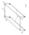
- the drive units 12 are mounted at such distances from each other that if one or even several drive units fail, under the smallest container there are still so many drive units that the further transport remains guaranteed (see Figure 4 and Figure 5).
Landscapes
- Engineering & Computer Science (AREA)
- Mechanical Engineering (AREA)
- Chemical & Material Sciences (AREA)
- Combustion & Propulsion (AREA)
- Transportation (AREA)
- Warehouses Or Storage Devices (AREA)
- Glass Compositions (AREA)
- Input Circuits Of Receivers And Coupling Of Receivers And Audio Equipment (AREA)
- Rollers For Roller Conveyors For Transfer (AREA)
- Auxiliary Devices For And Details Of Packaging Control (AREA)
- Crystals, And After-Treatments Of Crystals (AREA)
- Ship Loading And Unloading (AREA)
- Supplying Of Containers To The Packaging Station (AREA)
- Specific Conveyance Elements (AREA)
Abstract
Description
Die voliegende Erfindung bezieht sich auf Warentransport, insbesondere auf ein Verfahren und eine Vorrichtung zur Beförderung von Containern.The present invention relates to transportation of goods, and more particularly to a method and apparatus for transporting containers.
Europa wächst und wächst und wächst. Der Warentransport dadurch auch und zwar in ungeheuren Mengen. Dadurch wird fortwährend nach neuen Transportmethoden geforscht und es bestehen auch schon sehr viele Pläne und Vorschläge zur Lösung dieses schwierigen Themas. Der jetzige Stand des Warentransports auf Europas Autobahnen sitzt in einer Sackgasse. Das Verbreitern der Autobahnen kann nicht ins Unendliche ausgeführt werden und kostet Unmengen an Geld. Damit wäre das Problem trotzdem nicht gelöst, so dass es tatsächlich angebracht ist nach anderen Methoden zu suchen. Hieran haben wir uns auch beteiligt, mit folgenden drei Überlegungen:
- 1) Aus dem Bedarf heraus, Umweltfreundliche Energie einsetzen zu können, anstatt der ungeheuren Mengen an Dieseltreibstoff für den Warentransport auf den Autobahnen.
- 2) Um die immer problematischer werdenden, schwerfälligen Fernlaster so weit wie möglich von den Autobahnen zu entfernen.
- 3) Damit die Waren sicher, viel schneller umweltfreundlicher und billiger ans Ziel kommen.
- 1) Out of the need to use green energy, rather than the vast quantities of diesel fuel used to transport goods on the highways.
- 2) To remove the increasingly problematic, cumbersome long-distance trucks as far as possible from the highways.
- 3) So that the goods arrive safely, much faster and more environmentally friendly and cheaper.
Die der vorliegenden Erfindung zugrunde liegende Aufgabe besteht darin, eine Lösung zu den hier oben angeführten Problemen anzubieten.
Die Erfindung besteht aus einem Verfahren zur Beförderung von Containern gemäß dem Anspruch 1 sowie einer Förderanlage gemäß dem Anspruch 9.
Die Containerbahn wurde erfunden, zur meistmöglichen Entfernung der immer problematischer werdenden Fernlaster von den Autobahnen. Die Erfindung soll einen reibungslosen, sicheren und schnellen Transport der Waren, ausschliesslich mit Containern tätigen.
Das Ganze beruht auf einer neuartigen Konstruktion die sowohl über die Autobahn, als auch selbständig über neues Gelände errichtet werden kann. Führt sie über neues Gelände, dann kann die Strecke möglichst günstig geführt werden, da diese ja im Gegensatz zur Autobahn noch festzulegen ist. Die Konstruktion besteht aus einer überdachten und mit Seitenwänden versehenen Strecke (Hallenartig), in der sich die Bahn befindet, welche sowohl auf Beton- als auch auf Stahlunterlagen montiert werden kann. Führt sie über die Autobahn, dann wird sie logischerweise auf Tragestützen gebaut und zwar mit ihrem unteren Ende so hoch, dass auf der Autobahn unter ihr, trotzdem immer noch Fernlaster und Busse fahren können. Andernfalls kann sie auf die gleiche Art, auf Pfeilern je nach Bedarf und Möglichkeit errichtet werden, oder ganz einfach mit ihrer Tragfläche auf die Erdoberfläche.
Die Containerbahn ist eine neuartige Transportform für Container. Sie besteht aus einer mit Rädern (Rollen) bestückten Konstruktion, auf denen die Container fortbewegt werden, anstatt mit Fernlastern. Sie kann auf ihrer ganzen Länge in einer Art Halle untergebracht werden, welche vollständig mit Solarzellen belegt ist, sowohl das Dach als auch die Seitenwänden und kann so ihren Strombedarf selbst produzieren. Gleichzeitig wäre sie somit total vor sämtlichen äusseren Einflüsse abgeschirmt, wie z.B. Witterung und Unbefugten. Zur Stromversorgung der Containerkühlaggregate werden diese eventuell mit hochklappbaren Stromabnehmern (oder ähnliches) ausgestattet indem sie den Strom z.B. aus einer Stromleitung beziehen. Diese kann unter dem Dach auf einer Höhe angebracht werden die es mindestens erlaubt, "High-Cube"-Container (mit einer Höhe von 2,90m) darunter transportieren zu können. Diese Leitung kann aber auch anderswo, z.B. seitwärts angebracht werden. Wird mit den vielen Solarzellen Strom in Überfluss erzeugt, dann kann man diesen ins öffentliche Netz einspeisen, oder gegebenenfalls bei Bedarf wieder dem Netz entnehmen. Der Transport kann ununterbrochen vom Start- bis zum Zielort verlaufen, Tag und Nacht, ohne Rücksicht auf Feiertage und Witterung. Am Zielort angelangt, werden die Container z.B. über die Strasse zum Kunden gebracht und umgekehrt vom Kunden zur Containerbahn. Durch das Überdecken kann man sämtliches Niederschlagswasser auffangen und da es nicht verschmutzt und Streusalzfrei ist, in den öffentlichen Wasserhaushalt einspeisen. Der Warentransport mit Fernlastern sollte anfangs auf langen Strecken (und später nach Bedarf Etappenweise auch auf kürzeren Strecken) in die Containerbahn verlegt werden und von den Autobahnen, so weit wie möglich verschwinden.
Anstatt die Containerbahn über die Autobahn zu konstruieren, könnte man sie auch eigenständig über Land führen. Dies hätte dann den Verbrauch von zusätzlichem Land als Nachteil. Dadurch dass sie beliebig über ungenutztes Brachland geführt werden kann, würden aber die Vorteile dies grosszügig übertreffen, denn sie könnte im Gegenteil zur Autobahn viel gerader geführt und dadurch kürzer werden. Da sie weder angemessene Steigungen noch Gefälle oder Unwetter zu fürchten braucht, kann sie fast beliebig Berge und Bergketten empor und hinunterfahren, oder an den Hängen entlang umfahren und braucht so deutlich weniger Tunnels oder hohe Brücken. Das Bauverfahren wäre in diesem Fall auch einfacher.The object underlying the present invention is to provide a solution to the above-mentioned problems.
The invention consists of a method for transporting containers according to
The container train was invented, for the most possible removal of increasingly problematic long-distance trucks from the highways. The invention is intended to ensure a smooth, safe and fast transport of the goods, exclusively with containers.
The whole thing is based on a novel construction that can be built both on the highway, as well as independently on new terrain. If it leads over new terrain, then the route can be conducted as cheaply as possible, since this is still to be determined in contrast to the motorway. The construction consists of a covered and with side walls provided route (hall-like), in which the track is, which can be mounted on both concrete and steel pads. Take them over the highway, then, logically, it will be built on support columns, with its lower end so high that it will still be able to drive on the highway below, but still have long-distance trucks and buses. Otherwise, it can be built in the same way, on pillars as needed and opportunity, or simply with its wing on the surface of the earth.
The container track is a novel form of transport for containers. It consists of a construction equipped with wheels (rollers), on which the containers are moved, rather than with remote trucks. It can be housed along its entire length in a kind of hall, which is completely covered with solar cells, both the roof and the side walls and can thus produce their own power requirements. At the same time, it would thus be totally shielded from all external influences, such as weather and unauthorized persons. For the power supply of the container cooling units, these may be equipped with flip-up pantographs (or similar) by drawing the power eg from a power line. This can be mounted under the roof at a height that allows at least "high-cube" container (with a height of 2.90m) to transport underneath. But this line can also elsewhere, for example, be mounted sideways. If electricity is generated in abundance with the many solar cells, then you can feed it into the public grid, or, if necessary, remove it again from the grid. The transport can run uninterrupted from the start to the destination, day and night, regardless of holidays and weather. Arrived at the destination, the containers are brought to the customer via the road, for example, and vice versa from the customer to the container train. By covering you can catch all of the rainwater and because it is not polluted and free from de-icing salt, feed into the public water balance. The transport of goods by long distance truck was initially to be laid on long routes (and later, as required, in stages also on shorter routes) into the container railway and disappear from the motorways as far as possible.
Instead of constructing the container train on the highway, you could also lead them independently on land. This would then have the consumption of additional land as a disadvantage. The fact that they can be arbitrarily carried over unused fallow land, but the benefits would exceed this generously, because they could be the opposite to the highway much straighter out and thus shorter. Since it does not need to be afraid of any gradients, inclines or inclement weather, it can travel up and down almost any mountain or mountain range, or drive around along the slopes, and thus need significantly fewer tunnels or high bridges. The construction process would also be easier in this case.
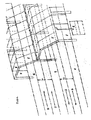
- Bild 1 zeigt eine bevorzugte Anordnung der Containerbahn.Figure 1 shows a preferred arrangement of the container track.
- Bild 2 zeigt Konstruktionsdetails der Containerbahn.Figure 2 shows construction details of the container track.
- Bild 2A ist eine Draufsicht eines Teils der Containerbahn.Figure 2A is a plan view of part of the container track.
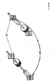
- Bild 3 stellt zwei Antriebseinheiten dar und zeigt, wie sie austauschbar sind.Figure 3 shows two drive units and how they are interchangeable.
- Bild 4 zeigt, wie die Antriebseinheiten an dem Rahmen der Containerbahn angebracht sind.Figure 4 shows how the drive units are attached to the frame of the container track.
- Bild 5 zeigt das Funktionsprinzip der Containerbahn.Figure 5 shows the functional principle of the container track.
-
Bild 6 zeigt weitere Details der Containerbahn.
Picture 6 shows further details of the container track. - Bild 7 zeigt eine Platform, auf der ein Container zu transportieren ist.Figure 7 shows a platform on which a container is to be transported.
Das prinzip der "Containerbahn"
Die Containerbahn besteht aus zwei nebeneinanderlaufenden Fahrspuren welche in die eine Richtung laufen und zwei Weitere welche parallel zu diesen in entgegengesetzte Richtung führen, genau wie die Autobahn. Diese Doppelstränge dienen ausschliesslich zur Beförderung von Containern. Da sich auf jedem Doppelstrang die linke Spur (in Fahrtrichtung) am äusseren Rand der Containerbahn befindet, würde diese sich am besten als Lauf-, Auf- und Ausfahrtspur eignen. Die rechte Spur hingegen, dient dann in diesem Fall nur als Überhol- und Ausweichspur bei Bedarf, z.B. bei eventuellen grösseren Reparaturen. Über die Mittelstreifen und die Ausweichstreifen der Autobahn werden diese Flächen entlang der Containerbahn als Fahrwege der Unterhaltsmannschaften genutzt. Neben den äusseren Fahrwege werden Werkstätten errichtet und damit die Ersatzteile nicht zu weit transportiert werden müssen, kommen in angemessenen Abständen die Ersatzteillager.The principle of the "container track"
The container track consists of two adjacent lanes running in one direction and two more which run parallel to these in the opposite direction, just like the highway. These double strands serve exclusively for the transport of containers. Since the left lane (in the direction of travel) is located on the outer edge of the container track on each double strand, it would be best suited as a runway, exit lane and exit lane. The right-hand lane, on the other hand, only serves as an overtaking and avoidance lane when needed, eg in case of major repairs. Via the median strips and the evasion strips of the motorway, these areas along the container track are used as routes for maintenance crews. In addition to the outer driveways workshops are built and so that the spare parts need not be transported too far, come at reasonable intervals, the spare parts warehouse.
Wie funktioniert die "Containerbahn" ?
Mit der Containerbahn stellen wir den Transport der Container praktisch auf den Kopf.
Das heisst: bislang wurden die Container über den Aufleger auf die Räder des Lastwagens durch dessen eigenen Motor befördert, indem die Lkw-Räder über die Strasse liefen. Die Container kommen nämlich anfangs auf Plattformen, an denen sie durch Drehverriegelungen (Twist-locks) befestigt sind und laufen über die feststehenden, sich drehenden Räder (Rollen) und somit haben wir, wie schon erwähnt, das Prinzip auf den Kopf gestellt. Danach sollten beim Bau von neuen Containern und im Laufe der Zeit auch die schon existierenden noch brauchbaren, nach und nach mit Laufflächen und Führungsflanken versehen werden und die Plattformen können dann nach und nach wieder aus dem Verkehr geholt werden. Für die Spurenhaltung der Container sorgen z.B. seitlich angebrachte Führungsrollen. Das viele überflüssige Mehrgewicht des Lastwagens musste stets und überall mitgeschleppt werden, was eine enorme Verschwendung an Material (Verschleiss) und vor allem von Kraftstoff mit sich brachte. Die Containerbahn dagegen ist sozusagen ein Gemeinschaftstransportmittel und trotzdem läuft jeder einzelne Container computergesteuert selbständig sein Ziel unaufhaltsam an. Mit ihr wird nur der Container transportiert und zwar ohne Treibstoff, sondern mit dem selbstproduzierten, oder (bei Bedarf) vom Netz entnommenen Strom. Der Verschleiss fällt natürlich auf die mechanischen, elektrischen und elektronischen Einrichtungen zurück, aber halten sich hier in Grenzen, unter anderem weil alle Austauchelemente standardisiert sind und das Ganze nicht den Witterungseinflüssen ausgesetzt ist. Auch fallen die Ausfallzeiten der Fernlaster während der Reparatur- und Wartungszeiten aus. Durch die Standardisierung gestaltet sich der Unterhalt viel einfacher als bei den Fernlastern, weil immer nur die gleichen Teile ausgetauscht werden, die schon überholt (gewartet) auf Lager auf ihren Einsatz (Austausch) mit wenigen Handgriffen warten. Unser Hauptanliegen besteht darin, dass wir einen möglichst unbehinderten kontinuirlichen Materialfluss erreichen wollen. Dies ist eine der wichtigsten Aufgaben der Containerbahn und zwar mit einem Höchstmass an Sicherheit. Deshalb müssen die Fahrspuren (Transportstränge) absolut menschenleer sein und nur bei Unfällen oder Reparaturarbeiten von den jeweiligen Mannschaften betreten werden, während der Transport auf diesem Streckenabschnitt auf der anderen Spur weiterläuft. Jedes Antriebsrad hat z.B. seinen eigenen Elektromotor und bildet so eine komplette Antriebseinheit. Diese Antriebseinheiten sind so angeordnet, dass wenn ein oder mehrere Elektromotoren oder Antriebsräder ausfallen, sich immer noch genügend intakte Antriebseinheiten unter dem kleinsten Container befinden, um ihn weiterzubefördern. Die defekte Antriebseinheit oder -einheiten werden dann kurzerhand entfernt und durch andere schon bereitstehende und in der Werkstatt überholte ersetzt. Diese und alle anderen anfallenden Wartungsarbeiten können problemlos ausgeführt werden, währenddem der Containertransport unbehelligt über die zweite Spur weiterläuft.How does the "container track" work?
With the container track we make the transport of the containers practically upside down.
This means that so far the containers were transported via the trailer to the wheels of the truck by its own engine by the truck wheels ran on the road. The containers come initially on platforms to which they are attached by twist locks (locks) and run over the fixed, rotating wheels (rollers) and thus we have, as already mentioned, the principle turned upside down. Thereafter, the construction of new containers and in the course of time, the already existing still usable, should gradually be provided with treads and leading edges and the platforms can then gradually be brought back from the market. For keeping track of the containers provide, for example, laterally mounted guide rollers. The many unnecessary extra weight of the truck had to be carried always and everywhere, which is a huge waste of material (wear) and especially of fuel with it brought. The container train, on the other hand, is, so to speak, a common means of transport, and yet every single container runs independently and independently, its destination inexorably. With it, only the container is transported and without fuel, but with the self-produced, or (if necessary) taken from the grid current. Of course, the wear is attributable to the mechanical, electrical and electronic devices, but they are limited here, among other things because all the replacement elements are standardized and the whole is not exposed to the effects of the weather. Also, the downtime of the long-distance trucks during the repair and maintenance times. Due to the standardization, the maintenance is much easier than with the remote, because only the same parts are replaced, the already obsolete (waiting) in stock to wait for their use (replacement) with a few simple steps. Our main concern is that we want to achieve the most unimpeded continuous flow of material possible. This is one of the most important tasks of the container train with the highest level of safety. Therefore, the lanes (transport strands) must be absolutely deserted and only in case of accidents or repairs by the respective teams to be entered, while the transport continues on this section on the other lane. Each drive wheel has, for example, its own electric motor and thus forms a complete drive unit. These drive units are arranged so that when one or more electric motors or drive wheels fail, there are still enough intact drive units under the smallest container to convey it. The defective drive unit or units are then removed without further ado and replaced by other already available and overhauled in the workshop. These and all other maintenance work can be carried out without problems while the container transport continues unobstructed on the second lane.
Der Antrieb der "Containerbahn".
Die Antriebseinheiten der Containerbahn sind (wie im vorigen Artikel schon erwähnt) so angebracht, dass bei Ausfall von einer oder mehreren Antriebseinheiten gleichzeitig, sich unter dem kleinsten Container immer noch genügend funktionsfähige Antriebseinheiten befinden, um den Weitertransport zu gewährleisten. Die Antriebseinheiten werden nur bei Bedarf eingeschaltet. Ist kein Container in Anfahrt, dann stehen sie still. Nähert sich ein Container einer Antriebseinheit bis auf eine bestimmte Nähe, dann schaltet diese sich ein um schon in Fahrt zu sein, wenn der Container sie erreicht. Hat er sie mit seinem hinteren Ende überfahren, dann schaltet sie wieder ab und wartet auf den nächsten Einschaltbefehl. Dann die nächste Antriebseinheit und so weiter. Kommen die Container dicht genug hintereinander herangefahren, dann laufen die Antriebseinheiten ununterbrochen weiter. Da der ganze Versandprozess computergesteuert ist, werden die Weichen automatisch gestellt. Der Container ist intern jederzeit identifizierbar, nach aussen in höchstem Mass geschützt und kann während seiner Fahrt fortwährend verfolgt werden.The drive of the "container track".
The drive units of the container track are (as mentioned in the previous article) mounted so that in case of failure of one or more drive units at the same time, under the smallest container still enough functional drive units are to ensure the further transport. The drive units are only switched on when needed. If no container is approaching, then they stand still. If a container of a drive unit approaches a certain proximity, then it switches on to be in motion when the container reaches it. If he has run over it with his rear end, then it switches off again and waits for the next switch-on command. Then the next drive unit and so on. If the containers come close enough in succession, the drive units continue to run uninterrupted. Since the entire shipping process is computer-controlled, the points are set automatically. The container is internally identifiable at all times, externally protected to the highest degree and can be continuously tracked during its journey.
Die konstruktion der "Containerbahn".
Führt die Containerbahn über die Autobahn, dann wird letztere dadurch nicht beeinträchtigt und sie bleibt voll funktionsfähig bestehen. Später wird sich feststellen lassen, ob man sie stellenweise zu Kosteneinsparungen zurückbauen kann, anstatt sie gemäss den heutigen immer wiederkehrenden Forderungen, wegen der kontinuierlichen Zunahme der Fernlaster sehr kostspielig zu verbreitern. Die Containerbahn ist dazu bestimmt soviel Fracht wie möglich von der Autobahn zu nehmen und das kann sie durchaus, denn sie hat ein enormes Aufnahmepotential, da die Container bei Bedarf, ähnlich wie die Wagen eines Zuges hintereinander laufen können ohne miteinander verbunden zu sein. Mittelstreifen und Seitenränder der Autobahn können zum einpflanzen der Stützpfeiler für die Containerbahn dienen, so dass keine weitere Oberfläche benötigt wird, abgesehen von Stellen an denen das Überfahren der Autobahn nicht möglich ist, wie z.B. Tunnels oder hohe Brücken. Bei Tunnels kann sie das Hindernis um- oder überfahren und bei hohe Brücken kann sie ins Tal hinunter und auf der anderen Seite wieder hoch fahren, um danach wieder über die Autobahn zu gelangen. Die Pfeiler und die Tragkonstruktion können nach Möglichkeit und Bedarf entweder aus Stahl (Stahlträger, Stahlplatten u.s.w.) oder aus Stahlbeton, oder anderen geeigneten Materialien errichtet werden. Die Pfeiler, die zu beiden Seiten und dem Mittelstreifen der Autobahn aus dem Boden herauswachsen, laufen weiter in die Höhe, bis sie sich am oberen Ende z.B. durch eine gewisse Schrägstellung miteinander verbinden. Dadurch bilden sie eine solide Einheit und indem diese Einheiten miteinander verbunden werden, dienen sie gleichzeitig als Dachauflage und Wandverkleidung. Das Dach und die gesamten Seitenflächen werden (soweit das möglich und erwünscht ist) ganz z.B. mit Hallenblechen verkleidet, an denen dann die Solarzellen angebracht werden können. An jedem mit Containern zu beliefernden Schwerpunkt werden Containerausfahrten errichtet, mit anschliessendem Auffang- bzw. Ab- und Aufladeplatz. Von hier aus werden die Container zum und vom Kunden gebracht. An jeder Abfahrtsrampe steht (so wie auf den Schiffcontainerhäfen) eine Röntgenanlage und jeder Container muss sie zur Vorsichtsmassnahme und zur Warenkontrolle vor seiner Reise durchfahren.The construction of the "container track".
If the container track passes over the motorway, then the latter will not be affected and it will remain fully functional. Later, it will be possible to determine if they can be scaled back in some ways to cost savings, rather than being very costly, in line with today's recurring demands, because of the continuous increase in long-distance lorries. The container track is designed to take as much cargo as possible off the freeway and she can, because she has a huge uptake potential, since the container when needed, similar to the cars of a train can run behind each other without being connected. Median strips and side edges of the highway can be used for planting the pillars for the container track, so that no further surface is needed, except for places where the highway is not possible, such as tunnels or high bridges. In tunnels she can drive around or over the obstacle and high bridges can go down to the valley and up the other side to get back on the highway. The pillars and the supporting structure can, if possible and required, be constructed either from steel (steel beams, steel plates, etc.) or reinforced concrete, or other suitable materials. The pillars, which grow out of the ground on both sides and the median strip of the motorway, continue to run upwards until they connect with each other at the upper end, for example by a certain inclination. As a result, they form a solid unit and by connecting these units together, they simultaneously serve as a roof covering and wall cladding. The roof and the entire side surfaces are (as far as this is possible and desirable) completely covered with hall panels, for example, on which then the solar cells can be attached. Container exits are set up at each center of gravity to be supplied with containers, with subsequent collection and unloading and loading points. From here the containers are brought to and from the customer. At each departure ramp (as well as at the shipping container ports) there is an x-ray system and every container must be passed through for precaution and physical checks prior to its journey.
Bild 1
Die Containerbahn besteht genau wie die Autobahn aus den zwei Doppelsträngen 1. Sie führen in entgegengesetzten Richtungen. Auf jedem Doppelstrang ist je eine Fahrspur 2 und eine Überholspur 3. An der Stelle des Mittelstreifens und der beiden Ausweichspuren der Autobahn, befinden sich auf der Containerbahn Wartungswege 4. Während die äusseren Wartungswege 4 zur Bedienung der äusseren Fahrspuren 2 dienen, ist der Mittlere zur Betreuung der beiden Überholspuren 3 bestimmt. Auf der Überdachung sowie an den Seitenwänden sind Solarzellen 5 angebracht, woraus die Containerbahn ihren Strom bezieht. Das Niederschlagswasser wird z B in unterirdischen Auffangbecken 6 gesammelt, welche sich aussen neben der Bahn in regelmässigen Abständen befinden und von hier aus weitergeleitet wird, oder direkt dem öffentlichen Wasserhaushalt zugeführt wird.
The container track is just like the highway from the two
Bilder 2-7
Die Bahn selbst besteht aus zwei T-förmigen (oder ähnlichen) miteinander verbundenen parallellaufenden Stahlträgersträngen 1, bestehend aus einzelnen durch Verbindungsplatten 1A (Bild 2A) aneinander verschraubten Segmenten, welche auf dem Tragkörper mit Verankerungsschrauben 2 befestigt sind und durch auswechselbare Abstandhalter 3 (nicht starr, zum Austausch beider) miteinander verbunden sind. In den Stahlträgern befinden sich von oben nach unten, Einschnitte 4 für die Einschiebeplatten 5 mit Lager 6, welche von den auf den Stahlträgern verschweissten (oder anders befestigten) Halterungsplatten 8 (siehe Schweissnaht 7) in Position gehalten werden. Durch die Lager hindurch läuft eine Achse 9, auf der ein Antriebsrad 10 und ein Elektromotor 11 montiert sind. Der Elektromotor 11 ist an der diesseitigen Einschiebeplatte 5 befestigt. So bildet das Ganze eine kompakte Antriebseinheit 12, welche sowohl rechtsseitig als auch linksseitig in die Einschnitte eingeschoben werden kann (siehe hierzu auch Bild 3). Auf den Stahlträgern sind Führungsrollen 13 zur Spurenführung der Container angebracht, welche auf den Halterungen 14 montiert sind. Auf die von den Elektromotoren 11 angetriebenen Antriebsräder 10 kommen die Plattformen 15 (Bild 7), auf denen sich die Container befinden, welche mit Drehverriegelungen (Twistlocks) an die Halterungen (corner-castings)16 (Bild 7) befestigt sind und von diesen Antriebsrädern fortbewegt werden. An den Seitenwänden 17 der Plattformen 15 laufen die Führungsrollen 14 zur Spurenführung. Die Plattformen haben eine Länge die den Containern der Norm TEU (20 Fußcontainer) entspricht und sind mit 8 corner-castings 16 versehen, damit man die Plattformen selbst zu zwei aneinander befestigen kann um so die FEU (40 Fußcontainer) transportieren zu können und die Containern daran zu befestigen. Die Antriebseinheiten 12 sind in solchen Abständen voneinander angebracht, dass sich bei Ausfall von einer oder auch gleichzeitig mehrerer Antriebseinheiten, unter dem kleinsten Container immer noch so viele Antriebseinheiten befinden, dass der Weitertransport garantiert bleibt (siehe Bild 4 und Bild 5).Pictures 2-7
The track itself consists of two T-shaped (or similar) interconnected parallel running
Erklärung der Bezugszeichen auf den Bildern.Explanation of the reference numbers in the pictures.
- 1.1.
- Doppelstrangdouble strand
- 2.Second
- Fahrspurlane
- 3.Third
- Überholspuroutside lane
- 4.4th
- Wartungswegemaintenance ways
- 5.5th
- Solarzellensolar cells
- 6.6th
- Auffangbeckencatch basin
- 1.1.
- T-förmige StahlträgerT-shaped steel beams
- 1A.1A.
- VerbindugsplattenVerbindugsplatten
- 2.Second
- Verankerungsschraubenanchoring screws
- 3.Third
- Abstandshalterspacer
- 4.4th
- Einschnittecuts
- 5.5th
- Einschiebeplatten mit LagerSlide-in plates with bearings
- 6.6th
- Lagercamp
- 7.7th
- SchweissnahtWeld
- 8.8th.
- Aufgeschweisste HalterungsplattenWelded mounting plates
- 9.9th
- Achseaxis
- 10.10th
- Antriebsraddrive wheel
- 11.11th
- Elektromotor an der inneren Seite der Einschiebeplatte befestigtElectric motor attached to the inner side of the slide-in plate
- 12.12th
- Beidseitig austauschbare AntriebseinheitDouble-sided replaceable drive unit
- 13.13th
- Führungsrollenguide rollers
- 14.14th
- FührungsrollenhalterungenBlock mounts
- 15.15th
- Plattformplatform
- 16.16th
- Halterungen (corner-castings)Brackets (corner castings)
- 17.17th
- Seitenwände als Laufflächen für die FührungsrollenSidewalls as running surfaces for the guide rollers
Claims (20)
mindestens ein Container auf drehende Antriebseinheiten (12) einer Förderanlage gefahren wird,
dadurch gekennzeichnet, dass
die Förderanlage auf einer langen Strecke aufgebaut wird, damit die Fernbeförderung von Containern mindestens regionalweit ermöglicht wird.Method of transporting containers, wherein
at least one container is driven on rotating drive units (12) of a conveyor system,
characterized in that
the conveyor system is set up on a long route to enable the long-distance transport of containers at least regionally.
die Spur der Container durch an der Förderanlage befestigte Führungsrollen (13) geführt wird.A method according to claim 1, wherein
the track of the container is guided by guide rollers (13) fastened to the conveyor system.
die Förderanlage überdeckt ist und gegebenenfalls mit Seitenwänden hallenartig versehen ist.Method according to one of the preceding claims, wherein
the conveyor system is covered and optionally provided with side walls like a hall.
mindestens ein Container über Stromabnehmer, die gegen am Dach oder seitwärts angebrachte elektrische Leitungen gleiten, mit Strom versorgt wird.Method according to one of the preceding claims, wherein
at least one container is powered by pantographs sliding against the roof or sideways mounted electrical wiring.
die Antriebseinheiten (12) und gegebenenfalls die ganze Anlage durch Solarzellen mit Strom versorgt werden.Method according to one of the preceding claims, wherein
the drive units (12) and possibly the whole system are powered by solar cells with electricity.
die Fernbeförderung auf zwei nebeneinanderlaufenden Spuren, vorzugsweise in beiden Richtungen erfolgt.Method according to one of the preceding claims, wherein
the long distance transport takes place on two adjacent tracks, preferably in both directions.
mindestens eine der Antriebseinheiten (12) durch einen herannahenden Container eingeschaltet wird und vorzugsweise durch einen sich entfernenden Container ausgeschaltet wird.Method according to one of the preceding claims, wherein
at least one of the drive units (12) is switched on by an approaching container and is preferably switched off by a container that is moving away.
der mindestens eine Container auf eine Platform (15) zur Beförderung auf die Förderanlage angebracht wird.Method according to one of the preceding claims, wherein
the at least one container is mounted on a platform (15) for transport to the conveyor.
einen langestreckten Rahmen (1,3);
mehrere drehbaren Antriebseinheiten (12), die quer am Rahmen (1,3) und parallel zueinander am Rahmen (1,3) befestigt sind und jeweils mindestens ein Antriebsrad (10) aufweisen, auf das sich ein Container stützen kann und fahren kann,
dadurch gekennzeichnet, dass
sich die Förderanlage auf einer langen Strecke erstreckt, so dass sie die Fernbeförderung von Containern mindestens regionalweit ermöglicht.Conveying conveyor for transporting containers comprising
an elongated frame (1,3);
a plurality of rotatable drive units (12) mounted transversely on the frame (1,3) and parallel to each other on the frame (1,3) and each having at least one drive wheel (10) on which a container can support and drive,
characterized in that
the conveyor extends over a long distance so that it enables the long-distance transport of containers at least regionally.
der Rahmen (1,3) einzelne vorzugsweise durch Verbindungsplatten (1A) aneinander befestigte vorzugsweise T-förmige Trägerelemente (1) und Abstandhalter (3) aufweist.Conveying system according to claim 9, wherein
the frame (1, 3) has preferably T-shaped carrier elements (1) and spacers (3), preferably fastened to one another by connecting plates (1A).
mindestens eine der Antriebseinheiten (12) mindestens zwei Lager aufweist, die als Einschiebeplatten (5) ausgeführt sind, und durch die eine Achse (9) hindurch läuft, und die Einschiebeplatten (5) in Einschnitte (4) des Rahmens (1,3) eingeschoben sind.Conveying system according to one of claims 9-11, wherein
at least one of the drive units (12) has at least two bearings, which are designed as push-in plates (5), and by the an axis (9) passes through, and the push-in plates (5) in incisions (4) of the frame (1,3) are inserted.
mindestens eine der Antriebseinheiten (12) eine Achse (9) aufweist, auf der ein Antriebsrad (10) sowie vorzugsweise ein elektrischer Motor (11) angeordnet ist, der vorzugsweise an einer der Einschiebeplatten (5) angeflanscht ist.Conveying system according to one of claims 9-12, wherein
at least one of the drive units (12) has an axis (9) on which a drive wheel (10) and preferably an electric motor (11) is arranged, which is preferably flanged to one of the push-in plates (5).
die Antriebseinheiten (12) derart ausgeführt sind, dass sie in die eine oder die um 180° umgedrehte Position eingebaut werden können.Conveying system according to claim 13, wherein
the drive units (12) are designed such that they can be installed in one or the 180 ° reversed position.
die Förderanlage überdeckt ist und gegebenenfalls mit Seitenwänden hallenartig versehen ist.Conveying system according to one of claims 9-14, wherein
the conveyor system is covered and optionally provided with side walls like a hall.
die Förderanlage Solarzellen, die vorzugsweise auf dem Dach und/oder an den Seitenwänden der Förderanlage angeordnet sind, zur Stromversorgung der Antriebseinheiten (12) aufweist.Conveying system according to one of claims 9-15, wherein
the conveyor system solar cells, which are preferably arranged on the roof and / or on the side walls of the conveyor system, for powering the drive units (12).
die Förderanlage aus zwei nebeneinanderlaufenden Fahrspuren (Bild 1: 2,3) besteht, wobei vorzugsweise die Eine in eine Richtung läuft und die Andere in die entgegengesetzte Richtung läuft.Conveying system according to one of claims 9-16, wherein
the conveyor system consists of two adjacent lanes (Figure 1: 2, 3), whereby preferably the one runs in one direction and the other runs in the opposite direction.
die Förderanlage aus zwei nebeneinanderlaufenden Fahrspuren (Bild 1: 2,3), die in eine Richtung laufen, und zwei weiteren nebeneinanderlaufenden Fahrspuren (Bild 1: 2,3), die parallel zu diesen in die entgegengesetzte Richtung laufen, besteht.Conveying system according to one of claims 9-16, wherein
The conveyor system consists of two adjacent lanes (Figure 1: 2, 3) that run in one direction and two others There are adjacent lanes (Fig. 1: 2, 3) that run in the opposite direction parallel to them.
ein Wartungsweg (Bild 1: 4) in der Mitte zwischen den zwei bzw. vier nebeneinanderlaufenden Fahrspuren (Bild 1: 2,3) und/oder an der äusseren Seite einer jeweiligen äusseren Fahrspur (Bild 1: 2) vorgesehen ist.Conveying system according to claim 17 or 18, wherein
a maintenance path (Figure 1: 4) in the middle between the two or four adjacent lanes (Figure 1: 2, 3) and / or on the outer side of a respective outer lane (Figure 1: 2) is provided.
mindestens eine der Antriebseinheiten (12) derart gesteuert ist, dass die Antriebseinheit eingeschaltet wird, wenn ein Container zur Antriebseinheit heran naht, und vorzugsweise ausgeschaltet wird, wenn sich ein Container von der Antriebseinheit entfernt.Conveying system according to one of claims 9-19, wherein
at least one of the drive units (12) is controlled so that the drive unit is turned on when a container approaches the drive unit, and is preferably turned off when a container moves away from the drive unit.
Priority Applications (13)
| Application Number | Priority Date | Filing Date | Title |
|---|---|---|---|
| DE502006001823T DE502006001823D1 (en) | 2006-01-30 | 2006-01-30 | container track |
| PL06120774T PL1826153T3 (en) | 2006-01-30 | 2006-01-30 | Container way |
| EP06120774A EP1826153B1 (en) | 2006-01-30 | 2006-01-30 | Container way |
| AT06120774T ATE411240T1 (en) | 2006-01-30 | 2006-01-30 | CONTAINER RAILWAY |
| ES06120774T ES2314838T3 (en) | 2006-01-30 | 2006-01-30 | CONTAINER VIA. |
| SI200630128T SI1826153T1 (en) | 2006-01-30 | 2006-01-30 | Container way |
| PT06120774T PT1826153E (en) | 2006-01-30 | 2006-01-30 | Container way |
| EP06101006A EP1813496A1 (en) | 2006-01-30 | 2006-01-30 | Roller way for container transport |
| US12/162,453 US8074787B2 (en) | 2006-01-30 | 2007-01-19 | Container track for container transport |
| JP2008551765A JP2009525236A (en) | 2006-01-30 | 2007-01-19 | Container transportation route |
| PCT/EP2007/050556 WO2007085571A2 (en) | 2006-01-30 | 2007-01-19 | Container track for container transport |
| CN2007800039828A CN101374712B (en) | 2006-01-30 | 2007-01-19 | Roller way for container transport |
| EA200801581A EA014259B1 (en) | 2006-01-30 | 2007-01-19 | Conveying system for container transport |
Applications Claiming Priority (1)
| Application Number | Priority Date | Filing Date | Title |
|---|---|---|---|
| EP06101006A EP1813496A1 (en) | 2006-01-30 | 2006-01-30 | Roller way for container transport |
Related Child Applications (1)
| Application Number | Title | Priority Date | Filing Date |
|---|---|---|---|
| EP06120774A Division EP1826153B1 (en) | 2006-01-30 | 2006-01-30 | Container way |
Publications (1)
| Publication Number | Publication Date |
|---|---|
| EP1813496A1 true EP1813496A1 (en) | 2007-08-01 |
Family
ID=36581598
Family Applications (2)
| Application Number | Title | Priority Date | Filing Date |
|---|---|---|---|
| EP06101006A Withdrawn EP1813496A1 (en) | 2006-01-30 | 2006-01-30 | Roller way for container transport |
| EP06120774A Active EP1826153B1 (en) | 2006-01-30 | 2006-01-30 | Container way |
Family Applications After (1)
| Application Number | Title | Priority Date | Filing Date |
|---|---|---|---|
| EP06120774A Active EP1826153B1 (en) | 2006-01-30 | 2006-01-30 | Container way |
Country Status (12)
| Country | Link |
|---|---|
| US (1) | US8074787B2 (en) |
| EP (2) | EP1813496A1 (en) |
| JP (1) | JP2009525236A (en) |
| CN (1) | CN101374712B (en) |
| AT (1) | ATE411240T1 (en) |
| DE (1) | DE502006001823D1 (en) |
| EA (1) | EA014259B1 (en) |
| ES (1) | ES2314838T3 (en) |
| PL (1) | PL1826153T3 (en) |
| PT (1) | PT1826153E (en) |
| SI (1) | SI1826153T1 (en) |
| WO (1) | WO2007085571A2 (en) |
Families Citing this family (5)
| Publication number | Priority date | Publication date | Assignee | Title |
|---|---|---|---|---|
| KR101162692B1 (en) | 2010-02-19 | 2012-07-05 | 김동원 | Long Distance Auto Transference System |
| CN101973274A (en) * | 2010-11-05 | 2011-02-16 | 张元庆 | Carrying device, urban public transport system and operation method thereof |
| US10239702B2 (en) * | 2017-01-06 | 2019-03-26 | Roach Manufacturing Corporation | Tubular mezzanine and conveyor support structures and stiffener brackets for assembly thereof |
| WO2019210935A1 (en) * | 2018-04-30 | 2019-11-07 | Cargo Sous Terrain Ag | Transport, storage and sequencing system for goods |
| FR3093509B1 (en) * | 2019-03-06 | 2021-04-23 | Rene Brunone | Distributed motorized belt conveyor, and associated material transport method |
Citations (2)
| Publication number | Priority date | Publication date | Assignee | Title |
|---|---|---|---|---|
| US3735710A (en) * | 1971-03-01 | 1973-05-29 | J Hickman | Transportation system |
| US3903807A (en) * | 1973-01-12 | 1975-09-09 | Averette T Lee | Mass rapid system |
Family Cites Families (24)
| Publication number | Priority date | Publication date | Assignee | Title |
|---|---|---|---|---|
| US283947A (en) * | 1883-08-28 | Railway and car | ||
| US1198605A (en) * | 1916-02-15 | 1916-09-19 | Walter E Trent | System of transportation. |
| NL7408031A (en) * | 1973-08-27 | 1975-03-03 | Masyc Ag | ASSORTMENT, GROUP OR SET OF CONSTRUCTION ELEMENTS FOR THE MANUFACTURE OF TRANSPORT EQUIPMENT. |
| SU1479340A1 (en) * | 1982-07-19 | 1989-05-15 | Т. П. Губасар н и Л. А. Губасар н | Transport system |
| US5048670A (en) * | 1991-03-11 | 1991-09-17 | Crafton James W | Flexible conveyor assembly and conveying apparatus and method for lifting fluid |
| NL9300926A (en) * | 1993-05-28 | 1994-12-16 | Hollandia Ind Mij Nv | Transport device and method for transporting containers along a guideway. |
| US5348137A (en) * | 1993-11-09 | 1994-09-20 | Palmer R Gary | Vertical tensioning and anti-rotational device for use with single continuous rope conveyor lifting system |
| IT1283408B1 (en) * | 1996-07-08 | 1998-04-21 | Alcatel Italia | METHOD AND AUTOMATIC SYSTEM FOR THE TIMING OF OBJECTS WITH PLANAR SUPPORT BASE |
| EP0834459B1 (en) * | 1996-10-04 | 2003-08-27 | Noell Crane Systems GmbH | Container transport system with rails |
| DE19725945A1 (en) * | 1997-06-19 | 1998-12-24 | Rolf Hoericht | Electrical energy generator using solar modules, e.g. for electric railway |
| US6098789A (en) * | 1998-05-11 | 2000-08-08 | Alvey Systems, Inc. | Conveyor operation control system |
| JP2001106331A (en) * | 1999-10-08 | 2001-04-17 | Kyowa Seisakusho:Kk | Carrying control system |
| AT412965B (en) * | 2001-09-20 | 2005-09-26 | Innova Patent Gmbh | CONVEYOR |
| US7280889B2 (en) * | 2002-03-08 | 2007-10-09 | Humphrey Products Company | Networkable zone control modules and method and coveyor system incorporating the same |
| US6820736B2 (en) * | 2002-05-08 | 2004-11-23 | Itoh Denki Co., Ltd. | Conveying apparatus |
| AT413027B (en) * | 2002-06-14 | 2005-10-15 | Tgw Transportgeraete Gmbh | ROLLER ARRANGEMENT FOR A ROLLER CONVEYOR |
| US7104395B2 (en) * | 2002-11-05 | 2006-09-12 | Lockheed Martin Corporation | Control and power distribution system for a conveyor |
| US6860381B2 (en) * | 2003-01-29 | 2005-03-01 | Hytrol Conveyor Company, Inc. | Decentralized drive system for a conveyor |
| JP3799404B2 (en) * | 2003-08-25 | 2006-07-19 | 伊東電機株式会社 | Zone-controlled conveyor system and zone controller |
| US6907978B2 (en) * | 2003-10-09 | 2005-06-21 | Lockheed Martin Corporation | Methods and apparatuses for inducting articles onto a conveyor |
| DE10353455B4 (en) * | 2003-11-15 | 2007-07-05 | Noell Mobile Systems & Cranes Gmbh | Rail-guided transport system for containers |
| US7243781B2 (en) * | 2005-06-22 | 2007-07-17 | Hytrol Conveyor Company, Inc. | Conveyor loading zone system and method |
| DE102006005978A1 (en) * | 2006-02-08 | 2007-08-16 | Eisenmann Anlagenbau Gmbh & Co. Kg | Roller conveyors |
| US7681326B2 (en) * | 2006-06-25 | 2010-03-23 | Marusho-Giken Co., Ltd. | All weather passive-type solar Ogako drying house |
-
2006
- 2006-01-30 DE DE502006001823T patent/DE502006001823D1/en active Active
- 2006-01-30 SI SI200630128T patent/SI1826153T1/en unknown
- 2006-01-30 ES ES06120774T patent/ES2314838T3/en active Active
- 2006-01-30 PT PT06120774T patent/PT1826153E/en unknown
- 2006-01-30 PL PL06120774T patent/PL1826153T3/en unknown
- 2006-01-30 EP EP06101006A patent/EP1813496A1/en not_active Withdrawn
- 2006-01-30 EP EP06120774A patent/EP1826153B1/en active Active
- 2006-01-30 AT AT06120774T patent/ATE411240T1/en active
-
2007
- 2007-01-19 EA EA200801581A patent/EA014259B1/en not_active IP Right Cessation
- 2007-01-19 WO PCT/EP2007/050556 patent/WO2007085571A2/en active Application Filing
- 2007-01-19 JP JP2008551765A patent/JP2009525236A/en active Pending
- 2007-01-19 US US12/162,453 patent/US8074787B2/en not_active Expired - Fee Related
- 2007-01-19 CN CN2007800039828A patent/CN101374712B/en not_active Expired - Fee Related
Patent Citations (2)
| Publication number | Priority date | Publication date | Assignee | Title |
|---|---|---|---|---|
| US3735710A (en) * | 1971-03-01 | 1973-05-29 | J Hickman | Transportation system |
| US3903807A (en) * | 1973-01-12 | 1975-09-09 | Averette T Lee | Mass rapid system |
Also Published As
| Publication number | Publication date |
|---|---|
| ATE411240T1 (en) | 2008-10-15 |
| US8074787B2 (en) | 2011-12-13 |
| PT1826153E (en) | 2008-11-26 |
| ES2314838T3 (en) | 2009-03-16 |
| SI1826153T1 (en) | 2009-02-28 |
| EP1826153A1 (en) | 2007-08-29 |
| WO2007085571A3 (en) | 2007-11-08 |
| JP2009525236A (en) | 2009-07-09 |
| PL1826153T3 (en) | 2009-02-27 |
| CN101374712B (en) | 2012-07-18 |
| EA014259B1 (en) | 2010-10-29 |
| DE502006001823D1 (en) | 2008-11-27 |
| US20090014276A1 (en) | 2009-01-15 |
| CN101374712A (en) | 2009-02-25 |
| WO2007085571A2 (en) | 2007-08-02 |
| EP1826153B1 (en) | 2008-10-15 |
| EA200801581A1 (en) | 2009-02-27 |
Similar Documents
| Publication | Publication Date | Title |
|---|---|---|
| DE102012012739B4 (en) | Devices and methods for semi-automated, automated and mobile replacement of an electric battery for propulsion of automobiles | |
| AT502700B1 (en) | METHOD AND TRANSMISSION SYSTEM FOR REVISING LOADING AT LEAST ONE LOAD UNIT | |
| EP3445596B1 (en) | Device for discharging multi-component adhesives onto a granular mixture, discharging method, and use of the device | |
| EP1826153B1 (en) | Container way | |
| EP2709892B1 (en) | Railway work vehicle | |
| EP0316628B1 (en) | Method and system for combining individual road transport and railway transport | |
| DE212011100101U1 (en) | storage warehouse | |
| DE102015113177A1 (en) | Holding and changing station for cabin vehicles of a rail-bound passenger transport system | |
| WO2005032900A1 (en) | Fully automatic traffic system | |
| DE102008019741A1 (en) | Container transport system, hanging | |
| EP3178717A1 (en) | Rail vehicle, preferably for use in automated container sorting plants with centrally arranged interim storage areas | |
| DE69001060T2 (en) | Device for maintaining and repairing bridge decks without interrupting traffic. | |
| DE202015104196U1 (en) | Holding and changing station for cabin vehicles of a rail-bound passenger transport system | |
| EP0490945B1 (en) | Magnetic suspension transport system for motor vehicles | |
| EP3550074A1 (en) | Frame structure for a goods transport system and goods transport system. | |
| DE19726612C2 (en) | Process for handling building materials with trucks and transport equipment | |
| EP2904152B1 (en) | System, method and conveyance vehicle for newly producing, repairing or removing a road | |
| DE10361291B3 (en) | Railway car for transporting road vehicle e.g. lorries, has hutch mounted on rollers, placed on bogie and supporting frame and swiveled by rotating frame, and rectangular pipe segments provided on bottom side of hutch | |
| DE2810964A1 (en) | Dual purpose elevated hollow profile rail system - has self-propelled wagons coupled to motor chassis for different level release | |
| DE4017053A1 (en) | Transfer device for passenger vehicle - extends at right angles to wagon during loading | |
| EP0345503B1 (en) | Installation for moving bulky objects | |
| DE202021004316U1 (en) | Device for dispensing single-component or multi-component adhesive onto a granular mixture | |
| DE2728001C3 (en) | Transport device for bulk goods, especially for conveying extremely large quantities of fresh concrete to a large construction site | |
| EP0769407A1 (en) | Travelling railway overhead line | |
| AT349990B (en) | TRANSPORT EQUIPMENT FOR THE MAJOR CONTINUOUS TRANSPORT OF SCHUETTGUETERN, ESPECIALLY FRESH CONCRETE |
Legal Events
| Date | Code | Title | Description |
|---|---|---|---|
| PUAI | Public reference made under article 153(3) epc to a published international application that has entered the european phase |
Free format text: ORIGINAL CODE: 0009012 |
|
| AK | Designated contracting states |
Kind code of ref document: A1 Designated state(s): AT BE BG CH CY CZ DE DK EE ES FI FR GB GR HU IE IS IT LI LT LU LV MC NL PL PT RO SE SI SK TR |
|
| AX | Request for extension of the european patent |
Extension state: AL BA HR MK YU |
|
| AKX | Designation fees paid | ||
| REG | Reference to a national code |
Ref country code: DE Ref legal event code: 8566 |
|
| STAA | Information on the status of an ep patent application or granted ep patent |
Free format text: STATUS: THE APPLICATION IS DEEMED TO BE WITHDRAWN |
|
| 18D | Application deemed to be withdrawn |
Effective date: 20080202 |