EP0490945B1 - Magnetic suspension transport system for motor vehicles - Google Patents
Magnetic suspension transport system for motor vehicles Download PDFInfo
- Publication number
- EP0490945B1 EP0490945B1 EP90913404A EP90913404A EP0490945B1 EP 0490945 B1 EP0490945 B1 EP 0490945B1 EP 90913404 A EP90913404 A EP 90913404A EP 90913404 A EP90913404 A EP 90913404A EP 0490945 B1 EP0490945 B1 EP 0490945B1
- Authority
- EP
- European Patent Office
- Prior art keywords
- guide
- transport system
- platforms
- platform
- channel
- Prior art date
- Legal status (The legal status is an assumption and is not a legal conclusion. Google has not performed a legal analysis and makes no representation as to the accuracy of the status listed.)
- Expired - Lifetime
Links
Images


Classifications
-
- B—PERFORMING OPERATIONS; TRANSPORTING
- B60—VEHICLES IN GENERAL
- B60L—PROPULSION OF ELECTRICALLY-PROPELLED VEHICLES; SUPPLYING ELECTRIC POWER FOR AUXILIARY EQUIPMENT OF ELECTRICALLY-PROPELLED VEHICLES; ELECTRODYNAMIC BRAKE SYSTEMS FOR VEHICLES IN GENERAL; MAGNETIC SUSPENSION OR LEVITATION FOR VEHICLES; MONITORING OPERATING VARIABLES OF ELECTRICALLY-PROPELLED VEHICLES; ELECTRIC SAFETY DEVICES FOR ELECTRICALLY-PROPELLED VEHICLES
- B60L13/00—Electric propulsion for monorail vehicles, suspension vehicles or rack railways; Magnetic suspension or levitation for vehicles
- B60L13/10—Combination of electric propulsion and magnetic suspension or levitation
-
- B—PERFORMING OPERATIONS; TRANSPORTING
- B61—RAILWAYS
- B61B—RAILWAY SYSTEMS; EQUIPMENT THEREFOR NOT OTHERWISE PROVIDED FOR
- B61B13/00—Other railway systems
- B61B13/08—Sliding or levitation systems
-
- B—PERFORMING OPERATIONS; TRANSPORTING
- B60—VEHICLES IN GENERAL
- B60L—PROPULSION OF ELECTRICALLY-PROPELLED VEHICLES; SUPPLYING ELECTRIC POWER FOR AUXILIARY EQUIPMENT OF ELECTRICALLY-PROPELLED VEHICLES; ELECTRODYNAMIC BRAKE SYSTEMS FOR VEHICLES IN GENERAL; MAGNETIC SUSPENSION OR LEVITATION FOR VEHICLES; MONITORING OPERATING VARIABLES OF ELECTRICALLY-PROPELLED VEHICLES; ELECTRIC SAFETY DEVICES FOR ELECTRICALLY-PROPELLED VEHICLES
- B60L2200/00—Type of vehicles
- B60L2200/26—Rail vehicles
Definitions
- the invention relates to a magnetic levitation transport system for motor vehicles, in particular trucks, with at least one, at least one substantially flat magnetic levitation platform by means of a magnetic system carrying and guiding roadway, which is covered at least over a substantial part of its length, e.g. is arranged in a tunnel tube, with side guidance devices which cooperate with one another in normal operation are provided on the upper side of the carriageway and the underside of the magnetic levitation platform on certain sections of the carriageway.
- EP-A-144 000 discloses a magnetic levitation train, in which magnetic attraction forces are used to carry the vehicle, which in turn consists of a vehicle body which is connected by springs to its own supporting frame;
- DE-B-23 22 150 and CH-A-563 267 deal in particular with carriageway branches or carriageway switches for magnetic levitation trains, solutions with magnet systems being described;
- US-A-4 711 182 a device with a transport container suspended from an upper rail via a magnet system is also known, whereby the suspension also contains stabilizing rollers for lateral guidance; these stabilizing rollers are mounted on the suspension part connected to the transport container and are in contact with the guide rail.
- Conveyor belts should be installed as feeders at certain access points. It also follows directly from this that this known transport system would not be suitable for a comprehensive truck transit transport, in particular the rapid and continuous entry of motor vehicles would not be possible, but rather traffic jams at the conveyor belt access points mentioned would be expected.
- DE-A-2 300 599 shows a magnetic levitation train in which a floating platform is sunk, that is to say mounted in a tubular housing, an opening being provided on the upper side of the housing through which a rigid support projects, which carries a load-bearing platform connects to the magnetic levitation platform so as to better protect the magnetic devices (for example in comparison to the previously discussed GB-A-1 213 997) against environmental influences.
- a took a different route to eliminate environmental influences such as snow, ice, etc., compared to the system of the present type, where the magnet system is protected by providing a route under the roof or in a tunnel.
- the design of the known magnetic levitation train is relatively complicated, with weaknesses in the construction due to the fact that the rigid connection element is necessary, and it should be pointed out in particular that particular stability and strength should be sought for the transport of trucks.
- US-A-3 750 803 then discloses a transport system which i.a. is intended for the transport of motor vehicles at high speeds, and accommodation in tunnels is also mentioned.
- This known transport system has magnetic levitation platforms which are driven along a carriageway with electromagnets, with lateral guidance, in particular in the region of carriageway junctions, being accomplished with the aid of magnetic devices;
- narrow partitions in the carriageway are provided in the event of a power cut.
- the known transport system is also designed in the manner of a round course, lane side strands with acceleration paths for the vehicles or station areas on lane side strands are provided, in which the vehicles stop and from which they depart; these station areas can thus be viewed as a common arrival and departure area.
- the aim of the invention is to provide a magnetic levitation transport system of the type mentioned at the outset, which is as simple as possible and yet has a reliable construction and moreover allows convenient loading and unloading.
- the magnetic levitation transport system according to the invention of the type mentioned at the outset is characterized in that the lateral guiding devices are mechanical lateral guiding devices, and in that an arrival or unloading area and a departure or loading area are provided in a station next to one another and the platforms have a transverse shifting device for them Shift is generally assigned transverse to the direction of travel between the arrival or unloading area of the station and the departure or loading area of the station.
- the flat platforms can be easily loaded or unloaded in the stations while they are simply lying on the road, for example by the trucks driving directly onto the platforms or leaving the platforms. After loading the platforms, they are magnetically raised and driven at the intended transport speed - which in the case of a truck transport system can be as low as 100 km / h or even as low as 60 km / h.
- simple, general flat platforms are provided which are to be moved as magnetic levitation vehicles in operation over the road, keeping the various components of the transport system free from dirt and the like and especially from snow and ice is of particular importance , and this is ensured by the fact that the roadway is covered or arranged in a tunnel.
- the mechanical lateral guiding devices that work together, for example at lower transport speeds, for example in the departure or arrival area of stations, when the magnetic levitation platforms are only accelerating or already decelerating, can also be relatively simple, and they nonetheless enable the platforms to be safely guided with the loads then to the desired places.
- the platforms are expediently conveyed in a row in a direction of travel, but fanning out the lanes in the two directions of travel in the respective station area will be advantageous, for example to facilitate loading or for reasons of space.
- the platforms can be moved automatically between the areas of the station with the specified cross-shifting device can be moved without an additional manipulation, such as loading onto a transport vehicle, or a cumbersome maneuvering, such as at railway stations, would be necessary.
- Such a - mechanically working - cross slide device is also possible in the present case without any problems because the magnetic levitation platforms provided, unlike conventional railway wagons, can have a relatively low mass when unloaded.
- the roadway has a generally flat top and the top of which platform has a generally flat underside.
- platforms designed in the manner of an offset and correspondingly shaped carriageways whereby not only a stiffening effect but also a lateral guiding effect when moving the platforms along the carriageways can thereby be achieved.
- a magnetic or electromagnetic guide system can also be arranged in these longitudinal edge regions.
- a guide channel is embedded in the top of the carriageway and at least one guide roller unit with at least one guide roller which rotates about a vertical axis and engages in the guide channel on the platform underside is appropriate.
- two or more guide rollers are provided one above the other in the or each guide roller unit, one of which is guided on one of the two longitudinal side walls of the guide channel.
- the guide rollers themselves could be rotatable about different vertical axes; However, in order to keep the design effort particularly low here, it has proven to be cheap proven, if the two guide rollers are arranged coaxially and have different diameters, and at least one longitudinal side wall of the guide channel is designed in a stepped manner, the one, smaller-diameter guide roller in the narrower part of the guide channel caused by the step on its stepped longitudinal side wall and the other, larger-diameter guide roller bears on the opposite longitudinal side wall of the guide channel.
- mechanical lateral guiding devices are also that relatively simple guidance or steering devices for the platforms are possible in the case of roadway mergers and branches, which nevertheless allow reliable maneuvering of the platforms. It is particularly advantageous that one of the guide channels can easily open directly into the other when the road is merged.
- mechanical switches can be provided with laterally movable guide channel side wall parts. These mechanical switches can work and be operated in a similar manner to conventional switches, for example via conventional electrical or electromagnetic or electromechanical or else electrohydraulic or electropneumatic actuators.
- a particularly advantageous embodiment is characterized in that at least one pivotable component with one or more guide channel side wall parts is accommodated in the area of the branching in the carriageway, which, in each of two pivot positions, connects to one of two subsequent, diverging ones Forms or form guide channels.
- a slidable component in the transverse direction between two operating positions is accommodated with two side-by-side guide channel sections, one of which is in one operating position with the one subsequent guide channel and the other in connects the other operating position with the other subsequent guide channel.
- At least one of the longitudinal side walls of the guide channel has a brake lever which can be moved into the guide channel, for example pivotable, from a rest position in which it is aligned laterally to the longitudinal side wall is.
- the transverse displacement device has at least one transport conveyor extending transversely to the carriageways with at least one driver for the platforms.
- the driver oriented in the rest position in alignment with one of the guide channels in the arrival area of the station has a receptacle in the form of a guide channel section for the guide roller units.
- the drivers with their receptacles thus form part of the respective guide channel, i.e. the walls of the receptacle are aligned with the side walls of the rest of the guide channel, and if the respective guide roller unit is located within this driver receptacle, a transverse displacement can be carried out, if desired.
- a reciprocating transport conveyor can be provided for transverse displacement, but this cannot prove to be particularly advantageous in view of the large stroke length that is usually required. Accordingly, it is more advantageous if, as is provided in a development of the invention, the transport conveyor is formed by an endless conveyor, for example an endless chain.
- a particularly advantageous embodiment of the transport system according to the invention is then characterized in that in the arrival area and in the departure area of the station several lanes, each of the same number in their respective number, are provided next to one another in order to ensure parallel loading or unloading.
- each of the same number in their respective number are provided next to one another in order to ensure parallel loading or unloading.
- the transport conveyor To enable unloading of the platforms, and at least the same number of drivers is provided on the transport conveyor, the distances between which correspond to the distances of the carriageways, possibly the lateral guiding devices or guide channels.
- the or each platform has two guide roller units arranged one behind the other in the direction of travel.
- the transverse displacement device can then furthermore have two transverse transport conveyors which are parallel to one another and whose distance from one another corresponds to the distance between the guide roller units.
- the electromagnets and / or the linear motor are divided in the longitudinal or direction of travel into separate, separately controllable sections which can be excited or activated in succession.
- the sections mentioned are switched on, for example via a computer control, in succession in accordance with the desired transport speed for the platform or platforms, i.e. activated.
- relatively short sections can be provided, which are activated in groups, with mutual overlap of the groups, in order to keep the energy expenditure low.
- the length of the sections corresponds approximately to the length of the platforms.
- two adjacent sections can be activated, for example, to transport the or each platform.
- the present transport system is particularly suitable for the transport of several platforms in groups, in a floating association, the platforms can maintain relatively small distances within the group.
- the length of the sections corresponds to a group of platforms to be transported one behind the other in a floating structure.
- the sections correspond in length to part of the length of the platforms and a plurality of sections can be activated at the same time, at least approximately in correspondence with the length of the platforms .
- the underside of the platform is equipped with brake runners or skids is provided strip-like brake pads.
- the brake runners with which the respective platform touches the road in the event of failure of the electrical system and thus the electromagnetic load-bearing capacity can also be spring-mounted on the underside of the platform.
- the magnetic levitation transport system can be carried out in such a way that the use of magnetic levitation platforms with mechanical lateral guiding devices and the provision of a transverse displacement device for the platforms in the stations between the arrival and departure areas enable a continuity of truck transports, of which the previous views in connection with magnetic levitation trains are based on completely divergent ideas, a higher number of truck transports per unit of time instead of increasing the speed of the transport vehicles due to a continuity in transport, i.e. through a large number of successively moving magnetic levitation platforms (which can also be relative) can be driven at a slower speed).
- the specified transverse displacement device is important for the desired continuity, since in the arrival or departure area, a departure or ascent of Motor vehicles from or onto the platforms in the direction of travel are made possible without any problems, in contrast, for example, to an arrangement where a carriageway connecting section between the arrival area and the departure area is provided in order to transfer the platform in a floating manner from the arrival area to the departure area: here the motor vehicles would have to do more or less drive onto the platforms from the side or move laterally from them, which would take more time.
- waiting times in the stations can thus be practically eliminated, that is, given the continuity in the transport and the cross-shifting device for the platforms which is responsible for this, the motor vehicles can continuously drive onto the platforms transferred into the departure area and then be transported practically directly using these platforms be able to leave the incoming platforms without any problems in the arrival area.
- FIG. 1 and 2 schematically illustrate an embodiment of a magnetic levitation transport system, which is currently considered the best embodiment, and in the case of above or within a flat, trough-shaped, wide, level floor 2 carriageway or track 1 magnetic levitation platforms , like the platform 3, are carried by magnetic forces and moved forward.
- 1 and 2 only very schematically illustrate magnet systems 4, 5 for carrying, driving and guiding the platforms 3 along the roadway 1.
- These magnet systems 4, 5 can be constructed in a conventional manner from permanent magnets and electromagnets with appropriate control, and, since they are not the subject of the present invention, they do not need to be explained further here. Examples of such magnetic systems can be found in the publications mentioned above.
- the platform 3 Similar to the carriageway 1, the platform 3 also (if reference is made to "one" platform 3 in each case below, this is of course not to be understood in a restrictive sense, rather numerous such platforms 3 can be integrated in the present transport system, which along the carriageway 1 in an association or in a row can be conveyed one after the other; also several lanes 1 can be present next to each other (for example with opposite directions of travel) on a flat, level floor 6; the longitudinal edges 7 of the platform 3, like the longitudinal edges 8 of the roadway 1, are raised somewhat, enclosing an acute angle with the vertical, so as to accommodate the magnet system 5 for the lateral guidance of the platform 3 on the two longitudinal edges enable and on the other hand to achieve a side limitation for loads to be accommodated on the platforms 3, such as, in particular, trucks 9.
- Co-operating mechanical lateral guide devices 10 and 11 are provided on the flat underside of the platform 3 and on the flat upper side of the carriageway 1, as shown schematically in FIG. 1 (only the lateral guide device 11 of the carriageway 1 in the form of a longitudinal guide channel or guide channel 17 is shown here visible) and Fig. 2 is shown; such lateral guide devices 10, 11 will be explained in more detail below with reference to FIGS. 5 and 7. It should only be mentioned here that, according to FIGS. 1 and 2, a guide roller unit 16, which is shown schematically in FIG. 2 and engages in the guide channel 17, is provided as the mechanical lateral guide device 10 on the underside of the plate mold.
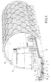
- the roadway 1 is - apart from the station areas explained in more detail below with reference to FIGS. 16 and 17 - attached within a tunnel 12 schematically illustrated in FIGS. 1 and 2 in the form of a tunnel tube, which the roadway 1 and the platform 3 at Protects transport against external influences such as snow, rain, icing or dirt.
- a route or partial route that is not to be routed underground to protect the roadway 1 by a corresponding roofing, but this is not illustrated in the drawing for the sake of simplicity.
- the carriageway or track 1 can also be modified in comparison to FIGS. 1 and 2, for example as illustrated in FIGS. 3 and 4, with the carriageway 1 in this exemplary embodiment according to FIGS. 3 and 4 having a central, extending in the direction of travel, Hump-like, in cross-section, for example, trapezoidal elevation 13, which forms the mechanical lateral guide device 11 with its two long sides for the platforms to be transported above it, for example the platform 3.
- the platform 3, seen in cross section is formed in its central region with a groove in the manner of a crank 14, so that an upwardly narrowing, downwardly open channel 15 is formed, the side walls of which Form the aforementioned mechanical cornering device 10 of the platform 3. Nevertheless, in the embodiment according to FIGS.
- FIGS. 1 and 2 there is also a generally flat design of the magnetic levitation vehicle in the form of a platform 3 on which the loads, in particular trucks 9, are transported can.
- the length of the respective platform 3 is expediently dimensioned such that a truck 9 including trailer with the usual, longest possible dimensions can be accommodated on it.
- FIGS. 3 and 4 the longitudinal edges 7 and 8 of the platform 3 and the carriageway 1 are also shown pulled up, and furthermore, part of a tunnel construction 12 is also schematically illustrated.
- Magnetic systems or linear drives such as the arrangements illustrated in FIGS. 1 and 2 at 4 and 5, have been omitted in FIGS. 3 and 4 for the purpose of simplifying and clarifying the illustration.
- the exemplary embodiments described above, according to FIGS. 1 and 2 are at least currently preferred because the mechanical lateral guide devices 10, 11 provided in the form of guide roller units 16 on the underside of the platform or a guide channel 17 in the top of the carriageway result in simpler possibilities for lateral guidance in the case of carriageway branches and junctions, as will be explained in more detail below with reference to FIGS. 9 to 17.
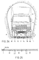
- 5 to 7 such lateral guide devices in the form of a guide roller unit 16 on the underside of a platform 3 and a guide channel 17 in the top of the road 1 are illustrated in more detail.
- 5 and 7 show the platform 3 and the guideway 1 in part and only very schematically in an end view, around the cross-sectional profile of the guide channel 17 and the design of the guide roller unit 16, which are preferably two coaxial, one above the other, rotatable about an axis 20
- Guide rollers 18, 19 includes (only one roller is shown in the schematic representation of FIG. 2) to illustrate; 5 shows the platform 3 in its (magnetically) raised transport position above the carriageway 1, whereas FIG. 7 shows the platform 3 in its rest position lowered onto the carriageway 1.
- FIG. 6 then illustrates in a partial plan view along the line AA in FIG. 5 the course of the guide channel 17 within the carriageway 1. It can also be seen that the two guide rollers 18, 19 are rotatably mounted on the common axis 20.
- the lower guide roller 19 with the smaller diameter remains at a distance from the left side wall 21 of the guide channel 17 in the drawing during the movement of the platform 3 along the carriageway 1, as can be seen from FIG. 5.
- the upper guide roller 18 is always at a lateral distance from the upper part of the right side wall 22 of the guide channel 17.
- the platform 3 - and the guide channel 17 are formed near the opposite rear transverse edge (not shown), of course need not be effective on the entire route, since on the free route usually the lateral guidance by, for example, the magnet system 5 (Fig. 1 and 2) is achieved. Rather, on the free path, the guide channel 17 - which no longer has a guide function there - is sufficiently widened so that the guide rollers 18, 19 no longer are in engagement with its side walls 21, 22 and 24, respectively.
- the mechanical lateral guiding devices 10, 11 generally function on slow-moving sections, in particular in the area of stations, above all in order to then possibly also work together with switches in the case of road branches, as will be explained in more detail below with reference to FIGS. 10 to 15.
- FIG. 8 a section of the guide channel 17 with a braking device for the guide roller units 16 is illustrated in a schematic plan view similar to that according to FIG. 6 (thus corresponding to the line A-A in FIG. 5).
- the two side walls 21, 24 of the guide channel 17 are interrupted over part of their length, i.e. lateral, recess-shaped recesses, cavities or interruptions 26, 27 (the latter below the upper part of the right side wall 22 of the guide channel 17) are provided, and in these interruptions 26, 27 there are wedge-shaped brake levers 28 which are pivotally mounted at their tip end about vertical axes , 29 provided in planes corresponding to the planes of the two guide rollers 18, 19 according to FIG.
- Fig. 8 either resiliently biased (in Fig. 8, for example, such a spring is indicated schematically at 30) or can be pivoted with the aid of an actuator (not shown), either to brake the guide rollers 18, 19 and thus the platform 3 during its movement along the guide channel 17 in accordance with the spring force acting on the brake levers 26, 27 or to cause the platform 3 to be locked.
- the upper, in the drawing, Fig. 8, left plate-shaped brake lever 28 cooperates with the upper guide roller 18 and the lower, right brake lever 29 with the lower guide roller 19.
- an actuator for the brake levers 28, 29, for example, an electrically controllable hydraulic or compressed air cylinder or an electromagnet arrangement could be used, as is conventional in itself and therefore requires no further explanation.
- the two brake levers 28, 29 can be pivoted into their associated recesses 26, 27 in such a way that they are pivoted back in the latter Position with their inner longitudinal edges facing the guide rollers 18 and 19 form an extension of the respective side wall 21 and 24 of the guide channel 17, in which case the guide roller unit 16 (and thus the associated platform 3, not shown in FIG. 8) can pass unhindered .
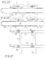
- FIG. 9 a merging of two carriageways or guide channels is illustrated in a schematic plan view similar to that in FIG. 6 or FIG. 8, the confluence of a guide channel 31 with a straight guide channel 17 being shown in detail.
- the two guide channels 17, 31 are in principle completely identical, specifically as explained above with reference to FIGS. 5 to 7, and in a manner similar to that described with reference to FIGS. 5 to 7, they act with the guide roller units 16 attached to the underside of the platform together for lateral guidance.
- the direction of movement of these guide roller units 16 is illustrated in FIG. 9 with arrows 32 and 33.
- the merging guide channel 31 can simply lead directly into the other guide channel 17. It is only important that the side wall 22 of the guide channel 17 or 31 with the gradation 23 is always on the same - e.g. right - side is present.
- the short opening area, where the respective guide roller unit 16 is not guided on both sides at the same time, does not practically impair the stability of the movement guidance of the platforms, especially if, as mentioned, there are two guide roller units 16 per platform 3.
- 10 and 11 illustrate one embodiment of a mechanical switch 35 which cooperates with the guide roller units 16 and which is shown in FIGS. 10 and 11 in its two operating positions; 10, the switch 35 guides the guide roller units 16 into a guide channel 36 branching off from the straight guide channel 17 at an acute angle, whereas the switch 35 in the operating position according to FIG. 11 guides the guide roller units 16 in the straight guide channel 17 forwards.
- FIGS. 10 and 11 corresponds again to that according to FIGS. 6, 8 or 9, i.e. a schematic plan view approximately along the line A-A in Fig. 5 (ie in a plane between the underside of the platform and the top of the roadway).
- the mechanical switch 35 consists of a plate-shaped component 37 which can be pushed back and forth in the transverse direction and is trapezoidal in plan view, in which two guide channel sections 38 and 39 are provided, the cross-sectional shape of which is identical to that of the guide channel 17 or is 36, cf.
- FIG. 5 The ability to push the plate-shaped component 37 back and forth is indicated by the double arrows 40 in FIGS. 10 and 11.
- the plate-shaped component 37 is accommodated and guided in a correspondingly trapezoidal, but wider recess 41 in the carriageway 1, and it is actuated with the aid of an actuator, which is not illustrated in detail and is conventional per se and therefore cannot be explained in more detail, e.g.
- an electromechanical drive, an electromagnetic drive or an electrically controlled hydraulic or compressed air cylinder can be pushed back and forth.
- the guide channel section 39 establishes a connection between the approaching part of the guide channel 17 and the branching guide channel 36, whereas in the position of the switch 35 according to FIG. 11 the straight guide channel section 38 in the plate-shaped component 37 provides a connection to which extends straight ahead extending guide channel 17.
- the platforms 3 while being lifted and moved forward by electromagnetic forces, can be shunted in the desired manner, especially in the area of stations, such switch systems being easier to install and control than electromagnetic switch systems, such as according to DE-B-23 22 150, DE-C-707 032 or CH-A-563 267.
- the components 42, 43 can in turn be pivoted synchronously with a conventional rotary actuator, which in turn is not illustrated in more detail, for example in the form of an electromagnetic drive or an electrically controlled compressed air or hydraulic cylinder, so that they are each jointly in one operating position, as shown in FIG 12 and 13, leading the guide roller units straight along the straight guide channel 17 and in the other operating position, according to FIGS. 14 and 15, allowing the guide roller units 16 to branch off into the guide channel 36 branching off from the straight guide channel 17.
- a conventional rotary actuator which in turn is not illustrated in more detail, for example in the form of an electromagnetic drive or an electrically controlled compressed air or hydraulic cylinder, so that they are each jointly in one operating position, as shown in FIG 12 and 13, leading the guide roller units straight along the straight guide channel 17 and in the other operating position, according to FIGS. 14 and 15, allowing the guide roller units 16 to branch off into the guide channel 36 branching off from the straight guide channel 17.
- FIGS. 13 and 15 each illustrate a schematic plan view or more precisely a sectional illustration roughly along the line BB in FIG. 5, in order in this way the cooperation of the lower guide roller 19 with that assigned to it , to better illustrate the lower pivotable switch component 43 (FIG. 15) and its retraction into the associated niche-shaped recess 44 (FIG. 13) below the upper part of the side wall 22.
- the other, upper pivotable switch component 42 is correspondingly assigned an upwardly open (optionally also covered) receiving recess 45.
- the components 42, 43 define guide channel sections in the respective operating position in order to ensure smooth, bumpless guiding of the guide roller units 16 into the respective guide channel 17 or 36.
- FIGS. 12 and 13 The direction of movement of the platforms 3 is further illustrated in FIGS. 12 and 13 with an arrow 46 and in FIGS. 14 and 15 with an arrow 47.
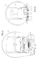
- the arrival and departure areas of stations can now be set up for the present transport system with the guide devices, mergers and branches or switches described above, in order to bring the flat platforms 3 back from the arrival area of the respective station to the departure area, one of which is described below with reference to FIG. 18 to 23 cross-slide device to be explained in more detail is provided. 16 and 17 schematically illustrate such a station with an arrival and departure area in different phases of operation in a plan view.
- FIG 16 shows more in detail, as in the arrival area 48 of FIG Station on the one hand platforms 3 with motor vehicles thereon, in particular trucks (trucks) 9, transported along a carriageway 1 in the direction according to arrow 49 and divided into, for example, 14 + 1 carriageways via switch systems, for example according to FIGS. 12 to 15 or FIGS. 10 and 11 .
- trucks trucks
- a discharge "dock" 50 there is a more or less parallel unloading of the platforms 3, ie the trucks 9 depart from the platforms 3 which have arrived there and lie directly on the carriageways.
- a separate wagon or a passenger cabin 51 is installed on one platform 3 per group of, for example, fourteen platforms 3 with trucks 9 provided to accommodate the drivers during the transport of the trucks 9 in the association.
- This wagon 51 - which arrives in the unloading dock 50 on the middle lane in order to keep the routes for the drivers from the passenger cabin or wagon 51 to the trucks 9 as short as possible - can have its own air supply and air conditioning (similar to one Plane) be present; accordingly, on the other hand, complex ventilation of the tunnel through which the - unmanned - trucks 9 are transported in the association can be dispensed with.
- FIG. 16 the situation is illustrated in the unloading dock 50 in which the first trucks 9 move away from the platforms 3 while seven trucks of the next group are already approaching, as well as the passenger cabin 51 belonging to this new group (those in the respective group or in the respective dressing is transported in the first place) is already waiting to be let into the unloading position in the unloading dock 50.
- the direction of the trucks 9 departing from the unloading dock 50 is indicated by the arrow 52 in FIG. 16.
- the departure area of the station is then indicated at 53 in FIGS. 16 and 17.
- 16 shows in the departure area 53 that phase in operation in which the trucks 9 drive onto the platforms 3 located in the loading dock 54 located next to the unloading dock 50, cf. also arrow 55.
- a second group 56 of trucks 9 is already ready for the next loading process.
- the drivers move from their trucks 9 to the passenger cabin 51 located on the central lane in the loading dock 54, which then leaves the loading dock 54 as the first in the following transport in the association and floats in the direction of departure (Arrow 57 in Fig. 16 and 17) leaves the station area. It is followed successively by the neighboring platforms 3 with the trucks parked thereon, and this phase in operation is shown in FIG. 17. From Fig. 17 it can also be seen that to accelerate the operation before the removal of the group of already loaded platforms 3, this entire group can first be transported a distance forward from the actual loading dock 54, so that the loading dock 54 for the next process as Get ready for the next loading.
- This process involves moving the now empty platforms 3 from the unloading dock 50 in the transverse direction, cf. Arrow 58 in Fig. 17 to move to the loading dock 54.
- the transversely displaced platforms 3 are provided with hatching in FIG. 17, although this is a plan view, in order to emphasize the platforms 3 so particularly. It can clearly be seen that the entire assembly of platforms 3, including the passenger cabin 51 located in the middle, is shifted in the transverse direction from the unloading dock 50 to the loading dock 54, in the situation according to FIG. 17 this transverse displacement by three lanes 1 or, accordingly, guide channels.
- the first trucks 9 and the associated passenger cabin 51 of the next group 59 which has now arrived, are already waiting in front of the actual unloading dock 50, the last three platforms 3 of which trucks 9 are just transporting the last piece.
- storage areas 60, 61 for platforms 3 and passenger cabins 51 may be present to the side of the arrival area 48 or departure area 53, so as to have a spare storage area on the one hand and, depending on the length of the storage area Routes over which the trucks 9 are to be transported, if necessary more groups or associations of fourteen plus one platform (or also, with correspondingly larger unloading and loading docks, with more platforms).
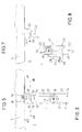
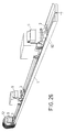
- transverse displacement device 62 for moving the platforms 3 in accordance with the transverse direction 58 (FIG. 17) from the unloading dock to the loading dock will now be explained in more detail with reference to FIGS. 18 to 23.
- this transverse displacement device 62 can extend across the entire width of the station, including the storage areas 60 and 61, in order to be able to transfer platforms from these storage areas 60, 61 to the loading dock 54 if necessary.
- the transverse displacement device 62 is designed such that it can move the platforms 3 transversely in both directions, that is to say in the direction of the arrow 58 in FIG. 17, as well as in the opposite direction. This can easily be achieved, for example, with a transverse displacement device 62 with a transport conveyor in the form of an endless conveyor 63, 64, as illustrated in FIGS. 18 to 23.
- the present transverse displacement device 62 has, in view of the fact that two guide roller units 16 are preferably provided per platform 3, in a corresponding manner also two endless conveyors 63 and 64 parallel to one another (FIGS. 19 and 20; not shown in FIG. 18).
- Each endless conveyor 63, 64 carries drivers 65 and 66, respectively, which have guide channel section-like receptacles 67 and 68 for the guide roller units 16 of the platforms 3.
- the drivers 65 of the endless conveyor 63 at the end in the loading or unloading dock (see FIG. 19 or the upper part of FIG. 18 and in a corresponding manner FIG. 22 or the upper part of FIG.
- FIGS. 18 and 21 is again a very schematic plan view similar to that according to FIG. 6 is the area of two adjacent guide channels 17 in the unloading dock 50 illustrated as an example. 18 and, accordingly, also in FIGS. 19 and 20, which show very schematic sectional representations corresponding to lines CC and DD in FIG. 18, show the phase in which the guide roller units 16 of two platforms 3 are still in alignment to the associated guide channels 17. If the endless conveyors 63, 64 are now driven in the counterclockwise direction as shown in FIGS.
- the drivers 65, 66 move on the upper run of the endless conveyors 63, 64 as shown in FIG 18 to 23 to the left, specifically in the transverse channels 72, 73 provided for this purpose in the carriageway area, which run at right angles to the guide channels 17.
- the endless conveyors 63, 64 and the associated drive devices and wheels, such as deflection or drive wheels 74, 75 are also accommodated in the bottom of these transverse channels 72, 73.
- the endless conveyors 63, 64 may, for example, be chain conveyors which are driven synchronously by the drive wheels 74, 75 designed as chain wheels, for example in that these two chain wheels are seated on a common shaft.
- 21 to 23 illustrate the situation during operation of the transverse displacement device 62, in which the drivers 65, 66 move the guide roller units 16 of the platforms 3 out of their position in alignment with the guide channels 17 (see FIGS. 18-20) and as shown in these figures - have moved to the left.
- the drivers 65, 66 are arranged on their respective endless conveyors 63 and 64 at intervals corresponding to the intervals of the guide channels 17 from one another, in order to enable the method of operation described above.
- limit switches or microswitches which are known per se, can then ensure that the endless conveyors 63, 64 come to a standstill in a position in which the drivers 65, 66 in turn are precisely aligned with their guide channel sections to the respective guide channel 17 are.
- the respective guide roller unit 16 can easily re-enter the associated guide channel 17 when the next removal of trucks is started, as explained with reference to FIGS. 16 and 17.
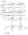
- the platform 3 as such can be made of permanent magnetic or ferromagnetic material as a whole; however, a configuration is currently preferred in which permanent magnetic reaction plates 76 and 77 are provided on the underside of the platform 3 in strip form, with associated electromagnet arrangements 78 and induction drive devices, ie linear motor devices 79 cooperate which are embedded in the top of the carriageway 1.
- the electromagnetic systems 78, 76 can be designed both for lifting the platforms 3 together with the motor vehicles located on them, such as trucks 9, and for lateral guidance during transport.
- brake pads or brake skids 80 are then shown schematically on the underside of the platform 3, with which the platforms 3 can rest on the top of the roadway, wherein they are provided with a lower friction lining, so that in the event that the power supply during of the transport is interrupted, the platforms 3 with the trucks 9 located thereon, when they land on the carriageway 1, are braked as quickly as possible to a standstill.
- the devices 78, 79 accommodated in the carriageway 1 and the guide channel 17 are effectively protected against external influences in that the tunnel construction 12 is provided for the accommodation.
- the length of these sections 81 can be adapted to the length of the platforms 3 or to the length of a floating structure of, for example, 14 + 1 platforms 3, as mentioned above, so that sections corresponding to a platform 3 or a floating structure are present and activated will.
- two adjacent sections 81 are expediently always activated, the next section 81 to which platform 3 or platform group now comes to be activated each time the rear section 81, which is broadly covered by platform 3 or the group, is switched off.
- a plurality of sections 81 or groups of sections 81 can then be spaced apart successively activated or deactivated.
- the switching sequence or activation sequence depends on the desired transport speed.
- the individual sections 81 have a length equal to a part, e.g. 1/4 of the platform length, with just as many sections 81 being activated in succession during operation that their total length corresponds to the platform length or slightly exceeds it.
- the section length is 1/4 of the platform length
- four or five sections 81 immediately following one another would thus always have to be driven at the same time, the section 81 next in the direction of travel then being activated continuously during operation, the last section 81 already run over by the platform 3 on the other hand is switched off.
- FIG. 26 part of a floating association of platforms 3 with trucks 9 located thereon is illustrated graphically, a part of the tunnel construction 12 and a roadway 1 with a guide channel 17 being shown schematically. From FIG. 26 it can also be seen how the trucks 9 can be secured on the platforms 3 with the aid of bumpers or brake blocks 82.
- tunnel tubes 12 are provided in the tunnel for the two directions of travel.
- These tunnel tubes can be adapted very closely to the maximum dimensions of trucks 9 and, as already mentioned, they do not need to be ventilated since the passenger cabin 51 has its own air supply.
- the tunnel tubes can have a diameter of 5 m. If it is now assumed that the transport speed of the platforms 3 with the trucks 9 located thereon is approximately 60 km / h, the total transport time is approximately 1.5 hours.
- the above-mentioned tunnel length of 90 km would correspond to a tunnel section for an underground tunnel from Tyrol, so that it ultimately results from the above numerical example that if the volume of transit traffic is increased by half, trucks with the present transport system will still transit in a much shorter time, namely in one and a half hours instead of four or more hours.
Abstract
Description
Die Erfindung betrifft ein Magnetschwebebahn-Transportsystem für Kraftfahrzeuge, insbesondere Lastkraftwagen, mit wenigstens einer, wenigstens eine im wesentlichen flach ausgebildete Magnetschwebe-Plattform mittels eines Magnetsystems tragenden und führenden Fahrbahn, die zumindest auf einem wesentlichen Teil ihrer Länge überdacht, z.B. in einer Tunnelröhre angeordnet ist, wobei an der Oberseite der Fahrbahn und Unterseite der Magnetschwebe-Plattform auf bestimmten Abschnitten der Fahrbahn im Normalbetrieb miteinander zusammenarbeitende Seitenführungseinrichtungen vorgesehen sind.The invention relates to a magnetic levitation transport system for motor vehicles, in particular trucks, with at least one, at least one substantially flat magnetic levitation platform by means of a magnetic system carrying and guiding roadway, which is covered at least over a substantial part of its length, e.g. is arranged in a tunnel tube, with side guidance devices which cooperate with one another in normal operation are provided on the upper side of the carriageway and the underside of the magnetic levitation platform on certain sections of the carriageway.
Es wurden bereits zahlreiche Konzepte für Magnetschwebebahnen entwickelt und getestet, wobei auch bereits die verschiedensten konstruktiven Einzelheiten, wie etwa die Realisierung der Tragkraft für das Magnetschwebefahrzeug mit Hilfe von magnetischen Anziehungs-oder aber Abstoßungskräften, Steuer- bzw. Schaltvorrichtungen für Wechselmagnete, Linearmotoren für den Vortrieb des Fahrzeuges, spezielle Magnet- bzw. Polausbildungen für das Tragen und die seitliche Führung der Magnetschwebefahrzeuge beim Fahren mit hohen Geschwindigkeiten usw. vorgeschlagen wurden. Nur beispielsweise seien aus der Vielzahl von Veröffentlichungen auf dem Gebiet der Magnetschwebebahnen die folgenden Schriften herausgegriffen: Die EP-A-144 000 offenbart eine Magnetschwebebahn, bei der magnetische Anziehungskräfte ausgenutzt werden, um das Fahrzeug zu tragen, welches seinerseits aus einem Fahrzeugkasten besteht, der über Federn mit einem eigenen Traggestell verbunden ist; die DE-B-23 22 150 und die CH-A-563 267 befassen sich insbesondere mit Fahrbahnverzweigungen bzw. Fahrbahnweichen für Magnetschwebebahnen, wobei Lösungen mit Magnetsystemen beschrieben werden; aus der US-A-4 711 182 ist ferner eine Einrichtung mit einem an einer oberen Schiene über ein Magnetsystem aufgehängten Transportbehälter bekannt, wobei die Aufhängung zusätzlich Stabilisierungsrollen zur Seitenführung enthält; diese Stabilisierungsrollen sind am mit dem Transportbehälter verbundenen Aufhängungsteil gelagert und stehen mit der Führungsschiene in Kontakt.Numerous concepts for magnetic levitation trains have already been developed and tested, with the most varied of structural details, such as the realization of the load-bearing capacity for the magnetic levitation vehicle with the aid of magnetic attraction or repulsion forces, control and switching devices for alternating magnets, linear motors for propulsion of the vehicle, special magnet or pole designs for carrying and lateral guidance of the magnetic levitation vehicles when driving at high speeds, etc. have been proposed. For example, the following documents are selected from the large number of publications in the field of magnetic levitation trains: EP-A-144 000 discloses a magnetic levitation train, in which magnetic attraction forces are used to carry the vehicle, which in turn consists of a vehicle body which is connected by springs to its own supporting frame; DE-B-23 22 150 and CH-A-563 267 deal in particular with carriageway branches or carriageway switches for magnetic levitation trains, solutions with magnet systems being described; from US-A-4 711 182 a device with a transport container suspended from an upper rail via a magnet system is also known, whereby the suspension also contains stabilizing rollers for lateral guidance; these stabilizing rollers are mounted on the suspension part connected to the transport container and are in contact with the guide rail.
Allen bekannten Magnetschwebebahn-Konzepten gemeinsam ist, daß hinsichtlich der Fahrzeugausbildung das herkömmliche Eisenbahnfahrzeug-Konzept im großen und ganzen übernommen wurde, und daß als Fahrbahnen in der Regel im Hochbau errichtete Schienensysteme dienen. Dies steht jedoch einem einfach zu bewerkstelligendem Lastentransport entgegen, und insbesondere ergeben sich Probleme, wenn Kraftfahrzeuge, inbesondere Lastkraftwagen, transportiert werden sollen, um - etwa aus Umweltschutzgründen -den Verkehr auf Straßen oder Autobahnen zu entlasten.Common to all known magnetic levitation railroad concepts is that the conventional rail vehicle concept has been largely adopted with regard to vehicle training, and that rail systems built in building construction generally serve as roadways. However, this is simply up to you counteracting load transport, and in particular problems arise when motor vehicles, especially trucks, are to be transported in order to relieve traffic on roads or highways, for example for environmental reasons.
Weiters ist bei den bekannten Magnetschwebebahnen vorgesehen, die Fahrzeuge mit Linearmotoren und Elektromagneten auszurüsten und an der Fahrbahn bzw. Fahrschiene unter Umständen nur Permanentmagnete vorzusehen. Dabei ergeben sich jedoch Probleme bei der Energieversorgung der Fahrzeuge.In the case of the known magnetic levitation trains, it is also provided that the vehicles are equipped with linear motors and electromagnets and, under certain circumstances, only permanent magnets are to be provided on the carriageway or track. However, there are problems with the energy supply to the vehicles.
Aus der Literaturstelle: Otmar Krettek, "Rollen-Schweben-Gleiten", Alba Buchverlag GmbH + CoKG, Düsseldorf, 1979, Seiten 31 und 32, sind einerseits Magnetschwebesysteme mit PKW- bzw. LKW-Beförderung und andererseits die Unterbringung der Fahrbahnen in Tunnelröhren bekannt. Eine besondere Ausbildung der Schwebefahrzeuge ist jedoch nicht geoffenbart, vielmehr wurde hier offensichtlich bloß das Prinzip der Beförderung von Kraftfahrzeugen mit der Bahn auf Magnetschwebebahnen einfach übernommen. Die GB-A-1 213 997 beschreibt ein Transportsystem, beispielsweise in Form einer "sich bewegenden" Straße, wobei aber an eine Überdachung bzw. Anbringung in einer Tunnelröhre nicht gedacht war. Dies ergibt sich beispielsweise auch aus dem Hinweis, daß diese bewegliche Straße über herkömmlichen Straßen in größeren Stadtzentren installiert werden soll. An bestimmten Zutrittsstellen sollen Förderbänder als Zubringer angebracht sein. Hieraus ergibt sich ferner unmittelbar, daß dieses bekannte Transportsystem für einen umfassenden LKW-Transit-Transport nicht geeignet wäre, wobei insbesondere auch das rasche und kontinuierliche Auffahren von Kraftfahrzeugen nicht möglich wäre, vielmehr Staus an den erwähnten Förderband-Zugangsstellen zu erwarten wären.From the literature: Otmar Krettek, "Roll-Float-Glide", Alba Buchverlag GmbH + CoKG, Düsseldorf, 1979,
In der DE-A-2 300 599 ist eine Magnetschwebebahn gezeigt, bei der eine Schwebeplattform versenkt, d.h. in einem röhrenartigen Gehäuse, angebracht ist, wobei an der Oberseite des Gehäuses eine Öffnung vorhanden ist, durch das ein biegesteifer Träger ragt, der eine Lasttragplattform mit der Magnetschwebeplattform verbindet, um so die Magneteinrichtungen besser (beispielsweise im Vergleich zur zuvor diskutierten GB-A-1 213 997) gegen Umwelteinflüsse zu schützen. Gemäß dieser Literaturstelle wird somit ein völlig anderer Weg beschritten, um Umwelteinflüsse, wie durch Schnee, Eis usw. auszuschalten, verglichen mit dem System der vorliegenden Art, wo das Magnetsystem dadurch geschützt wird, daß eine Trassenführung unter Dach bzw. in einem Tunnel vorgesehen wird. Auf diese Weise wird die Ausbildung der bekannten Magnetschwebebahn relativ kompliziert, wobei auch Schwachstellen in der Konstruktion dadurch gegeben sind, daß das biegesteife Verbindungselement notwendig ist, wobei insbesondere darauf hinzuweisen ist, daß für den Transport von LkW's eine besondere Stabilität und Festigkeit anzustreben ist.DE-A-2 300 599 shows a magnetic levitation train in which a floating platform is sunk, that is to say mounted in a tubular housing, an opening being provided on the upper side of the housing through which a rigid support projects, which carries a load-bearing platform connects to the magnetic levitation platform so as to better protect the magnetic devices (for example in comparison to the previously discussed GB-A-1 213 997) against environmental influences. According to this reference a took a different route to eliminate environmental influences such as snow, ice, etc., compared to the system of the present type, where the magnet system is protected by providing a route under the roof or in a tunnel. In this way, the design of the known magnetic levitation train is relatively complicated, with weaknesses in the construction due to the fact that the rigid connection element is necessary, and it should be pointed out in particular that particular stability and strength should be sought for the transport of trucks.
Die US-A-3 750 803 offenbart sodann ein Transportsystem, das u.a. für den Transport von Kraftfahrzeugen mit hohen Geschwindigkeiten gedacht ist, wobei auch eine Unterbringung in Tunnels erwähnt ist. Dieses bekannte Transportsystem weist Magnetschwebe-Plattformen auf, die längs einer Fahrbahn mit Elektromagneten angetrieben werden, wobei überdies eine seitliche Führung, vor allem im Bereich von Fahrbahnverzweigungen, mit Hilfe magnetischer Einrichtungen bewerkstelligt wird; zusätzlich sind, für den Notfall einer Stromunterbrechung, im Bereich der Fahrbahnverzweigungen schmale Trennwände in der Fahrbahn vorgesehen. Das bekannte Transportsystem ist ferner in der Art eines Rundkurses ausgelegt, wobei Fahrbahn-Seitenstränge mit Beschleunigungsstrecken für die Fahrzeuge bzw. Stationsbereiche an Fahrbahn-Seitensträngen vorgesehen sind, in denen die Fahrzeuge anhalten und von denen sie abfahren; diese Stationsbereiche können somit jeweils als gemeinsamer Ankunfts- und Abfahrtsbereich angesehen werden.US-A-3 750 803 then discloses a transport system which i.a. is intended for the transport of motor vehicles at high speeds, and accommodation in tunnels is also mentioned. This known transport system has magnetic levitation platforms which are driven along a carriageway with electromagnets, with lateral guidance, in particular in the region of carriageway junctions, being accomplished with the aid of magnetic devices; In addition, in the area of the carriageway branches, narrow partitions in the carriageway are provided in the event of a power cut. The known transport system is also designed in the manner of a round course, lane side strands with acceleration paths for the vehicles or station areas on lane side strands are provided, in which the vehicles stop and from which they depart; these station areas can thus be viewed as a common arrival and departure area.
Es sind noch weitere, an sich herkömmliche und wenig zielführende (zumindest was den Transport von Kraftfahrzeugen betrifft) Konzepte bekannt geworden. So kann noch darauf hingewiesen werden, daß in der DE-C-707 032 eine Schwebebahn mit einem elektromagnetischen Weichensystem geoffenbart ist. Bei der Bahn gemäß der DE-A-2 302 748 handelt es sich ferner um ein Fahrzeug mit Turbinenantrieb, bei dem zur seitlichen Führung ein Magnetsystem vorgesehen sein soll, und bei der Magnetschwebebahn gemäß der US-A-3 611 944 liegt eine Pendelaufhängung vor, wobei dementsprechend das magnetische Tragsystem zu adaptieren war, um eine Seitenneigung der Magnetschwebebahn zu ermöglichen.There are also other concepts which are conventional per se and are not very effective (at least as far as the transport of motor vehicles is concerned). It can also be pointed out that a suspension railway with an electromagnetic switch system is disclosed in DE-C-707 032. The web according to DE-A-2 302 748 is also a vehicle with turbine drive, in which a magnetic system is to be provided for lateral guidance, and in the magnetic levitation railway according to US-A-3 611 944, there is a pendulum suspension, the magnetic suspension system having to be adapted accordingly in order to enable the magnetic levitation railway to tilt to the side .
Ziel der Erfindung ist es, ein Magnetschwebebahn-Transportsystem der eingangs angegebenen Art vorzusehen, welches möglichst einfach und dabei doch betriebssicher aufgebaut ist und überdies ein bequemes Be- und Entladen erlaubt.The aim of the invention is to provide a magnetic levitation transport system of the type mentioned at the outset, which is as simple as possible and yet has a reliable construction and moreover allows convenient loading and unloading.
Das erfindungsgemäße Magnetschwebebahn-Transportsystem der eingangs angeführten Art ist dadurch gekennzeichnet, daß die Seitenführungseinrichtungen mechanische Seitenführungs-einrichtungen sind, und daß in einer Station nebeneinander ein Ankunfts- bzw. Entladebereich und ein Abfahrts- bzw. Beladebereich vorgesehen sind und den Plattformen eine Querverschubeinrichtung zu ihrer Verschiebung allgemein quer zur Fahrtrichtung zwischen dem Ankunfts- bzw. Entladebereich der Station und dem Abfahrts- bzw. Beladebereich der Station zugeordnet ist.The magnetic levitation transport system according to the invention of the type mentioned at the outset is characterized in that the lateral guiding devices are mechanical lateral guiding devices, and in that an arrival or unloading area and a departure or loading area are provided in a station next to one another and the platforms have a transverse shifting device for them Shift is generally assigned transverse to the direction of travel between the arrival or unloading area of the station and the departure or loading area of the station.
Mit einer derartigen Ausbildung wird der vorstehenden Zielsetzung in besonders vorteilhafter Weise entsprochen. Die flachen Plattformen können in den Stationen, während sie einfach auf der Fahrbahn aufliegen, problemlos beladen bzw. entladen werden, beispielsweise indem die LKW's direkt auf die Plattformen auffahren bzw. von den Plattformen abfahren. Nach dem Beladen der Plattformen werden diese magnetisch angehoben und mit der vorgesehenen Transportgeschwindigkeit - die im Fall eines LKW-Transportsystems durchaus auch bei bloß 100 km/h oder sogar bloß 60 km/h liegen kann - angetrieben. Im Hinblick darauf, daß einfache, allgemeine flache Plattformen vorgesehen sind, die als Magnetschwebefahrzeuge im Betrieb über die Fahrbahn schwebend bewegt werden sollen, ist dabei ein Freihalten der verschiedenen Bauteile des Transportsystems von Verschmutzungen und dergl. und vor allem von Schnee und Eis von besonderer Bedeutung, und dies wird dadurch sichergestellt, daß die Fahrbahn überdacht bzw. in einem Tunnel angeordnet ist. Dadurch wird überdies der Vorteil erzielt, daß das Landschaftsbild, anders als bei den herkömmlichen Hochbauten, nicht beeinträchtigt wird. Die beispielsweise bei niedrigeren Transportgeschwindigkeiten, etwa im Abfahrts- oder Ankunftsbereich von Stationen, wenn die Magnetschwebebahn-Plattformen erst beschleunigt oder aber bereits abgebremst werden, zusammenarbeitenden mechanischen Seitenführungseinrichtungen können ferner verhältnismäßig einfach ausgebildet sein, und sie ermöglichen nichtsdestoweniger eine sichere Führung der Plattformen mit den Lasten darauf zu den gewünschten Stellen.With such training, the above Objectives met in a particularly advantageous manner. The flat platforms can be easily loaded or unloaded in the stations while they are simply lying on the road, for example by the trucks driving directly onto the platforms or leaving the platforms. After loading the platforms, they are magnetically raised and driven at the intended transport speed - which in the case of a truck transport system can be as low as 100 km / h or even as low as 60 km / h. In view of the fact that simple, general flat platforms are provided which are to be moved as magnetic levitation vehicles in operation over the road, keeping the various components of the transport system free from dirt and the like and especially from snow and ice is of particular importance , and this is ensured by the fact that the roadway is covered or arranged in a tunnel. This also has the advantage that the landscape, unlike conventional buildings, is not affected. The mechanical lateral guiding devices that work together, for example at lower transport speeds, for example in the departure or arrival area of stations, when the magnetic levitation platforms are only accelerating or already decelerating, can also be relatively simple, and they nonetheless enable the platforms to be safely guided with the loads then to the desired places.
Beim vorliegenden Transportsystem werden die Plattformen zweckmäßigerweise in einer Fahrtrichtung jeweils in Reihe hintereinander befördert, wobei jedoch ein Auffächern der Fahrbahnen in den beiden Fahrtrichtungen im jeweiligen Stationsbereich, etwa zur Erleichterung der Ladetätigkeit bzw. aus Platzgründen, vorteilhaft sein wird. Um vor allem in einem solchen Fall die Plattformen, die laufend ankommen, wieder für eine Abfahrt in der Station bereitzustellen, oder ganz allgemein im Fall von zwei oder mehr Fahrbahnen in einer Station können schließlich mit der angegebenen Querverschubeinrichtung die Plattformen automatisch zwischen den Bereichen der Station bewegt werden, ohne daß etwa ein zusätzliches Manipulieren, wie Aufladen auf ein Transportfahrzeug, oder ein umständliches Rangieren, wie bei Eisenbahn-Bahnhöfen, notwendig wäre. Eine solche - mechanisch arbeitende - Querverschubeinrichtung ist im vorliegenden Fall auch deshalb problemlos möglich, weil die vorgesehenen Magnetschwebe-Plattformen im unbeladenen Zustand, anders als herkömmliche Eisenbahnwaggons, eine relativ geringe Masse haben können.In the present transport system, the platforms are expediently conveyed in a row in a direction of travel, but fanning out the lanes in the two directions of travel in the respective station area will be advantageous, for example to facilitate loading or for reasons of space. In order to make the platforms that are constantly arriving ready for departure in the station, especially in such a case, or more generally in the case of two or more lanes in a station, the platforms can be moved automatically between the areas of the station with the specified cross-shifting device can be moved without an additional manipulation, such as loading onto a transport vehicle, or a cumbersome maneuvering, such as at railway stations, would be necessary. Such a - mechanically working - cross slide device is also possible in the present case without any problems because the magnetic levitation platforms provided, unlike conventional railway wagons, can have a relatively low mass when unloaded.
Um beim Be- bzw. Entladen ein stabiles Aufliegen der Plattformen auf der Fahrbahn zu ermöglichen, damit beispielsweise LKW's problemlos auf die Plattformen auffahren bzw. von ihnen abfahren können, ist es von besonderem Vorteil, wenn die Fahrbahn eine im allgemeinen ebene Oberseite und die oberhalb davon geführte Plattform eine im allgemeinen ebene Unterseite aufweist. An sich wäre es aber auch grundsätzlich denkbar, beispielsweise im Profil in der Art einer Kröpfung ausgebildete Plattformen und entsprechend geformte Fahrbahnen vorzusehen, wobei dadurch nicht nur ein Versteifungseffekt, sondern zugleich auch ein Seitenführungseffekt bei der Bewegung der Plattformen entlang der Fahrbahnen erzielt werden kann.In order to enable the platforms to rest on the roadway during loading and unloading, so that, for example, trucks can easily drive onto and off the platforms, it is particularly advantageous if the roadway has a generally flat top and the top of which platform has a generally flat underside. In itself, however, it would also be conceivable in principle, for example, to provide platforms designed in the manner of an offset and correspondingly shaped carriageways, whereby not only a stiffening effect but also a lateral guiding effect when moving the platforms along the carriageways can thereby be achieved.
Es ist auch empfehlenswert, die Längsränder der Plattformen hochzuziehen und die Fahrbahnen mit entsprechenden hochgezogenen Führungs-Längsrändern vorzusehen, wobei in diesen Längsränderbereichen auch ein magnetisches bzw. elektromagnetisches Führungssystem, wie an sich bekannt, angeordnet werden kann.It is also advisable to pull up the longitudinal edges of the platforms and to provide the roadways with corresponding raised longitudinal guide edges, a magnetic or electromagnetic guide system, as known per se, can also be arranged in these longitudinal edge regions.
Für eine sichere, reibungsarme Seitenführung mit Hilfe der mechanischen Seitenführungseinrichtungen ist es von besonderem Vorteil, wenn in der Fahrbahn-Oberseite ein Führungskanal eingelassen ist und an der Plattform-Unterseite wenigstens eine Führungsrolleneinheit mit wenigstens einer um eine vertikale Achse drehbaren, in den Führungskanal eingreifenden Führungsrolle angebracht ist. Vor allem ist es hier weiters vorteilhaft, wenn in der bzw. jeder Führungsrolleneinheit zwei Führungsrollen übereinander vorgesehen sind, von denen jeweils eine an einer der beiden Längsseitenwände des Führungskanals geführt ist.For safe, low-friction lateral guidance with the aid of the mechanical lateral guide devices, it is particularly advantageous if a guide channel is embedded in the top of the carriageway and at least one guide roller unit with at least one guide roller which rotates about a vertical axis and engages in the guide channel on the platform underside is appropriate. Above all, it is further advantageous here if two or more guide rollers are provided one above the other in the or each guide roller unit, one of which is guided on one of the two longitudinal side walls of the guide channel.
Dabei könnten an sich die Führungsrollen um verschiedene vertikale Achsen drehbar sein; um hier jedoch den konstruktiven Aufwand besonders gering zu halten, hat es sich als günstig erwiesen, wenn die beiden Führungsrollen koaxial angeordnet sind und verschieden große Durchmesser haben, und zumindest eine Längsseitenwand des Führungskanals abgestuft ausgebildet ist, wobei die eine, durchmesserkleinere Führungsrolle im durch die Stufe bewirkten engeren Teil des Führungskanals an dessen abgestufter Längsseitenwand und die andere, durchmessergrößere Führungsrolle an der gegenüberliegenden Längsseitenwand des Führungskanals anliegt.The guide rollers themselves could be rotatable about different vertical axes; However, in order to keep the design effort particularly low here, it has proven to be cheap proven, if the two guide rollers are arranged coaxially and have different diameters, and at least one longitudinal side wall of the guide channel is designed in a stepped manner, the one, smaller-diameter guide roller in the narrower part of the guide channel caused by the step on its stepped longitudinal side wall and the other, larger-diameter guide roller bears on the opposite longitudinal side wall of the guide channel.
Ein Vorteil liegt bei derartigen mechanischen Seitenführungseinrichtungen auch darin, daß bei Fahrbahn-Zusammenführungen und -verzweigungen verhältnismäßig einfache Leit- bzw. Lenkeinrichtungen für die Plattformen möglich sind, die nichtsdestoweniger ein zuverlässiges Rangieren der Plattformen erlauben. So ist es inbesondere vorteilhaft, daß bei Fahrbahnzusammenführungen einer der Führungskanäle einfach direkt in den anderen einmünden kann. Bei Fahrbahn-Verzweigungen können andererseits mechanische Weichen mit seitlichen bewegbaren Führungskanal-Seitenwandteilen vorgesehen sein. Diese mechanischen Weichen können ähnlich wie herkömmliche Weichen arbeiten und betätigt werden, etwa über an sich herkömmliche elektrische bzw. elektromagnetische oder elektromechanische oder aber elektrohydraulische oder elektropneumatische Stellantriebe.An advantage of such mechanical lateral guiding devices is also that relatively simple guidance or steering devices for the platforms are possible in the case of roadway mergers and branches, which nevertheless allow reliable maneuvering of the platforms. It is particularly advantageous that one of the guide channels can easily open directly into the other when the road is merged. In the case of road branchings, on the other hand, mechanical switches can be provided with laterally movable guide channel side wall parts. These mechanical switches can work and be operated in a similar manner to conventional switches, for example via conventional electrical or electromagnetic or electromechanical or else electrohydraulic or electropneumatic actuators.
Beispielsweise ist hier eine besonders vorteilhafte Ausführungsform dadurch gekennzeichnet, daß in der Fahrbahn im Bereich der Verzweigung zumindest ein schwenkbarer Bauteil mit einem oder mehreren Führungskanal-Seitenwandteilen untergebracht ist, der bzw. die in jeder von zwei Schwenklagen eine Verbindung zu einem von zwei nachfolgenden, auseinanderführenden Führungskanälen bildet bzw. bilden. Andererseits ist es aber auch möglich, daß in der Fahrbahn im Bereich der Verzweigung ein in Querrichtung zwischen zwei Betriebsstellungen verschiebbarer Plattenbauteil mit zwei nebeneinander vorgesehenen Führungskanal-Abschnitten untergebracht ist, von denen der eine in der einen Betriebsstellung mit dem einen nachfolgenden Führungskanal und der andere in der anderen Betriebsstellung mit dem anderen nachfolgenden Führungskanal eine Verbindung herstellt.For example, a particularly advantageous embodiment is characterized in that at least one pivotable component with one or more guide channel side wall parts is accommodated in the area of the branching in the carriageway, which, in each of two pivot positions, connects to one of two subsequent, diverging ones Forms or form guide channels. On the other hand, it is also possible that in the roadway in the area of the branching a slidable component in the transverse direction between two operating positions is accommodated with two side-by-side guide channel sections, one of which is in one operating position with the one subsequent guide channel and the other in connects the other operating position with the other subsequent guide channel.
Um die Plattformen im Stationsbereich zuverlässig abbremsen bzw. feststellen zu können, ist es weiters auch von Vorteil, wenn in einer z.B. nischenförmigen Unterbrechung zumindest einer der Längsseitenwände des Führungskanals ein aus einer Ruhelage, in der er seitlich zur Längsseitenwand ausgerichtet ist, in den Führungskanal hinein bewegbarer, z.B. schwenkbarer, Bremshebel angeordnet ist.To reliably brake the platforms in the station area or to be able to determine, it is also advantageous if, for example in a niche-shaped interruption, at least one of the longitudinal side walls of the guide channel has a brake lever which can be moved into the guide channel, for example pivotable, from a rest position in which it is aligned laterally to the longitudinal side wall is.
Für eine einfache Ausbildung der Querverschubeinrichtung kann vorgesehen werden, daß diese zumindest einen sich quer zu den Fahrbahnen erstreckenden Transportförderer mit wenigstens einem Mitnehmer für die Plattformen aufweist.For a simple design of the transverse displacement device, it can be provided that it has at least one transport conveyor extending transversely to the carriageways with at least one driver for the platforms.
Dabei ergibt sich im Zusammenhang mit den weiter oben erwähnten mechanischen Seitenführungseinrichtungen auch eine konstruktiv vorteilhafte Möglichkeit dadurch, daß der mit den an der Plattform-Unterseite vorgesehenen Seitenführungseinrichtungen, gegebenenfalls Führungsrolleneinheiten, zusammenarbeitende Mitnehmer in wenigstens einem Querkanal aufgenommen und geführt ist. In diesem Querkanal werden dann die Plattform-Seitenführungseinrichtungen bei der Querverschiebung der Plattformen mittelbar, über die mit ihrem zusammenarbeitenden Mitnehmer, geführt.In connection with the mechanical lateral guide devices mentioned above, there is also a structurally advantageous possibility in that the driver cooperating with the lateral guide devices provided on the underside of the platform, possibly guide roller units, is received and guided in at least one transverse channel. In this transverse channel, the platform lateral guiding devices are then guided indirectly when the platforms are shifted, via the drivers that work with them.
Von besonderem Vorteil ist es hiebei weiters, wenn der in der Ruhestellung in Ausrichtung zu einem der Führungskanäle im Ankunftsbereich der Station ausgerichtete Mitnehmer eine Aufnahme in Form eines Führungskanalabschnittes für die Führungsrolleneinheiten aufweist. In der Ruhestellung bilden somit die Mitnehmer mit ihrer Aufnahme einen Teil des jeweiligen Führungskanals, d.h. die Wände der Aufnahme sind zu den Seitenwänden des übrigen Führungskanals ausgerichtet, und wenn sich die jeweilige Führungsrolleneinheit innerhalb dieser Mitnehmer-Aufnahme befindet, kann ein Querverschub, falls gewünscht, durchgeführt werden.It is also particularly advantageous if the driver oriented in the rest position in alignment with one of the guide channels in the arrival area of the station has a receptacle in the form of a guide channel section for the guide roller units. In the rest position, the drivers with their receptacles thus form part of the respective guide channel, i.e. the walls of the receptacle are aligned with the side walls of the rest of the guide channel, and if the respective guide roller unit is located within this driver receptacle, a transverse displacement can be carried out, if desired.
Zum Querverschieben kann an sich ein hin- und hergehend arbeitender Transportförderer vorgesehen werden, was sich jedoch im Hinblick auf die zumeist erforderliche große Hublänge als nicht besonders vorteilhaft erweisen kann. Demgemäß ist es günstiger, wenn, wie dies in Weiterbildung der Erfindung vorgesehen ist, der Transportförderer durch einen Endlosförderer, z.B. eine Endloskette, gebildet ist.A reciprocating transport conveyor can be provided for transverse displacement, but this cannot prove to be particularly advantageous in view of the large stroke length that is usually required. Accordingly, it is more advantageous if, as is provided in a development of the invention, the transport conveyor is formed by an endless conveyor, for example an endless chain.
Eine besonders vorteilhafte Ausführungsform des erfindungsgemäßen Transportsystems ist sodann dadurch gekennzeichnet, daß im Ankunftsbereich sowie im Abfahrtsbereich der Station jeweils mehrere, in ihrer jeweiligen Anzahl gleich viele Fahrbahnen nebeneinander vorgesehen sind, um eine parallele Be-bzw. Entladung der Plattformen zu ermöglichen, und am Transportförderer zumindest gleich viele Mitnehmer vorgesehen ist, deren Abstände voneinander den Abständen der Fahrbahnen, gegebenenfalls der Seitenführungseinrichtungen bzw. Führungskanäle, entsprechen.A particularly advantageous embodiment of the transport system according to the invention is then characterized in that in the arrival area and in the departure area of the station several lanes, each of the same number in their respective number, are provided next to one another in order to ensure parallel loading or unloading. To enable unloading of the platforms, and at least the same number of drivers is provided on the transport conveyor, the distances between which correspond to the distances of the carriageways, possibly the lateral guiding devices or guide channels.
Für eine stabile Seitenführung der Plattformen ist es auch vorteilhaft, wenn die bzw. jede Plattform an ihrer Unterseite zwei in Fahrtrichtung hintereinander angeordnete Führungsrolleneinheiten aufweist. Dabei kann dann weiters die Querverschubeinrichtung zwei zueinander parallele Quer-Transportförderer aufweisen, deren Abstand voneinander dem Abstand der Führungsrolleneinheiten entspricht.For stable lateral guidance of the platforms, it is also advantageous if the or each platform has two guide roller units arranged one behind the other in the direction of travel. The transverse displacement device can then furthermore have two transverse transport conveyors which are parallel to one another and whose distance from one another corresponds to the distance between the guide roller units.
Was das Magnetsystem bzw. die Elektromagnetanordnung zum Tragen und Führen sowie den Linearantrieb zum Vortrieb der Magnetschwebe-Plattformen beim vorliegenden Transportsystem betrifft, so können hier an sich grundsätzlich bekannte Systeme und Anordnungen verwendet werden, insbesondere solche, bei denen magnetische Abstoßungskräfte zum Tragen der Magnetschwebefahrzeuge ausgenutzt werden. Derartige Systeme bedürfen hinsichtlich ihres Aufbaues, da sie hinlänglich bekannt und in der Literatur beschrieben sind (außer den bereits einleitend genannten Dokumenten können auch noch beispielsweise die DE-C-36 35 258, die DE-C-28 13 023, die DE-C-31 14 462, die DE-A-35 23 345 oder die CH-A-598 040 erwähnt werden) keiner weiteren Erläuterung. Es ist hier aber anzuführen, daß beim erfindungsgemäßen Transportsystem, vor allem wenn es zum Transport von LKW's und dergl. mit verhältnismäßig niedrigen Transportgeschwindigkeiten vorgesehen ist, in der Regel keine besonderen Anforderungen an das elektromagnetische Trag- und Führungssystem sowie an den Linearantrieb zu stellen sind, so daß zumeist bereits verhältnismäßig einfache, wenig aufwendige Magnetanordnungen und Steuerungen ausreichen werden.With regard to the magnet system or the electromagnet arrangement for carrying and guiding as well as the linear drive for propelling the magnetic levitation platforms in the present transport system, basically known systems and arrangements can be used here, in particular those in which magnetic repulsive forces are used to carry the magnetic levitation vehicles will. Such systems require in terms of their structure, since they are well known and described in the literature (in addition to the documents already mentioned in the introduction, DE-C-36 35 258, DE-C-28 13 023, DE-C -31 14 462, DE-A-35 23 345 or CH-A-598 040) no further explanation. However, it should be mentioned here that in the transport system according to the invention, especially if it is intended for the transport of trucks and the like at relatively low transport speeds, there are generally no special requirements for the electromagnetic carrying and guiding system and for the linear drive, so that usually relatively simple, less complex magnet arrangements and controls will suffice.
Im Hinblick darauf, daß beim vorliegenden Transportsystem jedoch flache Schwebeplattformen als Magnetschwebe-Fahrzeuge vorgesehen sind, so daß sich Elektromagnetsysteme, Linearmotoren und zugehörige Energieversorgungseinrichtungen kaum unterbringen lassen, ist es in Abgehen vom herkömmlichen Konzept, bei dem wie erwähnt die Fahrzeuge mit diesen Einrichtungen ausgerüstet sind, erfindungsgemäß weiters von Vorteil, wenn die Plattform zumindest teilweise aus Permanentmagnetmaterial ausgebildet ist bzw. mit Permanentmagneten ausgerüstet ist, die zum Heben und Führen der Plattform mit in der Fahrbahn vorgesehenen Elektromagneten zusammenarbeiten, wobei die Fahrbahn überdies mit einem Linearmotor für die Plattform ausgerüstet ist. Auf diese Weise wird die Ausbildung der Plattform bzw. Plattformen einfach gehalten, und die mit elektrischer Energie zu versorgenden Einrichtungen werden in der stationären Fahrbahn untergebracht.In view of the fact that in the present transport system, however, flat floating platforms are used as magnetic levitation vehicles are provided so that electromagnet systems, linear motors and associated energy supply devices can hardly be accommodated, it is further advantageous according to the invention in departure from the conventional concept, in which, as mentioned, the vehicles are equipped with these devices, if the platform is at least partially made of permanent magnet material or is equipped with permanent magnets which cooperate with the electromagnets provided in the carriageway for lifting and guiding the platform, the carriageway also being equipped with a linear motor for the platform. In this way, the design of the platform or platforms is kept simple, and the devices to be supplied with electrical energy are accommodated in the stationary carriageway.
Um dabei im Fall von längeren Strecken bzw. Fahrbahnen die elektrisch zu aktivierenden Einrichtungen, nämlich Linearmotor und Elektromagnete, nicht dauernd über die gesamte Fahrbahnlänge anschalten zu müssen, wobei Energie vergeudet würde, ist es hier weiters günstig, wenn die Elektromagnete und/oder der Linearmotor in Längs-oder Fahrtrichtung in getrennte, gesondert ansteuerbare Abschnitte unterteilt sind, die aufeinanderfolgend erregbar bzw. aktivierbar sind. Die genannten Abschnitte werden dabei, etwa über eine Computersteuerung, im Takt aufeinanderfolgend, entsprechend der gewünschten Transportgeschwindigkeit für die Plattform bzw. Plattformen, angeschaltet, d.h. aktiviert. Dabei können relativ kurze Abschnitte vorgesehen sein, die jeweils gruppenweise, unter gegenseitiger Überlappung der Gruppen, aktiviert werden, um den Energieaufwand niedrig zu halten. Andererseits ist es, um die Ansteuerung für die Aktivierung der Abschnitte nacheinander möglichst einfach zu halten, manchmal auch vorteilhaft, wenn die Abschnitte in ihrer Länge ungefähr der Länge der Plattformen entsprechen.In order not to have to continuously switch on the electrically activated devices, namely the linear motor and electromagnets over the entire length of the road in the case of longer distances or roadways, with energy being wasted, it is furthermore favorable here if the electromagnets and / or the linear motor are divided in the longitudinal or direction of travel into separate, separately controllable sections which can be excited or activated in succession. The sections mentioned are switched on, for example via a computer control, in succession in accordance with the desired transport speed for the platform or platforms, i.e. activated. In this case, relatively short sections can be provided, which are activated in groups, with mutual overlap of the groups, in order to keep the energy expenditure low. On the other hand, in order to keep the activation for the activation of the sections in succession as simple as possible, it is sometimes also advantageous if the length of the sections corresponds approximately to the length of the platforms.
In diesem Fall können beispielsweise zum Transport der bzw. jeder Plattform jeweils zwei benachbarte Abschnitte aktiviert werden.In this case, two adjacent sections can be activated, for example, to transport the or each platform.
Wie bereits vorstehend erwähnt eignet sich das vorliegende Transportsystem besonders zum Transport von mehreren Plattformen in Gruppen, in einem Schwebeverband, wobei die Plattformen innerhalb der Gruppe relativ geringe Abstände voneinander einhalten können. In diesem Zusammenhang kann es auch günstig sein, wenn die Abschnitte in ihrer Länge einer Gruppe von in einem Schwebeverband hintereinander zu transportierenden Plattformen entsprechen.As already mentioned above, the present transport system is particularly suitable for the transport of several platforms in groups, in a floating association, the platforms can maintain relatively small distances within the group. In this context, it can also be advantageous if the length of the sections corresponds to a group of platforms to be transported one behind the other in a floating structure.
Um aus Energiegründen jeweils gerade nur die unbedingt notwendigen Abschnitte anschalten zu können, ist es dagegen auch vorteilhaft, wenn die Abschnitte in ihrer Länge einem Teil der Länge der Plattformen entsprechen und jeweils gleichzeitig mehrere Abschnitte hintereinander, in zumindest ungefährer Entsprechung zur Länge der Plattformen aktivierbar sind.On the other hand, in order to be able to switch on only the absolutely necessary sections for energy reasons, it is also advantageous if the sections correspond in length to part of the length of the platforms and a plurality of sections can be activated at the same time, at least approximately in correspondence with the length of the platforms .
Um bei einem Ausfall des elektrischen Systems die Plattform oder Plattformen rasch abbremsen und so, bei einem Transport in der Gruppe, ein gegenseitiges Auffahren oder Aneinanderstoßen zu verhindern, ist es schließlich auch von Vorteil, wenn die Plattform an ihrer Unterseite mit Bremskufen oder kufen- bzw. streifenartigen Bremsbelägen versehen ist. Dabei können die Bremskufen, mit denen die jeweilige Plattform beim Ausfall des elektrischen Systems und damit der elektromagnetischen Tragkraft auf die Fahrbahn aufsetzen, auch gefedert an der Plattformunterseite angebracht sein.Finally, in order to brake the platform or platforms quickly in the event of a failure of the electrical system and thus prevent mutual collision or collision when being transported in a group, it is also advantageous if the underside of the platform is equipped with brake runners or skids is provided strip-like brake pads. The brake runners with which the respective platform touches the road in the event of failure of the electrical system and thus the electromagnetic load-bearing capacity can also be spring-mounted on the underside of the platform.
Zusammenfassend kann zum erfindungsgemäßen Magnetschwebebahn-Transportsystem ausgeführt werden, daß der Einsatz von Magnetschwebe-Plattformen mit mechanischen Seitenführungseinrichtungen sowie das Vorsehen einer Querverschubeinrichtung für die Plattformen in den Stationen zwischen dem Ankunfts- und dem Abfahrbereich eine Kontinuität von LKW-Transporten ermöglicht, wobei der von den bisherigen Anschauungen in Zusammenhang mit Magnetschwebebahnen völlig divergierende Gedanke zugrundeliegt, eine höhere Anzahl von LKW-Transporten pro Zeiteinheit anstatt durch Erhöhung der Geschwindigkeit der Transportfahrzeuge durch eine Kontinuität im Transport, d.h. durch eine Vielzahl von sich hintereinander bewegenden Magnetschwebe-Plattformen (die durchaus auch mit relativ langsamer Geschwindigkeit angetrieben werden können) vorzusehen. Für die gewünschte Kontinuität ist die angegebene Querverschubeinrichtung insofern von Bedeutung, da so im Ankunfts- bzw. Abfahrtsbereich ein Abfahren bzw. Auffahren von Kraftfahrzeugen von den bzw. auf die Plattformen in Fahrtrichtung problemlos ermöglicht wird, im Gegensatz etwa zu einer Anordnung, wo eine Fahrbahn-Verbindungsstrecke zwischen Ankunftsbereich und Abfahrbereich vorgesehen ist, um die Plattform schwebend vom, Ankunftsbereich zum Abfahrbereich zu überführen: Hier müßten die Kraftfahrzeuge mehr oder weniger von der Seite her auf die Plattformen auffahren bzw. seitlich von ihnen abfahren, was mit einem höheren Zeitaufwand verbunden wäre. Durch die erfindungsgemäße Konzeption können somit Wartezeiten in den Stationen praktisch ausgeschaltet werden, d.h. durch die gegebene Kontinuität im Transport und die hiefür mitverantwortliche Querverschubeinrichtung für die Plattformen können die Kraftfahrzeuge laufend auf die in den Abfahrbereich überstellten Plattformen auffahren und sodann praktisch unmittelbar mit Hilfe dieser Plattformen abtransportiert werden bzw. im Ankunftsbereich von den laufend ankommenden Plattformen problemlos abfahren.In summary, the magnetic levitation transport system according to the invention can be carried out in such a way that the use of magnetic levitation platforms with mechanical lateral guiding devices and the provision of a transverse displacement device for the platforms in the stations between the arrival and departure areas enable a continuity of truck transports, of which the previous views in connection with magnetic levitation trains are based on completely divergent ideas, a higher number of truck transports per unit of time instead of increasing the speed of the transport vehicles due to a continuity in transport, i.e. through a large number of successively moving magnetic levitation platforms (which can also be relative) can be driven at a slower speed). The specified transverse displacement device is important for the desired continuity, since in the arrival or departure area, a departure or ascent of Motor vehicles from or onto the platforms in the direction of travel are made possible without any problems, in contrast, for example, to an arrangement where a carriageway connecting section between the arrival area and the departure area is provided in order to transfer the platform in a floating manner from the arrival area to the departure area: here the motor vehicles would have to do more or less drive onto the platforms from the side or move laterally from them, which would take more time. With the design according to the invention, waiting times in the stations can thus be practically eliminated, that is, given the continuity in the transport and the cross-shifting device for the platforms which is responsible for this, the motor vehicles can continuously drive onto the platforms transferred into the departure area and then be transported practically directly using these platforms be able to leave the incoming platforms without any problems in the arrival area.
Die Erfindung wird nachstehend anhand von in der Zeichnung dargestellten, besonders bevorzugten Ausführungsbeispielen noch weiter erläutert. Es zeigen:
- Fig. 1 eine schaubildiche Ansicht eines Teiles einer Tunnelkonstruktion mit einer Fahrbahn und einer darüber vorgesehenen Plattform, auf der ein LKW transportiert wird;
- Fig. 2 eine schematische Ansicht dieses Transportsystems gemäß Fig. 1;
- Fig. 3 eine schaubildliche Ansicht ähnlich Fig. 1 eines demgegenüber etwas modifizierten Transportsystems;
- Fig. 4 eine zum Transportsystem gemäß Fig. 3 gehörige schematische Ansicht ähnlich Fig. 2;
- Fig. 5 eine schematische Teil-Stirnansicht einer etwa bei einem Transportsystem gemäß Fig. 1 und 2 vorgesehenen mechanischen Seitenführungseinrichtung mit zwei in einem Führungskanal aufgenommenen Führungsrollen;
- Fig. 6 eine schematische Draufsicht bzw. Schnittdarstellung etwa gemäß der Linie A-A in Fig. 5;
- Fig. 7 eine der Stirnansicht gemäß Fig. 5 ähnliche Stirnansicht, wobei nun jedoch die teilweise weggebrochen gezeigte Plattform in ihrem abgesenkten Ruhezustand veranschaulicht ist;
- Fig. 8 in einer schematischen Draufsicht bzw. Schnittdarstellung, entsprechend der Darstellungsart in Fig. 6, einen Teil eines Führungskanals mit darin aufgenommener Führungsrolleneinheit sowie mit einer Bremseinrichtung;
- Fig. 9 eine entsprechende schematische Darstellung einer Zusammenführung von zwei in einem spitzen Winkel ineinander mündenden Fahrbahnen bzw. Führungskanälen;
- die Fig. 10 und 11 in ebenfalls den Darstellungen gemäß Fig. 6, 8
oder 9 entsprechenden Draufsichten eine Verzweigung mit einer mechanischen Weiche, jeweils in einer ihrer beiden Betriebsstellungen; - die Fig. 12
und 13 bzw. 14 und 15 eine andere Ausführungsform einer Verzweigung mit Weiche, wobei die Fig. 12 und 14 in einer Draufsicht bzw. Schnittdarstellung ähnlich etwa Fig. 8, Fig. 10 bzw. 11, im allgemeinen gemäß der Linie A-A in Fig. 5, die zwei Betriebsstellungen der Weiche zeigen und die Fig. 13 und 15 zugehörige schematische Schnittdarstellungen dieser beiden Betriebsstellungen im wesentlichen gemäß der Linie B-B in Fig. 5 sind; - Fig. 16 eine schematische Draufsicht auf eine Station mit einem Ankunftsbereich und einem Abfahrtsbereich, mit jeweils mehreren aufgefächerten Fahrbahnen, wobei der Zustand des Be- und Entladens der Plattformen veranschaulicht ist;
- Fig. 17 eine der Fig. 16 entsprechende schematische Draufsicht auf eine Station mit Ankunfts- und Abfahrtbereich, nunmehr jedoch in der Phase, in der der Be- bzw. Entladevorgang beendet ist und eine Gruppe von Plattformen vom Ankunftsbereich zum Abfahrtsbereich quer verschoben wird;
- Fig. 18 in einer schematischen Teil-Draufsicht einen Teil einer Querverschubeinrichtung für die Plattformen;
- die Fig. 19 und 20 schematische Teil-Schnittdarstellungen dieser Querverschubeinrichtung gemäß Fig. 18, im wesentlichen gemäß den Linien C-C bzw. D-D in Fig. 18;
- die Fig. 21
bis 23 in den Fig. 18, 19und 20 entsprechenden Grundriß-bzw. Querschnittsdarstellungen diese Querverschubeinrichtung in einer Phase nach ihrer Ingangsetzung aus der in den Fig. 18bis 20 veranschaulichten Ruhestellung; - Fig. 24 eine schematische Stirnansicht eines weiteren Transportsystems, bei dem alle elektromagnetischen Einrichtungen einschließlich des Linearmotors stationär in der Fahrbahn untergebracht sind;
- Fig. 25 eine ganz schematische Teil-Längsschnittdarstellung bzw. Seitenansicht der Fahrbahn dieses Transportsystems gemäß Fig. 24, zur Veranschaulichung der Unterteilung der elektromagnetischen Einrichtungen in voneinander getrennte Abschnitte;
- und Fig. 26 schaubildlich einen Teil eines Schwebeverbandes einer Gruppe von Plattformen mit LKW's beim Transport.
- Figure 1 is a diagrammatic view of part of a tunnel construction with a roadway and a platform provided thereon, on which a truck is transported;
- FIG. 2 shows a schematic view of this transport system according to FIG. 1;
- 3 shows a diagrammatic view similar to FIG. 1 of a somewhat modified transport system;
- FIG. 4 shows a schematic view similar to FIG. 2 belonging to the transport system according to FIG. 3;
- 5 shows a schematic partial end view of a mechanical lateral guide device provided, for example, in a transport system according to FIGS. 1 and 2 with two guide rollers accommodated in a guide channel;
- FIG. 6 shows a schematic top view or sectional illustration approximately along line AA in FIG. 5;
- FIG. 7 is a front view similar to the front view according to FIG. 5, but now the platform shown partially broken away is illustrated in its lowered idle state;
- 8 is a schematic top view or sectional view, corresponding to the type of illustration in FIG. 6, of part of a guide channel with a guide roller unit accommodated therein and with a braking device;
- 9 shows a corresponding schematic illustration of a merging of two carriageways or guide channels that open into one another at an acute angle;
- 10 and 11 in the top views corresponding to the representations according to FIGS. 6, 8 or 9, a branching with a mechanical switch, in each case in one of its two operating positions;
- 12 and 13 or 14 and 15 show another embodiment of a branching with a switch, FIGS. 12 and 14 in a plan view or sectional view similar to FIG. 8, 10 or 11, generally along the line AA in FIG. 5, which show two operating positions of the switch and FIGS. 13 and 15 are associated schematic sectional representations of these two operating positions substantially along the line BB in FIG. 5;
- 16 shows a schematic plan view of a station with an arrival area and a departure area, each with a plurality of fanned-out lanes, the state of the loading and unloading of the platforms being illustrated;
- 17 shows a schematic plan view corresponding to FIG. 16 of a station with an arrival and departure area, but now in the phase in which the loading or unloading process has ended and a group of platforms is moved transversely from the arrival area to the departure area;
- 18 shows a schematic partial top view of part of a transverse displacement device for the platforms;
- FIGS. 19 and 20 are schematic partial sectional views of this transverse displacement device according to FIG. 18, essentially along lines CC and DD in FIG. 18;
- 21 to 23 in FIGS. 18, 19 and 20 corresponding floor plan or. Cross-sectional representations of this transverse displacement device in a phase after it has been started from the rest position illustrated in FIGS. 18 to 20;
- Fig. 24 is a schematic end view of another Transport system in which all electromagnetic devices including the linear motor are stationary in the lane;
- FIG. 25 is a very schematic partial longitudinal sectional view or side view of the roadway of this transport system according to FIG. 24, to illustrate the subdivision of the electromagnetic devices into separate sections;
- and FIG. 26 shows a part of a suspension system of a group of platforms with trucks during transport.
In Fig. 1 und 2 ist schematisch eine Ausführungsform eines Magnetschwebebahn-Transportsystems veranschaulicht, die derzeit als beste Ausführungsform betrachtet wird, und bei der oberhalb bzw. innerhalb einer flachen, wannenförmigen, einen breiten, ebenen Boden 2 aufweisenden Fahrbahn oder Fahrschiene 1 Magnetschwebe-Plattformen, wie die Plattform 3, durch magnetische Kräfte getragen und vorwärts bewegt werden. In Fig. 1 und 2 sind nur ganz schematisch Magnetsysteme 4, 5 zum Tragen, Antreiben und Führen der Plattformen 3 längs der Fahrbahn 1 veranschaulicht. Diese Magnetsysteme 4, 5 können in an sich herkömmlicher Weise aus Permanentmagneten und Elektromagneten mit entsprechender Ansteuerung aufgebaut sein, und sie brauchen, da sie nicht Gegenstand der vorliegenden Erfindung sind, hier nicht weiter erläutert zu werden. Beipiele für derarige Magnetsysteme können etwa den weiter oben genannten Druckschriften entnommen werden.1 and 2 schematically illustrate an embodiment of a magnetic levitation transport system, which is currently considered the best embodiment, and in the case of above or within a flat, trough-shaped, wide,
Ähnlich wie die Fahrbahn 1 weist auch die Plattform 3 (wenn nachstehend auf jeweils "eine" Plattform 3 bezuggenommen wird, so ist dies selbstverständlich nicht einschränkend zu verstehen, vielmehr können im vorliegenden Transportsystem zahlreiche derartige Plattformen 3 integriert sein, die längs der Fahrbahn 1 in einem Verband oder in Reihe hintereinander befördert werden können; ebenso können auch mehrere Fahrbahnen 1 nebeneinander, etwa mit entgegengesetzten Fahrtrichtungen, vorhanden sein) einen flachen, ebenen Boden 6 auf; die Längsränder 7 der Plattform 3 sind ebenso wie die Längsränder 8 der Fahrbahn 1 etwas hochgezogen, wobei sie einen spitzen Winkel mit der Vertikalen einschließen, um so einerseits die Aufnahme des Magnetsystems 5 für die Seitenführung der Plattform 3 an den beiden Längsrändern zu ermöglichen und andererseits eine Seitenbegrenzung für auf den Plattformen 3 aufzunehmende Lasten, wie insbesondere Lastkraftwagen 9, zu erzielen.Similar to the
An der ebenen Unterseite der Plattform 3 sowie an der ebenen Oberseite der Fahrbahn 1 sind zusammenarbeitende mechanische Seitenführungseinrichtungen 10 bzw. 11 vorgesehen, wie schematisch in Fig. 1 (hier ist nur die Seitenführungseinrichtung 11 der Fahrbahn 1 in Form eines Längs-Führungskanals oder Leitkanals 17 ersichtlich) und Fig. 2 dargestellt ist; derartige Seitenführungseinrichtungen 10, 11 werden nachstehend anhand der Fig. 5 und 7 noch mehr im Detail erläutert werden. Es sei hier nur noch erwähnt, daß gemäß Fig. 1 und 2 als mechanische Seitenführungseinrichtung 10 an der Plattenform-Unterseite eine in Fig. 2 schematisch veranschaulichte, in den Führungskanal 17 eingreifende Führungsrolleneinheit 16 vorgesehen ist.Co-operating mechanical
Die Fahrbahn 1 ist - sieht man von den nachstehend anhand der Fig. 16 und 17 noch näher erläuterten Stationsbereichen ab - innerhalb eines in Fig. 1 und 2 schematisch in Form einer Tunnelröhre veranschaulichten Tunnels 12 angebracht, der die Fahrbahn 1 sowie die Plattform 3 beim Transport gegen äußere Einflüsse, wie Schnee, Regen, Vereisung oder Verschmutzung, schützt. Selbstverständlich wäre es im Fall einer Strecke oder Teilstrecke, die nicht unterirdisch zu führen ist, auch möglich, die Fahrbahn 1 durch eine entsprechende Überdachung zu schützen, was aber in der Zeichnung der Einfachheit halber nicht näher veranschaulicht ist.The
Die Fahrbahn oder Fahrschiene 1 kann auch im Vergleich zu Fig. 1 und 2 modifiziert werden, etwa wie in Fig. 3 und 4 veranschaulicht ist, wobei bei diesem Ausführungsbeispiel gemäß Fig. 3 und 4 die Fahrbahn 1 eine mittige, sich in Fahrtrichtung ersteckende, höckerartige, im Querschnitt beispielsweise trapezförmige Erhebung 13 hat, die mit ihren beiden Längsseiten die mechanische Seitenführungseinrichtung 11 für die oberhalb von ihr zu transportierenden Plattformen, z.B. die Plattform 3, bildet. In entsprechender Weise ist die Plattform 3, im Querschnitt gesehen, in ihrem mittleren Bereich mit einer Rinne in der Art einer Kröpfung 14 ausgebildet, so daß ein sich nach oben hin verengender, nach unten hin offener Kanal 15 entsteht, dessen Seitenwände die vorerwähnte mechanische Seitenführungseinrichtung 10 der Plattform 3 bilden. Nichtsdestoweniger ist auch bei der Ausführungsform gemäß Fig. 3 und 4, ähnlich wie bei jener gemäß Fig. 1 und 2, eine allgemein flache Ausbildung des Magnetschwebebahn-Fahrzeugs in Form einer Plattform 3 vorhanden, auf der die Lasten, insbesondere Lastkraftwagen 9, transportiert werden können. Die Länge der jeweiligen Plattform 3 ist dabei zweckmäßigerweise so bemessen, daß ein Lastkraftwagen 9 samt Anhänger mit den üblichen, längstmöglichen Abmessungen auf ihr Platz findet.The carriageway or
Im übrigen sind auch in Fig. 3 und 4 die Längsränder 7 bzw. 8 der Plattform 3 bzw. der Fahrbahn 1 hochgezogen dargestellt, und weiters ist wiederum ein Teil einer Tunnelkonstruktion 12 schematisch veranschaulicht. Magnetsysteme bzw. Linearantriebe, wie die in Fig. 1 und 2 bei 4 und 5 veranschaulichten Anordnungen, sind in Fig. 3 und 4 zwecks Vereinfachung und Übersichtlichkeit der Darstellung weggelassen worden.3 and 4, the
Im Hinblick auf vorteilhafte Rangiermöglichkeiten insbesondere in Stationsbereichen wird von den vorstehend beschriebenen Ausführungsbeispielen jenes gemäß Fig. 1 und 2 zumindest derzeit bevorzugt, da sich mit den dabei vorgesehenen mechanischen Seitenführungseinrichtungen 10, 11 in Form von Führungsrolleneinheiten 16 an der Plattform-Unterseite bzw. eines Führungskanals 17 in der Fahrbahn-Oberseite einfachere Möglichkeiten für die Seitenführung bei Fahrbahnverzweigungen und -zusammenführungen ergeben, wie nachstehend anhand der Fig. 9 bis 17 noch näher erläutert werden wird.With regard to advantageous maneuvering options, in particular in station areas, the exemplary embodiments described above, according to FIGS. 1 and 2, are at least currently preferred because the mechanical
In den Fig. 5 bis 7 sind derartige Seitenführungseinrichtungen in Form einer Führungsrolleneinheit 16 an der Unterseite einer Plattform 3 sowie eines Führungskanals 17 in der Oberseite der Fahrbahn 1 mehr im Detail veranschaulicht. Die Fig. 5 und 7 zeigen dabei die Plattform 3 und die Führungsbahn 1 ausschnittsweise und nur ganz schematisch in einer Stirnansicht, um das Querschnittsprofil des Führungskanals 17 sowie die Ausbildung der Führungsrolleneinheit 16, die bevorzugt zwei koaxiale, um eine Achse 20 drehbare, übereinander angeordnete Führungsrollen 18, 19 enthält (in der schematischen Darstellung von Fig. 2 ist dagegen nur eine Rolle gezeigt), zu veranschaulichen; Fig. 5 zeigt dabei die Plattform 3 in ihrer (magnetisch) über der Fahrbahn 1 angehobenen Transportstellung, wogegen Fig. 7 die Plattform 3 in ihrer auf die Fahrbahn 1 abgesenkten Ruhestellung zeigt. Fig. 6 veranschaulicht sodann in einer Teildraufsicht gemäß der Linie A-A in Fig. 5 den Verlauf des Führungskanals 17 innerhalb der Fahrbahn 1. Dabei ist auch ersichtlich, daß die beiden Führungsrollen 18, 19 auf der gemeinsamen Achse 20 drehbar gelagert sind.5 to 7 such lateral guide devices in the form of a
Weiters ist aus den Fig. 5 bis 7 erkennbar, daß die eine, in diesen Figuren linke Seitenwand 21 des Führungskanals 17 durchgehend vertikal und gerade verläuft, wobei die obere, einen größeren Durchmesser aufweisende Führungsrolle 18 an dieser linken Seitenwand 21 abrollt. Die gegenüberliegende, in der Zeichnung rechts dargestellte Seitenwand 22 des Führungskanals 17 ist ungefähr in der Mitte ihrer Höhe abgestuft, wie bei 23 veranschaulicht ist, und die untere, durchmesserkleinere Führungsrolle 19 steht mit dem unteren Teil 24 der rechten Seitenwand 22, im durch die Abstufung 23 bewirkten engeren unteren Teil des Führungskanals 17, in Eingriff. Die untere Führungsrolle 19 mit dem kleineren Durchmesser bleibt dabei während der Bewegung der Plattform 3 längs der Fahrbahn 1 in Abstand von der in der Zeichnung linken Seitenwand 21 des Führungskanals 17, wie aus Fig. 5 ersichtlich ist. In entsprechender Weise befindet sich die obere Führungsrolle 18 immer in seitlichem Abstand vom oberen Teil der rechten Seitenwand 22 des Führungskanals 17.5 to 7 that the one
Die mechanischen Seitenführungseinrichtungen 10, 11, die beispielsweise durch die vorstehend erläuterten Führungsrolleneinheiten 16 - von denen pro Plattform 3 vorzugsweise zwei in Fahrtrichtung hintereinander vorgesehen sind, nämlich eine benachbart oder nahe dem vorderen Querrand 25 (Fig. 1) der Plattform 3 und eine benachbart oder nahe dem gegenüberliegenden hinteren Querrand (nicht dargestellt) der Plattform 3 - und den Führungskanal 17 gebildet sind, brauchen selbstverständlich nicht auf der gesamten Fahrtstrecke wirksam sein, da auf der freien Strecke in der Regel die Seitenführung durch beispielsweise das Magnetsystem 5 (Fig. 1 und 2) erzielt wird. Auf der freien Strecke wird vielmehr der Führungskanal 17 - der dort keine Führungsfunktion mehr hat - ausreichend verbreitert, so daß die Führungsrollen 18, 19 nicht mehr in Eingriff mit seinen Seitenwänden 21, 22 bzw. 24 stehen. Die mechanischen Seitenführungseinrichtungen 10, 11 treten jedoch in der Regel auf Langsamfahrabschnitten, insbesondere im Bereich von Stationen, in Funktion, vor allem um dann gegebenenfalls bei Fahrbahnverzweigungen auch mit Weichen zusammenzuarbeiten, wie nachstehend anhand der Fig. 10 bis 15 weiter erläutert werden wird.The mechanical
In Fig. 8 ist in einer schematischen Draufsicht ähnlich jener gemäß Fig. 6 (also entsprechend der Linie A-A in Fig. 5) ein Abschnitt des Führungskanals 17 mit einer Bremseinrichtung für die Führungsrolleneinheiten 16 veranschaulicht. Mehr im einzelnen ist aus Fig. 8 ersichtlich, daß die beiden Seitenwände 21, 24 des Führungskanals 17 auf einem Teil ihrer Länge unterbrochen sind, d.h. es sind seitliche, nischenförmige Ausnehmungen, Hohlräume oder Unterbrechungen 26, 27 (letztere unterhalb des oberen Teils der rechten Seitenwand 22 des Führungskanals 17) vorgesehen, und in diesen Unterbrechungen 26, 27 sind keilförmige, an ihrem spitzen Ende um vertikale Achsen schwenkbar gelagerte Bremshebel 28, 29 vorgesehen, die in Ebenen entsprechend den Ebenen der beiden Führungsrollen 18, 19 gemäß Fig. 5, d.h. in verschiedenen Höhen, angeordnet und in die in Fig. 8 gezeigte Betriebslage entweder federnd vorgespannt (in Fig. 8 ist beispielsweise bei 30 eine derartige Feder schematisch angedeutet) oder mit Hilfe eines Stellantriebs (nicht gezeigt) schwenkbar sind, um entweder ein Abbremsen der Führungsrollen 18, 19 und damit der Plattform 3 während ihrer Bewegung längs des Führungskanals 17 entsprechend der auf die Bremshebel 26, 27 einwirkenden Federkraft oder ein Feststellen der Plattform 3 zu bewirken. Wie ersichtlich arbeitet dabei der obere, in der Zeichnung, Fig. 8, linke plattenförmige Bremshebel 28 mit der oberen Führungsrolle 18 und der untere, rechte Bremshebel 29 mit der unteren Führungsrolle 19 zusammen. Als Stellantrieb für die Bremshebel 28, 29 könnte beispielsweise ein elektrisch steuerbarer Hydraulik- oder Druckluftzylinder oder aber eine Elektromagnetanordnung eingesetzt werden, wie dies an sich herkömmlich ist und somit keiner weiteren Erläuterung bedarf.In FIG. 8, a section of the
Von Bedeutung ist hier weiters noch, daß die beiden Bremshebel 28, 29 in ihre zugehören Ausnehmungen 26, 27 derart hinein verschwenkt werden können, daß sie in dieser zurückgeschwenkten Lage mit ihren inneren, den Führungsrollen 18 bzw. 19 zugewandten Längsrändern eine Verlängerung der jeweiligen Seitenwand 21 bzw. 24 des Führungskanals 17 bilden, wobei dann die Führungsrolleneinheit 16 (und damit die zugehörige, in Fig. 8 nicht gezeigte Plattform 3) ungehindert passieren kann.It is also important here that the two
In Fig. 9 ist in einer ähnlichen schematischen Draufsicht wie in Fig. 6 oder Fig. 8 eine Zusammenführung von zwei Fahrbahnen bzw. Führungskanälen veranschaulicht, wobei im einzelnen die Einmündung eines Führungskanals 31 in einen geradeaus verlaufenden Führungskanal 17 gezeigt ist. Die beiden Führungskanäle 17, 31 sind dabei im Prinzip völlig gleich, und zwar wie vorstehend anhand der Fig. 5 bis 7 erläutert ausgebildet, und in ähnlicher Weise wie anhand dieser Fig. 5 bis 7 beschrieben wirken sie mit den an den Plattformunterseiten angebrachten Führungsrolleneinheiten 16 zwecks seitlicher Führung zusammen. Die Bewegungsrichtung dieser Führungsrolleneinheiten 16 ist in Fig. 9 mit Pfeilen 32 bzw. 33 veranschaulicht. Wie ersichtlich sind bei einer derarigen Zuammenführung von zwei Fahrbahnen zu einer einzigen unter einem spitzen Winkel keinerlei besondere Maßnahmen erforderlich, vielmehr kann der einmündende Führungskanal 31 einfach direkt in den anderen Führungskanal 17 hineinführen. Wichtig ist nur, daß die Seitenwand 22 des Führungskanals 17 bzw. 31 mit der Abstufung 23 immer auf der gleichen - z.B. rechten - Seite vorliegt. Der kurze Mündungsbereich, wo die jeweilige Führungsrolleneinheit 16 nicht auf beiden Seiten zugleich geführt ist, beeinträchtigt praktisch die Stabilität der Bewegungsführung der Plattformen nicht, vor allem wenn wie erwähnt zwei Führungsrolleneinheiten 16 pro Plattform 3 vorhanden sind.In FIG. 9, a merging of two carriageways or guide channels is illustrated in a schematic plan view similar to that in FIG. 6 or FIG. 8, the confluence of a
In den Fig. 10 und 11 ist eine Ausführungsform einer mechanischen Weiche 35 veranschaulicht, die mit den Führungsrolleneinheiten 16 zusammenarbeitet, und die in Fig. 10 und 11 in ihren zwei Betriebsstellungen gezeigt ist; dabei leitet die Weiche 35 in der in Fig. 10 gezeigten Betriebsstellung die Führungsrolleneinheiten 16 in einen vom geradeaus verlaufenden Führungskanal 17 unter einem spitzen Winkel abzweigenden Führungskanal 36 hinein, wogegen die Weiche 35 in der Betriebsstellung gemäß Fig. 11 die Führungsrolleneinheiten 16 im geradeaus verlaufenden Führungskanal 17 weiterleitet.10 and 11 illustrate one embodiment of a
Die Darstellungsweise in den Fig. 10 und 11 entspricht dabei wieder jener gemäß den Fig. 6, 8 oder 9, d.h. einer schematischen Draufsicht ungefähr entsprechend der Linie A-A in Fig. 5 (also in einer Ebene zwischen der Plattformunterseite und der Fahrbahnoberseite).The representation in FIGS. 10 and 11 corresponds again to that according to FIGS. 6, 8 or 9, i.e. a schematic plan view approximately along the line A-A in Fig. 5 (ie in a plane between the underside of the platform and the top of the roadway).
Mehr im einzelnen besteht die mechanische Weiche 35 gemäß Fig. 10 und 11 aus einem in Querrichtung hin- und herverschiebbaren, plattenförmigen, in Draufsicht trapezförmigen Bauteil 37, in dem zwei Führungskanalabschnitte 38 bzw. 39 vorgesehen sind, deren Querschnittsform ident zu jener des Führungskanals 17 oder 36 ist, vgl. beispielsweise Fig. 5. Die Hin- und Herverschiebbarkeit des plattenförmigen Bauteils 37 ist dabei mit den Doppelpfeilen 40 in Fig. 10 und 11 angedeutet. Der plattenförmige Bauteil 37 ist in einer in Draufsicht entsprechend trapezförmigen, jedoch breiteren Ausnehmung 41 in der Fahrbahn 1 untergebracht und geführt, und er ist mit Hilfe eines nicht näher veranschaulichten, an sich herkömmlichen und daher nicht näher zu erläuternden Stellantriebs, wie z.B. eines elektromechanischen Antriebs, eines Elektromagnetantriebs oder eines elektrisch angesteuerten Hydraulik- oder Druckluftzylinders, hin- und herverschiebbar. In der Betriebsstellung gemäß Fig. 10 stellt der Führungskanalabschnitt 39 eine Verbindung zwischen dem heranführenden Teil des Führungskanals 17 und dem abzweigenenden Führungskanal 36 her, wogegen in der Stellung der Weiche 35 gemäß Fig. 11 der geradeaus verlaufende Führungskanalabschnitt 38 im plattenförmigen Bauteil 37 eine Verbindung zum sich geradeaus weiter erstreckenden Führungskanal 17 herstellt.More specifically, the
Mit derartigen einfachen mechanischen Weichensystemen können die Plattformen 3, während sie durch elektromagnetische Kräfte angehoben und vorwärts bewegt werden, in der gewünschten Weise vor allem im Bereich von Stationen rangiert werden, wobei derartige Weichensysteme einfacher zu installieren und zu steuern sind als elektromagnetische Weichensysteme, wie etwa gemäß der DE-B-23 22 150, DE-C-707 032 oder der CH-A-563 267.With such simple mechanical switch systems, the
Dies gilt auch für die in den Fig. 12 bis 15 veranschaulichte Weichenkonstruktion, bei der anstelle eines einheitlichen plattenförmigen, querverschiebbaren Bauteils 37 zwei den verschiedenen Führungsrollen 18 bzw. 19 der jeweiligen Führungsrolleneinheit 16 zugeordnete, ähnlich den Bremshebeln gemäß Fig. 8 in Draufsicht dreieckförmig oder keilförmig ausgebildete, plattenförmige schwenkbare Bauteile 42, 43 vorgesehen sind. Ähnlich wie die Bremshebel gemäß Fig. 8 arbeiten dabei die Bauteile 42, 43 in verschiedenen Ebenen, um mit den verschiedenen Führungsrollen 18, 19 der jeweiligen Führungsrolleneinheit 16 zusammenzuwirken. Die Bauteile 42, 43 sind mit einem wiederum nicht näher veranschaulichten, an sich herkömmlichen Schwenk-Stellantrieb, beispielsweise in Form eines elektromagnetischen Antriebs oder eines elektrisch gesteuerten Druckluft- oder Hydraulikzylinders, synchron schwenkbar, so daß sie jeweils gemeinsam in der einen Betriebsstellung, gemäß Fig. 12 und 13, ein Geradeausführen der Führungsrolleneinheiten längs des geradeaus verlaufenden Führungskanals 17 und in der anderen Betriebsstellung, gemäß Fig. 14 und 15, ein Abzweigen der Führungsrolleneinheiten 16 in den vom geradeaus verlaufenden Führungskanal 17 abzweigenden Führungskanal 36 ermöglichen.This also applies to the switch construction illustrated in FIGS. 12 to 15, in which instead of a uniform plate-shaped, transversely
Es sei noch erwähnt, daß die Darstellung in den Fig. 12 und 14 jener gemäß den Fig. 6, 8, 9, 10 bzw. 11 entspricht, d.h. einer Ebene entsprechend der Linie A-A in Fig. 5 folgt, wogegen die Fig. 13 und 15 jeweils eine schematische Draufsicht bzw. genauer Schnittdarstellung etwa gemäß der Linie B-B in Fig. 5 veranschaulichen, um so das Zusammenarbeiten der unteren Führungrolle 19 mit dem ihr zugeordneten, tiefer angeordneten schwenkbaren Weichen-Bauteil 43 (Fig. 15) sowie dessen Zurückziehen in die zugehörige nischenförmige Ausnehmung 44 (Fig. 13) unterhalb des oberen Teils der Seitenwand 22 besser zu veranschaulichen.It should be noted that the illustration in Figs. 12 and 14 corresponds to that in Figs. 6, 8, 9, 10 and 11, respectively. 5 follows a plane corresponding to the line AA in FIG. 5, whereas FIGS. 13 and 15 each illustrate a schematic plan view or more precisely a sectional illustration roughly along the line BB in FIG. 5, in order in this way the cooperation of the
Dem anderen, oberen schwenkbaren Weichen-Bauteil 42 ist in entsprechender Weise eine nach oben offene (gegebenenfalls auch abgedeckte) Aufnahmeausnehmung 45 zugeordnet.The other, upper
Wie aus den Fig. 12 bis 15 ersichtlich ist, definieren die Bauteile 42, 43 mit ihren einander zugewandten Längsrändern in der jeweiligen Betriebsstellung Führungskanal-Abschnitte, um ein glattes, stoßfreies Leiten der Führungsrolleneinheiten 16 in den jeweiligen Führungskanal 17 bzw. 36 sicherzustellen.As can be seen from FIGS. 12 to 15, the
Die Bewegungsrichtung der Plattformen 3 ist weiters in den Fig. 12 und 13 mit einem Pfeil 46 und in Fig. 14 und 15 mit einem Pfeil 47 veranschaulicht.The direction of movement of the
Wenn vorstehend bevorzugte Ausführungsbeispiele für die Plattformen, Seitenführungseinrichtungen, Fahrbahnen, Bremseinrichtungen, Zusammenführungen und Verzweigungen sowie Weichenkonstruktionen hiefür erläutert wurden, so sind doch selbstverständlich weitere Abwandlungen und Modifikationen möglich. Beispielsweise ist es denkbar, bei der in Fig. 1 und 2 veranschaulichten Ansbildung der Plattform 3 mit dem durchgehend ebenen Boden 6 an der Oberseite einen im Querschnitt trapezförmigen Längsvorsprung ähnlich dem, wie er durch die Kröpfung 14 gemäß Fig. 3 und 4 erhalten wird, vorzusehen, um so eine zusätzliche seitliche Stabilisierungs- und Führungseinrichtung für auf der Plattform 3 zu transportierende Kraftfahrzeuge 9 zu erhalten. Ein solcher Längsvorsprung ist in Fig. 1 schematisch mit gestrichelten Linien bei 34 veranschaulicht. Weiters sei erwähnt, daß im Bereich von Zusammenführungen oder Verzweigungen die hochgezogenen Längsränder 8 der Fahrbahnen 1 wegfallen, wobei in diesen Langsam-Fahrbereichen wie erwähnt eine Seitenführung anstatt durch ein Magnetsystem durch die beschriebenen mechanischen Seitenführungseinrichtungen 10, 11, insbesondere mit Führungsrolleneinheiten 16 und Führungskanal 17, bewerkstelligt wird. Selbstverständlich können ferner auf den Plattformen 3 herkömmliche Keile oder Bremsklötze (82 in Fig. 26) verwendet werden, um die Lastkraftwagen 9 in Längsrichtung auf den Plattformen 3 zu sichern.If preferred exemplary embodiments for the platforms, lateral guiding devices, carriageways, braking devices, mergers and branches as well as switch constructions have been explained for this, further modifications and modifications are of course possible. For example, it is conceivable in the case of the formation of the
Mit den vorstehend beschriebenen Führungseinrichtungen, Zusammenführungen und Verzweigungen bzw. Weichen können nun für das vorliegende Transportsystem die Ankunfts- und Abfahrtsbereiche von Stationen aufgebaut werden, wobei, um die flachen Plattformen 3 vom Ankunftsbereich der jeweilige Station zum Abfahrtsbereich zurückzubringen, eine nachstehend anhand der Fig. 18 bis 23 noch näher erläuterte Querverschubeinrichtung vorgesehen wird. In Fig. 16 und 17 ist schematisch in einer Draufsicht eine solche Station mit Ankunfts- und Abfahrtsbereich in verschiedenen Phasen des Betriebs veranschaulicht.The arrival and departure areas of stations can now be set up for the present transport system with the guide devices, mergers and branches or switches described above, in order to bring the
Mehr im Detail zeigt Fig. 16, wie im Ankunftsbereich 48 der Station einerseits Plattformen 3 mit darauf befindlichen Kraftfahrzeugen, insbesondere Lastkraftwagen (LKW's) 9, längs einer Fahrbahn 1 in Richtung gemäß Pfeil 49 herantransportiert und auf beispielsweise 14+1 Fahrbahnen über Weichensysteme etwa gemäß Fig. 12 bis 15 oder Fig. 10 und 11 aufgeteilt werden. In einem Entlade"dock" 50 erfolgt eine mehr oder weniger parallele Entladung der Plattformen 3, d.h. die LKW's 9 fahren von den dort angekommenen, direkt auf den Fahrbahnen aufliegenden Plattformen 3 ab. Da beim vorliegenden Transportsystem daran gedacht ist, die LKW's 9 auf den Plattformen 3 über die Fahrstrecken (durch den jeweiligen Tunnel) unbemannt zu transportieren, wird ein eigener Waggon oder eine Personenkabine 51 auf einer Plattform 3 pro Gruppe von z.B. vierzehn Plattformen 3 mit LKW's 9 bereitgestellt, um die Fahrer während des Transports der LKW's 9 im Verband aufzunehmen. In diesem Waggon 51 - der im Entladedock 50 auf der mittleren Fahrbahn ankommt, um die Wege für die Fahrer von der Personenkabine oder dem Waggon 51 zu den LKW's 9 insgesamt möglichst kurz zu halten - kann eine eigene Luftversorgung und eine Klimaanlage (ähnlich wie in einem Flugzeug) vorhanden sein; dementsprechend kann sich andererseits eine aufwendige Belüftung des Tunnels, durch den die - unbemannten - LKW's 9 im Verband transportiert werden, erübrigen.16 shows more in detail, as in the
In Fig. 16 ist im Entladedock 50 gerade jene Situation veranschaulicht, in der sich die ersten LKW's 9 von den Plattformen 3 entfernen, während bereits sieben LKW's der nächsten Gruppe herankommen sowie die dieser neuen Gruppe zugehörige Personenkabine 51 (die in der jeweiligen Gruppe oder im jeweiligen Verband an erster Stelle transportiert wird) bereits wartet, um in die Entladeposition im Entladedock 50 eingelassen zu werden. Die Richtung der vom Entladedock 50 abfahrenden LKW's 9 ist dabei in Fig. 16 mit dem Pfeil 52 angedeutet.In FIG. 16, the situation is illustrated in the unloading
Mit 53 ist sodann in Fig. 16 und 17 der Abfahrtsbereich der Station angegeben. In Fig. 16 ist im Abfahrtsbereich 53 jene Phase im Betrieb veranschaulicht, in der LKW's 9 auf die im neben dem Entladedock 50 befindlichen Verladedock 54 bereitstehenden Plattformen 3 auffahren, vgl. auch Pfeil 55. Eine zweite Gruppe 56 von LKW's 9 steht bereits bereit für den nächsten Verladevorgang. Nach Auffahren der LKW's 9 auf die im Verladedock 54 vorhandenen Plattformen 3 begeben sich die Fahrer von ihren LKW's 9 zu der auf der mittigen Fahrbahn im Verladedock 54 befindlichen Personenkabine 51, die sodann als erste beim folgenden Transport im Verband das Verladedock 54 verläßt und schwebend in Abfahrtsrichtung (Pfeil 57 in Fig. 16 und 17) den Stationsbereich verläßt. Ihr folgen nacheinander die benachbarten Plattformen 3 mit den darauf abgestellten LKW's, und diese Phase im Betrieb ist in Fig. 17 dargestellt. Aus Fig. 17 ist dabei auch ersichtlich, daß zur Beschleunigung des Betriebs vor Beginn des Abtransports der Gruppe von bereits beladenen Plattformen 3 diese gesamte Gruppe zunächst vom eigentlichen Verladedock 54 eine Strecke vorwärts transportiert werden kann, um so das Verladedock 54 für den nächsten Vorgang als Vorbereitung zum nächsten Beladen frei zu bekommen.The departure area of the station is then indicated at 53 in FIGS. 16 and 17. 16 shows in the
Bei diesem Vorgang handelt es sich darum, die nunmehr leeren Plattformen 3 aus dem Entladedock 50 in Querrichtung, vgl. Pfeil 58 in Fig. 17, zum Verladedock 54 zu verschieben. Zur besseren Veranschaulichung sind dabei in Fig. 17 die querverschobenen Plattformen 3, obwohl es sich hier um eine Draufsicht handelt, mit einer Schraffur versehen, um die Plattformen 3 so besonders hervorzuheben. Deutlich ist ersichtlich, daß der gesamte Verband von Plattformen 3 samt in der Mitte befindlicher Personenkabine 51 in Querrichtung vom Entladedock 50 zum Verladedock 54 verschoben wird, wobei in der Situation gemäß Fig. 17 dieser Querverschub um bereits drei Fahrbahnen 1 oder dementsprechend Führungskanäle erfolgt ist. Vor dem eigentlichen Entladedock 50 warten sodann in der Situation gemäß Fig. 17 bereits die ersten LKW's 9 sowie die zugehörige Personenkabine 51 der mittlerweile angekommenen nächsten Gruppe 59, deren letzte drei Plattformen 3 mit LKW's 9 gerade das letzte Stück herantranportiert werden.This process involves moving the now
Der Vollständigkeit halber sei zu Fig. 16 und 17 noch darauf hingewiesen, daß seitlich des Ankunftsbereichs 48 bzw. Abfahrtsbereichs 53 Lagerbereiche 60, 61 für Plattformen 3 und Personenkabinen 51 vorhanden sein können, um so einerseits ein Ersatzlager zu haben und andererseits je nach Länge der Strecken, über die die LKW's 9 zu transportieren sind, bei Bedarf mehr Gruppen oder Verbände zu je vierzehn plus einer Plattformen (oder auch, bei entsprechend größeren Ent- und Verladedocks, mit mehr Plattformen) hintereinander transportieren zu können.16 and 17, for the sake of completeness, it should also be pointed out that
Anhand der Fig. 18 bis 23 soll nun eine bevorzugte Ausführungsform einer Querverschubeinrichtung 62 zum Verschieben der Plattformen 3 entsprechend der Querrichtung 58 (Fig. 17) vom Entladedock zum Verladedock näher erläutert werden. Diese Querverschubeinrichtung 62 kann sich dabei gemäß der Darstellung in Fig. 16 und 17 quer über die gesamte Breite der Station, einschließlich der Lagerbereiche 60 und 61, erstrecken, um so gegebenenfalls auch Plattformen von diesen Lagerbereichen 60, 61 zum Verladedock 54 überstellen zu können. In diesem Zusammenhang ist es auch zweckmäßig, wenn die Querverschubeinrichtung 62 derart ausgebildet ist, daß sie in beiden Richtungen, also in Richtung den Pfeiles 58 in Fig. 17 ebenso wie in der entgegengesetzten Richtung, die Plattformen 3 quer verschieben kann. Dies kann beispielsweise mit einer Querverschubeinrichtung 62 mit einem Transportförderer in Form eines Endlosförderers 63, 64, wie in den Fig. 18 bis 23 veranschaulicht, problemlos realisiert werden.A preferred embodiment of a
Mehr im einzelnen weist die vorliegenden Querverschubeinrichtung 62 im Hinblick darauf, daß bevorzugt je Plattform 3 zwei Führungsrolleneinheiten 16 vorhanden sind, in entsprechender Weise auch zwei zueinander parallele Endlosförderer 63 und 64 (Fig. 19 und 20; in Fig. 18 nicht gezeigt) auf. Jeder Endlosförderer 63, 64 trägt Mitnehmer 65 bzw. 66, die Führungskanalabschnitt-ähnliche Aufnahmen 67 bzw. 68 für die Führungsrolleneinheiten 16 der Plattformen 3 besitzen. Die Mitnehmer 65 des im Verlade- bzw. Entladedock endseitigen Endlosförderers 63 (s. Fig. 19 bzw. oberer Teil der Fig. 18 und in entsprechender Weise Fig. 22 bzw. oberer Teil der Fig. 21) können, da dort eine Weiterbewegung der Plattformen 3 mit ihren Führungsrolleneinheiten 16 nicht mehr erfolgt, durch eine stirnseitige Endwand 69 abgeschlossen sein, wobei diese Endwand 69 zugleich als Anschlag für die Führungsrolleneinheiten 16 in der End- bzw. Beladestellung der Plattformen 3 dienen kann. Die Mitnehmer 66 des vorderen Endlosförderers 64 müssen dagegen ein Hindurchbewegen der einen Führungsrolleneinheit 16 gestatten.More specifically, the present
Zu erwähnen ist noch, daß die Darstellung in Fig. 18 und 21 wiederum eine ganz schematische Draufsicht ähnlich jener gemäß Fig. 6 ist, wobei der Bereich von zwei benachbarten Führungskanälen 17 im Entladedock 50 als Beispiel veranschaulicht ist. In Fig. 18 und dementsprechend auch in Fig. 19 und 20, die ganz schematische Schnittdarstellungen entsprechend den Linien C-C bzw. D-D in Fig. 18 zeigen, ist dabei jene Phase gezeigt, in der sich die Führungsrolleneinheiten 16 von zwei Plattformen 3 noch in Ausrichtung zu den zugehörigen Führungskanälen 17 befinden. Wenn nun die Endlosförderer 63, 64 gemäß der Darstellung in Fig. 19 und 20 im Gegenuhrzeigersinn (s. die Pfeile 70 und 71) angetrieben werden, so bewegen sich die Mitnehmer 65, 66 am oberen Trum der Endlosförderer 63, 64 gemäß der Darstellung in Fig. 18 bis 23 nach links, und zwar in hiefür im Fahrbahn-Bereich vorgesehenen Querkanälen 72, 73, die im rechten Winkel zu den Führungskanälen 17 verlaufen. Im Boden dieser Querkanäle 72, 73 sind auch die Endlosförderer 63, 64 sowie die zugehörigen Antriebseinrichtungen und -räder, wie etwa Umlenk- oder Antriebsräder 74, 75 (Fig. 19 und 20), untergebracht. Dabei kann es sich bei den Endlosfördern 63, 64 beispielsweise um Kettenförderer handeln, die durch die als Kettenräder ausgebildeten Antriebsräder 74, 75 synchron, etwa dadurch, daß diese beiden Kettenräder auf einer gemeinsamen Welle sitzen, angetrieben werden.It should also be mentioned that the representation in FIGS. 18 and 21 is again a very schematic plan view similar to that according to FIG FIG. 6 is the area of two
In Fig. 21 bis 23 ist jene Situation im Betrieb der Querverschubeinrichtung 62 veranschaulicht, in der die Mitnehmer 65, 66 die Führungsrolleneinheiten 16 der Plattformen 3 aus der Lage in Ausrichtung zu den Führungskanälen 17 (s. Fig. 18-20) heraus und - gemäß Darstellung in diesen Figuren - nach links bewegt haben.21 to 23 illustrate the situation during operation of the
Zur Vereinfachung der Zeichnungsdarstellung sind weiters die Kettenräder 74, 75 in Fig. 22 und 23 weggelassen worden.In order to simplify the drawing, the
Selbstverständlich sind die Mitnehmer 65, 66 auf ihrem jeweiligen Endlosförderer 63 bzw. 64 in Abständen entsprechend den Abständen der Führungskanäle 17 voneinander angeordnet, um so die vorstehend beschriebene Arbeitsweise zu ermöglichen. Im Betrieb können in an sich herkömmlicher Weise sodann an sich bekannte Endschalter bzw. Mikroschalter dafür sorgen, daß ein Stillstand der Endlosförderer 63, 64 in einer solchen Lage erfolgt, in der die Mitnehmer 65, 66 wiederum genau mit ihren Führungskanalabschnitten zum jeweiligen Führungskanal 17 ausgerichtet sind. Danach kann beim nachfolgenden Magnetschwebetransport der Plattformen 3 die jeweilige Führungsrolleneinheit 16 problemlos wieder in den zugeordneten Führungskanal 17 eintreten, wenn der nächste Abtransport von LKW's etwa wie anhand der Fig. 16 und 17 erläutert begonnen wird.Of course, the
Wie bereits erwähnt kann bei der Realisierung des vorstehend erläuterten Transportsystems auf bekannte Techniken hinsichtlich der Magnetsysteme und des Linearantriebs zurückgegriffen werden. Beim vorliegenden Transportsystem ergibt sich jedoch insofern eine Besonderheit, als die Plattformen 3 - bei ausreichender Stabilität - möglichst flach und dabei auch möglichst leichtgewichtig ausgebildet sein sollen. Dabei ergibt sich das Problem, diese Magnetschwebe-Fahrzeuge in Form von Plattformen möglichst frei von zusätzlichen Aggregaten, wie für die Energieversorgung, freizuhalten. In den Fig. 24 und 25 ist nun schematisch, gegenüber Fig. 1 und 2 jedoch mehr im Detail das bevorzugte Transportsystem veranschaulicht, das der vorstehenden Problematik insofern Rechnung trägt, als die Plattform 3 keinerlei elektromagnetische Einrichtungen für das Anheben, den Vortrieb oder die Führung trägt, sondern nur mit derartigen in der Fahrbahn 1 untergebrachten Einrichtungen zusammenwirkende Permanentmagnetbereiche aufweist.As already mentioned, known techniques relating to the magnet systems and the linear drive can be used to implement the transport system explained above. In the present transport system, however, there is a peculiarity in that the platforms 3 - with sufficient stability - should be as flat as possible and also as light as possible. The problem arises of keeping these magnetic levitation vehicles in the form of platforms as free as possible from additional units, such as for energy supply. 24 and 25, the preferred transport system is illustrated schematically, but compared to FIGS. 1 and 2 in more detail, which takes into account the above problems insofar as the
An sich kann dabei die Plattform 3 insgesamt aus permanentmagnetischem oder ferromagnetischem Material sein, bevorzugt wird jedoch derzeit eine Ausbildung, bei der an der Unterseite der Plattform 3 in Streifenform vorgesehene permanentmagnetische Reaktionsplatten 76 bzw. 77 vorgesehen sind, die mit zugehörigen Elektromagnetanordnungen 78 sowie Induktionsantriebseinrichtungen, d.h. Linearmotoreinrichtungen 79 zusammenwirken, die an der Oberseite der Fahrbahn 1 in diese eingelassen sind. Dabei können beispielsweise die Elektromagnetsysteme 78, 76 sowohl zum Heben der Plattformen 3 samt den auf ihnen befindlichen Kraftfahrzeuge, wie LKW's 9, als auch zur seitlichen Führung beim Transport ausgebildet sein. Andererseits kann in Abweichen von der in Fig. 24 gezeigten symmetrischen Anordnung von Linearmotoren 79 nahe dem Mittenbereich der Plattform 3 bzw. Fahrbahn 1 eine Ausbildung vorgesehen werden, bei der diese Linearmotoren 79 in den seitlich hochgezogenen Längsrändern 8 der Fahrbahn 1 untergebracht sind, wobei die zugehörigen Reakionsplatten 77 in den Längsrändern 7 der Plattformen 3 unterzubringen wären.The
In Fig. 24 sind sodann noch schematisch an der Unterseite der Plattform 3 Bremsbeläge oder Bremskufen 80 gezeigt, mit denen die Plattformen 3 auf der Fahrbahnoberseite aufliegen können, wobei sie mit einem unteren Friktionsbelag versehen sind, so daß etwa im Fall, daß die Energieversorgung während des Transports unterbrochen wird, die Plattformen 3 mit den darauf befindlichen LKW's 9, wenn sie auf die Fahrbahn 1 aufsetzen, möglichst rasch bis zu einem Stillstand abgebremst werden.In Fig. 24 brake pads or brake skids 80 are then shown schematically on the underside of the
Die in der Fahrbahn 1 untergebrachten Einrichtungen 78, 79 sowie der Führungskanal 17 sind wirksam gegen äußere Einflüsse dadurch geschützt, daß für die Unterbringung die Tunnelkonstruktion 12 vorgesehen ist.The
Bei längeren Strecken ist es unzweckmäßig, die elektromagnetischen Einrichtungen bzw. Linearantriebseinrichtungen 78, 79 dauernd über die gesamte Streckenlänge mit Energie zu versorgen, wenn nur auf einem kurzen Abschnitt der Strecke jeweils eine Plattform 3 transportiert wird. Demgemäß ist es zweckmäßig, diese elektrisch zu aktivierenden Einrichtungen 78 bzw. 79 der Länge nach, d.h. in Fahrtrichtung, in einzelne, unabhängig voneinander anzusteuernde und zu speisende Abschnitte 81 zu unterteilen, wie dies in Fig. 25 nur ganz schematisch in einem Ausschnitt einer Längsansicht der Fahrbahn 1 angedeutet ist. Die Länge dieser Abschnite 81 kann dabei an die Länge der Plattformen 3 oder aber an die Länge eines Schwebeverbandes von beispielsweise 14+1 Plattformen 3, wie vorstehend erwähnt, angepaßt werden, so daß jeweils Abschnitte entsprechend einer Plattform 3 oder aber eines Schwebeverbandes vorliegen und aktiviert werden. Zweckmäßigerweise werden dabei immer zwei benachbarte Abschnitte 81 aktiviert, wobei jeweils beim Abschalten des hinteren, von der Plattform 3 oder der Gruppe breits überfahrenen Abschnitts 81 der nächstfolgende Abschnitt 81, zu dem die Plattform 3 oder Plattformgruppe nun kommt, aktiviert wird. Beim Transport von mehreren Plattformgruppen hintereinander, wobei zwischen den einzelnen Gruppen ein größerer Sicherheitsabstand einzuhalten ist, können dann auch mehrere Abschnitte 81 bzw. Gruppen von Abschnitten 81 in Abständen voneinander sukzessive aktiviert bzw. abgeschaltet werden. Die Schaltfolge bzw. Aktivierungsfolge hängt dabei von der gewünschten Transportgeschwindigkeit ab.In the case of longer distances, it is not practical to continuously supply the electromagnetic devices or
Andererseits ist es aus Gründen einer besonders rationellen, energiesparenden Betriebsweise auch günstig, wenn die einzelnen Abschnitte 81 eine Länge gleich einem Teil, z.B. 1/4, der Plattformlänge haben, wobei im Betrieb gerade immer so viele Abschnitte 81 hintereinander aktiviert werden, daß ihre Gesamtlänge der Plattformlänge entspricht bzw. diese etwas überschreitet. Im genannten Beispiel (die Abschnittlänge beträgt 1/4 der Plattformlänge) wären somit gleichzeitig immer vier oder fünf unmittelbar aufeinanderfolgende Abschnitte 81 anzusteuern, wobei dann im Betrieb laufend der in Fahrtrichtung nächste Abschnitt 81 aktiviert, der letzte, bereits von der Plattform 3 überfahrene Abschnitt 81 hingegen abgeschaltet wird.On the other hand, for reasons of a particularly efficient, energy-saving mode of operation, it is also favorable if the
In Fig. 26 ist schließlich zur Vervollständigung ein Teil eines Schwebeverbandes von Plattformen 3 mit darauf befindlichen LKW's 9 schaubildlich veranschaulicht, wobei überdies ein Teil der Tunnelkonstruktion 12 sowie schematisch herausgezeichnet eine Fahrbahn 1 mit einem Führungskanal 17 gezeigt sind. Aus Fig. 26 ist dabei auch ersichtlich, wie die LKW's 9 auf den Plattformen 3 mit Hilfe vom Prellböcken oder Bremsklötzen 82 gesichert werden können.Finally, in FIG. 26, part of a floating association of
Abschließend soll das vorliegende Transportsystem anhand eines Zahlenbeispiels mit seinen Vorzügen noch weiter erläutert werden. Angenommen wird, daß eine Tunnelstrecke von 90 km errichtet wird, wobei im Tunnel zwei Tunnelröhren 12, für die beiden Fahrtrichtungen, vorgesehen werden. Diese Tunnelröhren können ganz eng an die maximalen Abmessungen von LKW's 9 angepaßt werden, und sie brauchen wie bereits erwähnt nicht belüftet werden, da die Personenkabine 51 eine eigene Luftversorgung besitzt. Beispielsweise können die Tunnelröhren einen Durchmesser von 5 m haben. Wenn nun angenommen wird, daß die Transportgeschwindigkeit der Plattformen 3 mit den darauf befindlichen LKW's 9 ungefähr 60 km/h beträgt, so ergibt sich eine Gesamttransportzeit von ca. 1,5 h. Bei der vorstehend beschriebenen Einteilung in Gruppen zu je vierzehn Plattformen 3 mit LKW's 9 plus einem Personenwaggon 51 ist es möglich, alle fünf Minuten einen derartigen Schwebeverband oder Gruppe zu starten, wobei sich ein Sicherheitsabstand zwischen den einzelnen Gruppen von ungefähr 5 km ergibt. Andererseits reichen die erwähnten fünf Minuten aus, um die jeweils vierzehn LKW's pro Gruppe auf die Plattformen zu bringen bzw. von den Plattformen abzufahren, wobei auch die Zeit für den Weg der Fahrer von den LKW's zur Personenkabine bzw. zurück mit einkalkuliert ist. Insgesamt könnten bei den voranstehend angegebenen Zahlen pro Tag (24 h) in einer Fahrtrichtung durch den Tunnel knapp sechseinhalbtausend LKW's transportiert werden, eine Zahl, die größer ist als die derzeitige Zahl von LKW's im Transitverkehr durch Tirol (ca. 4000). Die vorstehend angegebene Tunnellänge von 90 km würde dabei einer Tunnelstrecke für eine Untertunnelung von Tirol entsprechen, so daß sich aus dem vorstehenden Zahlenbeispiel letztlich ergibt, daß bei einem um die Hälfte gesteigerten Transitverkehrsaufkommen dennoch ein Transit von LKW's mit dem vorliegenden Transportsystem in viel kürzerer Zeit, nämlich in eineinhalb Stunden anstatt vier oder mehr Stunden, ermöglicht würde.Finally, the advantages of the present transport system are explained further using a numerical example. It is assumed that a tunnel section of 90 km is being built, two
Claims (23)
- A magnetic suspension transport system for motor vehicles, in particular trucks (9), comprising at least one track (1) supporting and guiding at least one substantially flat magnetic suspension platform (3) by means of a magnetic system (4, 5) and being under roof, e.g., arranged within a tunnel tube, over at least a substantial part of its length, wherein lateral guide means (10, 11) cooperating with each other on certain sections of the track (1) during normal operation are provided on the upper side of the track (1) and on the lower side of the magnetic suspension platform (3), characterized in that the lateral guide means are mechanical lateral guide means (10, 11), and in that an arrival and discharging area (48) and a departure and charging area (53) are provided one beside the other in a station, a transverse displacement means (62) being allocated to the platforms (3) for displacing the same generally transverse to the direction of movement, between the arrival and discharging area (48) of the station and the departure and charging area (53) of the station.
- A transport system according to claim 1, characterized in that the track (1) has a generally plane upper side and the platform (3) guided thereabove has a generally plane lower side.
- A transport system according to claim 1 or 2, characterized in that a guide channel (17; 31; 36) is provided in the upper side of the track and at least one guide roller unit (16) is mounted to the lower side of the platform, said guide roller unit comprising at least one guide roller (18, 19) which is rotatable about a vertical axis (20) and engages in the guide channel.
- A transport system according to claim 3, characterized in that two guide rollers (18, 19) are superimposed in the or each guide roller unit, each of said guide rollers being guided on on a respective one of said two longitudinal side walls (21, 22) of the guide channel (17; 31; 36).
- A transport system according to claim 4, characterized in that the two guide rollers (18, 19) are coaxially disposed and have different diameters and at least one longitudinal side wall (22) of the guide channel is step-shaped (23), the one, smaller-diameter guide roller (19) abutting on the narrower part of the guide channel (17) created by the step (23), on the stepped longitudinal side wall (24) thereof, and the other, larger-diameter guide roller (18) abutting on the opposite longitudinal side wall (21) of the guide channel (17).
- A transport system according to any one of claims 3 to 5, characterized in that one guide channel (31) directly opens into the other (17) at track conversions.
- A transport system according to any one of claims 3 to 5, characterized in that mechanical shunts (35) comprising laterally movable guide-channel side-wall parts are provided at track junctions.
- A transport system according to claim 7, characterized in that at least one pivotable member comprising one or more guide-channel side-wall parts is provided in the track in the region of junction, forming a connection to one and the other of two consecutive diverging guide channels in any of two pivoted positions.
- A transport system according to claim 7, characterized in that a plate member (37) displaceable in the transverse direction between two operation positions and comprising two adjacently arranged guide-channel sections (38, 39) is provided in the track in the region of junction, one of said guide-channel sections, in one operation position, forming a connection with one consecutive channel (17) and the other guide-channel section, in the other operation position, forming a connection with the other consecutive guide channel (36).
- A transport system according to any one of claims 3 to 9, characterized in that a brake lever (28, 29) is arranged in a, for instance, niche-shaped interruption (26, 27) of at least one of the longitudinal side walls (21, 24) of the guide channel (17), said brake lever being movable, e.g., pivotable, into the guide channel (17) from an at-rest position laterally aligned with the longitudinal side wall (21, 24).
- A transport system according to any one of claims 1 to 10, characterized in that the transverse displacement means (62) comprises at least one transport conveyor (63, 64) extending transverse to the tracks and having at least one follower (65, 66) for the platforms (3).
- A transport system according to claim 11, characterized in that the follower (65, 66) cooperating with the lateral guide means (10, 11), optionally with the guide roller units (16), provided on the lower side of the platform is received and guided in at least one transverse channel (72, 73).
- A transport system according to claim 12 and according to any one of claims 3 to 5, characterized in that the follower (65, 66), which is in alignment with one of the guide channels (17) in the arrival area (48) of the station in the at-rest position, comprises a receiving means (67, 68) in the form of a guide channel section for the guide roller units (16).
- A transport system according to any one of claims 11 to 13, characterized in that the transport conveyor (63, 64) is formed by an endless conveyor, e.g., an endless chain.
- A transport system according to any one of claims 11 to 14, characterized in that several tracks (1) are each arranged one beside the other in equal number both in the arrival area (48) and in the departure area (53) of the station in order to enable the parallel loading and unloading of the platforms (3), and that at least an equal number of followers (65, 66) are provided on the transport conveyor (63, 64) at distances from one another that correspond to the distances of the tracks (1), if desired of the lateral guide means (10, 11) or of the guide channels (17), respectively.
- A transport system according to any one of claims 3 to 15, characterized in that the or each platform (3), on its lower side, comprises two guide roller units (16) consecutively arranged in the moving direction.
- A transport system according to claim 16 and to any one of claims 11 to 15, characterized in that the transverse displacement means (62) comprises two parallel transverse transport conveyors (63, 64) whose distance corresponds to the distance of the guide roller units (16).
- A transport system according to any one of claims 1 to 17, characterized in that the platform (3) at least partially is made of permanent magnetic material or is equipped with permanent magnets (76) cooperating with electromagnets (78) provided in the track (1) for lifting and guiding the platform (3), the track (1) additionally being equipped with a linear motor (79) for the platform (3).
- A transport system according to claim 18, characterized in that the electromagnets (78) and/or the linear motor (79), in the longitudinal or moving direction, are subdivided into separate individually controllable sections (81) to be excited or activated one after the other.
- A transport system according to claim 19, characterized in that the sections (81), in terms of length, approximately correspond to the length of the platforms (3).
- A transport system according to claim 19, characterized in that the sections (81), in terms of length, correspond to a number of platforms (3) to be transported one after the other in a suspension group.
- A transport system according to claim 19, characterized in that the sections (81), in terms of length, correspond to part of the length of the platforms (3), several sections (81) each being actuatable simultaneously one after the other in at least approximate correspondence with the length of the platforms (3).
- A transport system according to any one of claims 1 to 22, characterized in that the platform (3), on its lower side, is provided with brake shoes or shoe-like or strip-shaped brake linings (80).
Applications Claiming Priority (2)
| Application Number | Priority Date | Filing Date | Title |
|---|---|---|---|
| AT211589 | 1989-09-08 | ||
| AT2115/89 | 1989-09-08 |
Publications (2)
| Publication Number | Publication Date |
|---|---|
| EP0490945A1 EP0490945A1 (en) | 1992-06-24 |
| EP0490945B1 true EP0490945B1 (en) | 1994-02-09 |
Family
ID=3528096
Family Applications (1)
| Application Number | Title | Priority Date | Filing Date |
|---|---|---|---|
| EP90913404A Expired - Lifetime EP0490945B1 (en) | 1989-09-08 | 1990-09-03 | Magnetic suspension transport system for motor vehicles |
Country Status (5)
| Country | Link |
|---|---|
| EP (1) | EP0490945B1 (en) |
| JP (1) | JPH05500449A (en) |
| AT (1) | ATE101370T1 (en) |
| DE (1) | DE59004566D1 (en) |
| WO (1) | WO1991003387A1 (en) |
Cited By (2)
| Publication number | Priority date | Publication date | Assignee | Title |
|---|---|---|---|---|
| CN112677999A (en) * | 2020-12-21 | 2021-04-20 | 仝泽耀 | Aerial electromagnetic galloping car |
| DE202023103592U1 (en) | 2023-06-28 | 2023-07-19 | Rüdiger Schloo | Lightweight monorail as a universal transport system |
Families Citing this family (2)
| Publication number | Priority date | Publication date | Assignee | Title |
|---|---|---|---|---|
| JP2022520486A (en) * | 2019-02-18 | 2022-03-30 | タタ、スティール、ネダーランド、テクノロジー、ベスローテン、フェンノートシャップ | Tube section of vacuum tube transport system |
| CN110027413A (en) * | 2019-02-19 | 2019-07-19 | 镇江帝研新技术研发有限公司 | Rail traffic network between a kind of current device of motor vehicle suspension, City Rail Transit System and city |
Family Cites Families (2)
| Publication number | Priority date | Publication date | Assignee | Title |
|---|---|---|---|---|
| GB1213997A (en) * | 1967-10-20 | 1970-11-25 | British Railways Board | Improvements relating to systems of transportation |
| US3750803A (en) * | 1971-11-11 | 1973-08-07 | L Paxton | Rapid transportation system |
-
1990
- 1990-09-03 EP EP90913404A patent/EP0490945B1/en not_active Expired - Lifetime
- 1990-09-03 WO PCT/AT1990/000087 patent/WO1991003387A1/en active IP Right Grant
- 1990-09-03 AT AT90913404T patent/ATE101370T1/en not_active IP Right Cessation
- 1990-09-03 DE DE90913404T patent/DE59004566D1/en not_active Expired - Fee Related
- 1990-09-03 JP JP2512321A patent/JPH05500449A/en active Pending
Cited By (3)
| Publication number | Priority date | Publication date | Assignee | Title |
|---|---|---|---|---|
| CN112677999A (en) * | 2020-12-21 | 2021-04-20 | 仝泽耀 | Aerial electromagnetic galloping car |
| CN112677999B (en) * | 2020-12-21 | 2022-01-04 | 仝泽耀 | Aerial electromagnetic galloping car |
| DE202023103592U1 (en) | 2023-06-28 | 2023-07-19 | Rüdiger Schloo | Lightweight monorail as a universal transport system |
Also Published As
| Publication number | Publication date |
|---|---|
| DE59004566D1 (en) | 1994-03-24 |
| JPH05500449A (en) | 1993-01-28 |
| WO1991003387A1 (en) | 1991-03-21 |
| EP0490945A1 (en) | 1992-06-24 |
| ATE101370T1 (en) | 1994-02-15 |
Similar Documents
| Publication | Publication Date | Title |
|---|---|---|
| DE2440682C3 (en) | Handling system for containers and pallets | |
| DE60117057T2 (en) | POINT-TO-POINT TRANSPORT SYSTEM | |
| CH406066A (en) | Goods transport and transshipment process for the combined transport of containers or pallets and goods transport and transshipment facility for carrying out the process | |
| DE10308205B4 (en) | Magnetic high-speed railway system with double-decker roadway | |
| EP1531135A2 (en) | Rail transport system for containers | |
| EP1367018B1 (en) | Elevator system with a plurality of self-moving cabins and at least three parallel shafts | |
| DE3739277C2 (en) | ||
| DE2411241B2 (en) | Railway system | |
| EP0490945B1 (en) | Magnetic suspension transport system for motor vehicles | |
| EP1670671B1 (en) | Fully automatic traffic system | |
| DE19709034C1 (en) | Container transporting system with rails | |
| DE202005011269U1 (en) | Flexible track transport system for moving persons or goods, has shuttles individually movable on rails defining parallel lanes | |
| EP3178717A1 (en) | Rail vehicle, preferably for use in automated container sorting plants with centrally arranged interim storage areas | |
| EP3550074A1 (en) | Frame structure for a goods transport system and goods transport system. | |
| DE19822105C2 (en) | Universal, carrier-based traffic system with automatic control and high vehicle throughput | |
| DE4210925C2 (en) | Magnetic track system | |
| DE2707889A1 (en) | Traffic system with magnetically levitated vehicles - has overhead weather protection for passengers, and emergency running contact faces | |
| DE2309088A1 (en) | CITY AND / OR OVERLAND LINE TRANSPORTATION | |
| DE2810964A1 (en) | Dual purpose elevated hollow profile rail system - has self-propelled wagons coupled to motor chassis for different level release | |
| DE2518307A1 (en) | Long distance transport system - has tracked field drive for combined goods and passenger traffic | |
| DE2531231A1 (en) | Transverse guide system for public transport - with vertical guide rollers and magnetic guide rails | |
| AT222570B (en) | Process and devices for reloading containers from road trucks to carrying wagons of a wagon train and vice versa by means of intermediate roller platforms or trains from them | |
| EP3978328A1 (en) | Method for operating a cableway installation and cableway installation operated with this method | |
| AT414113B (en) | AIR CUSHION TRACK | |
| DE102020005892A1 (en) | Traffic system, with track or roadway system, taking track-guided vehicles into account |
Legal Events
| Date | Code | Title | Description |
|---|---|---|---|
| PUAI | Public reference made under article 153(3) epc to a published international application that has entered the european phase |
Free format text: ORIGINAL CODE: 0009012 |
|
| 17P | Request for examination filed |
Effective date: 19920227 |
|
| AK | Designated contracting states |
Kind code of ref document: A1 Designated state(s): AT BE CH DE DK ES FR GB IT LI LU NL SE |
|
| 17Q | First examination report despatched |
Effective date: 19921008 |
|
| GRAA | (expected) grant |
Free format text: ORIGINAL CODE: 0009210 |
|
| AK | Designated contracting states |
Kind code of ref document: B1 Designated state(s): AT BE CH DE DK ES FR GB IT LI LU NL SE |
|
| PG25 | Lapsed in a contracting state [announced via postgrant information from national office to epo] |
Ref country code: SE Effective date: 19940209 Ref country code: NL Effective date: 19940209 Ref country code: GB Effective date: 19940209 Ref country code: FR Free format text: THE PATENT HAS BEEN ANNULLED BY A DECISION OF A NATIONAL AUTHORITY Effective date: 19940209 Ref country code: ES Free format text: THE PATENT HAS BEEN ANNULLED BY A DECISION OF A NATIONAL AUTHORITY Effective date: 19940209 Ref country code: DK Effective date: 19940209 Ref country code: BE Effective date: 19940209 |
|
| REF | Corresponds to: |
Ref document number: 101370 Country of ref document: AT Date of ref document: 19940215 Kind code of ref document: T |
|
| REF | Corresponds to: |
Ref document number: 59004566 Country of ref document: DE Date of ref document: 19940324 |
|
| ITF | It: translation for a ep patent filed |
Owner name: STUDIO TORTA SOCIETA' SEMPLICE |
|
| EN | Fr: translation not filed | ||
| NLV1 | Nl: lapsed or annulled due to failure to fulfill the requirements of art. 29p and 29m of the patents act | ||
| GBV | Gb: ep patent (uk) treated as always having been void in accordance with gb section 77(7)/1977 [no translation filed] |
Effective date: 19940209 |
|
| PG25 | Lapsed in a contracting state [announced via postgrant information from national office to epo] |
Ref country code: LU Free format text: LAPSE BECAUSE OF NON-PAYMENT OF DUE FEES Effective date: 19940930 |
|
| PLBE | No opposition filed within time limit |
Free format text: ORIGINAL CODE: 0009261 |
|
| STAA | Information on the status of an ep patent application or granted ep patent |
Free format text: STATUS: NO OPPOSITION FILED WITHIN TIME LIMIT |
|
| 26N | No opposition filed | ||
| PGFP | Annual fee paid to national office [announced via postgrant information from national office to epo] |
Ref country code: CH Payment date: 19950811 Year of fee payment: 6 |
|
| PGFP | Annual fee paid to national office [announced via postgrant information from national office to epo] |
Ref country code: AT Payment date: 19950928 Year of fee payment: 6 |
|
| PGFP | Annual fee paid to national office [announced via postgrant information from national office to epo] |
Ref country code: DE Payment date: 19951027 Year of fee payment: 6 |
|
| PG25 | Lapsed in a contracting state [announced via postgrant information from national office to epo] |
Ref country code: AT Effective date: 19960903 |
|
| PG25 | Lapsed in a contracting state [announced via postgrant information from national office to epo] |
Ref country code: LI Effective date: 19960930 Ref country code: CH Effective date: 19960930 |
|
| REG | Reference to a national code |
Ref country code: CH Ref legal event code: PL |
|
| PG25 | Lapsed in a contracting state [announced via postgrant information from national office to epo] |
Ref country code: DE Effective date: 19970603 |
|
| PG25 | Lapsed in a contracting state [announced via postgrant information from national office to epo] |
Ref country code: IT Free format text: LAPSE BECAUSE OF NON-PAYMENT OF DUE FEES Effective date: 20050903 |