EP3445596B1 - Device for discharging multi-component adhesives onto a granular mixture, discharging method, and use of the device - Google Patents
Device for discharging multi-component adhesives onto a granular mixture, discharging method, and use of the device Download PDFInfo
- Publication number
- EP3445596B1 EP3445596B1 EP17726109.6A EP17726109A EP3445596B1 EP 3445596 B1 EP3445596 B1 EP 3445596B1 EP 17726109 A EP17726109 A EP 17726109A EP 3445596 B1 EP3445596 B1 EP 3445596B1
- Authority
- EP
- European Patent Office
- Prior art keywords
- road
- wagon
- spray
- components
- rail
- Prior art date
- Legal status (The legal status is an assumption and is not a legal conclusion. Google has not performed a legal analysis and makes no representation as to the accuracy of the status listed.)
- Active
Links
- 239000000853 adhesive Substances 0.000 title claims description 74
- 230000001070 adhesive effect Effects 0.000 title claims description 74
- 239000000203 mixture Substances 0.000 title claims description 39
- 238000000034 method Methods 0.000 title claims description 12
- 238000007599 discharging Methods 0.000 title claims description 10
- 239000007921 spray Substances 0.000 claims description 115
- 238000002156 mixing Methods 0.000 claims description 24
- 238000005507 spraying Methods 0.000 claims description 20
- 238000005086 pumping Methods 0.000 claims description 12
- 238000010438 heat treatment Methods 0.000 claims description 7
- 230000007480 spreading Effects 0.000 claims description 7
- 230000006870 function Effects 0.000 claims description 5
- 229910000831 Steel Inorganic materials 0.000 claims description 3
- 239000010959 steel Substances 0.000 claims description 3
- 230000001419 dependent effect Effects 0.000 claims description 2
- 230000001105 regulatory effect Effects 0.000 claims description 2
- 230000003993 interaction Effects 0.000 claims 4
- 230000001276 controlling effect Effects 0.000 claims 3
- 239000007858 starting material Substances 0.000 claims 3
- 238000012544 monitoring process Methods 0.000 claims 1
- 238000004026 adhesive bonding Methods 0.000 description 15
- 230000035515 penetration Effects 0.000 description 13
- 230000008878 coupling Effects 0.000 description 10
- 238000010168 coupling process Methods 0.000 description 10
- 238000005859 coupling reaction Methods 0.000 description 10
- 239000003292 glue Substances 0.000 description 10
- 238000010276 construction Methods 0.000 description 7
- 239000012530 fluid Substances 0.000 description 7
- 230000003137 locomotive effect Effects 0.000 description 6
- 230000008901 benefit Effects 0.000 description 5
- 238000010586 diagram Methods 0.000 description 5
- 230000032258 transport Effects 0.000 description 5
- 239000007788 liquid Substances 0.000 description 4
- 230000008569 process Effects 0.000 description 4
- 230000006641 stabilisation Effects 0.000 description 4
- 238000011105 stabilization Methods 0.000 description 4
- 230000005611 electricity Effects 0.000 description 3
- 239000003822 epoxy resin Substances 0.000 description 3
- 229920000647 polyepoxide Polymers 0.000 description 3
- 229920002635 polyurethane Polymers 0.000 description 3
- 239000004814 polyurethane Substances 0.000 description 3
- 230000007704 transition Effects 0.000 description 3
- 238000009423 ventilation Methods 0.000 description 3
- XEEYBQQBJWHFJM-UHFFFAOYSA-N Iron Chemical compound [Fe] XEEYBQQBJWHFJM-UHFFFAOYSA-N 0.000 description 2
- ATUOYWHBWRKTHZ-UHFFFAOYSA-N Propane Chemical compound CCC ATUOYWHBWRKTHZ-UHFFFAOYSA-N 0.000 description 2
- 238000009412 basement excavation Methods 0.000 description 2
- 229920001971 elastomer Polymers 0.000 description 2
- 230000007257 malfunction Effects 0.000 description 2
- 239000004848 polyfunctional curative Substances 0.000 description 2
- 230000001360 synchronised effect Effects 0.000 description 2
- 231100000331 toxic Toxicity 0.000 description 2
- 230000002588 toxic effect Effects 0.000 description 2
- 241001136792 Alle Species 0.000 description 1
- 235000016936 Dendrocalamus strictus Nutrition 0.000 description 1
- 239000010426 asphalt Substances 0.000 description 1
- 230000006399 behavior Effects 0.000 description 1
- 230000000903 blocking effect Effects 0.000 description 1
- 239000000872 buffer Substances 0.000 description 1
- 230000015556 catabolic process Effects 0.000 description 1
- 230000008859 change Effects 0.000 description 1
- 238000001816 cooling Methods 0.000 description 1
- 230000007613 environmental effect Effects 0.000 description 1
- 239000003673 groundwater Substances 0.000 description 1
- 238000003780 insertion Methods 0.000 description 1
- 230000037431 insertion Effects 0.000 description 1
- 238000009434 installation Methods 0.000 description 1
- 230000010354 integration Effects 0.000 description 1
- 238000011835 investigation Methods 0.000 description 1
- 229910052742 iron Inorganic materials 0.000 description 1
- 238000002955 isolation Methods 0.000 description 1
- 238000012423 maintenance Methods 0.000 description 1
- 239000000463 material Substances 0.000 description 1
- 230000035699 permeability Effects 0.000 description 1
- 239000004033 plastic Substances 0.000 description 1
- 229920003023 plastic Polymers 0.000 description 1
- 231100000614 poison Toxicity 0.000 description 1
- 229920005749 polyurethane resin Polymers 0.000 description 1
- 230000008092 positive effect Effects 0.000 description 1
- 238000010248 power generation Methods 0.000 description 1
- 239000001294 propane Substances 0.000 description 1
- 230000009467 reduction Effects 0.000 description 1
- 238000009418 renovation Methods 0.000 description 1
- 230000008439 repair process Effects 0.000 description 1
- 238000007789 sealing Methods 0.000 description 1
- 239000002689 soil Substances 0.000 description 1
- 239000007787 solid Substances 0.000 description 1
- 230000000087 stabilizing effect Effects 0.000 description 1
- 230000003068 static effect Effects 0.000 description 1
- 239000000725 suspension Substances 0.000 description 1
- 239000003440 toxic substance Substances 0.000 description 1
- 238000012549 training Methods 0.000 description 1
- XLYOFNOQVPJJNP-UHFFFAOYSA-N water Substances O XLYOFNOQVPJJNP-UHFFFAOYSA-N 0.000 description 1
Images


Classifications
-
- B—PERFORMING OPERATIONS; TRANSPORTING
- B05—SPRAYING OR ATOMISING IN GENERAL; APPLYING FLUENT MATERIALS TO SURFACES, IN GENERAL
- B05B—SPRAYING APPARATUS; ATOMISING APPARATUS; NOZZLES
- B05B12/00—Arrangements for controlling delivery; Arrangements for controlling the spray area
- B05B12/14—Arrangements for controlling delivery; Arrangements for controlling the spray area for supplying a selected one of a plurality of liquids or other fluent materials or several in selected proportions to a spray apparatus, e.g. to a single spray outlet
- B05B12/1418—Arrangements for controlling delivery; Arrangements for controlling the spray area for supplying a selected one of a plurality of liquids or other fluent materials or several in selected proportions to a spray apparatus, e.g. to a single spray outlet for supplying several liquids or other fluent materials in selected proportions to a single spray outlet
- B05B12/1427—Arrangements for controlling delivery; Arrangements for controlling the spray area for supplying a selected one of a plurality of liquids or other fluent materials or several in selected proportions to a spray apparatus, e.g. to a single spray outlet for supplying several liquids or other fluent materials in selected proportions to a single spray outlet a condition of a first liquid or other fluent material in a first supply line controlling a condition of a second one in a second supply line
- B05B12/1436—Arrangements for controlling delivery; Arrangements for controlling the spray area for supplying a selected one of a plurality of liquids or other fluent materials or several in selected proportions to a spray apparatus, e.g. to a single spray outlet for supplying several liquids or other fluent materials in selected proportions to a single spray outlet a condition of a first liquid or other fluent material in a first supply line controlling a condition of a second one in a second supply line the controlling condition of the first liquid or other fluent material in the first supply line being its flow rate or its pressure
-
- E—FIXED CONSTRUCTIONS
- E01—CONSTRUCTION OF ROADS, RAILWAYS, OR BRIDGES
- E01B—PERMANENT WAY; PERMANENT-WAY TOOLS; MACHINES FOR MAKING RAILWAYS OF ALL KINDS
- E01B37/00—Making, maintaining, renewing, or taking-up the ballastway or the track, not provided for in a single one of groups E01B27/00 - E01B35/00
-
- B—PERFORMING OPERATIONS; TRANSPORTING
- B05—SPRAYING OR ATOMISING IN GENERAL; APPLYING FLUENT MATERIALS TO SURFACES, IN GENERAL
- B05B—SPRAYING APPARATUS; ATOMISING APPARATUS; NOZZLES
- B05B12/00—Arrangements for controlling delivery; Arrangements for controlling the spray area
- B05B12/08—Arrangements for controlling delivery; Arrangements for controlling the spray area responsive to condition of liquid or other fluent material to be discharged, of ambient medium or of target ; responsive to condition of spray devices or of supply means, e.g. pipes, pumps or their drive means
- B05B12/12—Arrangements for controlling delivery; Arrangements for controlling the spray area responsive to condition of liquid or other fluent material to be discharged, of ambient medium or of target ; responsive to condition of spray devices or of supply means, e.g. pipes, pumps or their drive means responsive to conditions of ambient medium or target, e.g. humidity, temperature position or movement of the target relative to the spray apparatus
- B05B12/126—Arrangements for controlling delivery; Arrangements for controlling the spray area responsive to condition of liquid or other fluent material to be discharged, of ambient medium or of target ; responsive to condition of spray devices or of supply means, e.g. pipes, pumps or their drive means responsive to conditions of ambient medium or target, e.g. humidity, temperature position or movement of the target relative to the spray apparatus responsive to target velocity, e.g. to relative velocity between spray apparatus and target
-
- B—PERFORMING OPERATIONS; TRANSPORTING
- B05—SPRAYING OR ATOMISING IN GENERAL; APPLYING FLUENT MATERIALS TO SURFACES, IN GENERAL
- B05B—SPRAYING APPARATUS; ATOMISING APPARATUS; NOZZLES
- B05B12/00—Arrangements for controlling delivery; Arrangements for controlling the spray area
- B05B12/14—Arrangements for controlling delivery; Arrangements for controlling the spray area for supplying a selected one of a plurality of liquids or other fluent materials or several in selected proportions to a spray apparatus, e.g. to a single spray outlet
- B05B12/1418—Arrangements for controlling delivery; Arrangements for controlling the spray area for supplying a selected one of a plurality of liquids or other fluent materials or several in selected proportions to a spray apparatus, e.g. to a single spray outlet for supplying several liquids or other fluent materials in selected proportions to a single spray outlet
-
- B—PERFORMING OPERATIONS; TRANSPORTING
- B60—VEHICLES IN GENERAL
- B60F—VEHICLES FOR USE BOTH ON RAIL AND ON ROAD; AMPHIBIOUS OR LIKE VEHICLES; CONVERTIBLE VEHICLES
- B60F1/00—Vehicles for use both on rail and on road; Conversions therefor
-
- B—PERFORMING OPERATIONS; TRANSPORTING
- B61—RAILWAYS
- B61D—BODY DETAILS OR KINDS OF RAILWAY VEHICLES
- B61D15/00—Other railway vehicles, e.g. scaffold cars; Adaptations of vehicles for use on railways
-
- E—FIXED CONSTRUCTIONS
- E01—CONSTRUCTION OF ROADS, RAILWAYS, OR BRIDGES
- E01B—PERMANENT WAY; PERMANENT-WAY TOOLS; MACHINES FOR MAKING RAILWAYS OF ALL KINDS
- E01B1/00—Ballastway; Other means for supporting the sleepers or the track; Drainage of the ballastway
- E01B1/001—Track with ballast
-
- E—FIXED CONSTRUCTIONS
- E01—CONSTRUCTION OF ROADS, RAILWAYS, OR BRIDGES
- E01C—CONSTRUCTION OF, OR SURFACES FOR, ROADS, SPORTS GROUNDS, OR THE LIKE; MACHINES OR AUXILIARY TOOLS FOR CONSTRUCTION OR REPAIR
- E01C19/00—Machines, tools or auxiliary devices for preparing or distributing paving materials, for working the placed materials, or for forming, consolidating, or finishing the paving
- E01C19/12—Machines, tools or auxiliary devices for preparing or distributing paving materials, for working the placed materials, or for forming, consolidating, or finishing the paving for distributing granular or liquid materials
- E01C19/16—Machines, tools or auxiliary devices for preparing or distributing paving materials, for working the placed materials, or for forming, consolidating, or finishing the paving for distributing granular or liquid materials for applying or spreading liquid materials, e.g. bitumen slurries
- E01C19/17—Application by spraying or throwing
-
- E—FIXED CONSTRUCTIONS
- E01—CONSTRUCTION OF ROADS, RAILWAYS, OR BRIDGES
- E01C—CONSTRUCTION OF, OR SURFACES FOR, ROADS, SPORTS GROUNDS, OR THE LIKE; MACHINES OR AUXILIARY TOOLS FOR CONSTRUCTION OR REPAIR
- E01C21/00—Apparatus or processes for surface soil stabilisation for road building or like purposes, e.g. mixing local aggregate with binder
-
- B—PERFORMING OPERATIONS; TRANSPORTING
- B05—SPRAYING OR ATOMISING IN GENERAL; APPLYING FLUENT MATERIALS TO SURFACES, IN GENERAL
- B05B—SPRAYING APPARATUS; ATOMISING APPARATUS; NOZZLES
- B05B1/00—Nozzles, spray heads or other outlets, with or without auxiliary devices such as valves, heating means
- B05B1/14—Nozzles, spray heads or other outlets, with or without auxiliary devices such as valves, heating means with multiple outlet openings; with strainers in or outside the outlet opening
- B05B1/20—Arrangements of several outlets along elongated bodies, e.g. perforated pipes or troughs, e.g. spray booms; Outlet elements therefor
-
- B—PERFORMING OPERATIONS; TRANSPORTING
- B60—VEHICLES IN GENERAL
- B60F—VEHICLES FOR USE BOTH ON RAIL AND ON ROAD; AMPHIBIOUS OR LIKE VEHICLES; CONVERTIBLE VEHICLES
- B60F1/00—Vehicles for use both on rail and on road; Conversions therefor
- B60F1/04—Vehicles for use both on rail and on road; Conversions therefor with rail and road wheels on different axles
- B60F1/043—Vehicles comprising own propelling units
-
- E—FIXED CONSTRUCTIONS
- E01—CONSTRUCTION OF ROADS, RAILWAYS, OR BRIDGES
- E01B—PERMANENT WAY; PERMANENT-WAY TOOLS; MACHINES FOR MAKING RAILWAYS OF ALL KINDS
- E01B2203/00—Devices for working the railway-superstructure
- E01B2203/14—Way of locomotion or support
-
- E—FIXED CONSTRUCTIONS
- E01—CONSTRUCTION OF ROADS, RAILWAYS, OR BRIDGES
- E01B—PERMANENT WAY; PERMANENT-WAY TOOLS; MACHINES FOR MAKING RAILWAYS OF ALL KINDS
- E01B2204/00—Characteristics of the track and its foundations
- E01B2204/03—Injecting, mixing or spraying additives into or onto ballast or underground
Definitions
- the adhesive must be done quickly and determines the depth of penetration, because the applied adhesive runs down through the ballast and as soon as it glues and hardens, the depth of penetration is limited.
- the spreading work usually has to take place outside of traffic hours and often at night, and dry weather is also a prerequisite for spreading the adhesive. It can be seen that there are many boundary conditions and this results in the requirement that a uniform discharge with precisely defined specifications should be carried out mechanically reliably and very quickly on site.
- a pressure relief valve can be integrated into the feed lines 9, 10 between the two gear pumps 11, 12, and the outlet of the pressure relief valves can be equipped with return lines with which a fluid-type component A or B escaping when the pressure relief valve is open is connected to an associated section of the Lead before the associated gear pump 11 or Gear pump 12 can be returned.
- the mass flow measuring devices 15, 16 can also be omitted and instead additional position sensors can be provided on the gear pumps 11, 12 and / or the associated drives 13, 14.
- the spray car 1 is seen from the front, and here one can see the boom 18 and the spray unit which can be moved back and forth, with which the two supply lines 10, 11 are brought together via a Y-fitting 26 and the components A, B in a mixer, be pumped here into a diaper mixer 29.
- the spiral mixer 29 opens into the spray bar (not shown).
Description
Die Erfindung betrifft eine Einrichtung zum Austragen von Mehrkomponentenklebstoffen mit mindestens zwei fluidförmigen Komponenten auf ein körniges Gemenge, insbesondere zum Austragen von Mehrkomponentenklebstoffen auf den Schotter einer Eisenbahn-Schienentrasse. Dabei werden über zwei getrennte Zuleitungen die beiden fluidförmigen Komponenten ab Vorratstanks mittels Zahnradpumpen in genau steuerbaren Durchflussmengen über eine Mischereinheit kontrolliert gefördert, womit ein fluidförmiges sprühfähiges Klebstoffgemisch erzeugt wird. Eine Sprüheinheit mit einem Sprühbalken mit mehreren Austragsdüsen dient zum gezielten Austrag des Klebstoffgemisches auf das Schotterbett. Weiter betrifft die Erfindung ein Verfahren zum Einsetzen dieser Einrichtung und ihre Verwendung zum Austragen von Mehrkomponenten-Klebstoffen auf den Schotter eines Eisenschienenstranges.The invention relates to a device for dispensing multicomponent adhesives with at least two fluid components onto a granular mixture, in particular for dispensing multicomponent adhesives onto the ballast of a railroad track. Here, the two fluid components are conveyed from storage tanks by means of gear pumps in precisely controllable flow rates via a mixer unit via two separate feed lines, thereby producing a fluid sprayable adhesive mixture. A spray unit with a spray bar with several discharge nozzles is used for the targeted discharge of the adhesive mixture onto the ballast bed. The invention further relates to a method for inserting this device and its use for discharging multi-component adhesives onto the ballast of an iron rail track.
Schienenwege sind heute eine wichtige Komponente der Infrastruktur im Fernwie im Nahverkehr. Nicht in jedem Fall kann der Schienenoberbau der steigenden Verkehrsbelastung gerecht werden. Mit zunehmender Geschwindigkeit, grösseren Verkehrslasten oder höherer Nutzungsintensität werden Schwächen der unterschiedlichen Bauformen deutlich. Gleiserneuerungen sind neben regelmässiger Instandhaltung notwendige Massnahmen, um der erhöhten Beanspruchung gerecht zu werden. Als Tragschicht dominiert im Fernverkehr der Schotteroberbau. Im städtischen Nahverkehr, auf Brücken oder in Tunneln ist dagegen die Ausbildung einer festen Fahrbahn zu finden. Für beide Ausführungsformen und in der Verbindung unterschiedlicher Fahrbahnen bieten Klebesysteme eine effiziente Problemlösung. Im Schotteroberbau als Trasse liegt der lose verlegte Gleisrost aus Schienen und Schwellen ohne eine seitliche Befestigung in dieser ungebundenen, verdichteten Schotterbettung. Das Schotterbett kann erhebliche Druckkräfte aufnehmen, ist aber bei Zugbelastung bloss in Grenzen verschiebbar. Klebesysteme sichern in schwierigen Bereichen wie etwa an Schienenstössen oder Weichen die Lagestabilität schnell und dauerhaft. Bei Umbauarbeiten und Gleiserneuerungen auf mehrgleisigen Strecken sind besondere Massnahmen zur Lagesicherung des Schotterbettes notwendig. Das Verkleben der Schotterschultern mit Zweikomponenten Harz-Härter-Mischungen hat sich hierfür als wirksame Methode erwiesen. Im Vergleich zu konventionellen Verbaumassnahmen werden durch die Anwendung eines schnell aushärtenden Klebesystems Zeit und Kosten in hohem Mass eingespart. Ein besonders schwieriger Bereich für Schienenfahrwege ist die Einbindung unterschiedlicher Bauformen. Übergänge zwischen einem Schotteroberbau und einer Festen Fahrbahn sind wegen des unterschiedlichen Setzungsverhaltens problematisch. Hier hat sich das abgestufte Verkleben des Schotters als wirkungsvolle Massnahme zur Angleichung unterschiedlicher Elastizitäten bewährt. Auch dafür bieten Klebesysteme besondere Vorteile, nämlich kurze Wartezeiten bis zur Belastbarkeit und eine sehr gute Umweltverträglichkeit des Klebesystems. Im innerstädtischen Nahverkehr sind es vor allem Feste Fahrbahnen und Rasengleise, die das Bild der Schienenfahrwege bestimmen. Auch für diese Ausführungsformen bieten die Zweikomponenten-Mischungen effiziente Detaillösungen zur Stabilisierung, Versiegelung und Gestaltung der Gleisanlagen.Railways are an important component of long-distance and local infrastructure today. The track superstructure cannot cope with the increasing traffic load in every case. With increasing speed, greater traffic loads or higher usage intensity, weaknesses of the different designs become clear. In addition to regular maintenance, track renewals are necessary measures to meet the increased demands. The gravel superstructure dominates as a base course in long-distance transport. In contrast, training is one in local public transport, on bridges or in tunnels to find a solid carriageway. Adhesive systems offer an efficient problem solution for both embodiments and in the connection of different lanes. In the ballast track as a route, the loosely laid rail grid made of rails and sleepers lies in this unbound, compacted ballast bed without any lateral fastening. The ballast bed can absorb considerable compressive forces, but can only be moved within limits when there is a tensile load. Adhesive systems ensure positional stability quickly and permanently in difficult areas such as rail joints or switches. Special measures to secure the position of the ballast bed are necessary for renovation work and track renewal on multi-track lines. Gluing the ballast shoulders with two-component resin-hardener mixtures has proven to be an effective method for this. Compared to conventional shoring measures, the use of a quick-curing adhesive system saves a great deal of time and money. A particularly difficult area for rail tracks is the integration of different designs. Transitions between a ballast track and a slab track are problematic because of the different settlement behavior. Here, the graded bonding of the ballast has proven to be an effective measure for the adjustment of different elasticities. Adhesive systems also offer special advantages for this, namely short waiting times until resilience and a very good environmental compatibility of the adhesive system. In inner-city local traffic, it is mainly slab tracks and lawn tracks that determine the image of the rail routes. For these embodiments, the two-component mixtures also offer efficient detailed solutions for stabilizing, sealing and designing the track systems.
Das Verkleben von körnigem Gemenge findet deshalb heute in verschiedensten Bereichen Anwendung. Im Gleisbau werden vor allem grobkörnige Steinschüttungen und Kies verklebt, im Strassenbau neben grobkörnigen Steinschüttungen dagegen auch kleinkörnigere Steinschüttungen bzw. Splitt. Noch feinere Gemenge werden beispielsweise beim Verkleben von dekorativen Oberbodenbelägen verwendet. Trotz der Stabilisierung durch das Verkleben des Belages kann dessen Wasserdurchlässigkeit bzw. Sickerfähigkeit erhalten werden. Eine besondere Bedeutung hat das Verkleben von Schotter im Gleisbau. Hierzu werden als Klebstoffe heute meistens Zweikomponentenklebstoffe auf Polyurethan-Basis verwendet. Solche Mehrkomponenten-Klebstoffe auf Polyurethan-Basis sind im Stand der Technik bekannt, etwa aus
Durch die Verklebung von Schotter im Gleisbau werden verschiedene positive Effekte erreicht. So ermöglicht sie unter anderem die Stabilisierung der Gleise und die Reduzierung von Stössen an Übergängen von der Schotterfahrbahn zur Festfahrbahn, beispielsweise an Tunnel-Ein- bzw. Tunnel-Ausfahrten. Zu diesem Zweck wird der Schotter meistens ganzflächig, also auch unter den Schienen und Schwellen, verklebt. Um eine Reduzierung der Stösse an den Übergängen zwischen Schotter- und Festfahrbahn zu erreichen, wird die Eindringtiefe der Verklebung zur Festfahrbahn hin sukzessive vergrössert. Durch die Verklebung des Schotters kann neben dem Fahrkomfort aber auch die Langlebigkeit der Fahrtrassen verbessert werden, da eine Verlagerung der Steine verhindert wird.By bonding ballast in track construction, various positive effects are achieved. Among other things, it enables the stabilization of the tracks and the reduction of impacts at transitions from the gravel road to the fixed road, for example at tunnel entrances and exits. For this purpose, the ballast is mostly glued over the entire surface, i.e. also under the rails and sleepers. In order to reduce the bumps at the transitions between the ballast and the fixed carriageway, the penetration depth of the bond to the fixed carriageway is gradually increased. By gluing the ballast, in addition to driving comfort, the longevity of the routes can also be improved, since the stones are not displaced.
Oftmals ist eine Verklebung des Schotterbettes im Randbereich eines Schienenstranges von entscheidender Wichtigkeit, wenn nahe des Schienenstranges ein Graben ausgehoben werden soll, oder wenn ganz allgemein neben dem Schienenstrang infolge eines Bauvorhabens, etwa der Verlegung eines weiteren parallelen Schienenstranges oder eines Gebäudes, einer Stützmauer etc. oder wegen anderer baulichen Massnahmen Material ausgehoben werden soll. Mit einem solchen Aushub wird das Schotterbett ansonsten geschwächt und seine Tragfähigkeit bleibt nicht gewährt. Züge mit ihren erheblichen Gewichten könnten diese Stelle nicht mehr passieren. Als Gegenmassnahme könnte zwar eine tiefe Spriessung oder eine Hilfsmauer die Stabilität temporär gewährleisten, damit der Schienenstrang weiterhin befahren werden könnte. Viel einfacher aber erweist es sich, den Schotter längs der Seite zu verkleben, an welcher solche bauliche Veränderungen vorgenommen werden sollen, die sonst die Schottertrasse wesentlich schwächen würden. Indem also das Schotterbett bloss auf einem Streifen seitlich der Fahrtrasse verklebt wird, kann enorm rasch eine stabile Schotterschulter erzeugt werden. Diese Schulter erweist sich beim Verlegen und Instandhalten von Steuer- und Signalleitungen entlang der Gleise als vorteilhaft, da ausserhalb des verklebten Bereiches ohne Weiteres ein Graben ausgehoben werden kann und die verlegten Steuer- und Signalleitungen dank der definierten stabilen Schulter des Schotterbetts einfach freigelegt und nach Erneuerung der Leitungen der Graben wieder zugeschüttet werden kann, ohne die Grundform des Schotterbetts zu beeinträchtigen. Die durch Verklebung stabilisierte Schotterbett-Schulter bleibt trotz des unmittelbar neben dem Schienentrasse ausgehobenen Grabens weiterhin mit den üblichen Lasten befahrbar. Bei einer fachmännisch verklebten Schottertrasse kann diese gewissermassen seitlich abgestochen werden und unmittelbar neben dem Schotterbett kann zum Beispiel ein Aushub vorgenommen werden. Dank der Verklebung bleibt die nötige Stabilität der Schottertrasse für das gewohnte Befahren mit Zügen erhalten, was enorme Vorteile bietet.Gluing the ballast bed in the edge region of a rail track is often of crucial importance if a trench is to be dug near the rail track, or if in general next to the rail track as a result of a construction project, such as the laying of another parallel rail track or a building, a retaining wall etc. or material is to be excavated due to other structural measures. With such excavation, the ballast bed is otherwise weakened and its load-bearing capacity is not guaranteed. Trains with their considerable weights could no longer pass this point. As a countermeasure, a deep sprout or an auxiliary wall could temporarily ensure stability so that the rail track could continue to be used. But it turns out to be much easier to glue the ballast along the side on which such structural changes are to be made that would otherwise weaken the ballast route significantly. By simply gluing the ballast bed on a strip to the side of the route, a stable ballast shoulder can be created extremely quickly. This shoulder proves to be an advantage when laying and maintaining control and signal lines along the tracks, since a trench is easily found outside the bonded area can be excavated and the laid control and signal lines can be easily exposed thanks to the defined stable shoulder of the ballast bed and the trench can be filled in again after the lines have been renewed without affecting the basic shape of the ballast bed. The ballast bed shoulder, which is stabilized by gluing, can still be used with the usual loads despite the trench dug directly next to the rail route. In the case of a professionally bonded gravel road, it can be cut off to the side to a certain extent and excavation can be carried out directly next to the ballast bed. Thanks to the gluing, the necessary stability of the gravel road for the usual driving on trains is maintained, which offers enormous advantages.
Das Austragen der Klebstoffe zum Erzeugen einer solchen stabilen Verklebung setzt aber voraus, dass die Klebstoffe immer im korrekten Mischungsverhältnis ausgebracht werden, die Eindringtiefe des zusammengemischten Klebstoffes in das Schotterbett eine genau vorgegebene Tiefe überall erreicht und auch die Menge an Klebstoff bei einer definierten Sprühbreite pro Laufmeter exakt gleichbleibend ausgetragen wird. Weiter soll eine solche Verklebung nicht bloss über wenige Meter, sondern über grössere Teilstücke rasch und zuverlässig vorgenommen werden können. Alle nötigen Randbedingungen müssen dabei peinlich genau eingehalten werden, etwa die Temperaturen der Klebstoff-Komponenten, ein absolut gleichbleibendes, laufend überwachtes Mischverhältnis, ein gleichförmiges Austragen über die Behandlungsstrecke mit gleichbleibender Geschwindigkeit des Sprühstrahls über dem Schotter zur Einhaltung einer gleichbleibenden Eindringtiefe in das Schotterbett, Nur so wird sichergestellt, dass der Schotter eine definierte Tiefe mit einer genau definierten Menge Klebstoff pro Schotter-Volumen verklebt wird, abhängig auch von der Grösse der Steine des Schotters und der gewünschten Eindringtiefe. Nur wenn diese Vorgaben peinlich genau eingehalten werden, kann eine solche Verklebung in dem Sinne zertifiziert werden, dass ein Eisenbahnzug von einem bestimmten Gewicht einen Schienenabschnitt weiterhin befahren darf, seitlich dessen wie oben erwähnt Baumassnahmen getroffen werden, also Gräben für Leitungsbauten oder Stützmauern oder Baugruben aller Art ausgehoben werden.However, the application of the adhesives to produce such a stable bond requires that the adhesives are always applied in the correct mixing ratio, the penetration depth of the mixed adhesive into the ballast bed reaches a precisely specified depth everywhere and also the amount of adhesive with a defined spray width per linear meter is carried out exactly the same. Furthermore, such an adhesive should not only be able to be carried out quickly and reliably over a few meters, but over larger sections. All necessary boundary conditions must be met meticulously, such as the temperatures of the adhesive components, an absolutely constant, continuously monitored mixing ratio, a uniform discharge over the treatment line with a constant speed of the spray jet above the ballast to maintain a constant penetration depth into the ballast bed, only This ensures that the ballast is bonded to a defined depth with a precisely defined amount of adhesive per ballast volume, depending on the size of the stones of the ballast and the desired depth of penetration. Only if these requirements are met meticulously, can such an adhesive bond be certified in the sense that a railway train of a certain weight may continue to drive on a section of rail, from which, as mentioned above, construction measures are taken, i.e. trenches for pipeline structures or retaining walls or construction pits for all Kind of be dug out.
Nach dem Stand der Technik erfolgt der Austrag solcher Klebstoff-Gemische bisher wenig professionell, beschwerlich und fehleranfällig, das heisst nicht regelmässig, und vor allem sehr wenig effizient. Das Austragen erfolgt nämlich manuell mittels Giesskannen oder durch Handlanzen, mit von Hand oder motorisch betätigter Pumpen. Die beiden Grundkomponenten des Klebstoffs werden zum Beispiel auf einem Eisenbahnwagen mitgeführt und auf diesem vermischt. Anschliessend wird das Gemisch in Giesskannen abgefüllt oder über eine Leitung direkt den Handlanzen zugeführt. Um einen m3 Schotter zu verkleben benötigt man 15 Liter Klebstoff-Gemisch und bei einem Ausbringen mittels einer Giesskanne können bloss ca. 4m3 Schotter pro Stunde behandelt werden. Zudem ist die Ausbringqualität in hohem Masse ungleichmässig, da sie von der Geschicklichkeit der Person abhängt, welche mit der Giesskanne giesst oder die Handlanze bedient und damit zu Fuss entlang der Eisenbahn-Schienentrasse geht. Es ist sofort klar, dass damit kein effektiv gleichmässiger Sprühstrahl mit gleichförmiger Geschwindigkeit unter Einhaltung eines gleichbleibenden Abstandes zum Schotter über denselben geführt werden kann. Entsprechend kann eine so erzeugte Verklebung auch nicht zertifiziert werden in dem Sinne, dass die Befahrbarkeit der Schienentrasse gewährleistet werden kann und dabei der Fahrbetrieb weiterhin die volle Versicherungsdeckung geniesst. Diese ist bei Zügen mit hohen Lasten von mehreren 100 Tonnen von grosser Bedeutung. Ein Unfall infolge eines geschwächten Schotterbettes mit unter Umständen Umkippen von Güter- oder Tankwagen und schlimmstenfalls Ausfliessen giftiger Substanzen in den Untergrund hätte für die Versicherung enorme Konsequenzen, weswegen eine von der Versicherung anerkannte Zertifizierung einer Verklebung für das normale Befahren der Schienentrasse bisher nicht möglich war, aber von entscheidender Bedeutung wäre.According to the state of the art, the discharge of such adhesive mixtures has so far been less professional, cumbersome and prone to errors, which does not mean regularly, and above all very inefficiently. The discharge takes place manually by means of watering cans or by hand lances, with hand or motor-operated pumps. For example, the two basic components of the adhesive are carried on a railroad car and mixed on it. The mixture is then poured into watering cans or fed directly to the hand lances via a line. To glue a m 3 of ballast, you need 15 liters of adhesive mixture and when spreading using a watering can, only about 4m 3 of ballast per hour can be treated. In addition, the spreading quality is to a great extent uneven, since it depends on the skill of the person who is pouring with the watering can or using the hand lance and thus walking along the railway track. It is immediately clear that an effectively uniform spray jet cannot be guided over the same at a uniform speed while maintaining a constant distance from the ballast. Correspondingly, an adhesive bond created in this way cannot be certified in the sense that the passability of the rail route can be guaranteed and the driving operation continues to enjoy full insurance coverage. This is of great importance for trains with high loads of several 100 tons. An accident as a result of a weakened ballast bed, with the possibility that freight wagons or tankers would tip over and, in the worst case scenario, toxic substances would spill into the ground, would have enormous consequences for the insurance company, which is why an insurance-approved certification of a bond for normal use of the rail route has so far not been possible. but would be crucial.
Bei einem Austrag des Klebstoffes von Hand erfolgen alsbald Unterbrechungen des Austrags, um eine Giesskanne nachzufüllen, oder um den Nachschub, das heisst die Behälter und die Maschinerie zum Pumpen des Klebstoffes an die Lanze etappenweise vorzurücken, denn diese Behälter und Geräte werden entweder auf einem Eisenbahnwagen mitgeführt oder auf der Strasse antransportiert und seitlich des Schienenabschnittes aufgestellt. Wenn aus irgendeinem Grund eine Störung auftritt, zum Beispiel eine Pumpe nicht korrekt läuft oder ausfällt, kann ein Versprühen einer einzigen, für sich genommen giftigen Komponente in grösserer Menge passieren, was fatale Folgen für das Grundwasser nach sich ziehen kann. Die Komponenten dürfen nämlich nur im vorgeschriebenen Mischungsverhältnis innig vermischt ausgebracht werden. Dann härtet das Gemisch zuverlässig aus und keine Einzelkomponente kann isoliert ins Erdreich gelangen.When the adhesive is discharged by hand, there are immediate interruptions in the discharge in order to refill a watering can or in order to advance the containers, i.e. the containers and the machinery for pumping the adhesive to the lance, because these containers and devices are either placed on a railroad car carried or transported on the road and set up to the side of the rail section. If for any reason a malfunction occurs, for example a pump does not run correctly or fails, a large amount of a single toxic component can be sprayed, which can have fatal consequences for the groundwater. The components may only be used intimately in the prescribed mixing ratio are applied mixed. Then the mixture hardens reliably and no single component can enter the soil in isolation.
Das Verkleben muss rasch erfolgen und bestimmt die Eindringtiefe mit, denn der ausgebrachte Klebstoff rinnt durch den Schotter abwärts und indem er alsbald verklebt und aushärtet, wird die Eindringtiefe begrenzt. Die Arbeiten zum Ausbringen müssen in der Regel ausserhalb der Verkehrszeiten und oftmals nachts erfolgen, und ausserdem ist trockenes Wetter eine Vorausaussetzung zum Ausbringen des Klebstoffes. Man erkennt, dass es viele Randbedingungen gibt und sich daraus die Forderung ergibt, dass ein gleichmässiger Austrag mit genau definierten Vorgaben maschinell zuverlässig und vor Ort sehr rasch erfolgen sollte.The adhesive must be done quickly and determines the depth of penetration, because the applied adhesive runs down through the ballast and as soon as it glues and hardens, the depth of penetration is limited. The spreading work usually has to take place outside of traffic hours and often at night, and dry weather is also a prerequisite for spreading the adhesive. It can be seen that there are many boundary conditions and this results in the requirement that a uniform discharge with precisely defined specifications should be carried out mechanically reliably and very quickly on site.
Soll eine Verklebung irgendwo an einem Schienenabschnitt erfolgen, etwa in einem Bahnhof, oder an schwer zugänglichen Stellen wie Brücken, Unter- oder Überführungen, oder allgemein an Orten, wo der Schienenstrang nicht mit Fahrzeugen seitlich zugänglich ist, so ist es eine besondere Herausforderung, dort einen gleichmässigen Austrag rasch vornehmen zu können, möglichst in einem Nu, also ohne irgendwelche Unterbrechungen. Rechnet man mit etwa 15 Liter Klebstoff-Gemisch pro m3 zu behandelnden Gleis-Schotter, so reichen diese bei einem halben Meter zu verklebender Bett-Tiefe und einem halben Meter Bettbreite seitlich der Schiene für 8 Laufmeter, und zwei 200-Liter-Fässer reichen dann für wenig mehr als 200 Meter Schienenabschnitt, und wenn die Verklebung über die volle Schotterbett-Breite erfolgen soll, kann bloss ein Abschnitt von ca. 50 Metern in einem Durchgang verklebt werden.If gluing is to take place somewhere on a rail section, for example in a train station, or in hard-to-reach places such as bridges, underpasses or overpasses, or generally in places where the rail track is not accessible from the side by vehicle, it is a particular challenge there to be able to carry out a smooth discharge quickly, if possible in a jiffy, without any interruptions. If you calculate with about 15 liters of adhesive mixture per m 3 of track ballast to be treated, this is enough for half a meter of bed depth and half a meter of bed width to the side of the rail for 8 linear meters, and two 200-liter drums are sufficient then for a little more than 200 meters of rail section, and if the gluing is to take place over the full width of the ballast bed, only a section of approx. 50 meters can be glued in one pass.
Eine besondere Herausforderung für das rasche und kontrollierte Austragen von Klebstoffen in perfekter Mischung und mit gleichbleibender Eindringtiefe über grössere Distanzen in einem Nu ist die Tatsache, dass für die nötige Maschinerie und die Vorratsbehälter grosse Massen nötig sind. Nötig sind zum Beispiel leistungsfähige Pumpen. Weiter ist eine autarke Energieversorgung nötig, sowohl für die Pumpen wie auch zum Heizen der auszubringenden Komponenten, die in grosser Menge vorrätig sein müssen. Und dann sollten diese ganzen Einrichtungen längs einer Trasse verschoben werden können. Wollte man hierfür einen Eisenbahnwagen einsetzen, der dann gezogen oder geschoben werden könnte, so wäre dieser viel zu schwer für einen Strassentransport, und das Einsetzen in einem Schienenabschnitt müsste mit grossen Kranwagen erfolgen. Eine solche Einrichtung wäre viel zu schwerfällig, um flexibel und rasch einsetzbar zu sein. Würde man alle Einrichtungen mit einem Lastwagen längs einer Schienentrasse mitführen, so könnte dieser an vielen Stellen nicht längs der Schienentrasse fahren, sondern nur auf freiem Gelände zum Einsatz kommen.A particular challenge for the rapid and controlled discharge of adhesives in a perfect mixture and with a constant penetration depth over larger distances in one go is the fact that large quantities are required for the necessary machinery and the storage containers. For example, powerful pumps are required. A self-sufficient energy supply is also required, both for the pumps and for heating the components to be dispensed, which must be kept in large quantities. And then all these facilities should be able to be moved along a route. If you wanted to use a railroad car for this, which could then be pulled or pushed, it would be far too heavy for you Road transport, and the insertion in a rail section would have to be done with large crane trucks. Such a facility would be far too cumbersome to be flexible and quick to use. If all the facilities were to be carried along a rail route with a truck, in many places this would not be able to drive along the rail route, but could only be used on open terrain.
Im Stand der Technik sind verschiedene Vorrichtungen zum kontrollierten Zusammenmischen von Komponenten zu einem definierten Gemisch bekannt, aber es sind keine Einrichtungen bekannt, welche dieses kontrollierte und präzise Ausbringen von Klebstoffen zwecks Verklebung von Schotterbetten längs von Schienentrassen über viele hundert Meter in einem Nu ermöglichen, und die rasch und flexibel einsatzfähig sind.Various devices for the controlled mixing of components into a defined mixture are known in the prior art, but no devices are known which enable this controlled and precise application of adhesives for the purpose of bonding ballast beds along rail tracks over many hundreds of meters in one go, and that can be used quickly and flexibly.
Aufgabe dieser Erfindung ist es daher, angesichts der Situation wie oben dargelegt eine Einrichtung zu schaffen, mittels welcher das Schotterbett eines Schienentrasse-Abschnittes über seine ganze Breite oder über einen auswählbaren Teil seiner Breite über beliebige Distanzen bis 6 km in einem Nu mit einem Zweikomponenten-Kleber mit einem Minimalaufwand an Personal, nämlich von bloss zwei Personen verklebbar ist, wobei die Einrichtung auf einem einzigen strassentransportfähigen Fahrzeug oder Anhänger zum Einsatzort transportierbar sein soll, überall rasch auf den Schienen des zu behandelnden Abschnittes selbstfahrend einsetzbar sein soll, und mit welcher ein Zweikomponenten-Kleber gesteuert und laufend überwacht in gleichförmiger, wählbarer Geschwindigkeit und mit definierbaren Ausbringungsmengen pro Zeit und somit definierter Eindringtiefe in genau bestimmbaren Bereichen ins Schotterbett in wählbaren Sprühstrahlmustern ausbringbar ist.It is therefore the object of this invention, in view of the situation as set out above, to provide a device by means of which the ballast bed of a rail route section over its entire width or over a selectable part of its width over any distances up to 6 km in one go with a two-component Adhesive with a minimum of personnel, namely can be glued by just two people, the device should be transportable to the place of use on a single road transportable vehicle, should be able to be used quickly anywhere on the rails of the section to be treated, and with which a two-component Adhesive controlled and continuously monitored at a uniform, selectable speed and with definable application quantities per time and thus defined penetration depth in precisely definable areas into the ballast bed in selectable spray jet patterns.
Die Lösung der Aufgabe ist durch eine Einrichtung mit den Merkmalen des Anspruchs 1 definiert, sowie durch das Verfahren nach Anspruch 11 und die Verwendung nach Anspruch 15. Diese Einrichtung kann strassentransportiert und hernach auf der Schiene an jede Stelle einer Eisenbahnverbindung gefahren werden, in vielen Fällen sogar strassentransportiert genau an den Einsatzort. Sie kann dort auf die Schiene abgesetzt werden und innert weniger Minuten in Betrieb genommen werden und ebenso rasch wieder vom Schienenabschnitt entfernt werden, um die Durchfahrt nach erfolgten Verklebearbeiten wieder freizugeben. Dabei ermöglicht die Einrichtung das kontrollierte Ausbringen des Klebstoffes in genau definierten Mengen und Mischungsverhältnissen, mit automatischem Vorschub und somit der Sicherstellung einer definierten Eindringtiefe des Klebstoffes in das Schotterbett. Die Einrichtung ist energie-autark und automatisch steuerbar.The solution to the problem is defined by a device with the features of
Anhand der Zeichnungen wird zunächst das Ergebnis von solchen Verklebungen gezeigt. Dann wird diese Einrichtung für Erzeugen der Verklebungen präsentiert und beschrieben und ihre Funktionen werden erklärt. Dann wird das damit durchführbare Verfahren und die Verwendung der Einrichtung näher beschrieben und erklärt. Hierzu zeigen die Zeichnungen beispielsweise Ausführungen der Einrichtung, und auch die Aufgabenstellung und der Zweck der Erfindung werden anhand der Abbildungen aufgezeigt und erläutert.Using the drawings, the result of such bonds is first shown. Then this facility for creating the bonds is presented and described and its functions are explained. Then the procedure that can be carried out and the use of the device are described and explained in more detail. For this purpose, the drawings show, for example, implementations of the device, and the task and the purpose of the invention are shown and explained with the aid of the figures.
Es zeigt:
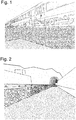
- Figur 1:
- Eine abgestochene, durch vorgängige Verklebung stabilisierte Schottertrasse, an welcher gerade ein Zug vorbeifährt;
- Figur 2:
- Eine abgestochene stabilisierte Schottertrasse längs eines Schienenstranges vor einem Tunnelportal;
- Figur 3:
- Eine Einrichtung zum Austragen von Klebstoff aus drei Wagen in einer schematischen Darstellung von oben gesehen;
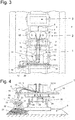
- Figur 4:
- Diese Einrichtung auf ihre Front gesehen, das heisst auf die Front des Sprühwagens gesehen, in einem schematischen Aufriss dargestellt;
- Figur 5:
- Das Blockschema der Mittel für das Pumpen und Zusammenmischen der Komponenten zu einem sprühfähigen Gemisch auf dem Sprühwagen;
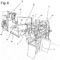
- Figur 6:
- Eine Einrichtung, bestehend aus drei Wagen, in perspektivischer Ansicht dargestellt, mit Blick auf den Sprühwagen ganz vorne, den daran anschliessenden Behälterwagen und zuhinterst den Energieversorgungswagen;
- Figur 7:
- Den Sprühwagen von schräg hinten gesehen;
- Figur 8:
- Den Sprühwagen von vorne gesehen;
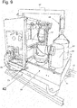
- Figur 9:
- Einen Kombiwagen für die Energieversorgung und das Mitführen der Behälter, zur Bildung einer zweiteiligen Komposition zusammen mit einem Sprühwagen;
- Figur 10:
- Eine Einrichtung, bestehend aus drei Wagen, beim Verladen in einen Anhänger;
- Figur 11:
- Eine geeignete Fahrzeug-Anhänger Komposition für den Strassentransport der gesamten Einrichtung und des Personals;
- Figur 12:
- Ein Fahrzeug mit Anhänger und der Einrichtung darin, bestehend aus drei Wagen, in einer schematischen Darstellung von oben gesehen, beim Heranfahren mit dem Zugfahrzeug und Anhänger an einen Schienenweg an der Stelle eines Bahnüberganges der Strasse, und hernach das Aufsetzen der drei Wagen auf die Schienen;
- Figur 13:
- Die Frontseite des Sprühwagens mit seinem Sprühbalken, wenn dieser Sprühwagen auf einem Schienenstrang steht und die Schienentrasse besprüht;
- Figur 14:
- Eine Komposition aus zwei Wagen, nämlich einem Energieversorgungswagen sowie einem Sprüh- und Behälterwagen, im Einsatz auf einem Schienenstrang;
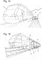
- Figur 15:
- Einen Blick auf die Front der Komposition bei der Arbeit, und daneben auf dem Nebengleis eine vorbeifahrende Lokomotive;
- Figur 16:
- Einen perspektivischen Blick auf die Komposition von schräg hinten, mit auf dem Nebengleis vorbeifahrendem Zug;
- Figur 17:
- Ein schienenfähiges Strassenfahrzeug, auf dem alle Elemente für die elektrische Energieversorgung und Steuerung für das Pumpen mittels Zahnradpumpen, für das Mischen und kontrollierte Austragen der Komponenten eines Mehrkomponentenklebstoffes über den vorne angebauten Sprühbalken vorhanden sind.
- Figure 1:
- A cut gravel road, stabilized by previous gluing, on which a train is just passing;
- Figure 2:
- A cut stabilized gravel road along a track in front of a tunnel portal;
- Figure 3:
- A device for dispensing adhesive from three cars in a schematic representation seen from above;
- Figure 4:
- This device seen on its front, that is, seen on the front of the spray truck, shown in a schematic elevation;
- Figure 5:
- The block diagram of the means for pumping and mixing the components into a sprayable mixture on the spray truck;
- Figure 6:
- A facility consisting of three cars, shown in perspective, with a view of the spray car at the front, the then the container wagon and at the back the energy supply wagon;
- Figure 7:
- The spray truck seen obliquely from behind;
- Figure 8:
- The sprayer seen from the front;
- Figure 9:
- A combination wagon for the energy supply and carrying the containers, to form a two-part composition together with a spray wagon;
- Figure 10:
- A facility consisting of three wagons when loaded onto a trailer;
- Figure 11:
- A suitable vehicle-trailer composition for the road transport of the entire facility and the staff;
- Figure 12:
- A vehicle with a trailer and the equipment in it, consisting of three cars, seen in a schematic representation from above, when approaching the towing vehicle and trailer to a railroad track at the point of a level crossing of the street, and then placing the three cars on the rails ;
- Figure 13:
- The front of the spray car with its spray bar when this spray car is on a rail track and sprays the rail route;
- Figure 14:
- A composition of two cars, namely an energy supply car and a spray and container car, in use on a rail track;
- Figure 15:
- A look at the front of the composition at work, and a locomotive passing by on the siding;
- Figure 16:
- A perspective view of the composition diagonally from behind, with the train passing on the siding;
- Figure 17:
- A rail-capable road vehicle, on which all elements for the electrical power supply and control for pumping by means of gear pumps, for mixing and controlled discharge of the components of a multi-component adhesive are present via the spray bar attached at the front.
In
Die
Die
Und so zeigt die
Die selbstfahrende Einheit, das heisst der Sprühwagen 1, ist in
Die
Über weitere Signalleitungen 39, 40 zwischen der Steuereinheit 34 und den beiden Pneumatikventilen 19, 20 lassen sich diese öffnen und schliessen. Hinter den Pneumatikventilen 19, 20 folgt je ein Rückschlagventil 27, 28. Zwischen der Steuereinheit 34 und dem 24V-Fahrmotor 25 existiert eine weitere Signalleitung 41, welche eine Steuerung der Geschwindigkeit des Sprühwagens 1 ermöglicht. Die Steuereinheit 34 verfügt über eine Mikroprozessorsteuerung mit einem Speicher und einer Recheneinheit. Im Speicher können beispielsweise über die Bedieneinheit oder eine Eingabeschnittstelle die einzuhaltenden Mischverhältnisse zwischen den Komponenten A und B, die gewünschten Durchflussraten bzw. Gesamtdurchflussraten und die Geschwindigkeit des Sprühwagens 1 als Sollwerte eingegeben und abgelegt werden. Die Recheneinheit ist dabei so programmiert, dass sie ein Regelungsprogramm abarbeitet, welches gewährleistet, dass die Mischverhältnisse zwischen den Komponenten A und B und die Durchflussraten bis auf wenige Prozent genau eingehalten werden. Bei grösseren Abweichungen wird die Austragung der Komponenten A und B automatisch gestoppt.These can be opened and closed via
So kann z.B. zwischen den beiden Zahnradpumpen 11, 12 je ein Überdruckventil in die Zuführleitungen 9, 10 integriert werden und der Ausgang der Überdruckventile kann mit Rückleitungen ausgestattet werden, mit welchen eine bei geöffnetem Überdruckventil austretende fluidförmige Komponente A bzw. B in einen zugehörigen Abschnitt der Zuleitung vor der zugehörigen Zahnradpumpe 11 bzw. der Zahnradpumpe 12 zurückgeführt werden kann. Prinzipiell können die Massendurchfluss-Messgeräte 15, 16 auch weggelassen werden und stattdessen können zusätzliche Lagegeber an den Zahnradpumpen 11, 12 und/oder den zugehörigen Antrieben 13, 14 vorgesehen werden.For example, a pressure relief valve can be integrated into the
Wie im Blockschema nach
In
Im zweiten Anhänger, dem Energieversorgungswagen 3 mit einem Gewicht in der Grössenordnung von 350 kg ist ein Dieselmotor und zuschaltbarer stromerzeugender Dieselgenerator mit 400 V Ausgangsspannung untergebracht, sowie eine Drucklufterzeugungsanlage mit Druckluftbehälter, deren Kompressor ebenfalls vom Dieselmotor antreibbar ist, und weitere Hilfsmittel zum Betrieb der Einrichtung. Strom und Druckluft werden von diesem Energieversorgungswagen 3 über nicht gezeigte Leitungen über den Behälterwagen 2 nach vorne zum Sprühwagen 1 geleitet. Elektrische Energie wird u.a. zum Fahren der Wagen mittels der 24V-Fahrmotoren benötigt. Die Sekundärantriebe für die Wagenräder können zum Beispiel Kettenantriebe oder Zahnriemen sein. Mit Elektromotoren werden auch die Zahnradpumpen auf dem Sprühwagen angetrieben und wahlweise kann auch die Heizung auf dem Behälterwagen 2 eine elektrische sein. Weiter benötigt die Steuereinheit 34, die entweder auf dem Energieversorgungswagen 3 oder auf dem Sprühwagen 1 untergebracht ist, elektrischen Strom. Diese Steuereinheit 34 verarbeitet die Signale der Massendurchfluss-Messer und aller übrigen Sensoren, etwa von jenen für das Messen der Fahrgeschwindigkeit und vom Thermometer auf dem Behälterwagen 2. Sie generiert daraus Steuersignale für die Zahnradpumpen, für die pneumatischen Sicherheits-Ventile bei den Sprühdüsen und für die Antriebsmotoren für das Fahren sowie für die Heizung und Kühlung der Komponenten A, B. Druckluft wird für die pneumatischen Sicherheits-Ventile benötigt, sowie für allfällige Druckluftwerkzeuge am Energieversorgungswagen 3. Dieser kann nämlich in einen Arbeitsplatz ausgestaltet sein, mit einer Arbeitsfläche 57 wie die einer Werkbank, und mit allerlei Werkzeugen für irgendwelche möglichen Service- und Reparaturarbeiten, die nötig werden könnten. Man erkennt in der
Die
In
Anstatt die Einrichtung in drei separate Wagen zu unterteilen wie eben vorgestellt, kann auch eine Ausführung mit bloss zwei Wagen umgesetzt werden. In diesem Fall werden zum Beispiel der Behälterwagen 2 und der Energieversorgungswagen 3 in einen einzelnen Wagen 42 zusammengefasst, wie in
Andererseits ist die Komposition auch so aufteilbar, dass der Sprühwagen 1 gleichzeitig die Behälter für die beiden Komponenten A, B aufnimmt, und der zweite Wagen einzig der Energieversorgung dient, das heisst der Stromerzeugung und Drucklufterzeugung und -versorgung, sowie mit seiner Arbeitsfläche 57 als Werkstattwagen dient.On the other hand, the composition can also be divided so that the
Die Unterteilung in diese entweder zwei 1, 42 oder drei Wagen 1, 2 und 3 ist der Schlüssel für die Flexibilität der Einrichtung, damit sie mit einem Strassenfahrzeug zum Einsatzort gebracht werden können. Dank der Unterteilung in zwei oder drei ungefähr gleichschwere Wagen lässt sich das Gesamtgewicht der Einrichtung in jedem Fall von bloss zwei Personen umschlagen. Damit lässt sich die Einrichtung sogar auf 3.5 Tonnen Fahrzeugen auf der Strasse transportieren und am Einsatzort wieder von bloss zwei Personen auf die Schienen eines Eisenbahn-Schienenstranges aufsetzen und in Betrieb nehmen.The division into either two 1, 42 or three
Für ganz lange zu verklebende Strecken lässt sich ein grosser Tankwagen in Form eines Güterwagens mit einer Mehrzahl darauf abgestellter grosser Behälter als hinterster Wagen nachziehen. Aus diesem Eisenbahnwagen führen dann Zufuhrleitungen in den Behälterwagen und seine Behälter 60, 61, die dann als Puffer dienen, zum Vorheizen der Komponenten auf die ideale Temperatur. Für solche Einsätze ist es vorteilhaft, wenn alle zwei oder drei Wagen der Einrichtung als selbstfahrende Wagen ausgeführt sind, also je ihre Räder mittels Elektromotoren antreibbar sind. Mit Vorteil wird die Geschwindigkeit zwischen den verschiedenen selbstfahrenden Wagen mit der Fahrgeschwindigkeit der Rangierlok synchronisiert. Der Strom hierfür wird vom 400V-Generator auf dem Energieversorgungswagen 3 bereitgestellt. Bei einer ganz grossen Menge an mitgeführten Klebstoff-Komponenten auf einem langen Güterwagen muss die Einrichtung evtl. von einer separaten Rangierlok geschoben werden. Der beschriebene Geschwindigkeitssensor 43 stellt sicher, dass der Durchsatz der beiden fluidförmigen Komponenten in Abhängigkeit der jeweils aktuellen Geschwindigkeit des Fahrzeugs exakt geregelt wird. Geschwindigkeitsänderungen einer allfälligen zusätzlichen Rangierlok können damit ausgeglichen werden. Der Sprühwagen mit seinen Pumpen erlaubt es, ca. 21 m3 Gleis-Schotter pro Stunde zu verkleben. Wenn auf dem Behälterwagen oder auf mitgezogenen Eisenbahnwagen zum Beispiel 6'000 Liter Klebstoff-Gemisch mitgefahren werden, so kann die Maschine 19 Stunden am Stück arbeiten und dabei 400m3 Gleis-Schotter perfekt und gleichmässig verkleben.For very long distances to be glued, a large tank truck in the form of a freight car with a plurality of large containers placed on it can be drawn as the rear car. From this railroad car supply lines then lead into the tank car and its
Anhand von
Die
Die
In
In
In
In
Beim Auftragen des Zweikomponentenklebstoffs mit der erfindungsgemässen Einrichtung konnten qualitativ hochstehende Verklebungen mit wohldefinierter Breite und Tiefe hergestellt werden. Untersuchungen an erfindungsgemäss verfestigtem bzw. verklebtem Gleisschotter haben gezeigt, dass diese kaum Fehlstellen enthalten und weitaus besser halten als herkömmlich behandelter Gleisschotter. Das führt sogar dazu, dass dieses Ausbringungsverfahren von den Schweizerischen Bundesbahnen zertifiziert wurde, und daher auch von Versicherungen anerkannt wird, das heisst wenn es sachgemäss zum Einsatz kommt, können damit verklebte Trassen normal befahren werden, auch wenn sie seitlich abgestochen und ohne Verklebung niemals mehr für eine Befahren mit Zügen stabil genug wären.When applying the two-component adhesive with the device according to the invention, high-quality bonds with well-defined width and depth could be produced. Investigations on track ballast consolidated or bonded according to the invention have shown that these contain hardly any imperfections and hold much better than conventionally treated track ballast. This even means that this application process has been certified by the Swiss Federal Railways and is therefore also recognized by insurance companies, which means that if it is used properly, it can be used to run along glued paths even if they are cut off to the side and would never be stable enough to be used by trains without gluing.
Die
Zusammenfassend ist festzustellen, dass diese Einrichtung zum Austragen eines Mehrkomponentenklebstoff gegenüber der gebräuchlichen Applikation von Hand insbesondere bei der Verklebung oder Verfestigung von Schotter bei Eisenbahnanlagen enorme Vorteile mit sich bringt. Insbesondere lässt sie sich höchst flexibel einsetzen, indem sie einfach auf der Strasse an Ort und Stelle transportierbar ist, dort durch bloss zwei Personen auf die Schiene aufsetzbar ist, und hernach ermöglicht sie, die Ausbringungsgeschwindigkeit des Mehrkomponentenklebstoffs massiv zu steigern und die Qualität der Verklebung von Gleisschotter stark zu verbessern.In summary, it can be stated that this device for dispensing a multi-component adhesive has enormous advantages over the customary application by hand, in particular when bonding or consolidating ballast in railway systems. In particular, it can be used in a highly flexible manner by simply being transported on the road to the place where it can be put on the rail by just two people, and afterwards it enables the application speed of the multicomponent adhesive to be increased massively and the quality of the bonding of Track ballast to improve greatly.
- 11
- SprühwagenSpray truck
- 22nd
- BehälterwagenContainer wagons
- 33rd
- EnergieversorgungswagenPower supply car
- 44th
- Eisenbahnschienen, GleisRailroad tracks, track
- 55
- BahnschwellenRailway sleepers
- 66
- SchotterbettBallast bed
- 77
- Kupplungsdeichsel zwischen 1 und 2Coupling drawbar between 1 and 2
- 88th
- Kupplungsdeichsel zwischen 2 und 3Coupling drawbar between 2 and 3
- 99
- Erste Zufuhrleitung für Komponente AFirst supply line for component A
- 1010th
- Zweite Zufuhrleitung für Komponente BSecond supply line for component B
- 1111
- Erste Zahnradpumpe für Komponente AFirst gear pump for component A
- 1212
- Zweite Zahnradpumpe für Komponente BSecond gear pump for component B
- 1313
- Elektromotor, Antrieb für 11Electric motor, drive for 11
- 1414
- Elektromotor, Antrieb für 12Electric motor, drive for 12
- 1515
- Massendurchfluss-Messgerät für Komponente AMass flow meter for component A
- 1616
- Massendurchfluss-Messgerät für Komponente BMass flow meter for component B
- 1717th
- SprühbalkenSpray bar
- 1818th
- Ausleger für SprühbalkenBoom for spray bars
- 1919th
- Pneumatik-Sicherheitsventil für Komponente APneumatic safety valve for component A
- 2020th
- Pneumatik-Sicherheitsventil für Komponente BPneumatic safety valve for component B
- 2121st
- Steine des SchotterbettesStones of the ballast bed
- 2222
- Fahrgestellchassis
- 2323
- Achse des FahrgestellsChassis axis
- 2424th
- Rad des FahrgestellsWheel of the chassis
- 2525th
- 24V-Fahrmotor24V drive motor
- 2626
- Y-förmiger FittingY-shaped fitting
- 2727th
- Rückschlagventil für Komponente ACheck valve for component A
- 2828
- Rückschlagventil für Komponente BCheck valve for component B
- 2929
- WendelmischerSpiral mixer
- 3030th
- SprühdüsenSpray nozzles
- 3131
- SprühbildSpray pattern
- 3232
- SprühbereichSpray area
- 3333
- Fluid-AustrittsseiteFluid outlet side
- 3434
- SteuereinheitControl unit
- 3535
-
Steuerleitung für Elektromotor 13Control line for
electric motor 13 - 3636
-
Steuerleitung für Elektromotor 14Control line for
electric motor 14 - 3737
- Signalleitung von Massendurchfluss-Messgerät für Komponente ASignal line from mass flow meter for component A
- 3838
- Signalleitung Massendurchfluss-Messgerät für Komponente BSignal line mass flow meter for component B
- 3939
-
Signalleitung von Steuereinheit 34 zu Pneumatikventil 19Signal line from
control unit 34 topneumatic valve 19 - 4040
-
Signalleitung von Steuereinheit 34 zu Pneumatikventil 20Signal line from
control unit 34 topneumatic valve 20 - 4141
-
Steuerleitung für Fahrmotor 42Control line for
traction motor 42 - 4242
- Einziger Wagen für Behälter und EnergieversorgungThe only cart for containers and energy supply
- 4343
- FahrgeschwindigkeitssensorDriving speed sensor
- 4444
- Singalleitung Fahrgeschwindigkeitssensor zu SteuereinheitSignal line travel speed sensor to control unit
- 4545
- Sensor für die Beschaffenheit des zu besprühenden BereichsSensor for the nature of the area to be sprayed
- 4646
-
Signalleitung von Sensor 45 an die Steuereinheit 34Signal line from
sensor 45 to controlunit 34 - 4747
- Blenden links und rechts des Sprühbalkens, in Form von GummimattenPanels on the left and right of the spray bar, in the form of rubber mats
- 4848
- Anhängerpendant
- 4949
- TandemachseTandem axle
- 5050
- Schienen im Innern des AnhängersRails inside the trailer
- 5151
- ausziehbare oder ausschenkbare Schienen am Anhängerpull-out or swing-out rails on the trailer
- 5252
- Seilwinde am AnhängerWinch on the trailer
- 5353
- ZugfahrzeugTowing vehicle
- 5454
- Behälter auf dem GüterwagenContainers on the freight wagon
- 5555
- RangierlokShunting locomotive
- 5656
- AuffangwannenSumps
- 5757
- Arbeitsfläche, WerkbankWork surface, workbench
- 5858
- Sieb für das KlebstoffgemischSieve for the adhesive mixture
- 5959
- DruckluftbehälterCompressed air tank
- 6060
- Erster Behälter für Komponente AFirst container for component A
- 6161
- Zweiter Behälter für Komponente BSecond container for component B
- 6262
- Krafthebel zum Anheben des SprühwagensPower lever for lifting the spray truck
- 6363
-
Drehrad für den Krafthebel 62Rotary wheel for
power lever 62 - 6464
- Lasthebel zum Anheben des SprühwagensLoad lever for lifting the sprayer
- 6565
- Stützrad zum Anheben des SprühwagensJockey wheel for lifting the sprayer
- 6666
-
Verbindungsachse zwischen den beiden Stützrädern 65Connection axis between the two
support wheels 65 - 6767
- KranauslegerCrane boom
- 6868
- FlaschenzugPulley
- 6969
- Schalttableau für Generator, DieselmotorSwitch panel for generator, diesel engine
- 7070
- Belüftungsrohr für Ventilator zur AuffangwanneVentilation pipe for fan to the sump
- 7171
- Schienenfähiges StrassenfahrzeugRail-capable road vehicle
- 7272
- SchienenräderRail wheels
- 7373
- PneuräderTire wheels
Claims (15)
- A device for transporting multi-component adhesives of at least two fluidic components (A, B) as well as all necessary elements for spreading them from separately stored components (A, B) to a granular ballast bed (6) of a railway track (4) at a site of use, and for carrying along and discharging these multi-component adhesives at the site of use onto the granular ballast bed (6) of the railway stretch of rails (4) there,
characterized in that
said device is both road transportable and rail-suitable by comprising either a rail-suitable road vehicle (71) or at least one road-transportable rail vehicle (1, 2, 3) with a road vehicle (53) or road trailer (58) belonging to the device for its transport by road, with in both cases gauge-changeable rail wheels (72, 24), and wherein this road or rail vehicle comprises all necessary elements for the electric power supply and control for pumping the components (A, B) by means of gear pumps, for their mixing and for their controlled discharge as multi-component adhesive via a spray unit belonging to the device, which has a spray bar (17) and is mounted on one of the vehicles (71, 1), which serves as spray wagon, and which spray bar (17) can be supplied with these components (A, B), and these components (A, B) being pumpable from at least two separate containers (60, 61) which can be carried in associated catch bins (56) on the rail-suitable road vehicle (71) or on one of the road-transportable rail vehicle (2) of the device, wherein the components (A, B) are pumpable via associated flexible hose lines (9, 10) each by a gear pump and a mass flow meter (15, 16) to a mixer (29) and then to this spray bar (17) on the device, and which spray bar (17) of the spray unit is horizontally and vertically movable in an automatically controlled motor-driven manner at the spray wagon and mounted rotatable in all directions on a cantilever (18), which extends across the vehicle width of the spraying wagon, for the speed-dependent controlled spreading of the adhesive mixture in a plurality of selectable spray patterns. - A device for discharging multi-component adhesives of at least two fluidic components (A, B) from separately stored components (A, B) onto a granular ballast bed (6) of a railway stretch of rails (4)
characterized in that
the device comprises at least two wagons (1, 2, 3) drivable on rails (4, 52, 53) with gauge-changeable rail wheels (24), said wagons being road-transportable in their entirety in a single road vehicle (53) or road trailer (48), which can be coupled using drawbars (7, 8) in a tension-locking manner and can be connected to hoses and cables for their functional interaction, wherein one of the wagons (1, 2, 3) is designed as a spray wagon (1) and contains all necessary elements for the pumping, mixing and controlled discharging of the components (A, B) via flexible hose lines (9, 10) to a spray unit having a spray bar (17), and a further wagon (2) or optionally an additional third wagon (3) belonging to the device contains all further elements, namely two separate containers (60, 61), which stand in catch basins (56), containing the transportable fluidic components (A, B) to be used and mixed, and a diesel power generator with 400 V for the power supply and a control unit (34) for the electric control, and further that the device includes an associated vehicle (53, 48), comprising a downwardly tiltable loading area in the rear, on which loading area rails (50, 51) are extendable to the rear beyond the end of the loading area, so that the wagons (1, 2, 3) can be pulled onto the loading area on these rails (50, 51) and can be place down in the opposite direction onto the tracks of a stretch of rails (4). - The device (10) according to claim 1,
characterized in that
the device consists of at least two separate wagons (1, 58) drivable on rails with gauge-changeable rail wheels (24), said wagons being road-transportable in their entirety in a single road vehicle (53) or road trailer (48), which can be coupled using a drawbar (7) in a tension-locking manner and can be connected to hoses and cables for their functional interaction, wherein the first wagon is designed as a spray wagon (1) and contains all necessary elements for the pumping, mixing and controlled discharging of the components (A, B) via flexible hose lines (9, 10) belonging to the device to the spray unit, and the second wagon (42) is equipped as a tank wagon, having catch basins (56) for inserting and heating the separate containers (60, 61) with the fluidic components (A, B) to be used and mixed, as well as for the power supply with a diesel power generator and its starter battery and a control unit (34) for the electric control of all electrically operated components. - The device (10) according to claim 1,
characterized in that
the device consists of at two separate wagons (1, 58) drivable on rails and having gauge-changeable rail wheels (24), said wagons being road-transportable in their entirety in an associated single road vehicle (53) or road trailer (48), which drivable wagons (1, 48) can be coupled using a drawbar (7) in a tension-locking manner and can be connected to hoses and cables for their functional interaction, wherein the first wagon is designed as a container (2) and spray wagon (1) having catch basins (56) for inserting and heating the separate containers (60, 61) with the fluidic components (A, B) to be used and mixed as well as all equipped with all necessary elements for the pumping, mixing and controlled discharging of the components (A, B) from the containers (60, 61) via flexible hose lines (9, 10) by means of a spray unit, and the second wagon is equipped with a diesel power generator for the power supply having its starter battery and a control unit (34) for the electric control of all electrically operated components. - The device (10) according to claim 1,
characterized in that
the device consists of at three separate wagons (1, 2, 3) drivable on rails (4, 50, 51) and having gauge-changeable rail wheels (24), said wagons being road-transportable in their entirety in an associated single road vehicle (53) or road trailer (48), which can be coupled in a tension-locking manner using drawbars (7, 8) and can be connected to hoses and cables for their functional interaction, wherein the first wagon is designed as a spray wagon (1) and contains all necessary elements for the pumping, mixing and controlled discharging of the components (A, B) via flexible hose lines (9, 10) to a spray unit, the second wagon is designed as a container wagon (2), having catch basins (56) for inserting and heating the separate containers (60, 61) with the fluidic components (A, B) to be used and mixed, and the third wagon is equipped as a power supply wagon (3) the power supply with a diesel power generator having its starter battery and a control unit (34) for the electric control of all electrically operated components. - The device according to any of the preceding requirements,
characterized in that
the spray unit on the spraying wagon (1) has a spraying bar (17) running transversely to the direction of travel of the wagon on the outside of this spraying wagon (1), which is horizontally and vertically moveable by motor control and mounted rotatable in all directions on a cantilever (18) which extends transversely beyond the width of the spraying wagon (1) and has a plurality of nozzles (30) for creating different spray patterns (31), and the container wagon (2) has a self-regulating heater for the interior of the catch basins (56), for maintaining the components (A, B) at a set temperature, and that batteries are provided for temporarily storing electric power, and that the control unit (34) is programmable in memory, is designed for different application programs and for supplying and controlling the heating device, the gear pumps (11, 12) for the components (A, B), the movement of the spray nozzles (30) and the control devices with their sensors (43, 45). - The device according to any the preceding claims,
characterized in that
the associated road vehicle (53) for transport the device by road is a self-propelled low-bed vehicle transporter or a double-axle road trailer (48) having a loading area for vehicle transport and steel cable winch (52), wherein the loading area is electrically or hydraulically downwardly inclinable to the rear and rails (50, 51) are arranged on the loading area, and wherein further rails (51) are extendable or pivotable to the rear beyond the loading area in an inclined position of the loading area as far as possible, that their rear ends are supported on the floor or on the rails (4) of a stretch of rails running on the ground, whereby the wagons (1, 2, 3) can be pulled on the loading area over the rails (51) by their rail wheels (24) into the trailer (48) by means of the steel cable winch (52) and can be lowered in the opposite direction onto a stretch of rails on the ground. - The device according to any of the preceding claims,
characterized in that
the spraying wagon (1) comprises feed lines (9, 10) for conveying the fluidic components (A, B) as well as a mixer unit (29) for mixing the fluidic components (A, B) to form an adhesive mixture, and wherein both feed lines (9, 10) are equipped with a controllable gear pump (11, 12) for controlling the flow rate and with a mass flow meter (15, 16) for the respective fluidic component (A, B) through the respective feed line (9, 10) and the control unit (34) is designed such that a total flow rate and/or a mixing ratio between the fluidic components (A, B) can be maintained on the basis of the recorded flow rates via at least one output variable. - The device according to any of claims from 1 to 6,
characterized in that
the control unit (34) is designed such that the total delivery rate and the mixing ratio between the fluidic components (A, B) can be regulated with said control unit via at least two output variables. - The device according to any of the preceding claims,
characterized in that
the control unit (34) is designed such that the flow rates of the two fluidic components (A, B) can be controlled as a function of the travel speed by determining them by means of the travel speed sensor (43) of the spraying wagon (1). - The device according to any of the preceding claims,
characterized in that
the spray bar (17) comprises a several nozzles (30) which can optionally be fed to produce a flat, curtain-like or conical spray pattern (31). - The method for operating a device according to any of the preceding claims,
characterized in that
the rail-compatible road vehicle is self-propelled or the separate carriages (1, 2, 3) are transported by road on a single vehicle or trailer (48) to the place of use, and there the rail-compatible road vehicle is driven onto the rail line and put into operation, or the road vehicle is brought into operation, the road trailer (48) is brought into position on the rail line and the carriages (1, 2, 3) are then set down on the rails (4) of a rail line to be treated and afterwards coupled together in a force-locking and hinged manner by means of drawbars (7, 8) and are put into operation the automatically controlled pumping, mixing and discharge of the adhesive. - The method according to claim 11,
characterized in that
while the adhesive is being discharged, the flow rates of the fluidic components are detected by continuously measuring the flow rates in the control unit (34) of the device and compared by comparing the measured data with a defined setpoint and at least one output variable, in particular with an output signal for controlling the total delivery rate of the gear pumps (11, 12) and/or the mixing ratio of the fluidic components (A, B) for continuously monitoring the discharge. - The method according to any of claims 11 to 12,
characterized in that
the ratio of the flow rates of the fluidic components (A, B) is controlled by continuous comparison with a ratio setpoint stored in the control unit (34), and the first and/or the second output variable is adapted by the control unit (34) as a function of the difference between the determined ratio and the ratio setpoint, and the output value is used to control the gear pumps (11, 12) and their flow rates, or that in the event of a deviation of the determined flow rates and/or a deviation of the ratio of the determined flow rates by more than a predetermined maximum value of a deviation, the discharge and/or conveying of the fluidic components (A, B) is automatically stopped by the control unit (34) by stopping the gear pumps (11, 12) and closing the pneumatic valves (19, 20). - The use of the device according to any of claims 1 to 10 for transporting the device to its place of use, driving up the railway-compatible vehicle or setting down the rail wagons (1, 2, 3) from the road vehicle (54) or road trailer (58) onto the stretch of rails (4) of the rail track to be treated and for discharging multi-component adhesives having at least two fluidic components (A, B) onto the ballast bed (6) of this rail track in order to bond it in sections over the entire track width or over part of the track width.
Priority Applications (8)
| Application Number | Priority Date | Filing Date | Title |
|---|---|---|---|
| SI201730333T SI3445596T1 (en) | 2016-04-19 | 2017-04-19 | Device for discharging multi-component adhesives onto a granular mixture, discharging method, and use of the device |
| PL17726109T PL3445596T3 (en) | 2016-04-19 | 2017-04-19 | Device for discharging multi-component adhesives onto a granular mixture, discharging method, and use of the device |
| RS20200840A RS60549B1 (en) | 2016-04-19 | 2017-04-19 | Device for discharging multi-component adhesives onto a granular mixture, discharging method, and use of the device |
| DK20181726.9T DK3738800T3 (en) | 2016-04-19 | 2017-04-19 | DEVICE FOR APPLICATION OF MULTI-COMPONENT ADHESIVES IN A GRAIN MIXTURE AND PROCEDURE FOR APPLICATION AND USE OF THE DEVICE |
| EP20181726.9A EP3738800B1 (en) | 2016-04-19 | 2017-04-19 | Apparatus for dispensing multicomponent adhesives onto a granular mixture, and method of dispensing and using the apparatus |
| PL20181726T PL3738800T3 (en) | 2016-04-19 | 2017-04-19 | Apparatus for dispensing multicomponent adhesives onto a granular mixture, and method of dispensing and using the apparatus |
| EP21213834.1A EP3995217A1 (en) | 2016-04-19 | 2017-04-19 | Device for dispensing multicomponent adhesives onto a granular mixture, method of dispensing and use of the device |
| HRP20201454TT HRP20201454T1 (en) | 2016-04-19 | 2020-09-11 | Device for discharging multi-component adhesives onto a granular mixture, discharging method, and use of the device |
Applications Claiming Priority (2)
| Application Number | Priority Date | Filing Date | Title |
|---|---|---|---|
| CH00515/16A CH712375A1 (en) | 2016-04-19 | 2016-04-19 | Apparatus and method for discharging multicomponent adhesives to a granular mixture. |
| PCT/EP2017/059253 WO2018010860A1 (en) | 2016-04-19 | 2017-04-19 | Device for discharging multi-component adhesives onto a granular mixture, discharging method, and use of the device |
Related Child Applications (2)
| Application Number | Title | Priority Date | Filing Date |
|---|---|---|---|
| EP21213834.1A Division EP3995217A1 (en) | 2016-04-19 | 2017-04-19 | Device for dispensing multicomponent adhesives onto a granular mixture, method of dispensing and use of the device |
| EP20181726.9A Division EP3738800B1 (en) | 2016-04-19 | 2017-04-19 | Apparatus for dispensing multicomponent adhesives onto a granular mixture, and method of dispensing and using the apparatus |
Publications (2)
| Publication Number | Publication Date |
|---|---|
| EP3445596A1 EP3445596A1 (en) | 2019-02-27 |
| EP3445596B1 true EP3445596B1 (en) | 2020-06-24 |
Family
ID=56119251
Family Applications (3)
| Application Number | Title | Priority Date | Filing Date |
|---|---|---|---|
| EP17726109.6A Active EP3445596B1 (en) | 2016-04-19 | 2017-04-19 | Device for discharging multi-component adhesives onto a granular mixture, discharging method, and use of the device |
| EP21213834.1A Pending EP3995217A1 (en) | 2016-04-19 | 2017-04-19 | Device for dispensing multicomponent adhesives onto a granular mixture, method of dispensing and use of the device |
| EP20181726.9A Active EP3738800B1 (en) | 2016-04-19 | 2017-04-19 | Apparatus for dispensing multicomponent adhesives onto a granular mixture, and method of dispensing and using the apparatus |
Family Applications After (2)
| Application Number | Title | Priority Date | Filing Date |
|---|---|---|---|
| EP21213834.1A Pending EP3995217A1 (en) | 2016-04-19 | 2017-04-19 | Device for dispensing multicomponent adhesives onto a granular mixture, method of dispensing and use of the device |
| EP20181726.9A Active EP3738800B1 (en) | 2016-04-19 | 2017-04-19 | Apparatus for dispensing multicomponent adhesives onto a granular mixture, and method of dispensing and using the apparatus |
Country Status (19)
| Country | Link |
|---|---|
| US (2) | US20190118207A1 (en) |
| EP (3) | EP3445596B1 (en) |
| JP (1) | JP6906241B2 (en) |
| CN (1) | CN109070670B (en) |
| AU (2) | AU2017294925B9 (en) |
| CA (1) | CA3021427C (en) |
| CH (2) | CH712375A1 (en) |
| CY (1) | CY1123235T1 (en) |
| DK (2) | DK3738800T3 (en) |
| EA (1) | EA038480B1 (en) |
| ES (2) | ES2808095T3 (en) |
| HR (2) | HRP20220402T1 (en) |
| HU (2) | HUE058117T2 (en) |
| LT (1) | LT3445596T (en) |
| PL (2) | PL3445596T3 (en) |
| PT (2) | PT3445596T (en) |
| RS (2) | RS60549B1 (en) |
| SI (2) | SI3738800T1 (en) |
| WO (1) | WO2018010860A1 (en) |
Families Citing this family (9)
| Publication number | Priority date | Publication date | Assignee | Title |
|---|---|---|---|---|
| DE102015105553A1 (en) * | 2015-04-12 | 2016-10-13 | ATN Hölzel GmbH | Method for producing a load-optimized adhesive bond |
| CN109941299B (en) * | 2019-04-26 | 2024-03-12 | 中车眉山车辆有限公司 | Movable grounding device for railway wagon |
| DE102019214562A1 (en) * | 2019-09-24 | 2021-03-25 | Hyperion Verwaltung Gmbh | Method for producing a track body |
| CH718156A2 (en) | 2020-12-14 | 2022-06-15 | Huerlimann Railtec Ag | Device and method for dispensing single-component or multi-component adhesive onto a ballast bed of a railway line. |
| CH718160A1 (en) * | 2020-12-15 | 2022-06-15 | Huerlimann Railtec Ag | Process and device for creating the permanent watertightness of a formation protection layer under a ballast bed to be created for track construction. |
| RU205846U1 (en) * | 2021-03-17 | 2021-08-11 | Открытое Акционерное Общество "Российские Железные Дороги" | TRANSPORTATION AND TRACTION MODULE |
| CN113663853B (en) * | 2021-08-30 | 2022-07-19 | 重庆赛帕斯汽车零部件股份有限公司 | Antistatic powder spraying equipment for metal part production and processing |
| CN114183171A (en) * | 2021-11-04 | 2022-03-15 | 中铁隧道局集团建设有限公司 | Concrete curing system for tunnel with super-large section |
| BE1030113B1 (en) | 2021-12-27 | 2023-07-25 | Trafiroad Nv | METHOD AND SPRAY TROLLEY FOR APPLYING A TWO-COMPONENT EPOXY ADHESIVE |
Family Cites Families (25)
| Publication number | Priority date | Publication date | Assignee | Title |
|---|---|---|---|---|
| FR371604A (en) * | 1906-11-19 | 1907-03-12 | Hugo Drucker | Device for transporting railway wagons on non-rail tracks or on railways of different track width |
| DE7210483U (en) * | 1972-03-18 | 1972-09-14 | Ulrich Heinz | DEVICE FOR APPLYING SUBSTANCES TO SURFACES |
| AT353305B (en) * | 1976-09-10 | 1979-11-12 | Plasser Bahnbaumasch Franz | ROAD AND TRACKABLE TAMPING MACHINE |
| US4941408A (en) * | 1988-12-15 | 1990-07-17 | Lovitt Jr Estel L | Adjustable frame for rail wheels on motor vehicles adaptable to ride on railroad tracks |
| ATE105741T1 (en) * | 1989-12-02 | 1994-06-15 | Koch Marmorit Gmbh | METHOD AND APPARATUS FOR THE APPLICATION OF MULTI-COMPONENT RESINS AND APPLICATIONS OF SAME. |
| US5372844A (en) * | 1989-12-02 | 1994-12-13 | Koch Marmorit Gmbh | Process and device of applying multi-component resins and use of same |
| ATE147113T1 (en) * | 1993-03-04 | 1997-01-15 | Plasser Bahnbaumasch Franz | GRAVEL PLASTER |
| US5401312A (en) * | 1993-10-22 | 1995-03-28 | Hanst; Donald R. | Method for soil surface stabilization |
| JPH07292604A (en) * | 1994-04-21 | 1995-11-07 | Osada Giken Kk | Reinforcement of ballast |
| DE19632638A1 (en) * | 1996-08-13 | 1998-02-19 | Klaus Dieter Ihle | Method of applying multi=component resins on granular materials |
| DE19811838A1 (en) * | 1998-03-18 | 1999-09-23 | Max Knape Gmbh & Co Fa | Ballast consolidation equipment especially for consolidating a railroad ballast bed |
| EP1189704B1 (en) * | 1999-06-04 | 2009-07-29 | C-Dax Systems Limited | A spray control device |
| DE10159275A1 (en) * | 2001-12-03 | 2003-06-26 | Stanislaus Schittek | Vehicle capable of travel on roads and on German and Russian railways having different gauges has adjustable steel wheels and rubber tire wheels, and pivot arm ro raise wheels and lift vehicle onto rails |
| US7581684B2 (en) * | 2004-05-25 | 2009-09-01 | Des Garennes Chris | Device for placing material on or beneath the soil surface and method for doing the same |
| US7357427B2 (en) * | 2004-06-25 | 2008-04-15 | Kelsan Technologies Corp. | Method and apparatus for applying liquid compositions in rail systems |
| EA013437B1 (en) * | 2005-02-23 | 2010-04-30 | Франц Плассер Банбаумашинен - Индустригезельшафт М.Б.Х. | Method for a track gauge correction and a track construction machine |
| AU2005100642A4 (en) * | 2005-03-24 | 2005-09-22 | Leon Joseph Caccaviello | Spraying |
| WO2007104710A1 (en) * | 2006-03-15 | 2007-09-20 | Basf Se | Method for fixing traffic routes |
| DE102007057064A1 (en) * | 2007-11-27 | 2009-05-28 | Hennecke Gmbh | Method for strengthening a ballast bed and apparatus for carrying out the method |
| CN102191730B (en) * | 2010-03-09 | 2015-08-26 | 拜耳材料科技(中国)有限公司 | Polyurethane elastomer railway ballast pad and preparation method thereof |
| JP3162597U (en) * | 2010-06-25 | 2010-09-09 | 東鉄工業株式会社 | Rotating base rotation mechanism of railroad vehicle |
| CN101850312A (en) * | 2010-06-29 | 2010-10-06 | 新兴铸管股份有限公司 | Two-component spraying system |
| TW201501784A (en) * | 2013-04-26 | 2015-01-16 | Graco Minnesota Inc | Plural component proportioning system and method |
| US9109332B1 (en) * | 2014-02-25 | 2015-08-18 | Dbi Holding, Llc | Systems and methods for automating the application of friction-modifying coatings |
| CN104118492B (en) * | 2014-07-11 | 2016-06-01 | 江苏海鹏特种车辆有限公司 | Overlength can from handling monoblock type transport trolley |
-
2016
- 2016-04-19 CH CH00515/16A patent/CH712375A1/en not_active Application Discontinuation
-
2017
- 2017-04-19 AU AU2017294925A patent/AU2017294925B9/en active Active
- 2017-04-19 CN CN201780024377.2A patent/CN109070670B/en active Active
- 2017-04-19 HR HRP20220402TT patent/HRP20220402T1/en unknown
- 2017-04-19 ES ES17726109T patent/ES2808095T3/en active Active
- 2017-04-19 ES ES20181726T patent/ES2909830T3/en active Active
- 2017-04-19 PT PT177261096T patent/PT3445596T/en unknown
- 2017-04-19 SI SI201731107T patent/SI3738800T1/en unknown
- 2017-04-19 EP EP17726109.6A patent/EP3445596B1/en active Active
- 2017-04-19 CA CA3021427A patent/CA3021427C/en active Active
- 2017-04-19 RS RS20200840A patent/RS60549B1/en unknown
- 2017-04-19 RS RS20220297A patent/RS63055B1/en unknown
- 2017-04-19 EP EP21213834.1A patent/EP3995217A1/en active Pending
- 2017-04-19 PL PL17726109T patent/PL3445596T3/en unknown
- 2017-04-19 CH CH00520/17A patent/CH712256B1/en unknown
- 2017-04-19 HU HUE20181726A patent/HUE058117T2/en unknown
- 2017-04-19 PL PL20181726T patent/PL3738800T3/en unknown
- 2017-04-19 US US16/093,647 patent/US20190118207A1/en not_active Abandoned
- 2017-04-19 LT LTEP17726109.6T patent/LT3445596T/en unknown
- 2017-04-19 JP JP2018553181A patent/JP6906241B2/en active Active
- 2017-04-19 DK DK20181726.9T patent/DK3738800T3/en active
- 2017-04-19 WO PCT/EP2017/059253 patent/WO2018010860A1/en active Application Filing
- 2017-04-19 HU HUE17726109A patent/HUE051297T2/en unknown
- 2017-04-19 SI SI201730333T patent/SI3445596T1/en unknown
- 2017-04-19 EA EA201800501A patent/EA038480B1/en unknown
- 2017-04-19 DK DK17726109.6T patent/DK3445596T3/en active
- 2017-04-19 PT PT201817269T patent/PT3738800T/en unknown
- 2017-04-19 EP EP20181726.9A patent/EP3738800B1/en active Active
-
2020
- 2020-07-24 CY CY20201100681T patent/CY1123235T1/en unknown
- 2020-09-11 HR HRP20201454TT patent/HRP20201454T1/en unknown
-
2022
- 2022-10-04 AU AU2022246378A patent/AU2022246378B2/en active Active
-
2023
- 2023-10-26 US US18/383,960 patent/US20240082864A1/en active Pending
Non-Patent Citations (1)
| Title |
|---|
| None * |
Also Published As
Similar Documents
| Publication | Publication Date | Title |
|---|---|---|
| EP3445596B1 (en) | Device for discharging multi-component adhesives onto a granular mixture, discharging method, and use of the device | |
| EP1826153B1 (en) | Container way | |
| EP0106239B1 (en) | Maintenance apparatus for bituminous roads | |
| DE202021004316U1 (en) | Device for dispensing single-component or multi-component adhesive onto a granular mixture | |
| DE10005677C2 (en) | Method and device for building routes and dams | |
| DE19726612C2 (en) | Process for handling building materials with trucks and transport equipment | |
| WO2008028307A1 (en) | Method and device for transporting concrete on rails | |
| DE4339833C2 (en) | Construction machine for the new construction, expansion or dismantling of paved traffic routes | |
| DE202008003997U1 (en) | Device for renewing the multi-layer substructure of tracks | |
| WO2022128928A1 (en) | Method and device for sealing the pss layer of a railway route | |
| DE2728001C3 (en) | Transport device for bulk goods, especially for conveying extremely large quantities of fresh concrete to a large construction site | |
| DE19654598A1 (en) | Building materials handling appliance for road construction | |
| EP2904152B1 (en) | System, method and conveyance vehicle for newly producing, repairing or removing a road | |
| AT349990B (en) | TRANSPORT EQUIPMENT FOR THE MAJOR CONTINUOUS TRANSPORT OF SCHUETTGUETERN, ESPECIALLY FRESH CONCRETE | |
| DE7228482U (en) | Concrete paver |
Legal Events
| Date | Code | Title | Description |
|---|---|---|---|
| STAA | Information on the status of an ep patent application or granted ep patent |
Free format text: STATUS: UNKNOWN |
|
| STAA | Information on the status of an ep patent application or granted ep patent |
Free format text: STATUS: THE INTERNATIONAL PUBLICATION HAS BEEN MADE |
|
| PUAI | Public reference made under article 153(3) epc to a published international application that has entered the european phase |
Free format text: ORIGINAL CODE: 0009012 |
|
| STAA | Information on the status of an ep patent application or granted ep patent |
Free format text: STATUS: REQUEST FOR EXAMINATION WAS MADE |
|
| 17P | Request for examination filed |
Effective date: 20181022 |
|
| AK | Designated contracting states |
Kind code of ref document: A1 Designated state(s): AL AT BE BG CH CY CZ DE DK EE ES FI FR GB GR HR HU IE IS IT LI LT LU LV MC MK MT NL NO PL PT RO RS SE SI SK SM TR |
|
| AX | Request for extension of the european patent |
Extension state: BA ME |
|
| DAV | Request for validation of the european patent (deleted) | ||
| DAX | Request for extension of the european patent (deleted) | ||
| RIC1 | Information provided on ipc code assigned before grant |
Ipc: B05B 12/14 20060101ALI20200310BHEP Ipc: E01B 37/00 20060101ALI20200310BHEP Ipc: B60F 1/04 20060101ALI20200310BHEP Ipc: B60F 1/00 20060101AFI20200310BHEP Ipc: B61D 15/00 20060101ALI20200310BHEP Ipc: B05B 12/12 20060101ALI20200310BHEP Ipc: B05B 1/20 20060101ALI20200310BHEP |
|
| GRAP | Despatch of communication of intention to grant a patent |
Free format text: ORIGINAL CODE: EPIDOSNIGR1 |
|
| STAA | Information on the status of an ep patent application or granted ep patent |
Free format text: STATUS: GRANT OF PATENT IS INTENDED |
|
| GRAS | Grant fee paid |
Free format text: ORIGINAL CODE: EPIDOSNIGR3 |
|
| GRAA | (expected) grant |
Free format text: ORIGINAL CODE: 0009210 |
|
| STAA | Information on the status of an ep patent application or granted ep patent |
Free format text: STATUS: THE PATENT HAS BEEN GRANTED |
|
| INTG | Intention to grant announced |
Effective date: 20200504 |
|
| AK | Designated contracting states |
Kind code of ref document: B1 Designated state(s): AL AT BE BG CH CY CZ DE DK EE ES FI FR GB GR HR HU IE IS IT LI LT LU LV MC MK MT NL NO PL PT RO RS SE SI SK SM TR |
|
| REG | Reference to a national code |
Ref country code: GB Ref legal event code: FG4D Free format text: NOT ENGLISH |
|
| REG | Reference to a national code |
Ref country code: CH Ref legal event code: EP |
|
| REG | Reference to a national code |
Ref country code: DE Ref legal event code: R096 Ref document number: 502017005880 Country of ref document: DE |
|
| REG | Reference to a national code |
Ref country code: AT Ref legal event code: REF Ref document number: 1283530 Country of ref document: AT Kind code of ref document: T Effective date: 20200715 |
|
| REG | Reference to a national code |
Ref country code: IE Ref legal event code: FG4D Free format text: LANGUAGE OF EP DOCUMENT: GERMAN |
|
| REG | Reference to a national code |
Ref country code: PT Ref legal event code: SC4A Ref document number: 3445596 Country of ref document: PT Date of ref document: 20200729 Kind code of ref document: T Free format text: AVAILABILITY OF NATIONAL TRANSLATION Effective date: 20200723 |
|
| REG | Reference to a national code |
Ref country code: CH Ref legal event code: NV Representative=s name: FELBER UND PARTNER AG, CH |
|
| REG | Reference to a national code |
Ref country code: HR Ref legal event code: TUEP Ref document number: P20201454 Country of ref document: HR |
|
| REG | Reference to a national code |
Ref country code: FI Ref legal event code: FGE |
|
| REG | Reference to a national code |
Ref country code: DK Ref legal event code: T3 Effective date: 20200914 |
|
| REG | Reference to a national code |
Ref country code: NL Ref legal event code: FP Ref country code: GR Ref legal event code: EP Ref document number: 20200402000 Country of ref document: GR Effective date: 20200916 |
|
| REG | Reference to a national code |
Ref country code: SE Ref legal event code: TRGR |
|
| REG | Reference to a national code |
Ref country code: EE Ref legal event code: FG4A Ref document number: E019566 Country of ref document: EE Effective date: 20200723 |
|
| REG | Reference to a national code |
Ref country code: SK Ref legal event code: T3 Ref document number: E 34897 Country of ref document: SK |
|
| REG | Reference to a national code |
Ref country code: NO Ref legal event code: T2 Effective date: 20200624 |
|
| PG25 | Lapsed in a contracting state [announced via postgrant information from national office to epo] |
Ref country code: AL Free format text: LAPSE BECAUSE OF FAILURE TO SUBMIT A TRANSLATION OF THE DESCRIPTION OR TO PAY THE FEE WITHIN THE PRESCRIBED TIME-LIMIT Effective date: 20200624 |
|
| REG | Reference to a national code |
Ref country code: HR Ref legal event code: T1PR Ref document number: P20201454 Country of ref document: HR |
|
| PG25 | Lapsed in a contracting state [announced via postgrant information from national office to epo] |
Ref country code: SM Free format text: LAPSE BECAUSE OF FAILURE TO SUBMIT A TRANSLATION OF THE DESCRIPTION OR TO PAY THE FEE WITHIN THE PRESCRIBED TIME-LIMIT Effective date: 20200624 |
|
| REG | Reference to a national code |
Ref country code: ES Ref legal event code: FG2A Ref document number: 2808095 Country of ref document: ES Kind code of ref document: T3 Effective date: 20210225 |
|
| REG | Reference to a national code |
Ref country code: HU Ref legal event code: AG4A Ref document number: E051297 Country of ref document: HU |
|
| REG | Reference to a national code |
Ref country code: DE Ref legal event code: R097 Ref document number: 502017005880 Country of ref document: DE |
|
| PLBE | No opposition filed within time limit |
Free format text: ORIGINAL CODE: 0009261 |
|
| REG | Reference to a national code |
Ref country code: HR Ref legal event code: ODRP Ref document number: P20201454 Country of ref document: HR Payment date: 20210414 Year of fee payment: 5 |
|
| STAA | Information on the status of an ep patent application or granted ep patent |
Free format text: STATUS: NO OPPOSITION FILED WITHIN TIME LIMIT |
|
| REG | Reference to a national code |
Ref country code: EE Ref legal event code: HC1A Ref document number: E019566 Country of ref document: EE |
|
| 26N | No opposition filed |
Effective date: 20210325 |
|
| REG | Reference to a national code |
Ref country code: HR Ref legal event code: ODRP Ref document number: P20201454 Country of ref document: HR Payment date: 20220413 Year of fee payment: 6 |
|
| PG25 | Lapsed in a contracting state [announced via postgrant information from national office to epo] |
Ref country code: AL Free format text: LAPSE BECAUSE OF FAILURE TO SUBMIT A TRANSLATION OF THE DESCRIPTION OR TO PAY THE FEE WITHIN THE PRESCRIBED TIME-LIMIT Effective date: 20200624 |
|
| PGRI | Patent reinstated in contracting state [announced from national office to epo] |
Ref country code: AL Effective date: 20220623 |
|
| PGFP | Annual fee paid to national office [announced via postgrant information from national office to epo] |
Ref country code: MC Payment date: 20220422 Year of fee payment: 6 Ref country code: CY Payment date: 20220415 Year of fee payment: 6 |
|
| PGFP | Annual fee paid to national office [announced via postgrant information from national office to epo] |
Ref country code: MT Payment date: 20220413 Year of fee payment: 6 Ref country code: IS Payment date: 20220412 Year of fee payment: 6 |
|
| REG | Reference to a national code |
Ref country code: CH Ref legal event code: PL |
|
| PGFP | Annual fee paid to national office [announced via postgrant information from national office to epo] |
Ref country code: MK Payment date: 20220413 Year of fee payment: 6 |
|
| REG | Reference to a national code |
Ref country code: HR Ref legal event code: ODRP Ref document number: P20201454 Country of ref document: HR Payment date: 20230411 Year of fee payment: 7 |
|
| P01 | Opt-out of the competence of the unified patent court (upc) registered |
Effective date: 20230524 |
|
| PGFP | Annual fee paid to national office [announced via postgrant information from national office to epo] |
Ref country code: NL Payment date: 20230419 Year of fee payment: 7 Ref country code: LU Payment date: 20230419 Year of fee payment: 7 |
|
| PGFP | Annual fee paid to national office [announced via postgrant information from national office to epo] |
Ref country code: RS Payment date: 20230407 Year of fee payment: 7 Ref country code: RO Payment date: 20230411 Year of fee payment: 7 Ref country code: PT Payment date: 20230406 Year of fee payment: 7 Ref country code: NO Payment date: 20230421 Year of fee payment: 7 Ref country code: LT Payment date: 20230413 Year of fee payment: 7 Ref country code: IT Payment date: 20230426 Year of fee payment: 7 Ref country code: IE Payment date: 20230419 Year of fee payment: 7 Ref country code: FR Payment date: 20230424 Year of fee payment: 7 Ref country code: ES Payment date: 20230627 Year of fee payment: 7 Ref country code: EE Payment date: 20230414 Year of fee payment: 7 Ref country code: DK Payment date: 20230421 Year of fee payment: 7 Ref country code: DE Payment date: 20230420 Year of fee payment: 7 Ref country code: CZ Payment date: 20230412 Year of fee payment: 7 Ref country code: CH Payment date: 20230501 Year of fee payment: 7 Ref country code: BG Payment date: 20230420 Year of fee payment: 7 |
|
| PGFP | Annual fee paid to national office [announced via postgrant information from national office to epo] |
Ref country code: TR Payment date: 20230417 Year of fee payment: 7 Ref country code: SK Payment date: 20230413 Year of fee payment: 7 Ref country code: SI Payment date: 20230406 Year of fee payment: 7 Ref country code: SE Payment date: 20230420 Year of fee payment: 7 Ref country code: PL Payment date: 20230412 Year of fee payment: 7 Ref country code: LV Payment date: 20230413 Year of fee payment: 7 Ref country code: HU Payment date: 20230421 Year of fee payment: 7 Ref country code: HR Payment date: 20230411 Year of fee payment: 7 Ref country code: GR Payment date: 20230420 Year of fee payment: 7 Ref country code: FI Payment date: 20230419 Year of fee payment: 7 Ref country code: AT Payment date: 20230420 Year of fee payment: 7 |
|
| PGFP | Annual fee paid to national office [announced via postgrant information from national office to epo] |
Ref country code: BE Payment date: 20230419 Year of fee payment: 7 |
|
| PGFP | Annual fee paid to national office [announced via postgrant information from national office to epo] |
Ref country code: GB Payment date: 20230419 Year of fee payment: 7 |
|
| PGFP | Annual fee paid to national office [announced via postgrant information from national office to epo] |
Ref country code: AL Payment date: 20230418 Year of fee payment: 7 |
|
| PG25 | Lapsed in a contracting state [announced via postgrant information from national office to epo] |
Ref country code: MC Free format text: LAPSE BECAUSE OF NON-PAYMENT OF DUE FEES Effective date: 20230502 |
|
| PG25 | Lapsed in a contracting state [announced via postgrant information from national office to epo] |
Ref country code: MC Free format text: LAPSE BECAUSE OF NON-PAYMENT OF DUE FEES Effective date: 20230502 Ref country code: CY Free format text: LAPSE BECAUSE OF NON-PAYMENT OF DUE FEES Effective date: 20230419 |
|
| PGFP | Annual fee paid to national office [announced via postgrant information from national office to epo] |
Ref country code: MK Payment date: 20230412 Year of fee payment: 7 |