EP1811244B1 - Heizgerät mit elektrischen Anschlüssen - Google Patents
Heizgerät mit elektrischen Anschlüssen Download PDFInfo
- Publication number
- EP1811244B1 EP1811244B1 EP07000644.0A EP07000644A EP1811244B1 EP 1811244 B1 EP1811244 B1 EP 1811244B1 EP 07000644 A EP07000644 A EP 07000644A EP 1811244 B1 EP1811244 B1 EP 1811244B1
- Authority
- EP
- European Patent Office
- Prior art keywords
- plug
- heater
- electric connection
- connection means
- heating apparatus
- Prior art date
- Legal status (The legal status is an assumption and is not a legal conclusion. Google has not performed a legal analysis and makes no representation as to the accuracy of the status listed.)
- Active
Links
- 238000010438 heat treatment Methods 0.000 title claims 5
- 239000002932 luster Substances 0.000 description 4
- 230000001419 dependent effect Effects 0.000 description 1
- 238000009434 installation Methods 0.000 description 1
Images
Classifications
-
- F—MECHANICAL ENGINEERING; LIGHTING; HEATING; WEAPONS; BLASTING
- F24—HEATING; RANGES; VENTILATING
- F24H—FLUID HEATERS, e.g. WATER OR AIR HEATERS, HAVING HEAT-GENERATING MEANS, e.g. HEAT PUMPS, IN GENERAL
- F24H9/00—Details
- F24H9/06—Arrangement of mountings or supports for heaters, e.g. boilers, other than space heating radiators
-
- F—MECHANICAL ENGINEERING; LIGHTING; HEATING; WEAPONS; BLASTING
- F24—HEATING; RANGES; VENTILATING
- F24H—FLUID HEATERS, e.g. WATER OR AIR HEATERS, HAVING HEAT-GENERATING MEANS, e.g. HEAT PUMPS, IN GENERAL
- F24H9/00—Details
- F24H9/02—Casings; Cover lids; Ornamental panels
-
- F—MECHANICAL ENGINEERING; LIGHTING; HEATING; WEAPONS; BLASTING
- F24—HEATING; RANGES; VENTILATING
- F24H—FLUID HEATERS, e.g. WATER OR AIR HEATERS, HAVING HEAT-GENERATING MEANS, e.g. HEAT PUMPS, IN GENERAL
- F24H9/00—Details
- F24H9/20—Arrangement or mounting of control or safety devices
- F24H9/2007—Arrangement or mounting of control or safety devices for water heaters
- F24H9/2014—Arrangement or mounting of control or safety devices for water heaters using electrical energy supply
Definitions
- Prior art heaters have a mains connection as well as often leads that lead to a temperature sensor or external control.
- the housing cover is usually removed, the control box screwed on, and the cables are screwed tight with luster terminals.
- the publication DE 297 13 416 U1 shows a wall-mounted heater with a recess with cover on the front. For mounting, the lid is opened, the mains connection is stripped and connected to the luster terminal in the recess. The same applies to an optional room thermostat. Since wall-mounted heaters are often mounted in hard to reach places, this type of connecting the electrical lines is a complex job.
- the publication EP 1 275 910 A2 shows a heater for wall mounting.
- the device has a connection unit with socket and a boiler unit with plug element on the back.
- the boiler unit is pushed horizontally into the connection unit, so that the plug element engages in the socket.
- the boiler unit from the connection unit be pulled out; then the terminal unit can be dismantled from the wall to connect the terminals to the wall side of the socket.
- the invention has for its object to allow easy mounting of the electrical connections.
- the plug may have an insert.
- the connection cables are attached.
- the insert is inserted into the plug with connected by means of locking connection or screw with the connector housing to form a unit.
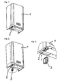
- the heater 1 is mounted on the wall.
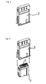
- the cables for connecting the controller and the power supply are located below the heater 1. These cables are screwed into the luster terminals 5 of the insert 4 at appropriate locations. Now the insert 4 is inserted into the plug 3 and engages by means of latching connections, so that insert 4 and plug 3 form a unit.
- the provided with the connecting cables plug 3 is now inserted into the slot 2 at the bottom of the heater 1, whereby the heater 1 is connected to both the power supply and to the external controller.
- the slot can also be mounted laterally or above.
- a sender / receiver (e.g., Bluetooth, 466 MHz, or other) may also be connected to a slot.
Landscapes
- Engineering & Computer Science (AREA)
- Physics & Mathematics (AREA)
- Thermal Sciences (AREA)
- Chemical & Material Sciences (AREA)
- Combustion & Propulsion (AREA)
- Mechanical Engineering (AREA)
- General Engineering & Computer Science (AREA)
- Resistance Heating (AREA)
- Cookers (AREA)
- Control Of Resistance Heating (AREA)
- Central Heating Systems (AREA)
- Baking, Grill, Roasting (AREA)
Description
- Heizgeräte gemäß dem Stand der Technik verfügen über einen Netzanschluss sowie häufig über Leitungen, die zu einem Temperatursensor oder einer externen Regelung führen. Zum Anschluss dieser Leitungen wird in der Regel der Gehäusedeckel entfernt, der Reglerkasten aufgeschraubt, und die Leitungen werden mit Lüsterklemmen festgeschraubt.
- Die Druckschrift
DE 297 13 416 U1 zeigt ein wandmontiertes Heizgerät mit einer Ausnehmung mit Deckel an der Frontseite. Zur Montage wird der Deckel aufgeklappt, der Netzanschluss abisoliert und mit der Lüsterklemme in der Ausnehmung verbunden. Gleiches gilt für einen optionalen Raumthermostaten. Da wandhängende Heizgeräte häufig an schlecht zugänglichen Stellen montiert werden, stellt diese Art des Anschließens der elektrischen Leitungen eine aufwändige Arbeit dar. - Die Druckschrift
EP 1 275 910 A2 zeigt ein Heizgerät zur Wandmontage. Das Gerät verfügt über eine Anschlusseinheit mit Steckerbuchse sowie eine Boilereinheit mit Steckerelement auf der Rückseite. Zur Montage wird die Boilereinheit horizontal in die Anschlusseinheit geschoben, so dass das Steckerelement in die Steckerbuchse einrastet. Zur Montage weiterer elektrischen Verbindungen die Boilereinheit aus der Anschlusseinheit herausgezogen werden; anschließend kann die Anschlusseinheit von der Wand demontiert werden, um die Anschlüsse mit der Wandseite der Steckerbuchse zu verbinden. - Der Erfindung liegt die Aufgabe zugrunde, eine einfache Montage der elektrischen Anschlüsse zu ermöglichen.
- Erfindungsgemäß wird dies durch die Merkmale des unabhängigen Anspruchs 1 erreicht.
- Gemäß den Merkmalen der abhängigen Ansprüche kann der Stecker über einen Einsatz verfügen. In diesem Einsatz sind die Anschlussleitungen befestigt. In einer vorteilhaften Ausgestaltung wird der Einsatz in den Stecker eingeschoben mit mittels Rastverbindung oder Schraubverbindung mit dem Steckergehäuse zu einer Einheit verbunden.
- Die Erfindung wird nun anhand der Figuren detailliert erläutert.
-
Figur 1 zeigt eine Heizgerät 1 mit einem Steckplatz 2 an der Unterseite des Heizgerätes 1, -
Figur 2 zeigt dasselbe Heizgerät 1 mit dem Steckplatz 2, vor dem sich der Stecker 3 befindet, -
Figur 3 zeigt das Detail Stecker vor Steckplatz vergrößert, -
Figur 4 zeigt den Stecker isoliert, -
Figur 5 zeigt den Stecker 3 mit dem Einsatz 4 sowie Lüsterklemmen 5 zum Befestigen der Leitungen. Wie aus den Pfeilen hervorgeht, kann der Einsatz 4 in das Gehäuse des Steckers 3 eingeführt werden. - Das erfindungsgemäße Heizgerät 1 wird an der Wand montiert. Die Kabel zum Anschluss des Reglers und der Spannungsversorgung befinden sich unterhalb des Heizgerätes 1. Diese Leitungen werden in die Lüsterklemmen 5 des Einsatzes 4 an entsprechenden Stellen eingeschraubt. Nun wird der Einsatz 4 in den Stecker 3 eingeschoben und rastet mittels Rastverbindungen ein, so dass Einsatz 4 und Stecker 3 eine Einheit bilden. Der mit den Anschlusskabeln versehene Stecker 3 wird nun in den Steckplatz 2 an der Unterseite des Heizgerätes 1 eingeschoben, wodurch das Heizgerät 1 sowohl mit der Spannungsversorgung als auch mit dem externen Regler verbunden ist.
- Erfindungsgemäß sind auch weitere Varianten denkbar. So kann der Steckplatz auch seitlich oder oben angebracht sein.
- Es ist auch denkbar, dass an einem Heizgerät mehrere Steckplätze parallel angeordnet sind, so dass der Installateur sich den am besten erreichbaren Steckplatz aussuchen kann. Die nicht benötigten Steckplätze können optional abgedeckt werden, so dass sie vor Schmutz und Feuchtigkeit geschützt sind. Sind mehrere Steckplätze vorhanden, so kann optional an einem Steckplatz die Spannungsversorgung erfolgen, während an einem anderen Steckplatz der externe Regler angeschlossen wird. An einem Steckplatz kann auch ein Sender / Empfänger (z.B. Bluetooth, 466 MHz, oder anderes) angeschlossen werden.
Claims (3)
- Heizgerät (1) für die Wandmontage mit elektrischen Anschlüssen und ein Stecker (3), dadurch gekennzeichnet, dass das Heizgerät (1) an mindestens einer anderen Seite als der Montageseite über mindestens einen Steckplatz (2) verfügt, der zur Aufnahme des Steckers (3), welcher Anschlussleitungen für Netzanschluss und Regler enthält, dient.
- Heizgerät (1) nach Anspruch 1, dadurch gekennzeichnet, dass der Stecker (3) über einen Einsatz (4), in welchem die Anschlussleitungen befestigt werden können, verfügt.
- Heizgerät (1) nach Anspruch 2, dadurch gekennzeichnet, dass der Einsatz (4) in den Stecker (3) einschiebbar ist und vorzugsweise mittels Rastverbindung oder Schraubverbindung verbunden wird.
Applications Claiming Priority (1)
| Application Number | Priority Date | Filing Date | Title |
|---|---|---|---|
| AT0007706A AT503217B1 (de) | 2006-01-19 | 2006-01-19 | Heizgerät mit elektrischen anschlüssen |
Publications (2)
| Publication Number | Publication Date |
|---|---|
| EP1811244A1 EP1811244A1 (de) | 2007-07-25 |
| EP1811244B1 true EP1811244B1 (de) | 2015-07-01 |
Family
ID=37907467
Family Applications (1)
| Application Number | Title | Priority Date | Filing Date |
|---|---|---|---|
| EP07000644.0A Active EP1811244B1 (de) | 2006-01-19 | 2007-01-13 | Heizgerät mit elektrischen Anschlüssen |
Country Status (3)
| Country | Link |
|---|---|
| EP (1) | EP1811244B1 (de) |
| AT (1) | AT503217B1 (de) |
| DE (1) | DE102007002050A1 (de) |
Families Citing this family (7)
| Publication number | Priority date | Publication date | Assignee | Title |
|---|---|---|---|---|
| CN104279764B (zh) * | 2014-10-29 | 2017-02-15 | 奥特朗电器(广州)有限公司 | 多功能一体电热水器防电墙 |
| CN105627572B (zh) * | 2014-11-28 | 2022-07-19 | 青岛经济技术开发区海尔热水器有限公司 | 电热水器及其组装方法 |
| US11402127B2 (en) | 2015-12-14 | 2022-08-02 | Think Tank Water Heaters Ltd. | Electric hot water heater energy management |
| CN106403299A (zh) * | 2016-06-17 | 2017-02-15 | 广东万家乐燃气具有限公司 | 一种可自由匹配控制系统的电热水器 |
| DE202017006745U1 (de) * | 2017-11-30 | 2018-04-16 | Robert Bosch Gmbh | Haltevorrichtung für eine Heizvorrichtung, sowie Heizvorrichtung mit einer solchen Haltevorrichtung |
| DE102017222670A1 (de) * | 2017-12-13 | 2019-06-13 | Robert Bosch Gmbh | Heizvorrichtung mit einer Haltevorrichtung zur Aufnahme einer Steuereinheit |
| DE102019202997A1 (de) * | 2019-03-06 | 2020-09-10 | Robert Bosch Gmbh | System mit zumindest einer Brenn- und/oder Heizanlagenvorrichtung |
Family Cites Families (5)
| Publication number | Priority date | Publication date | Assignee | Title |
|---|---|---|---|---|
| DE3505847A1 (de) * | 1985-02-20 | 1986-08-21 | Contact Gmbh Elektrische Bauelemente, 7000 Stuttgart | Vielpoliger, steckbarer klemmenadapter fuer schalt- oder steuerschraenke |
| FR2685823B1 (fr) * | 1991-12-30 | 1995-07-07 | Telemecanique Sa | Bornier pour appareil d'automatisation. |
| IT1292191B1 (it) * | 1996-07-29 | 1999-01-25 | Vaillant Gmbh | Dispositivo di avviamento o di service |
| DE10030131A1 (de) * | 1999-06-25 | 2000-12-28 | Vaillant Joh Gmbh & Co | Anordnung zur Halterung eines Gehäuses |
| GB0116989D0 (en) * | 2001-07-12 | 2001-09-05 | Chamberlain Luke | Boiler unit |
-
2006
- 2006-01-19 AT AT0007706A patent/AT503217B1/de not_active IP Right Cessation
-
2007
- 2007-01-13 DE DE102007002050A patent/DE102007002050A1/de not_active Withdrawn
- 2007-01-13 EP EP07000644.0A patent/EP1811244B1/de active Active
Also Published As
| Publication number | Publication date |
|---|---|
| EP1811244A1 (de) | 2007-07-25 |
| AT503217B1 (de) | 2007-11-15 |
| AT503217A1 (de) | 2007-08-15 |
| DE102007002050A1 (de) | 2007-07-26 |
Similar Documents
| Publication | Publication Date | Title |
|---|---|---|
| EP1811244B1 (de) | Heizgerät mit elektrischen Anschlüssen | |
| EP2523273B1 (de) | Unterputz-Steckdose | |
| DE102013017204A1 (de) | Nachrüstset und Nachrüstverfahren zur Heizungssteuerung | |
| EP2006986A1 (de) | Wechselrichter, umfassend ein Gehäuse | |
| WO2013029732A1 (de) | Unterputz-steckdose | |
| US9872412B2 (en) | Rail-mounted control system | |
| DE202013100297U1 (de) | Geräteanschlusssystem für Küchengeräte | |
| CN103872631B (zh) | 一种快速布线系统 | |
| EP2264845A3 (de) | Elektrische Hausinstallationsverteilung mit einem einen Stromzähler aufweisenden Zählerplatz | |
| JP2007241633A (ja) | 端子変換ユニット | |
| DE202015008263U1 (de) | Stromtechnisch vernetzbare lnfrarotheizungen zur Wandmontage | |
| AT514433B1 (de) | Elektro-Durchlauferhitzer in Modulbauweise | |
| US10447021B1 (en) | Switch boxes and outlet boxes with no wire nuts | |
| AT409434B (de) | Installationskasten | |
| DE3200217A1 (de) | Einrichtung zum erzeugen von warmluftstroemungen | |
| WO1990007207A1 (en) | A multiple purpose electrical extension cable | |
| LU85020A1 (de) | Steuer-und regelungsgeraet fuer heizungsanlagen | |
| EP3319179A1 (de) | Verfahren zum elektrischen anschliessen von elektrischen geräten in einer küche | |
| CN204577683U (zh) | 一种分配器的卡线结构 | |
| DE10252900A1 (de) | Steckverbindung für Wand- und Deckenelektroanschlüsse, z. B. Decken- und Wandlampen | |
| DE202013009704U1 (de) | Elektrisches Haustechnikgerät | |
| DE20301240U1 (de) | Überspannungsschutzgerät | |
| DE202018101419U1 (de) | Heizvorrichtung mit einer Halterung | |
| DE102010048756A1 (de) | Mehrfachladestation und damit ausgerüstetes Prüfsystem | |
| DE4202328A1 (de) | Warmwasserbereiter |
Legal Events
| Date | Code | Title | Description |
|---|---|---|---|
| PUAI | Public reference made under article 153(3) epc to a published international application that has entered the european phase |
Free format text: ORIGINAL CODE: 0009012 |
|
| AK | Designated contracting states |
Kind code of ref document: A1 Designated state(s): AT BE BG CH CY CZ DE DK EE ES FI FR GB GR HU IE IS IT LI LT LU LV MC NL PL PT RO SE SI SK TR |
|
| AX | Request for extension of the european patent |
Extension state: AL BA HR MK YU |
|
| 17P | Request for examination filed |
Effective date: 20071213 |
|
| AKX | Designation fees paid |
Designated state(s): AT BE BG CH CY CZ DE DK EE ES FI FR GB GR HU IE IS IT LI LT LU LV MC NL PL PT RO SE SI SK TR |
|
| GRAP | Despatch of communication of intention to grant a patent |
Free format text: ORIGINAL CODE: EPIDOSNIGR1 |
|
| GRAS | Grant fee paid |
Free format text: ORIGINAL CODE: EPIDOSNIGR3 |
|
| INTG | Intention to grant announced |
Effective date: 20150430 |
|
| GRAA | (expected) grant |
Free format text: ORIGINAL CODE: 0009210 |
|
| AK | Designated contracting states |
Kind code of ref document: B1 Designated state(s): AT BE BG CH CY CZ DE DK EE ES FI FR GB GR HU IE IS IT LI LT LU LV MC NL PL PT RO SE SI SK TR |
|
| REG | Reference to a national code |
Ref country code: GB Ref legal event code: FG4D Free format text: NOT ENGLISH |
|
| REG | Reference to a national code |
Ref country code: AT Ref legal event code: REF Ref document number: 734201 Country of ref document: AT Kind code of ref document: T Effective date: 20150715 Ref country code: CH Ref legal event code: EP |
|
| REG | Reference to a national code |
Ref country code: DE Ref legal event code: R096 Ref document number: 502007014008 Country of ref document: DE |
|
| REG | Reference to a national code |
Ref country code: IE Ref legal event code: FG4D Free format text: LANGUAGE OF EP DOCUMENT: GERMAN |
|
| REG | Reference to a national code |
Ref country code: NL Ref legal event code: MP Effective date: 20150701 |
|
| REG | Reference to a national code |
Ref country code: LT Ref legal event code: MG4D |
|
| PG25 | Lapsed in a contracting state [announced via postgrant information from national office to epo] |
Ref country code: LV Free format text: LAPSE BECAUSE OF FAILURE TO SUBMIT A TRANSLATION OF THE DESCRIPTION OR TO PAY THE FEE WITHIN THE PRESCRIBED TIME-LIMIT Effective date: 20150701 Ref country code: LT Free format text: LAPSE BECAUSE OF FAILURE TO SUBMIT A TRANSLATION OF THE DESCRIPTION OR TO PAY THE FEE WITHIN THE PRESCRIBED TIME-LIMIT Effective date: 20150701 Ref country code: FI Free format text: LAPSE BECAUSE OF FAILURE TO SUBMIT A TRANSLATION OF THE DESCRIPTION OR TO PAY THE FEE WITHIN THE PRESCRIBED TIME-LIMIT Effective date: 20150701 Ref country code: GR Free format text: LAPSE BECAUSE OF FAILURE TO SUBMIT A TRANSLATION OF THE DESCRIPTION OR TO PAY THE FEE WITHIN THE PRESCRIBED TIME-LIMIT Effective date: 20151002 |
|
| PG25 | Lapsed in a contracting state [announced via postgrant information from national office to epo] |
Ref country code: PL Free format text: LAPSE BECAUSE OF FAILURE TO SUBMIT A TRANSLATION OF THE DESCRIPTION OR TO PAY THE FEE WITHIN THE PRESCRIBED TIME-LIMIT Effective date: 20150701 Ref country code: SE Free format text: LAPSE BECAUSE OF FAILURE TO SUBMIT A TRANSLATION OF THE DESCRIPTION OR TO PAY THE FEE WITHIN THE PRESCRIBED TIME-LIMIT Effective date: 20150701 Ref country code: IS Free format text: LAPSE BECAUSE OF FAILURE TO SUBMIT A TRANSLATION OF THE DESCRIPTION OR TO PAY THE FEE WITHIN THE PRESCRIBED TIME-LIMIT Effective date: 20151101 Ref country code: ES Free format text: LAPSE BECAUSE OF FAILURE TO SUBMIT A TRANSLATION OF THE DESCRIPTION OR TO PAY THE FEE WITHIN THE PRESCRIBED TIME-LIMIT Effective date: 20150701 |
|
| REG | Reference to a national code |
Ref country code: DE Ref legal event code: R097 Ref document number: 502007014008 Country of ref document: DE |
|
| PG25 | Lapsed in a contracting state [announced via postgrant information from national office to epo] |
Ref country code: CZ Free format text: LAPSE BECAUSE OF FAILURE TO SUBMIT A TRANSLATION OF THE DESCRIPTION OR TO PAY THE FEE WITHIN THE PRESCRIBED TIME-LIMIT Effective date: 20150701 Ref country code: EE Free format text: LAPSE BECAUSE OF FAILURE TO SUBMIT A TRANSLATION OF THE DESCRIPTION OR TO PAY THE FEE WITHIN THE PRESCRIBED TIME-LIMIT Effective date: 20150701 Ref country code: SK Free format text: LAPSE BECAUSE OF FAILURE TO SUBMIT A TRANSLATION OF THE DESCRIPTION OR TO PAY THE FEE WITHIN THE PRESCRIBED TIME-LIMIT Effective date: 20150701 Ref country code: IT Free format text: LAPSE BECAUSE OF FAILURE TO SUBMIT A TRANSLATION OF THE DESCRIPTION OR TO PAY THE FEE WITHIN THE PRESCRIBED TIME-LIMIT Effective date: 20150701 Ref country code: DK Free format text: LAPSE BECAUSE OF FAILURE TO SUBMIT A TRANSLATION OF THE DESCRIPTION OR TO PAY THE FEE WITHIN THE PRESCRIBED TIME-LIMIT Effective date: 20150701 |
|
| PLBE | No opposition filed within time limit |
Free format text: ORIGINAL CODE: 0009261 |
|
| STAA | Information on the status of an ep patent application or granted ep patent |
Free format text: STATUS: NO OPPOSITION FILED WITHIN TIME LIMIT |
|
| PG25 | Lapsed in a contracting state [announced via postgrant information from national office to epo] |
Ref country code: RO Free format text: LAPSE BECAUSE OF FAILURE TO SUBMIT A TRANSLATION OF THE DESCRIPTION OR TO PAY THE FEE WITHIN THE PRESCRIBED TIME-LIMIT Effective date: 20150701 Ref country code: BE Free format text: LAPSE BECAUSE OF NON-PAYMENT OF DUE FEES Effective date: 20160131 |
|
| 26N | No opposition filed |
Effective date: 20160404 |
|
| PG25 | Lapsed in a contracting state [announced via postgrant information from national office to epo] |
Ref country code: SI Free format text: LAPSE BECAUSE OF FAILURE TO SUBMIT A TRANSLATION OF THE DESCRIPTION OR TO PAY THE FEE WITHIN THE PRESCRIBED TIME-LIMIT Effective date: 20150701 Ref country code: LU Free format text: LAPSE BECAUSE OF FAILURE TO SUBMIT A TRANSLATION OF THE DESCRIPTION OR TO PAY THE FEE WITHIN THE PRESCRIBED TIME-LIMIT Effective date: 20160113 |
|
| REG | Reference to a national code |
Ref country code: CH Ref legal event code: PL |
|
| PG25 | Lapsed in a contracting state [announced via postgrant information from national office to epo] |
Ref country code: MC Free format text: LAPSE BECAUSE OF FAILURE TO SUBMIT A TRANSLATION OF THE DESCRIPTION OR TO PAY THE FEE WITHIN THE PRESCRIBED TIME-LIMIT Effective date: 20150701 |
|
| REG | Reference to a national code |
Ref country code: FR Ref legal event code: ST Effective date: 20160930 |
|
| PG25 | Lapsed in a contracting state [announced via postgrant information from national office to epo] |
Ref country code: LI Free format text: LAPSE BECAUSE OF NON-PAYMENT OF DUE FEES Effective date: 20160131 Ref country code: CH Free format text: LAPSE BECAUSE OF NON-PAYMENT OF DUE FEES Effective date: 20160131 |
|
| REG | Reference to a national code |
Ref country code: IE Ref legal event code: MM4A |
|
| PG25 | Lapsed in a contracting state [announced via postgrant information from national office to epo] |
Ref country code: FR Free format text: LAPSE BECAUSE OF NON-PAYMENT OF DUE FEES Effective date: 20160201 |
|
| PG25 | Lapsed in a contracting state [announced via postgrant information from national office to epo] |
Ref country code: IE Free format text: LAPSE BECAUSE OF NON-PAYMENT OF DUE FEES Effective date: 20160113 |
|
| REG | Reference to a national code |
Ref country code: AT Ref legal event code: MM01 Ref document number: 734201 Country of ref document: AT Kind code of ref document: T Effective date: 20160113 |
|
| PG25 | Lapsed in a contracting state [announced via postgrant information from national office to epo] |
Ref country code: AT Free format text: LAPSE BECAUSE OF NON-PAYMENT OF DUE FEES Effective date: 20160113 |
|
| PG25 | Lapsed in a contracting state [announced via postgrant information from national office to epo] |
Ref country code: NL Free format text: LAPSE BECAUSE OF FAILURE TO SUBMIT A TRANSLATION OF THE DESCRIPTION OR TO PAY THE FEE WITHIN THE PRESCRIBED TIME-LIMIT Effective date: 20150701 |
|
| PG25 | Lapsed in a contracting state [announced via postgrant information from national office to epo] |
Ref country code: CY Free format text: LAPSE BECAUSE OF FAILURE TO SUBMIT A TRANSLATION OF THE DESCRIPTION OR TO PAY THE FEE WITHIN THE PRESCRIBED TIME-LIMIT Effective date: 20150701 Ref country code: HU Free format text: LAPSE BECAUSE OF FAILURE TO SUBMIT A TRANSLATION OF THE DESCRIPTION OR TO PAY THE FEE WITHIN THE PRESCRIBED TIME-LIMIT; INVALID AB INITIO Effective date: 20070113 |
|
| PG25 | Lapsed in a contracting state [announced via postgrant information from national office to epo] |
Ref country code: PT Free format text: LAPSE BECAUSE OF FAILURE TO SUBMIT A TRANSLATION OF THE DESCRIPTION OR TO PAY THE FEE WITHIN THE PRESCRIBED TIME-LIMIT Effective date: 20150701 Ref country code: TR Free format text: LAPSE BECAUSE OF FAILURE TO SUBMIT A TRANSLATION OF THE DESCRIPTION OR TO PAY THE FEE WITHIN THE PRESCRIBED TIME-LIMIT Effective date: 20150701 |
|
| PG25 | Lapsed in a contracting state [announced via postgrant information from national office to epo] |
Ref country code: BG Free format text: LAPSE BECAUSE OF FAILURE TO SUBMIT A TRANSLATION OF THE DESCRIPTION OR TO PAY THE FEE WITHIN THE PRESCRIBED TIME-LIMIT Effective date: 20150701 |
|
| P01 | Opt-out of the competence of the unified patent court (upc) registered |
Effective date: 20230528 |
|
| PGFP | Annual fee paid to national office [announced via postgrant information from national office to epo] |
Ref country code: GB Payment date: 20231219 Year of fee payment: 18 |
|
| PGFP | Annual fee paid to national office [announced via postgrant information from national office to epo] |
Ref country code: DE Payment date: 20231219 Year of fee payment: 18 |