EP1810826A2 - Sheet fed printing press - Google Patents
Sheet fed printing press Download PDFInfo
- Publication number
- EP1810826A2 EP1810826A2 EP07000754A EP07000754A EP1810826A2 EP 1810826 A2 EP1810826 A2 EP 1810826A2 EP 07000754 A EP07000754 A EP 07000754A EP 07000754 A EP07000754 A EP 07000754A EP 1810826 A2 EP1810826 A2 EP 1810826A2
- Authority
- EP
- European Patent Office
- Prior art keywords
- sheet
- printing
- fed
- formless
- printing device
- Prior art date
- Legal status (The legal status is an assumption and is not a legal conclusion. Google has not performed a legal analysis and makes no representation as to the accuracy of the status listed.)
- Withdrawn
Links
Images


Classifications
-
- B—PERFORMING OPERATIONS; TRANSPORTING
- B41—PRINTING; LINING MACHINES; TYPEWRITERS; STAMPS
- B41J—TYPEWRITERS; SELECTIVE PRINTING MECHANISMS, i.e. MECHANISMS PRINTING OTHERWISE THAN FROM A FORME; CORRECTION OF TYPOGRAPHICAL ERRORS
- B41J3/00—Typewriters or selective printing or marking mechanisms characterised by the purpose for which they are constructed
- B41J3/54—Typewriters or selective printing or marking mechanisms characterised by the purpose for which they are constructed with two or more sets of type or printing elements
- B41J3/546—Combination of different types, e.g. using a thermal transfer head and an inkjet print head
-
- B—PERFORMING OPERATIONS; TRANSPORTING
- B41—PRINTING; LINING MACHINES; TYPEWRITERS; STAMPS
- B41F—PRINTING MACHINES OR PRESSES
- B41F19/00—Apparatus or machines for carrying out printing operations combined with other operations
- B41F19/007—Apparatus or machines for carrying out printing operations combined with other operations with selective printing mechanisms, e.g. ink-jet or thermal printers
Definitions
- the invention relates to a sheet-fed printing machine according to the preamble of claim 1.
- pressure-free printing devices are increasingly used, which are preferably used for the individualization of printed products produced by offset printing with, for example, barcodes, numbering or other markings.
- Such printing formless printing devices are also referred to as non-impact print (NIP) printing devices and can be embodied, for example, as inkjet printing devices which have at least one inkjet print head, wherein the or each inkjet print head according to the so-called continuous inkjet principle, The drop-on-demand inkjet principle, the thermal inkjet principle or any other inkjet principle can work.
- the pressure-formless or NIP printing devices can also be designed as laser printing devices.
- a sheet-fed printing machine in which a designed as an inkjet printing device or as a laser printing device, pressure-free printing device is integrated in an offset printing unit of the sheet-fed press.
- the pressure-formless printing device with respect to a sheet-guiding impression cylinder in the area after the passage of sheet is arranged by a pressure gap formed by the impression cylinder and a blanket cylinder.
- the printing machine according to DE 197 04 003 A1 In particular, the printing of printed sheets with a high rigidity in the area of the inkjet printing device or laser printing device is problematic.
- Another sheet-fed press with a built-in pressure-free printing device is from the DE 195 14 259 A1 known, the pressure-formless printing device seen in the transport direction of the sheet seen behind the last offset printing unit and in the transport direction of the sheet seen in front of a boom of the sheet-fed press integrated into this according to this prior art.
- the present invention is based on the problem to provide a novel sheet-fed printing machine.
- the or each pressure-formless printing device is integrated in the sheet-fed printing machine in the area of the feeder.
- the or each pressure-formless printing device in the area of the feeder of the sheet-fed printing machine into the same. Accordingly, in the context of the present invention, the printing of printed sheets with the help of or any pressure-free printing device at a time, which is prior to printing the sheet in the preferably formed as offset printing units of the sheet-fed printing press.
- the printing formless printing devices can be arranged with a small distance to the printed sheet, without rolling on the sheet to be printed on the sheet Sheet guide rollers are required, which on the one hand affect the print quality and on the other hand limit the printable in the range of or any pressure-free device width of the sheet.
- Fig. 1 shows a schematic representation of a sheet-fed printing machine 10, wherein the sheet-fed printing machine 10 comprises a feeder 11, a plurality formed as offset printing units printing units 12, a printing units 12 downstream coating unit 13 and the coating unit 13 downstream boom 14.
- the feeder 11 is used for feeding sheet to be printed in the sheet-fed press 10, wherein the sheets are moved through the printing units 12 and the coating unit 13 and printed in the same with a print sheet for all the same or unchanging and thus static printed image.
- printed signatures are discharged from the sheet-fed printing press to form a delivery stack 15.
- the sheet-fed printing machine 10 is designed as a so-called turning machine, which serves the two-sided printing of printed sheets in the so-called perfecting.
- a arranged between the first two printing units 12 transfer cylinder is this formed as a turning cylinder 16.
- At least one pressure-formless printing device is integrated, which preferably serves to print the printed sheet with a dynamic or variable print image.
- the or each pressure-formless printing device is integrated in the area of the feeder 11 in the sheet-fed press 10, wherein in Fig. 1 possible mounting positions 17 and 18 are shown schematically for the or each pressure-formless printing device. In both installation positions 17 and 18, the printed sheets are printed in the region of the feeder 11 via the or each pressure-formless printing device from above.
- the installation position 18 is preferred for each pressure-formless printing device, namely above an investment table 19, via which printed sheets lifted from an feeder stack 20 are fed to the first printing unit 12 of the printing press.
- the printed sheets are guided on their underside by at least one suction belt, so that the printing sheets of the or each printing forme printing device on an upper side thereof are printable, namely over the entire format width and format length thereof.
- the sheets are flat or flat. It can be maintained a small distance between the or each pressure-free printing device and the sheet and thus a high print quality can be provided.
- a pressure-free printing device is integrated into the feeder 11 in the installed position 18 above an investment table 19, the installation position along the contact table 19 can be freely selected.
- the printing forme printing device then at least a leading edge and a side edge of the sheet must then be detected and evaluated to print the sheets in the desired zones thereof.
- the sensors required to detect the leading edge and side edge may be provided via infrared or ultrasonic sensors or capacitive sensors.
- the installation position 17 is preferred for the or each pressure-formless printing device, namely above a contact plate of the flaker feeder, not shown in FIG. 1, wherein the printed sheets are separated in the region of the contact plate and detected by a so-called pre-gripper 21 and the first printing unit 12 of the sheet-fed printing machine 10 are supplied.
- the printed sheets of the or each printing formless printing device over the entire format width and format length can be printed with a dynamic or variable printed image.
- a printing formless printing device is integrated in the installation position 17 adjacent to the pre-gripper 21 in the feeder 11, at least one leading edge of the printed sheet must be detected and evaluated in order to control the printing form free printing device in the desired zones thereof to print.
- the required for detecting the leading edge sensor can be provided in turn via infrared or ultrasonic sensors or capacitive sensors.
- a sheet guiding device is preferably positioned which can be displaced into regions or zones of the printed sheets which are not to be printed by the printing-formless printing device.
- At least one characteristic curve is stored in a control device of the printing-form-free printing device which depends on substrate characteristics such as the grammage and / or the grain direction and / or the stiffness of the sheet Printed sheet is.
- the pressure-formless printing device is then controlled based on one of these characteristics.
- the characteristic curves are determined in advance for printed sheets from different substrates.
- the or each in the sheet-fed printing machine 10 integrated pressure-free printing device is preferably designed as an inkjet printing device or laser printing device, said printing devices seen transversely to the transport direction of the sheet seen a plurality of juxtaposed inkjet printheads or laser printheads and seen in the transport direction of the sheet a plurality of successively arranged
- inkjet printheads or laser printheads arranged array-like or matrix-like to each other and preferably interconnected on the control side.
- the number of print heads required transversely to the printing direction is primarily defined by the desired total print width relative to the given print width of the print head used.
- the required number of printheads in the transport direction of the sheet is, however, determined by the fact that the desired printing speed is greater than the given printing speed of a printhead and in that a plurality of inks are to be applied to the sheets by means of pressure-free printing device. Furthermore, the number of print heads in the transport direction of the print sheets is defined by the desired print resolution in relation to the given print resolution of the print head used.
- the printing units 12 and the coating unit 13 of the sheet-fed printing press 10 serve to print the printed sheets with a static, identical for all printed image.
- the or each in the area of the investor 11 integrated in the sheet-fed press 10 formless device is used to print the sheet with a dynamic or variable print image, the printing with the dynamic or variable print image inline for printing the sheet with the static image, namely, in time before printing the sheet in the printing units 12 and the coating unit 13th
- Fig. 2 shows the application of the invention in a sheet-fed press 22, in the transport direction of the sheet seen after the feeder 11 designed as a flexo printing unit printing unit 23 and seen in the transport direction of the sheet before the boom 14, a coating unit 24 is arranged, and wherein between the flexographic printing unit 23 and the coating unit 24 two drying devices 25 are positioned.
- At least one pressure-formless printing device in the region of the feeder 11 is integrated into the sheet-fed printing press 22, namely either in the area of the installation position 17 or in the area of the installation position 18, so that reference may be made to the embodiments of the embodiment of FIG ,
- the installation position 17 is preferred in the case of a feeder designed as a flaker feeder and the installation position 18 in the case of a feeder designed as a single-sheet feeder.
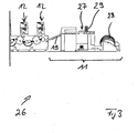
- Fig. 3 shows a section of a further sheet-fed printing machine 26 according to the invention, in which the feeder 11 is designed as a roll-sheet feeder, and wherein the roll sheet feeder 11 seen in the transport direction of the sheet seen downstream of two printing units 12 designed as offset printing units are.
- the roll-bow feeder 11 comprises a sheet-roll cutter 27, also referred to as an inline sheeter. In the area of the sheet-roll cutter 27, printed sheets are cut from a roll-shaped printing material 28, which are then fed via a feed table 19 to the first printing unit 12 of the sheet-fed printing machine 26.
- the or each pressure-formless printing device is preferably integrated into the feeder 11 of the sheet-fed printing press 26 according to the invention at the installation position 29 schematically illustrated in FIG.
- the printed sheets can be printed over the entire format width and format length from above with a variable or variable print image.
- the or each pressure-formless printing device of the sheet-fed printing machine can be disassembled, in such a way that the or each pressure-formless printing device can be used on a different sheet-fed press or within the same sheet-fed press at different mounting positions.
- the or each pressure-formless printing device has a supply side, namely mechanical or printing ink side, and a control side, namely electrical or electronic, interface, via which the or any pressure-free printing device can be connected to an ink supply system or to a control device of the respective printing press ,
- pressure-free printing devices are integrated into a sheet-fed printing machine at several installation positions, then the electrical and mechanical interfaces for these printing devices can be centralized.
- To the or each pressure-formless printing device leading supply lines be it electrical supply lines or mechanical or pressure-color side supply lines can either be permanently installed on the sheet-fed press according to the invention or be brought to the sheet-fed press mobile. Due to the dismantling of the or each printing formless printing device of the sheet-fed printing machine according to the invention maintenance and cleaning of the printing formless printing devices outside the range of the sheet-fed press can be performed.
- the printing formless printing device is preferably arranged downstream of a drying device or curing device and / or a suction device, wherein the drying device serves to dry the printing ink applied via the printing formless printing device and the suction device to remove solvent vapors from the ink applied via the printing plate free printing device.
- the pressure-formless printing device is arranged pivotably in the region of the feeder 11, preferably on a feeder arm, which engages on a side frame of the feeder or the first printing unit. As a result, the feeder 11 is freely accessible for setup work.
Abstract
Description
Die Erfindung betrifft eine Bogendruckmaschine gemäß dem Oberbegriff des Anspruchs 1.The invention relates to a sheet-fed printing machine according to the preamble of claim 1.
In nach dem Offset-Druckprinzip arbeitenden Bogendruckmaschinen finden zunehmend druckformlose Druckeinrichtungen Verwendung, die vorzugsweise der Individualisierung von über den Offsetdruck hergestellten Druckerzeugnissen mit zum Beispiel Barcodes, Nummerierungen oder sonstigen Markierungen dienen. Derartige druckformlose Druckeinrichtungen werden auch als Non Impact Print (NIP) Druckeinrichtungen bezeichnet und können zum Beispiel als Inkjet-Druckeinrichtungen ausgeführt sein, die über mindestens einen Inkjet-Druckkopf verfügen, wobei der oder jeder Inkjet-Druckkopf nach dem sogenannten Continuous-Inkjet-Prinzip, dem Drop-On-Demand-Inkjet-Prinzip, dem Thermal-Inkjet-Prinzip oder jedem anderem Inkjet-Prinzip arbeiten kann. Die druckformlosen bzw. NIP Druckeinrichtungen können auch als Laser-Druckeinrichtungen ausgeführt sein.In sheet-fed printing presses working according to the offset printing principle, pressure-free printing devices are increasingly used, which are preferably used for the individualization of printed products produced by offset printing with, for example, barcodes, numbering or other markings. Such printing formless printing devices are also referred to as non-impact print (NIP) printing devices and can be embodied, for example, as inkjet printing devices which have at least one inkjet print head, wherein the or each inkjet print head according to the so-called continuous inkjet principle, The drop-on-demand inkjet principle, the thermal inkjet principle or any other inkjet principle can work. The pressure-formless or NIP printing devices can also be designed as laser printing devices.
Aus der
Dies liegt darin begründet, dass solche Druckbogen im Bereich der Bogenhinterkante nach dem Verlassen des Druckspalts zum Hochschnellen neigen und sich so der Abstand zwischen der druckformlosen Druckeinrichtung und dem Druckbogen schlagartig verändern kann, weshalb die Druckbogen ohne entsprechende Führungselemente gegen die druckformlose Druckeinrichtung schlagen können und somit die Druckbogen im Bereich der Bogenhinterkante nicht mit dergleichen Qualität wie im Bereich einer Bogenvorderkante und/oder einer Bogenmitte bedruckt werden können.This is due to the fact that such printed sheets in the region of the sheet trailing edge after leaving the printing nip tend to bounce and so can change the distance between the printing formless printing device and the sheet abruptly, which is why the sheet can strike without corresponding guide elements against the pressure-formless printing device and thus the printed sheets in the region of the sheet trailing edge can not be printed with the same quality as in the area of a sheet leading edge and / or a sheet center.
Zur Fixierung der Druckbogen auf der Oberfläche des Gegendruckzylinders werden in der
Eine weitere Bogendruckmaschine mit einer in dieselben integrierten, druckformlosen Druckeinrichtung ist aus der
Hiervon ausgehend liegt der vorliegenden Erfindung das Problem zugrunde, eine neuartige Bogendruckmaschine zu schaffen.On this basis, the present invention is based on the problem to provide a novel sheet-fed printing machine.
Dieses Problem wird durch eine Bogendruckmaschine gemäß Anspruch 1 gelöst. Erfindungsgemäß ist die oder jede druckformlose Druckeinrichtung im Bereich des Anlegers in die Bogendruckmaschine integriert.This problem is solved by a sheet-fed printing machine according to claim 1. According to the invention, the or each pressure-formless printing device is integrated in the sheet-fed printing machine in the area of the feeder.
Im Sinne der hier vorliegenden Erfindung wird vorgeschlagen, die oder jede druckformlose Druckeinrichtung im Bereich des Anlegers der Bogendruckmaschine in dieselbe zu integrieren. Demnach erfolgt im Sinne der hier vorliegenden Erfindung das Bedrucken von Druckbogen mit Hilfe der oder jeder druckformlosen Druckeinrichtung zu einem Zeitpunkt, der vor dem Bedrucken der Druckbogen in den vorzugsweise als Offset-Druckwerken ausgebildeten Druckwerken der Bogendruckmaschine liegt. Da die zu bedruckenden Druckbogen im Bereich des Anlegers eben und nicht wie im Bereich der Druckwerke der Bogendruckmaschine gekrümmt verlaufen bzw. ausgerichtet sind, können die druckformlosen Druckeinrichtungen mit einem geringen Abstand zu den Druckbogen angeordnet werden, ohne dass auf der zu bedruckenden Seite der Druckbogen abrollende Bogenführungsrollen erforderlich sind, welche einerseits die Druckqualität beeinträchtigen und andererseits die im Bereich der oder jeder druckformlosen Einrichtung bedruckbare Breite der Druckbogen begrenzen.For the purposes of the present invention, it is proposed to integrate the or each pressure-formless printing device in the area of the feeder of the sheet-fed printing machine into the same. Accordingly, in the context of the present invention, the printing of printed sheets with the help of or any pressure-free printing device at a time, which is prior to printing the sheet in the preferably formed as offset printing units of the sheet-fed printing press. Since the printed sheets to be printed in the area of the investor are flat and not curved as in the area of the printing units of the sheet-fed printing press, the printing formless printing devices can be arranged with a small distance to the printed sheet, without rolling on the sheet to be printed on the sheet Sheet guide rollers are required, which on the one hand affect the print quality and on the other hand limit the printable in the range of or any pressure-free device width of the sheet.
Bevorzugte Weiterbildungen der Erfindung ergeben sich aus den Unteransprüchen und der nachfolgenden Beschreibung. Ausführungsbeispiele der Erfindung werden, ohne hierauf beschränkt zu sein, an Hand der Zeichnung näher erläutert. Dabei zeigt:
- Fig. 1:
- eine erfindungsgemäße Bogendruckmaschine nach einem ersten Ausführungsbeispiel der Erfindung;
- Fig. 2:
- eine erfindungsgemäße Bogendruckmaschine nach einem zweiten Ausführungsbeispiel der Erfindung; und
- Fig. 3:
- einen Ausschnitt aus einer erfindungsgemäßen Bogendruckmaschine nach einem dritten Ausführungsbeispiel der Erfindung.
- Fig. 1:
- a sheet-fed printing machine according to a first embodiment of the invention;
- Fig. 2:
- a sheet-fed printing machine according to a second embodiment of the invention; and
- 3:
- a section of a sheet-fed press according to a third embodiment of the invention.
Nachfolgend wird die hier vorliegende Erfindung unter Bezugnahme auf Fig. 1 bis 3 in größerem Detail beschrieben.Hereinafter, the present invention will be described in more detail with reference to FIGS. 1 to 3.
Fig. 1 zeigt eine schematisierte Darstellung einer erfindungsgemäßen Bogendruckmaschine 10, wobei die Bogendruckmaschine 10 einen Anleger 11, mehrere als Offset-Druckwerke ausgebildete Druckwerke 12, ein den Druckwerken 12 nachgeschaltetes Lackwerk 13 sowie einen dem Lackwerk 13 nachgeschalteten Ausleger 14 umfasst. Der Anleger 11 dient dem Einschleusen zu bedruckender Druckbogen in die Bogendruckmaschine 10, wobei die Druckbogen durch die Druckwerke 12 sowie das Lackwerk 13 bewegt und in denselben mit einem für alle Druckbogen gleichen bzw. unveränderlichem und damit statischen Druckbild bedruckt werden. Im Bereich des Auslegers 14 werden bedruckte Druckbogen aus der Bogendruckmaschine unter Bildung eines Auslegerstapels 15 ausgeschleust. Im gezeigten Ausführungsbeispiel der Fig. 1 ist die erfindungsgemäße Bogendruckmaschine 10 als sogenannte Wendemaschine ausgebildet, die dem beidseitigen Bedrucken von Druckbogen im sogenannten Schön- und Widerdruck dient. Ein zwischen den beiden ersten Druckwerken 12 angeordneter Transferzylinder ist hierzu als Wendezylinder 16 ausgebildet.Fig. 1 shows a schematic representation of a sheet-fed
In die erfindungsgemäße Bogendruckmaschine 10 ist mindestens eine druckformlose Druckeinrichtung integriert, die vorzugsweise dem Bedrucken der Druckbogen mit einem dynamischen bzw. veränderlichen Druckbild dient. Im Sinne der hier vorliegenden Erfindung ist die oder jede druckformlose Druckeinrichtung im Bereich des Anlegers 11 in die Bogendruckmaschine 10 integriert, wobei in Fig. 1 mögliche Einbaupositionen 17 und 18 für die oder jede druckformlose Druckeinrichtung schematisiert dargestellt sind. In beiden Einbaupositionen 17 und 18 werden die Druckbogen im Bereich des Anlegers 11 über die oder jede druckformlose Druckeinrichtung von oben bedruckt.In the sheet-fed
In dem Fall, in welchem der Anleger 11 als sogenannter Einzelbogenanleger ausgebildet ist, ist die Einbauposition 18 für jede druckformlose Druckeinrichtung bevorzugt, nämlich oberhalb eines Anlagetisches 19, über welchen von einem Anlegerstapel 20 abgehobene Druckbogen dem ersten Druckwerk 12 der Druckmaschine zugeführt werden. Im Bereich des Anlagetisches 19 werden die Druckbogen an ihre Unterseite durch mindestens ein Saugband geführt, sodass die Druckbogen von der oder jeder druckformlosen Druckeinrichtung an einer Oberseite derselben bedruckbar sind, nämlich über die gesamte Formatbreite sowie Formatlänge derselben. Beim Transport der Druckbogen entlang des Anlagetisches 19 sind die Druckbogen eben bzw. plan ausgerichtet. Es kann ein geringer Abstand zwischen der oder jeder druckformlosen Druckeinrichtung und dem Druckbogen eingehalten und somit eine hohe Druckqualität bereitgestellt werden.In the case in which the
Ist bei einem als Einzelbogenanleger ausgebildeten Anleger 11 eine druckformlose Druckeinrichtung in der Einbauposition 18 oberhalb eines Anlagetisches 19 in den Anleger 11 integriert, so ist die Einbauposition entlang des Anlagetisches 19 frei wählbar. Zur Steuerung der druckformlosen Druckeinrichtung müssen dann zumindest eine Vorderkante und eine Seitenkante der Druckbogen erfasst und ausgewertet werden, um die Druckbogen in den gewünschten Zonen derselben zu bedrucken. Die zur Erfassung der Vorderkante und Seitenkante erforderliche Sensorik kann über Infrarot- oder Ultraschall-Sensoren oder kapazitive Sensoren bereitgestellt werden.If, in the case of a
In dem Fall, in welchem der Anleger 11 als sogenannter Schuppenanleger ausgebildet ist, ist die Einbauposition 17 für die oder jede druckformlose Druckeinrichtung bevorzugt, nämlich oberhalb eines in Fig. 1 nicht-dargestellten Anlageblechs des Schuppenanlegers, wobei im Bereich des Anlageblechs die Druckbogen vereinzelt und von einem sogenannten Vorgreifer 21 erfasst und dem ersten Druckwerk 12 der Bogendruckmaschine 10 zugeführt werden. Auch in diesem Fall können die Druckbogen von der oder jeder druckformlosen Druckeinrichtung über die gesamte Formatbreite sowie Formatlänge mit einem dynamischen bzw. veränderlichen Druckbild bedruckt werden.In the case in which the
Ist bei einem als Schuppenanleger ausgebildeten Anleger 11 eine druckformlose Druckeinrichtung in der Einbauposition 17 benachbart zum Vorgreifer 21 in den Anleger 11 integriert, so muss zur Steuerung der druckformlosen Druckeinrichtung zumindest eine Vorderkante der Druckbogen erfasst und ausgewertet werden, um die Druckbogen in den gewünschten Zonen derselben zu bedrucken. Die zur Erfassung der Vorderkante erforderliche Sensorik kann wiederum über Infrarot- oder Ultraschall-Sensoren oder kapazitive Sensoren bereitgestellt werden. Zwischen der druckformlosen Druckeinrichtung 17 und dem Vorgreifer 21 ist vorzugsweise eine Bogenführungseinrichtung positioniert, die in von der druckformlosen Druckeinrichtung nicht zu bedruckende Bereiche bzw. Zonen der Druckbogen verschoben werden kann.If, in the case of a
Verändert sich beim Einziehen der Druckbogen in die Bogendruckmaschine über den Vorgreifer 21 die Transportgeschwindigkeit der Druckbogen, so ist vorzugsweise in einer Steuerungseinrichtung der druckformlosen Druckeinrichtung mindestens eine Kennlinie hinterlegt, die abhängig von Bedruckstoffkenngrößen wie der Grammatur und/oder der Faserrichtung und/oder der Steifigkeit der Druckbogen ist. Die druckformlose Druckeinrichtung wird dann auf Basis einer dieser Kennlinien angesteuert. Die Kennlinien werden vorab für Druckbogen aus unterschiedlichen Bedruckstoffen ermittelt.If the transport speed of the printed sheets changes over the pre-gripper 21 when the sheet is fed into the sheet-fed printing press, then at least one characteristic curve is stored in a control device of the printing-form-free printing device which depends on substrate characteristics such as the grammage and / or the grain direction and / or the stiffness of the sheet Printed sheet is. The pressure-formless printing device is then controlled based on one of these characteristics. The characteristic curves are determined in advance for printed sheets from different substrates.
Die oder jede in die Bogendruckmaschine 10 integrierte druckformlose Druckeinrichtung ist vorzugsweise als Inkjet-Druckeinrichtung oder Laser-Druckeinrichtung ausgebildet, wobei solche Druckeinrichtungen quer zur Transportrichtung der Druckbogen gesehen mehrere nebeneinander angeordnete Inkjet-Druckköpfe oder Laser-Druckköpfe sowie in Transportrichtung der Druckbogen gesehen mehrere hintereinander angeordnete Inkjet-Druckköpfe bzw. Laser-Druckköpfe aufweisen, die arrayartig bzw. matrixartig zueinander angeordnet und vorzugsweise untereinander steuerungsseitig verschaltet sind.The or each in the sheet-fed
Die Anzahl der quer zur Druckrichtung benötigten Druckköpfe wird in erster Linie durch die gewünschte Gesamtdruckbreite bezogen auf die gegebene Druckbreite des verwendeten Druckkopfs definiert.The number of print heads required transversely to the printing direction is primarily defined by the desired total print width relative to the given print width of the print head used.
Die benötigte Anzahl an Druckköpfen in Transportrichtung der Druckbogen wird hingegen dadurch bestimmt, dass die gewünschte Druckgeschwindigkeit größer ist als die gegebene Druckgeschwindigkeit eines Druckkopfs sowie dadurch, dass mehrere Druckfarben auf die Druckbogen mit Hilfe der druckformlosen Druckeinrichtung aufgetragen werden sollen. Weiterhin wird die Anzahl an Druckköpfen in Transportrichtung der Druckbogen durch die gewünschte Druckauflösung in Relation zur gegebenen Druckauflösung des verwendeten Druckkopfs definiert.The required number of printheads in the transport direction of the sheet is, however, determined by the fact that the desired printing speed is greater than the given printing speed of a printhead and in that a plurality of inks are to be applied to the sheets by means of pressure-free printing device. Furthermore, the number of print heads in the transport direction of the print sheets is defined by the desired print resolution in relation to the given print resolution of the print head used.
Wie bereits oben erwähnt, dienen die Druckwerke 12 sowie das Lackwerk 13 der erfindungsgemäßen Bogendruckmaschine 10 des Ausführungsbeispiels der Fig. 1 dem Bedrucken der Druckbogen mit einem statischen, für alle Druckbogen identischen Druckbild. Die oder jede im Bereich des Anlegers 11 in die Bogendruckmaschine 10 integrierte druckformlose Einrichtung dient hingegen dem Bedrucken der Druckbogen mit einem dynamischen bzw. variablen Druckbild, wobei das Bedrucken mit dem dynamischen bzw. variablen Druckbild inline zum Bedrucken der Druckbogen mit dem statischen Druckbild erfolgt, und zwar zeitlich vor dem Bedrucken der Druckbogen in den Druckwerken 12 sowie dem Lackwerk 13.As already mentioned above, the
Die Erfindung ist nicht auf die Verwendung bei der in Fig. 1 dargestellten Konfiguration einer Bogendruckmaschine beschränkt, vielmehr kann die Erfindung bei beliebigen Bogendruckmaschinen zum Einsatz kommen. So zeigt Fig. 2 die Anwendung der Erfindung bei einer Bogendruckmaschine 22, bei der in Transportrichtung der Druckbogen gesehen nach dem Anleger 11 ein als Flexo-Druckwerk ausgebildetes Druckwerk 23 und in Transportrichtung der Druckbogen gesehen vor dem Ausleger 14 ein Lackwerk 24 angeordnet ist, und wobei zwischen dem Flexo-Druckwerk 23 und dem Lackwerk 24 zwei Trocknungseinrichtungen 25 positioniert sind.The invention is not limited to use in the configuration of a sheet-fed press shown in Fig. 1, but the invention can be used in any sheet-fed presses. Thus, Fig. 2 shows the application of the invention in a sheet-fed
Auch im Ausführungsbeispiel der Fig. 2 ist in die Bogendruckmaschine 22 mindestens eine druckformlose Druckeinrichtung im Bereich des Anlegers 11 integriert, nämlich entweder im Bereich der Einbauposition 17 oder im Bereich der Einbauposition 18, sodass auf die Ausführungen zum Ausführungsbeispiel der Fig. 1 verwiesen werden kann. Wie bereits im Zusammenhang mit dem Ausführungsbeispiel der Fig. 1 erwähnt, ist die Einbauposition 17 bei einem als Schuppenanleger ausgebildeten Anleger und die Einbauposition 18 bei einem als Einzelbogenanleger ausgebildeten Anleger bevorzugt.2, at least one pressure-formless printing device in the region of the
Fig. 3 zeigt einen Ausschnitt aus einer weiteren erfindungsgemäßen Bogendruckmaschine 26, bei welcher der Anleger 11 als Rollen-Bogen-Anleger ausgebildet ist, und wobei dem Rollen-Bogen-Anleger 11 in Transportrichtung der Druckbogen gesehen zwei als Offset-Druckwerke ausgebildete Druckwerke 12 nachgeordnet sind. Der Rollen-Bogen-Anleger 11 umfasst eine Bogen-Rolle-Schneideinrichtung 27, die auch als Inline Sheeter bezeichnet wird. Im Bereich der Bogen-Rolle-Schneideinrichtung 27 werden von einem rollenförmigen Bedruckstoff 28 Druckbogen abgeschnitten, die dann über einen Anlagetisch 19 dem ersten Druckwerk 12 der Bogendruckmaschine 26 zugeführt werden. In dem Fall, in welchem der Anleger 11 als Rolle-Bogen-Anleger ausgeführt ist, ist die oder jede druckformlose Druckeinrichtung vorzugsweise an der in Fig. 3 schematisiert dargestellten Einbauposition 29 in den Anleger 11 der erfindungsgemäßen Bogendruckmaschine 26 integriert. Auch in diesem Fall können dann die Druckbogen über die gesamte Formatbreite sowie Formatlänge von oben mit einem variablen bzw. veränderlichen Druckbild bedruckt werden.Fig. 3 shows a section of a further sheet-fed
Nach einer vorteilhaften Weiterbildung der hier vorliegenden Erfindung ist die oder jede druckformlose Druckeinrichtung von der Bogendruckmaschine demontierbar, und zwar derart, dass die oder jede druckformlose Druckeinrichtung an einer anderen Bogendruckmaschine oder innerhalb derselben Bogendruckmaschine an unterschiedlichen Einbaupositionen verwendet werden kann.According to an advantageous development of the present invention, the or each pressure-formless printing device of the sheet-fed printing machine can be disassembled, in such a way that the or each pressure-formless printing device can be used on a different sheet-fed press or within the same sheet-fed press at different mounting positions.
Hierzu verfügt die oder jede druckformlose Druckeinrichtung über eine versorgungsseitige, nämlich mechanische bzw. druckfarbeseitige, sowie eine steuerungsseitige, nämlich elektrische bzw. elektronische, Schnittstelle, über welche die oder jede druckformlose Druckeinrichtung an ein Druckfarbeversorgungssystem bzw. an eine Steuerungseinrichtung der jeweiligen Druckmaschine angeschlossen werden kann.For this purpose, the or each pressure-formless printing device has a supply side, namely mechanical or printing ink side, and a control side, namely electrical or electronic, interface, via which the or any pressure-free printing device can be connected to an ink supply system or to a control device of the respective printing press ,
Sind an mehreren Einbaupositionen druckformlose Druckeinrichtungen in eine Bogendruckmaschine integriert, so können die elektrischen und mechanischen Schnittstellen für diese Druckeinrichtungen zentralisiert sein. Zu der oder jeder druckformlosen Druckeinrichtung führende Versorgungsleitungen, sei es elektrische Versorgungsleitungen oder mechanische bzw. druckfarbeseitige Versorgungsleitungen, können entweder an der erfindungsgemäßen Bogendruckmaschine fest installiert sein oder auch mobil an die Bogendruckmaschine herangeführt werden. Durch die Demontierbarkeit der oder jeder druckformlosen Druckeinrichtung von der erfindungsgemäßen Bogendruckmaschine können Wartungsarbeiten sowie Reinigungsarbeiten an den druckformlosen Druckeinrichtungen außerhalb des Bereichs der Bogendruckmaschine durchgeführt werden.If pressure-free printing devices are integrated into a sheet-fed printing machine at several installation positions, then the electrical and mechanical interfaces for these printing devices can be centralized. To the or each pressure-formless printing device leading supply lines, be it electrical supply lines or mechanical or pressure-color side supply lines can either be permanently installed on the sheet-fed press according to the invention or be brought to the sheet-fed press mobile. Due to the dismantling of the or each printing formless printing device of the sheet-fed printing machine according to the invention maintenance and cleaning of the printing formless printing devices outside the range of the sheet-fed press can be performed.
In Transportrichtung der Druckbogen gesehen ist der druckformlosen Druckeinrichtung vorzugsweise eine Trocknungseinrichtung bzw. Härtungseinrichtung und/oder eine Absaugeinrichtung nachgeordnet, wobei die Trocknungseinrichtung dem Trocknen der über die druckformlose Druckeinrichtung aufgetragenen Druckfarbe und die Absaugeinrichtung dem Absaugen von Lösungsmitteldämpfen der über die druckformlose Druckeinrichtung aufgetragenen Druckfarbe dient.When viewed in the direction of transport of the printing sheet, the printing formless printing device is preferably arranged downstream of a drying device or curing device and / or a suction device, wherein the drying device serves to dry the printing ink applied via the printing formless printing device and the suction device to remove solvent vapors from the ink applied via the printing plate free printing device.
Die druckformlose Druckeinrichtung ist im Bereich des Anlegers 11 schwenkbar angeordnet, vorzugsweise an einem Schenkarm, der an einem Seitengestell des Anlegers oder des ersten Druckwerks angreift. Hierdurch ist der Anleger 11 für Einrichtarbeiten frei zugänglich.The pressure-formless printing device is arranged pivotably in the region of the
- 1010
- BogendruckmaschineSheetfed
- 1111
- Anlegerinvestor
- 1212
- Druckwerkprinting unit
- 1313
- Lackwerkcoating unit
- 1414
- Auslegerboom
- 1515
- Auslegerstapeldelivery pile
- 1616
- Wendezylinderturning cylinder
- 1717
- druckformlose Druckeinrichtung/Einbaupositionpressure-free printing device / installation position
- 1818
- druckformlose Druckeinrichtung/Einbaupositionpressure-free printing device / installation position
- 1919
- Anlagetischfeed table
- 2020
- Anlegerstapelfeeder pile
- 2121
- Vorgreiferpregrippers
- 2222
- BogendruckmaschineSheetfed
- 2323
- Druckwerkprinting unit
- 2424
- Lackwerkcoating unit
- 2525
- Trocknungseinrichtungdrying device
- 2626
- BogendruckmaschineSheetfed
- 2727
- Bogen-Rolle-SchneieinrichtungBow Roll-Schneieinrichtung
- 2828
- Rollerole
- 2929
- druckformlose Druckeinrichtung/Einbaupositionpressure-free printing device / installation position
Claims (15)
Applications Claiming Priority (1)
| Application Number | Priority Date | Filing Date | Title |
|---|---|---|---|
| DE102006002302A DE102006002302A1 (en) | 2006-01-18 | 2006-01-18 | Sheet fed printing unit for creation of identical products, comprises device for printing varying information integrated in feeding area |
Publications (2)
| Publication Number | Publication Date |
|---|---|
| EP1810826A2 true EP1810826A2 (en) | 2007-07-25 |
| EP1810826A3 EP1810826A3 (en) | 2011-03-09 |
Family
ID=38023763
Family Applications (1)
| Application Number | Title | Priority Date | Filing Date |
|---|---|---|---|
| EP07000754A Withdrawn EP1810826A3 (en) | 2006-01-18 | 2007-01-16 | Sheet fed printing press |
Country Status (2)
| Country | Link |
|---|---|
| EP (1) | EP1810826A3 (en) |
| DE (1) | DE102006002302A1 (en) |
Cited By (4)
| Publication number | Priority date | Publication date | Assignee | Title |
|---|---|---|---|---|
| WO2009036991A1 (en) * | 2007-09-19 | 2009-03-26 | Manroland Ag | Method for printing a printable fabric |
| EP2111985A1 (en) * | 2008-04-21 | 2009-10-28 | WIFAG Maschinenfabrik AG | Newspaper printing press with additional printing device and method for variable printing when producing newspapers |
| WO2010086263A1 (en) * | 2009-01-30 | 2010-08-05 | Manroland Ag | Sheet-fed printing press |
| EP3072690A1 (en) * | 2015-03-25 | 2016-09-28 | Heidelberger Druckmaschinen AG | Sheet fed printer with accelerating station |
Families Citing this family (13)
| Publication number | Priority date | Publication date | Assignee | Title |
|---|---|---|---|---|
| DE102009000513B4 (en) | 2009-01-30 | 2024-04-18 | manroland sheetfed GmbH | Sheet-fed printing press |
| DE102009000523A1 (en) | 2009-01-30 | 2010-08-05 | Manroland Ag | Sheetfed |
| DE102009000519A1 (en) | 2009-01-30 | 2010-08-05 | Manroland Ag | Sheetfed |
| DE102009000518B4 (en) | 2009-01-30 | 2023-11-16 | manroland sheetfed GmbH | Sheetfed printing machine |
| DE102009000521A1 (en) | 2009-01-30 | 2010-08-05 | Manroland Ag | Sheetfed |
| DE102010010785B4 (en) * | 2010-03-09 | 2012-04-12 | Fritz Egger Gmbh & Co. Og | Method and device for producing decorative paper for coating plate-shaped basic bodies |
| DE102012200650A1 (en) | 2011-02-08 | 2012-08-09 | Manroland Ag | Sheet-fed-printing machine has sheet feeder, printing mechanism and coating unit for printing on printing sheet with statistical printing image identical for all printing sheets |
| DE102015116030A1 (en) | 2014-10-02 | 2016-04-07 | manroland sheetfed GmbH | Device for coding printed sheets in a sheet-fed printing machine |
| DE102015017156B4 (en) | 2015-04-30 | 2023-11-30 | Koenig & Bauer Ag | Method for operating a transport device for transporting sheets in an arrangement of several processing stations each processing sheets |
| DE102016125960A1 (en) | 2015-12-31 | 2017-07-06 | manroland sheetfed GmbH | Inkjet printing device on a sheet-fed offset printing press |
| DE102018106529A1 (en) * | 2018-03-20 | 2019-09-26 | Manroland Goss Web Systems Gmbh | Printing machine and method for monitoring a printing press |
| CN114905839A (en) | 2021-02-09 | 2022-08-16 | 海德堡印刷机械股份公司 | Device and method for treating a substrate web |
| DE102022105615A1 (en) | 2022-03-10 | 2023-09-14 | Koenig & Bauer Ag | Sheet processing machine and method for marking and tracking sheets |
Citations (2)
| Publication number | Priority date | Publication date | Assignee | Title |
|---|---|---|---|---|
| DE19514259A1 (en) | 1995-04-15 | 1996-10-17 | Roland Man Druckmasch | Method for impressing bar codes in printed sheets and device for carrying out the method |
| DE19704003A1 (en) | 1997-02-04 | 1998-08-06 | Kba Planeta Ag | Method of printing individual identifiers e.g. bar-codes |
Family Cites Families (10)
| Publication number | Priority date | Publication date | Assignee | Title |
|---|---|---|---|---|
| US4370665A (en) * | 1981-04-27 | 1983-01-25 | The Mead Corporation | Paper transport for a printer test unit |
| DE19629370A1 (en) * | 1996-07-20 | 1998-01-22 | Heidelberger Druckmasch Ag | Rotary printing machine with a device for treating the surface of sheets |
| DE19745136B4 (en) * | 1996-10-17 | 2007-07-12 | Heidelberger Druckmaschinen Ag | Rotary sheet printing press |
| JP2946201B2 (en) * | 1997-04-17 | 1999-09-06 | 株式会社東京機械製作所 | Rotary press with additional printing device and printing unit with additional printing device |
| US6022104A (en) * | 1997-05-02 | 2000-02-08 | Xerox Corporation | Method and apparatus for reducing intercolor bleeding in ink jet printing |
| DE10103039B4 (en) * | 2001-01-24 | 2015-07-02 | Heidelberger Druckmaschinen Ag | Method for setting printing-technical and other job-dependent parameters of a printing machine |
| DE102004002132A1 (en) * | 2004-01-15 | 2005-08-11 | Man Roland Druckmaschinen Ag | Device for producing a coating of printed products of a printing machine |
| DE102005011570A1 (en) * | 2004-04-13 | 2005-11-03 | Man Roland Druckmaschinen Ag | Printed sheet coating method, for sheet printing rotary printer, involves forming transfer gap in coating module by counter pressure cylinder and pressing roller, when image-reproducing layer is transferred to sheet from carrier foil |
| DE102005021185A1 (en) * | 2004-05-03 | 2005-11-24 | Man Roland Druckmaschinen Ag | Opaque white application method e.g. for effect coatings on print substrate, providing over print after covering is dried and hardened so that the coating application can be printed by several ink jet print heads directly by printing |
| DE202005011939U1 (en) * | 2005-07-29 | 2005-10-13 | Man Roland Druckmaschinen Ag | Sheet printing press, has first group of printing units to print first side, with integrated coating device to apply color or coating, and second group of printing units to print second side |
-
2006
- 2006-01-18 DE DE102006002302A patent/DE102006002302A1/en active Pending
-
2007
- 2007-01-16 EP EP07000754A patent/EP1810826A3/en not_active Withdrawn
Patent Citations (2)
| Publication number | Priority date | Publication date | Assignee | Title |
|---|---|---|---|---|
| DE19514259A1 (en) | 1995-04-15 | 1996-10-17 | Roland Man Druckmasch | Method for impressing bar codes in printed sheets and device for carrying out the method |
| DE19704003A1 (en) | 1997-02-04 | 1998-08-06 | Kba Planeta Ag | Method of printing individual identifiers e.g. bar-codes |
Cited By (8)
| Publication number | Priority date | Publication date | Assignee | Title |
|---|---|---|---|---|
| WO2009036991A1 (en) * | 2007-09-19 | 2009-03-26 | Manroland Ag | Method for printing a printable fabric |
| CN101815622B (en) * | 2007-09-19 | 2014-10-29 | 曼罗兰公司 | Method for printing a printable fabric |
| EP2193032B1 (en) * | 2007-09-19 | 2018-12-26 | manroland Goss web systems GmbH | Method for printing a printable fabric |
| EP2111985A1 (en) * | 2008-04-21 | 2009-10-28 | WIFAG Maschinenfabrik AG | Newspaper printing press with additional printing device and method for variable printing when producing newspapers |
| WO2009130078A1 (en) * | 2008-04-21 | 2009-10-29 | Wifag Maschinenfabrik Ag | Newspaper printing press having an additional printing apparatus, and method for variable printing in newspaper production |
| WO2010086263A1 (en) * | 2009-01-30 | 2010-08-05 | Manroland Ag | Sheet-fed printing press |
| EP3072690A1 (en) * | 2015-03-25 | 2016-09-28 | Heidelberger Druckmaschinen AG | Sheet fed printer with accelerating station |
| CN106004100A (en) * | 2015-03-25 | 2016-10-12 | 海德堡印刷机械股份公司 | Sheet printing machine with accelerating station |
Also Published As
| Publication number | Publication date |
|---|---|
| DE102006002302A1 (en) | 2007-07-19 |
| EP1810826A3 (en) | 2011-03-09 |
Similar Documents
| Publication | Publication Date | Title |
|---|---|---|
| EP1810826A2 (en) | Sheet fed printing press | |
| DE102009000518B4 (en) | Sheetfed printing machine | |
| EP2982510B1 (en) | Modular inkjet unit in a hybrid printing press | |
| DE102006002304A1 (en) | Sheet-printing machine e.g. for off-set printing, has each forme-less printing device integrated into outer machine section | |
| EP2574463B1 (en) | Sheet fed printing press | |
| DE102006002312B4 (en) | Sheetfed printing machine | |
| DE102005019533B4 (en) | Printing machine and method for operating the printing machine for the inline production of individualized printed products | |
| DE102009002580A1 (en) | Printing machine, particularly sheet offset printing machine for printing of printing substrate in sheet, has sheet feeder, sheet delivery unit and multiple base modules | |
| EP3201000B1 (en) | Device for coding printing sheets in a sheet-fed press | |
| DE102009000513B4 (en) | Sheet-fed printing press | |
| DE102005016309B4 (en) | Sheetfed | |
| EP1151860B1 (en) | Sheet printing press | |
| DE202005010058U1 (en) | Web fed printing press e.g. newspaper printing machine, has two printing machine subsystems having different number of pressure spots for web printing | |
| WO2010086262A1 (en) | Sheet-fed printing press | |
| WO2010086263A1 (en) | Sheet-fed printing press | |
| EP1872946B1 (en) | Sheet guiding cylinder with a cover for a processing machine | |
| WO2010086205A1 (en) | Sheet-fed printing press | |
| EP2216174A2 (en) | Method and device for coating and embossing a printed item in a printing machine | |
| EP1422062B1 (en) | Coating machine for finishing printed sheets | |
| EP2046578A2 (en) | Printing unit of a web-fed rotary printing press | |
| DE202005011939U1 (en) | Sheet printing press, has first group of printing units to print first side, with integrated coating device to apply color or coating, and second group of printing units to print second side | |
| EP1106350B1 (en) | Device in sheet-fed offset printing machines for perfecting sheets | |
| WO2010086264A1 (en) | Sheet-fed printing press | |
| DE102019131799A1 (en) | Processing machine with at least one cleaning device and method for cleaning | |
| DE19958633A1 (en) | Printer with first and second forme units, printing cylinder, sheet feeder, feed table, rubber and plate cylinders, and inker units |
Legal Events
| Date | Code | Title | Description |
|---|---|---|---|
| PUAI | Public reference made under article 153(3) epc to a published international application that has entered the european phase |
Free format text: ORIGINAL CODE: 0009012 |
|
| AK | Designated contracting states |
Kind code of ref document: A2 Designated state(s): AT BE BG CH CY CZ DE DK EE ES FI FR GB GR HU IE IS IT LI LT LU LV MC NL PL PT RO SE SI SK TR |
|
| AX | Request for extension of the european patent |
Extension state: AL BA HR MK YU |
|
| RIN1 | Information on inventor provided before grant (corrected) |
Inventor name: SCHOELZIG, JUERGEN, DIPL.-ING. Inventor name: KLITZA, ALEXANDER, DIPL.-ING. Inventor name: IHME, ANDREAS, DIPL.-ING. |
|
| RAP1 | Party data changed (applicant data changed or rights of an application transferred) |
Owner name: MANROLAND AG |
|
| PUAL | Search report despatched |
Free format text: ORIGINAL CODE: 0009013 |
|
| AK | Designated contracting states |
Kind code of ref document: A3 Designated state(s): AT BE BG CH CY CZ DE DK EE ES FI FR GB GR HU IE IS IT LI LT LU LV MC NL PL PT RO SE SI SK TR |
|
| AX | Request for extension of the european patent |
Extension state: AL BA HR MK RS |
|
| RIC1 | Information provided on ipc code assigned before grant |
Ipc: B41F 7/06 20060101ALI20110202BHEP Ipc: B41J 3/54 20060101ALI20110202BHEP Ipc: B41F 13/46 20060101AFI20070523BHEP |
|
| AKY | No designation fees paid | ||
| REG | Reference to a national code |
Ref country code: DE Ref legal event code: R108 |
|
| REG | Reference to a national code |
Ref country code: DE Ref legal event code: R108 Effective date: 20111116 |
|
| STAA | Information on the status of an ep patent application or granted ep patent |
Free format text: STATUS: THE APPLICATION IS DEEMED TO BE WITHDRAWN |
|
| 18D | Application deemed to be withdrawn |
Effective date: 20110910 |