EP1809151B1 - Vorrichtung und verfahren zum erhitzen einer flüssigkeit - Google Patents
Vorrichtung und verfahren zum erhitzen einer flüssigkeit Download PDFInfo
- Publication number
- EP1809151B1 EP1809151B1 EP05782895A EP05782895A EP1809151B1 EP 1809151 B1 EP1809151 B1 EP 1809151B1 EP 05782895 A EP05782895 A EP 05782895A EP 05782895 A EP05782895 A EP 05782895A EP 1809151 B1 EP1809151 B1 EP 1809151B1
- Authority
- EP
- European Patent Office
- Prior art keywords
- fluid
- heating
- measured
- energy
- temperature
- Prior art date
- Legal status (The legal status is an assumption and is not a legal conclusion. Google has not performed a legal analysis and makes no representation as to the accuracy of the status listed.)
- Expired - Lifetime
Links
Images


Classifications
-
- F—MECHANICAL ENGINEERING; LIGHTING; HEATING; WEAPONS; BLASTING
- F24—HEATING; RANGES; VENTILATING
- F24H—FLUID HEATERS, e.g. WATER OR AIR HEATERS, HAVING HEAT-GENERATING MEANS, e.g. HEAT PUMPS, IN GENERAL
- F24H1/00—Water heaters, e.g. boilers, continuous-flow heaters or water-storage heaters
- F24H1/10—Continuous-flow heaters, i.e. heaters in which heat is generated only while the water is flowing, e.g. with direct contact of the water with the heating medium
-
- A—HUMAN NECESSITIES
- A47—FURNITURE; DOMESTIC ARTICLES OR APPLIANCES; COFFEE MILLS; SPICE MILLS; SUCTION CLEANERS IN GENERAL
- A47J—KITCHEN EQUIPMENT; COFFEE MILLS; SPICE MILLS; APPARATUS FOR MAKING BEVERAGES
- A47J31/00—Apparatus for making beverages
- A47J31/44—Parts or details or accessories of beverage-making apparatus
- A47J31/54—Water boiling vessels in beverage making machines
- A47J31/542—Continuous-flow heaters
- A47J31/545—Control or safety devices
-
- A—HUMAN NECESSITIES
- A47—FURNITURE; DOMESTIC ARTICLES OR APPLIANCES; COFFEE MILLS; SPICE MILLS; SUCTION CLEANERS IN GENERAL
- A47J—KITCHEN EQUIPMENT; COFFEE MILLS; SPICE MILLS; APPARATUS FOR MAKING BEVERAGES
- A47J31/00—Apparatus for making beverages
- A47J31/44—Parts or details or accessories of beverage-making apparatus
- A47J31/54—Water boiling vessels in beverage making machines
-
- F—MECHANICAL ENGINEERING; LIGHTING; HEATING; WEAPONS; BLASTING
- F24—HEATING; RANGES; VENTILATING
- F24H—FLUID HEATERS, e.g. WATER OR AIR HEATERS, HAVING HEAT-GENERATING MEANS, e.g. HEAT PUMPS, IN GENERAL
- F24H15/00—Control of fluid heaters
- F24H15/10—Control of fluid heaters characterised by the purpose of the control
- F24H15/144—Measuring or calculating energy consumption
-
- F—MECHANICAL ENGINEERING; LIGHTING; HEATING; WEAPONS; BLASTING
- F24—HEATING; RANGES; VENTILATING
- F24H—FLUID HEATERS, e.g. WATER OR AIR HEATERS, HAVING HEAT-GENERATING MEANS, e.g. HEAT PUMPS, IN GENERAL
- F24H15/00—Control of fluid heaters
- F24H15/10—Control of fluid heaters characterised by the purpose of the control
- F24H15/174—Supplying heated water with desired temperature or desired range of temperature
-
- F—MECHANICAL ENGINEERING; LIGHTING; HEATING; WEAPONS; BLASTING
- F24—HEATING; RANGES; VENTILATING
- F24H—FLUID HEATERS, e.g. WATER OR AIR HEATERS, HAVING HEAT-GENERATING MEANS, e.g. HEAT PUMPS, IN GENERAL
- F24H15/00—Control of fluid heaters
- F24H15/20—Control of fluid heaters characterised by control inputs
- F24H15/212—Temperature of the water
- F24H15/215—Temperature of the water before heating
-
- F—MECHANICAL ENGINEERING; LIGHTING; HEATING; WEAPONS; BLASTING
- F24—HEATING; RANGES; VENTILATING
- F24H—FLUID HEATERS, e.g. WATER OR AIR HEATERS, HAVING HEAT-GENERATING MEANS, e.g. HEAT PUMPS, IN GENERAL
- F24H15/00—Control of fluid heaters
- F24H15/20—Control of fluid heaters characterised by control inputs
- F24H15/212—Temperature of the water
- F24H15/219—Temperature of the water after heating
-
- F—MECHANICAL ENGINEERING; LIGHTING; HEATING; WEAPONS; BLASTING
- F24—HEATING; RANGES; VENTILATING
- F24H—FLUID HEATERS, e.g. WATER OR AIR HEATERS, HAVING HEAT-GENERATING MEANS, e.g. HEAT PUMPS, IN GENERAL
- F24H15/00—Control of fluid heaters
- F24H15/20—Control of fluid heaters characterised by control inputs
- F24H15/238—Flow rate
-
- F—MECHANICAL ENGINEERING; LIGHTING; HEATING; WEAPONS; BLASTING
- F24—HEATING; RANGES; VENTILATING
- F24H—FLUID HEATERS, e.g. WATER OR AIR HEATERS, HAVING HEAT-GENERATING MEANS, e.g. HEAT PUMPS, IN GENERAL
- F24H15/00—Control of fluid heaters
- F24H15/30—Control of fluid heaters characterised by control outputs; characterised by the components to be controlled
- F24H15/305—Control of valves
- F24H15/31—Control of valves of valves having only one inlet port and one outlet port, e.g. flow rate regulating valves
-
- F—MECHANICAL ENGINEERING; LIGHTING; HEATING; WEAPONS; BLASTING
- F24—HEATING; RANGES; VENTILATING
- F24H—FLUID HEATERS, e.g. WATER OR AIR HEATERS, HAVING HEAT-GENERATING MEANS, e.g. HEAT PUMPS, IN GENERAL
- F24H15/00—Control of fluid heaters
- F24H15/30—Control of fluid heaters characterised by control outputs; characterised by the components to be controlled
- F24H15/355—Control of heat-generating means in heaters
- F24H15/37—Control of heat-generating means in heaters of electric heaters
-
- F—MECHANICAL ENGINEERING; LIGHTING; HEATING; WEAPONS; BLASTING
- F24—HEATING; RANGES; VENTILATING
- F24H—FLUID HEATERS, e.g. WATER OR AIR HEATERS, HAVING HEAT-GENERATING MEANS, e.g. HEAT PUMPS, IN GENERAL
- F24H15/00—Control of fluid heaters
- F24H15/40—Control of fluid heaters characterised by the type of controllers
- F24H15/414—Control of fluid heaters characterised by the type of controllers using electronic processing, e.g. computer-based
- F24H15/421—Control of fluid heaters characterised by the type of controllers using electronic processing, e.g. computer-based using pre-stored data
-
- F—MECHANICAL ENGINEERING; LIGHTING; HEATING; WEAPONS; BLASTING
- F24—HEATING; RANGES; VENTILATING
- F24H—FLUID HEATERS, e.g. WATER OR AIR HEATERS, HAVING HEAT-GENERATING MEANS, e.g. HEAT PUMPS, IN GENERAL
- F24H9/00—Details
- F24H9/20—Arrangement or mounting of control or safety devices
- F24H9/2007—Arrangement or mounting of control or safety devices for water heaters
- F24H9/2014—Arrangement or mounting of control or safety devices for water heaters using electrical energy supply
- F24H9/2028—Continuous-flow heaters
Definitions
- the present invention relates to a device for heating a fluid intended to equip a machine for the preparation of hot drinks.
- the present invention also relates to a method for rapidly and accurately heating a liquid.
- Patent is already known EP 1 380 243 a heating device intended in particular for equipping coffee machines.
- This heating device comprises a metal tube in which the liquid to be heated can flow from an inlet channel to an outlet channel.
- the outer surface of the tube is covered over several sections of its length with a plurality of sets of electrical resistors in series.
- a cylindrical insert extends into the tube to form, with the inner wall of the tube, a helical channel for the circulation of the liquid and thus to promote turbulent circulation and rapid energy transfer from the tube to the liquid.
- a flowmeter is also arranged upstream of the input channel.
- the device further comprises a plurality of temperature sensors distributed on the tube at the inlet and the outlet of each set of resistors. The principle of distribution of the heating energy to the liquid is here based on the modulation of the electric power developed by the resistances which can be switched independently of each other or in series depending on the temperature of the water. entrance to the canal.
- this device gives satisfactory results in terms of speed of heating, this device is relatively bulky in that the volume of water to be heated determines the height of the tube, and it is expensive in that it requires the printing of resistors in the form of thick films on the surface of the tube (commonly called "thick films").
- the accuracy of the regulation of the liquid temperature is limited by the fact that the liquid does not come into direct contact with the sensors which are arranged outside the tube.
- the speed of response to temperature differences, due to the inertia of the liquid to be heated, is also slower, which affects the accuracy of the temperature control.
- the proximity of the temperature sensors of the resistance sets may influence the measurement in an uncontrollable manner because of the thermal conduction that occurs through the wall of the tube.
- the patent US 6,246,831 refers to a fluid heating control system for home heating or an individual cistern comprising a plurality of heating chambers containing continuous electric heating elements.
- the temperature control is based on temperature sensors in each chamber and determining a deviation between a set temperature and the sum of the temperatures measured in each chamber.
- a control then responds quickly to changes in temperature and changes the power calculation by acting on the power modulation.
- Such a method does not, however, take into account instantaneous variations in the actual amount of fluid flowing in the device; this quantity being based on an indirect calculation method. Thus, sudden changes in operating conditions can render this calculation ineffective, which makes the system adapted essentially to stable flow conditions but unsuitable for the production of hot water in a coffee machine recording sudden changes in flow.
- the present invention therefore aims to overcome the aforementioned drawbacks as well as others by providing a liquid heating device employing simple means, compact and inexpensive.
- the present invention also aims to provide such a heating device for instantaneously heating a liquid, with a preheating of the reduced heating system and without storage of heat energy beforehand and latent, at a given output temperature, between inlet temperature and 100 ° C, to improve the accuracy with respect to the outlet temperature of the liquid, as well as provide the necessary and sufficient energy for heating the liquid to said set temperature.
- the present invention relates to a device for heating a liquid in hot liquid or in steam, in particular for household purposes and more particularly for the preparation of hot drinks
- a device for heating a liquid in hot liquid or in steam comprising a body provided with a channel for the circulation of a liquid, said channel having a liquid inlet and a liquid outlet and being associated with at least one electric heating body of which power supply is controlled by switching means connected to control means; said channel comprising at least first and second channel portions interconnected by a third channel portion forming a connecting conduit; said at least first and second channel portions being each associated with at least one heating body.
- the connecting pipe is associated with an intermediate temperature sensor connected to said control means; said intermediate temperature sensor being arranged to come into direct or indirect contact with the liquid flowing in said conduit for measuring the temperature of the liquid.
- the device is characterized in that it comprises a flow meter which measures the quantity of liquid passing through said channel and in that the control and switching means are configured to control the heating element of said at least second channel portion. depending on the amount of useful energy to be supplied in said second channel portion to bring the intermediate temperature measured by said intermediate temperature sensor to a set temperature; said quantity of energy being calculated by the control means as a function of the quantity of liquid measured by the flow meter, the measured intermediate temperature and the set temperature at the outlet of the device, this quantity of energy being distributed to said heating body of said at least second channel portion by the control and switching means at determined time intervals.
- the time intervals determined are less than 500 milliseconds. It should be noted in this connection that when a pulse flowmeter is used, the time interval will be adjusted to the pulse frequency of the pulse flowmeter.
- the invention therefore provides a better accuracy in the temperature regulation, and therefore a better use of the energy consumed, because, on the one hand, the temperature of the liquid to be heated is measured directly, and on the other hand, calculated and distributed heating energy takes into account instantaneous variations in flow.
- the device of the invention further comprises a liquid inlet temperature sensor arranged to come into direct or indirect contact with the liquid at the inlet of the device for measuring the temperature of the liquid, and a flow meter disposed, for example, upstream of the entrance of the first chamber.
- Regulating means are also provided for calculating a factor for correcting the power to be assigned to the heating body of said second channel portion according to the measured input and intermediate temperatures, the flow rate measured by the flow meter and the energy balance.
- control and switching means are also configured to control the heating body of said first channel portion as a function of the amount of theoretical energy useful to be supplied in said first channel portion to bring the quantity of fluid from the input temperature measured by the input sensor to an intermediate set point temperature.
- the correction factor is then applied by the control means to adjust the amount of energy required to heat the liquid in the second chamber to obtain the temperature closest to the desired temperature at the output of the heating block.
- the calculation is done at regular intervals of about 30 ms.
- the amount of heating energy thus determined by this calculation is then distributed to each pulse of the flow meter (for a flow meter operating on a pulse mode) is, typically, every 10 to 100 ms or so, preferably every 10 to 30 ms. This provides a rapid response of heating to sudden changes in flow.
- the structure of the device of the present invention therefore advantageously makes it possible to precisely determine the difference between the intermediate set point temperature and the measured intermediate temperature and thus to calculate a correction factor to precisely determine the amount of energy to be supplied to the liquid in the or the following channel portions to bring the liquid from the measured intermediate temperature to the setpoint exit temperature.
- the device of the invention thus makes it possible to compensate for the errors and to correct the inaccuracies and tolerances coming from the measuring elements and those for the production of the heating energy, in particular the measurement errors of the flow meter, the tolerances on the power. resistors, network voltage and others.
- the device regularly measures the voltage and / or the current of the network and calculates a correction factor representative of the variation of the voltage and / or the current and affects this correction factor to the calculation of the amount of energy to be supplied to the heating bodies, to adjust the engagement time of the resistors according to these variations.
- the channel portions associated respectively with at least one heating body form each of the chambers interconnected by a connection duct, which has a section smaller than that of the chambers, one or more heating body being immersed in each of the chambers.
- each heating element comprises at least one resistance, each resistance of each heating element being switchable independently. In this way, temperature adjustments can be made more quickly and with greater accuracy. temperature output. It also avoids problems related to sudden increases or drops in voltage ("flicker" effect).
- the heating bodies are two in number, each being housed in a separate chamber and each comprising two resistors, each resistance of the two heating bodies being configured to be switched independently of one another. by the switching means.
- the heating bodies are four in number, each being housed in a separate chamber and comprising a resistor, each resistor being configured to be switched independently by the switching means.
- the intermediate temperature sensor is disposed downstream of the chamber communicating with the liquid inlet and upstream of the chamber communicating with the liquid outlet.
- the structure of the device according to the invention thus makes it possible to use heating bodies in the form of heating cartridges which are commercially available and particularly economical in comparison with the sets of printed resistors of the prior art.
- a plurality of cartridges of this type having a rated power of less than 450W, preferably less than or equal to 400W, at 230V advantageously allows, by successive and non-simultaneous switching of the different cartridges arranged in the channel, at a certain frequency, preferably of the order of 10 ms, to distribute the electric charge on the network and thus to limit the risk of sudden voltage jumps causing flicker phenomena.
- this type of heating cartridge makes it possible to produce a device with low thermal inertia, which makes it possible to successively dispense liquids at different outlet temperatures, for example determined according to the nature of the beverage to be prepared. , at close intervals of time.
- the device of the invention can be used to optimize variable liquid temperatures in a machine for preparing hot drinks, as described in the pending US patent application, US Patent No. 10 / 983,671 filed November 9, 2004 entitled "Method and device for optimizing the variable temperatures of a liquid".
- the entire content of this application is incorporated herein by reference.
- At least several of the steps a) to d) are repeated at time intervals of less than 500 milliseconds.
- the time interval will be adjusted for the distribution of the quantity of energy in step d) on the pulse frequency of the pulsed flow meter or, at the very least, at a determined frequency of the order of one to a few tens of milliseconds for another type of flow meter.
- Such a method makes it possible to obtain an improved accuracy of the desired output temperature of the liquid, in particular, thanks to the actual measurement of the temperatures of the liquid (and not those of the heating body as in the prior art) and by a determination of the quantities of energy supplied, which takes into account the actual variations in the flow rate of the liquid in the device.
- the amounts of energy to be applied to both the first and second heating bodies are calculated according to the measured temperature variables and the flow meter measurement.
- the method takes into account the global errors and inaccuracies that may come from different components of the device (for example, flow meter, resistors, etc.) or from the network voltage so as to refine the quantity of energy provided, in particular, the second heating body, and thus obtain an improved heating accuracy.
- the method of the invention is of course applied in a loop, at close time intervals (of the order of a few milliseconds, for example, every 30 ms for the calculation and every 10 ms for the the distribution of energy to the heating bodies) during the passage of the liquid through the heating device; in particular, by regulating means such as a microcontroller or other equivalent electronic control means.
- the temperature of the liquid is measured by sensors which are in direct or indirect contact with the liquid.
- Direct contact refers to a measurement using a sensor immersed in the liquid. It may be, for example, a NTC probe protected by a glass or a ceramic.
- Indirect contact refers to a measurement using a sensor (such as a fine NTC probe) attached for example by bonding the dry side of a non-heating conduit in or against which the liquid flows, such as a metal tube.
- the liquid separates the sensor from the heating element itself so that the measured temperature is the temperature of the liquid and not a temperature affected by the conduction of the heating body against a thermally conductive solid surface .
- One embodiment relates to a heater which further comprises a solenoid valve connected to said conduit between the fluid outlet and said user device and which is controlled by said control means, and in that said control means is arranged to control the solenoid valve so as to direct the fluid from the fluid outlet to a drain pan or a recirculation loop, when the temperature measured by said sensor has not yet reached the set temperature and to the user device when the temperature measured has reached the set temperature.
- the set temperature may be a theoretical intermediate temperature of the device when said temperature sensor is arranged to measure an intermediate temperature in said channel.
- the set temperature is the desired outlet temperature when the temperature sensor is disposed at the outlet of the channel so as to measure the temperature of the fluid at the outlet of the device.
- the fluid intended for the user device typically a substance extraction unit, for example a coffee or a steam ejection nozzle
- a substance extraction unit for example a coffee or a steam ejection nozzle
- the period of derivation in the drain pan is usually of the order of only a few seconds (Typically, 3-6 seconds). This arrangement therefore makes it possible to rapidly prepare beverages of constant quality regardless of possible fluctuations in the heating device.
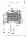
- FIG. figure 2 an exemplary liquid heating device according to a first embodiment indicated by the general reference numeral 1, integrated in a coffee machine 2 (FIG. figure 2 ) which may be indifferently intended for household or industrial use.
- the nature of the liquid to be heated in the heating device is not critical and that the liquid may be any such as water, milk, a chocolate drink, etc.
- the liquid to be heated is water.
- the coffee machine 2 illustrated in figure 2 comprises a cold water tank 4 connected via a pipe 6 to a pump 8 which supplies water to the heating device 1 via a liquid inlet 10. The water flows through a channel 12 provided in a body 13 of the heating 1.
- the channel 12 is associated with heating bodies 14a, 14b, 14c and 14d, whose power supply is controlled by switching means 16 connected to control means 18.
- the heating bodies are thus immersed in the liquid to be heated and in direct contact with it.
- the water exits the heater via a liquid outlet 20 and then flows through a conduit 22 to arrive through a conduit 24 on a cartridge 26 containing a substance for forming a beverage such as coffee from roasted coffee and ground or soluble coffee, tea, chocolate or other hot drinks.
- the cartridge 26 is, for example, a sealed cartridge which opens under the pressure of the liquid as described in European Patent No 512,468 .
- the coffee then flows into a cup 28.
- the machine also makes it possible to produce steam via a duct 30 connected to the duct 22. figure 1 the direction of flow of water through the heater is indicated by arrows A and B.
- the channel 12 comprises four channel portions 12a, 12b, 12c and 12d, successively interconnected by three connecting ducts 32ab, 32bc and 32cd.
- the channel portions 12a, 12b, 12c and 12d each define a chamber that receives a heater body 14a, 14b, 14c and 14d.
- the connecting conduits 32ab, 32bc and 32cd have cross sections smaller than those of the chambers 12a, 12b, 12c and 12d.
- the chambers 12a, 12b, 12c and 12d are arranged parallel to each other and juxtaposed in a block 13a that includes the body 13.
- the chambers 12a, 12b, 12c and 12d all open on a first side of the block 13a at a first end whereby the heating bodies 14a, 14b, 14c and 14d are introduced into the chambers 12a, 12b, 12c and 12d.
- the second ends of the chambers 12a, 12b, 12c and 12d open on a second side of the block 13a opposite the first and the chambers 12a, 12b, 12c and 12d are interconnected at one of their ends by the three connecting ducts 32ab, 32bc and 32cd.
- the chamber 12a is connected on the one hand to the liquid inlet 10 via a duct 36 at its end disposed on the second side of the block 13a and on the other hand to the chamber 12b via the connecting duct 32ab by its end disposed of the first side of the block 13a.
- the chamber 12b is connected to the chamber 12c via the connecting pipe 32bc by its end disposed on the second side of the block 13a.
- the chamber 12c is connected to the chamber 12d via the connecting pipe 32cd by its end disposed on the first side of the block 13a and the chamber 12d is connected to the liquid outlet 20 via a pipe 38 by its end disposed on the second side of the block 13a.
- each heating body 14a, 14b, 14c and 14d extends substantially over the entire length of the chamber with which it is associated and has a shape substantially complementary to that of the chamber with which it is associated.
- the outer surface of the heating bodies and / or the inner wall of the chamber associated therewith has a helical groove, which makes it possible to lengthen the path of the liquid during which it is in contact with the heating bodies and its speed; therefore increase the coefficient heat exchange; without thereby increasing the size of the heater.
- the heating device 1 further comprises a temperature sensor 40 disposed in the conduit 36 connecting the liquid inlet to the inlet of the chamber 12a.
- This sensor 40 is arranged to come into direct contact with the liquid to be heated and to measure the temperature of the liquid to be heated at the inlet of the heating device, that is to say before it has come into contact with one of the heating bodies of the device 1.
- a flowmeter 42 is also provided in the duct 36, thus upstream of the chamber 12a.
- the body 13 further comprises two covers 44, 46 which respectively extend from the first and second side of the block 13a and cover the two ends of each of the chambers 12a, 12b, 12c and 12d.
- the cover 44 which is on the first side of the block 13a carries the heating bodies 14a, 14b, 14c, and 14d while the cover 46 which is on the second side of the block 13a carries an intermediate temperature sensor 48.
- the sensor intermediate temperature 48 is associated with the connecting conduit 32bc and is arranged to come into direct contact with the liquid to be heated circulating in the conduit.
- the inlet temperature sensor 40, the flow meter and the intermediate temperature sensor 48 are connected to the control means 18 of the device 1.
- the cover 44 closes a first end of the chambers 12a, 12b, 12c and 12d and further delimits with the block 13a the connecting conduits 32ab and 32cd.
- the lid 46 closes the second end of the chambers 12a, 12b, 12c and 12d and delimits the conduit 32bc with the block 13a.
- the cover 46 further defines a channel 36a connecting the conduit 36 to the chamber 12a and the channel 38a connecting the chamber 12d to the conduit 38.
- the covers 44 and 46 are fixed to the block 13a by means of screws (not shown ) and the seal is provided by O ring seals 44a, 46a interposed between the covers 44, 46 and the block 13a.
- the control means 18 and the switching means 16 are configured to control the heating bodies 14a, 14b, 14c and 14d. These control means 16 are particularly designed to control the heating bodies 14c and 14d disposed respectively in the chambers 12c, 12d located downstream of the intermediate temperature sensor 48 as a function of the amount of useful energy to be supplied in the chambers 12c and 12d for bringing the liquid to be heated from the intermediate temperature measured by the intermediate temperature sensor 48 to a set temperature contained, for example, in a memory of the control means 18.
- the heating bodies 14a, 14b, 14c, and 14d each comprise a resistor.
- the resistors are connected to the switching means 16 and the control means 18 are arranged so as to be able to switch the resistors independently of one another.
- the principle of energy distribution is based on the pulses given by the flow meter (for example every 100 ms or less). At each pulse of the flow meter corresponds energy or a given heating time on the heating bodies. This proportional system makes it possible to react to rapid variations in the flow rate; this may be the case during the extraction cycle of a capsule, in particular, at the time of piercing the capsule.
- Each resistor develops a nominal power lower than the theoretical flicker power value of the network, typically less than 450W at 230V.
- the maximum power that can be switched over the entire frequency range is about 380W.
- the control means 18 are arranged to switch the resistances of the heating elements from the "on" state to the "off” state. and vice versa intermittently and non-simultaneously. Switching is always done at the zero crossing of the voltage to prevent the introduction of disturbance in the electrical network.
- the control means 18 further comprise regulating means which are provided for calculating the amount of energy to be allocated to the heating bodies 14c, 14d disposed in the channel portions 12c, 12d located downstream of the intermediate temperature sensor 48, depending on the input and intermediate temperatures measured and the flow rate measured by the flowmeter 42. Other factors may be taken into account in the calculation of the quantity of energy, in particular the measurement of the mains voltage (for example 230V ).
- the amount of energy can be corrected by a correction factor based on the fluctuation between the actually measured mains voltage and the nominal nominal voltage. This factor indicates whether the actual voltage is higher or lower than the nominal voltage, for example 230V. This factor is updated when the resistors are switched on in order to also take into account voltage drops in the supply line.
- the control means generally comprise a microcontroller, memory and energy balance calculation programs and correction factors to be applied. Calculations of energy balances, corrections and switching of the heating bodies by the microcontroller are made at very short time intervals so as to constantly regulate the amounts of energy supplied to the heating bodies.
- the intervals for calculating energy quantities are, in the order of a few milliseconds, preferably less than 100 ms, for example every 30 ms.
- the automatic regulation mode is based on the following principle.
- a temperature measurement of the liquid at the inlet of the device is taken by the temperature sensor 40 at the input of the device; the amount of liquid to be heated is taken by a flow meter 42 on the basis of pulses.
- An intermediate temperature between the first and second heating body is also measured by the temperature sensor 48.
- the system can start from a temperature of theoretical input, typically the temperature of the water network, stored in a microcontroller.
- the microcontroller comprising a program for calculating the quantities of energy.
- the intermediate temperature of setpoint is a value determined by calculation during tests of the device and which corresponds to an optimal theoretical value as a function of the measured temperature of the water at the inlet, the set outlet temperature (set point), a factor 230V network correction, the theoretical values of the ohmic resistances of the heating elements. This value varies depending on the desired outlet temperature, for example, for the production of a coffee or other beverage such as chocolate. This value is stored in the program or in a memory of the microcontroller.
- the microcontroller also calculates the quantity of theoretical energy to be supplied by the second heating element according to the formula:
- Quantity of energy for the second heating element Quantity of liquid to be heated measured by the flow meter x (desired outlet temperature - measured intermediate temperature) x heat capacity of the liquid. This amount of energy can also be corrected to account for the grid voltage.
- the microcontroller then controls the distribution of these calculated energy quantities, per heating time unit, by controlling the switching on / off of the resistances contained in the heating bodies.
- the correction factor is then applied by the microcontroller to adjust the amount of energy required to heat the liquid in the second chamber to obtain the temperature closest to the desired temperature output of the heating block.
- the correction factor is less than 1; this means that the amount of real energy distributed by the heating body (s) upstream of the intermediate temperature probe is too low and it is therefore necessary to apply a correction by increasing the amount of energy distributed by the (s) heater located downstream of the intermediate temperature probe.
- the factor is greater than 1, it means that the amount of real energy distributed by the heating body (s) upstream of the intermediate temperature probe is too high; and it is then necessary to apply a correction by decreasing the amount of energy distributed by the heating body (s) located downstream of this probe.
- the correction factor is calculated at a value of 1.10; this means that the amount of energy distributed by the first heater (s) is 10% too high and it will then be necessary to apply a reduction in the amount of energy to the second heater (s) by 10% for to obtain an exit temperature approaching as close as possible to the desired temperature.
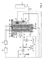
- This heating device is distinguished from that described above only in that the channel 12 provided in the body 13 and through which the liquid to be heated circulates comprises only two channel portions 12e and 12f interconnected by a conduit of 32ef link which is associated with the intermediate temperature sensor 48 and that the heating bodies 14e and 14f respectively associated with the channel portions 12e and 12f each comprise two resistors, each of them being connected to the control means 18 via the switching means 16.
- the electrical resistances of the heating bodies 14e and 14f each develop a nominal power lower than the theoretical flicker power value typically less than 450W at 230V and the control means 18 are arranged. to switch these resistors from the "on" state to the "off” state and vice versa intermittently typically at a frequency of the order of 10 ms.
- Heating bodies of this type are, for example, so-called “high-charge” or “high-density” heating cartridges; that is, developing a significant power per unit area of heating.
- FIG 5 is schematically shown a coffee machine incorporating another aspect of the invention.
- the elements identical to those described in connection with the figure 4 are designated by the same reference numerals.
- This coffee machine differs from that described above in that it comprises a device for ensuring the delivery of a "first" liquid or a "first” steam at the appropriate temperature.
- the device comprises a first main duct 22 connected to the extraction device 26.
- a counter-pressure valve 24a of the duct 24 is disposed at the inlet of the device 26.
- a first solenoid valve 50a is connected to a portion of the duct 22a leading to a drainage tank 52.
- a second so-called “steam” solenoid valve 50b is connected to the duct 30 disposed between the first user device and the second user device formed in the example by a steam ejection nozzle 56.
- the solenoid valves 50a, 50b are controlled by the control means 18.
- the solenoid valves 50a, 50b are arranged to respectively control the solenoid valves 50a, 50b so as to direct the fluid from the fluid outlet 20 to either of the two user devices, or to the tank of drainage 52 depending on whether or not the temperature measured by the sensor 48 reaches the set temperature for the user device under consideration.
- the drain pan may be replaced by a recirculation loop returning to the inlet 10 of the heater. Recirculation, however, complicates the device because it may require a pump additional.
- the set temperature is obtained after only a few seconds and the quantity of water rejected is therefore generally low.
Landscapes
- Engineering & Computer Science (AREA)
- Physics & Mathematics (AREA)
- General Engineering & Computer Science (AREA)
- Thermal Sciences (AREA)
- Chemical & Material Sciences (AREA)
- Combustion & Propulsion (AREA)
- Mechanical Engineering (AREA)
- Fluid Mechanics (AREA)
- Food Science & Technology (AREA)
- Computer Hardware Design (AREA)
- Control Of Resistance Heating (AREA)
- Apparatus For Making Beverages (AREA)
- Instantaneous Water Boilers, Portable Hot-Water Supply Apparatuses, And Control Of Portable Hot-Water Supply Apparatuses (AREA)
- Cookers (AREA)
- Resistance Heating (AREA)
- Control Of Temperature (AREA)
Claims (31)
- Vorrichtung (1) zum Erhitzen eines Fluids in Form von heißer Flüssigkeit oder Dampf für die Zubereitung von Kaffee oder anderen heißen Getränken, umfassend einen Körper (13), der mit einem Kanal (12) für den Umlauf eines Fluids versehen ist, der einen Fluideintritt (10) und einen Fluidaustritt (20) aufweist und dem mindestens ein elektrischer Heizkörper (14a, 14b, 14c, 14d) zugeordnet ist, dessen Versorgung durch Schaltmittel (16) gesteuert wird, die mit Steuermitteln (18) verbunden sind, wobei dieser Kanal mindestens einen ersten und einen zweiten Kanalabschnitt (12a, 12b, 12c, 12d) umfasst, die miteinander durch einen dritten, eine Verbindungsleitung bildenden Kanalabschnitt (32ab, 32bc, 32cd) verbunden sind, dem mindestens ersten und zweiten Kanalabschnitt (12a, 12b, 12c, 12d) jeweils mindestens ein Heizkörper zugeordnet ist, der Verbindungsleitung ein mit den Steuermitteln verbundener Mitteltemperaturfühler (48) zugeordnet ist, der Mitteltemperaturfühler ausgebildet ist, um die Temperatur des in dieser Leitung strömenden Fluids zu messen, wobei diese Vorrichtung dadurch gekennzeichnet ist, dass sie einen Durchsatzmesser (42) umfasst, der die den Kanal durchquerende Fluidmenge misst, und dass die Steuerund Schaltmittel ausgebildet sind, um den Heizkörper des mindestens zweiten Kanalabschnitts in Abhängigkeit von der Nutzenergiemenge zu steuern, die in dem zweiten Kanalabschnitt zuzuführen ist, um das zu erhitzende Fluid von der von dem Mitteltemperaturfühler gemessenen Mitteltemperatur auf eine Solltemperatur am Austritt der Vorrichtung zu bringen, wobei diese Energiemenge von den Steuermitteln in Abhängigkeit von der von dem Durchsatzmesser gemessenen Fluidmenge, der gemessenen Mitteltemperatur und der Solltemperatur am Austritt der Vorrichtung errechnet wird und diese Energiemenge durch die Steuerund Schaltmittel in bestimmten Zeitintervallen an den Heizkörper des mindestens zweiten Kanalabschnitts abgegeben wird.
- Vorrichtung zum Erhitzen eines Fluids nach Anspruch 1, dadurch gekennzeichnet, dass die bestimmten Zeitintervalle kleiner als oder gleich 500 Millisekunden sind.
- Vorrichtung zum Erhitzen eines Fluids nach Anspruch 1 oder 2, dadurch gekennzeichnet, dass die Heizkörper in das zu erhitzende Fluid eingetaucht sind.
- Vorrichtung nach einem der Ansprüche 1 bis 3, dadurch gekennzeichnet, dass sie außerdem einen Fluideingangstemperaturfühler (40), der so angeordnet ist, dass er mit dem Fluid am Eintritt der Vorrichtung in direkten Kontakt kommt, und einen stromauf des Eintritts der ersten Kammer angeordneten Durchsatzmesser umfasst.
- Vorrichtung nach Anspruch 4, dadurch gekennzeichnet, dass Regelmittel (16, 18) vorgesehen sind, um einen Faktor zur Korrektur der Leistung zu berechnen, die an den Heizkörper des zweiten Kanalabschnitts in Abhängigkeit von der gemessenen Eintrittstemperatur und der gemessenen Mitteltemperatur anzulegen ist.
- Vorrichtung nach einem der Ansprüche 1 bis 5, dadurch gekennzeichnet, dass jeder Heizkörper mindestens einen Widerstand umfasst, wobei jeder Widerstand jedes Heizkörpers unabhängig schaltbar ist.
- Vorrichtung nach Anspruch 6, dadurch gekennzeichnet, dass die Heizkörper in der Anzahl von zwei vorgesehen sind und jeweils zwei Widerstände umfassen, wobei jeder Heizwiderstand der beiden Heizkörper so ausgebildet ist, dass er durch die Schaltmittel (16) voneinander unabhängig geschaltet werden kann.
- Vorrichtung nach Anspruch 6, dadurch gekennzeichnet, dass die Heizkörper in der Anzahl von vier vorgesehen sind, wobei jeder in einem getrennten Kanalabschnitt untergebracht ist und jeder einen Widerstand umfasst, wobei jeder Widerstand ausgebildet ist, um durch die Schaltmittel unabhängig geschaltet zu werden.
- Vorrichtung nach Anspruch 6, 7 oder 8, dadurch gekennzeichnet, dass jeder Widerstand eine Nennleistung entwickelt, die niedriger als der theoretische Schwankungsleistungswert des Netzes ist, und dass die Widerstände in einer Stellung Ein-Aus durch die Schaltmittel versetzt geschaltet werden, um die Leistungsdifferenzen als absoluter Werten, die höher als die Nennleistung jedes der Widerstände sind, zu vermeiden.
- Vorrichtung nach Anspruch 8, dadurch gekennzeichnet, dass jeder Widerstand eine elektrische Nennleistung kleiner als 450 W entwickelt.
- Vorrichtung zum Erhitzen eines Fluids nach einem der vorhergehenden Ansprüche, dadurch gekennzeichnet, dass die dem mindestens einen Heizkörper zugeordneten Kanalabschnitte jeweils Klammern bilden, die durch eine Verbindungsleitung miteinander verbunden sind, die einen Querschnitt aufweist, der kleiner als derjenige der Kammern ist.
- Vorrichtung zum Erhitzen eines Fluids nach Anspruch 11, dadurch gekennzeichnet, dass die Außenfläche der Heizkörper und/oder die Innenwand der ihr zugeordneten Kammer eine Schraubennutung aufweist.
- Vorrichtung nach einem der Ansprüche 11 oder 12, dadurch gekennzeichnet, dass der Körper einen Block umfasst, in dem die Kammern vorgesehen sind, dass die Kammern zueinander parallel sind und zu beiden Seiten des Blocks ausmünden, dass sie miteinander an einem ihrer Enden durch eine Verbindungsleitung verbunden sind und dass der Körper außerdem zwei Deckel umfasst, die erste bzw. zweite Enden der Kammern abdecken.
- Vorrichtung nach Anspruch 13, dadurch gekennzeichnet, dass der erste Deckel, der ersten Enden der Kammern zugeordnet ist, die Heizkörper (12a, 12b, 12c, 12d) trägt und dass der zweite Deckel, der den zweiten Enden der Kammern zugeordnet ist, den Mitteltemperaturfühler (48) trägt.
- Vorrichtung nach Anspruch 14, dadurch gekennzeichnet, dass der erste und der zweite Deckel mit dem Block den oder die Verbindungsleitungen begrenzen.
- Vorrichtung nach Anspruch 14, dadurch gekennzeichnet, dass der zweite Fühler und der Durchsatzmesser in einer Leitung angeordnet sind, die in dem Block vorgesehen ist und den Fluideintritt mit dem Eintritt einer ersten Kammer verbindet.
- Vorrichtung nach Anspruch 13, dadurch gekennzeichnet, dass jeder Heizkörper sich über die ganze Länge der Kammer erstreckt, der er zugeordnet ist, und dass er eine Form besitzt, die zu derjenigen der Kammer, der er zugeordnet ist, komplementär ist.
- Vorrichtung nach einem der vorhergehenden Ansprüche, dadurch gekennzeichnet, dass der Mitteltemperaturfühler (48) stromab der mit dem Fluideintritt verbundenen Kammer und stromauf der mit dem Fluidaustritt verbundenen Kammer angeordnet ist.
- Verfahren zum schnellen und genauen Erhitzen eines Fluids für die Zubereitung von Kaffee oder anderen Getränken mit Hilfe einer Heizvorrichtung, die einen Körper umfasst, der mit einem Kanal für den Umlauf des Fluids, mit mindestens einem ersten Heizkörper und mindestens einen zweiten Heizkörper versehen ist, dadurch gekenntzeichnet, dassa) die zu erhitzende Fluidmenge durch einen Durchsatzmesser (42) gemessen wird,b) die Mitteltemperatur durch einen Mitteltemperaturfühler (48) gemessen wird, der in direktem oder indirektem Kontakt mit dem Fluid zwischen dem ersten und dem zweiten Heizkörper (12a, 12b, 12c, 12d) angeordnet ist,c) die theoretische Energiemenge, die von dem zweiten Heizkörper zu liefern ist, durch das Steuermittel in Abhängigkeit von der gemessenen zu erhitzenden Fluidmenge, von der gemessenen Mitteltemperatur, von der Solltemperatur am Austritt der Vorrichtung und von der Wärmekapazität des Fluids berechnet wird,d) diese errechnete Energiemenge durch das Schaltmittel jeweilig an die zweiten Heizkörper durch selektive Schaltung der Heizkörper angelegt wird, um das Fluid auf die gewünschte Solltemperatur am Austritt der Vorrichtung (oder zumindest möglichst nahe zu dieser) zu bringen,e) mindestens mehrere der Schritte a) bis d) durch das Steuermittel in bestimmten Zeitintervallen wiederholt werden.
- Verfahren zum schnellen und genauen Erhitzen eines Fluids nach Anspruch 19, dadurch gekennzeichnet, dass mindestens mehrer der Schritte a) bis d) in Zeitintervallen wiederholt werden, die kleiner als oder gleich 500 Millisekunden sind.
- Verfahren nach Anspruch 19 oder 20, dadurch gekennzeichnet, dass die im Schritt d) abgegebene Energiemenge bei oder nach jedem Impuls des Durchsatzmessers während des Schritts a) abgegeben wird.
- Verfahren nach Anspruch 21, dadurch gekennzeichnet, dass das Intervall für die Berechnung der Energiemenge im Schritt c) etwa 30 ms beträgt.
- Verfahren nach Anspruch 19 zum schnellen und genauen Erhitzen eines Fluids insbesondere für Haushaltsanwendungen und vor allem für die Zubereitung von Kaffee oder anderen Getränken mit Hilfe einer Heizvorrichtung, die einen Körper umfasst, der mit einem Kanal für den Umlauf des Fluids, mit mindestens einem ersten Heizkörper und mindestens einem zweiten Heizkörper versehen ist, dadurch gekennzeichnet, dassf) die Temperatur des Fluids am Eintritt der Vorrichtung durch einen Fluideintrittstemperaturfühler gemessen wird, der in direktem oder indirektem Kontakt mit dem Fluid angeordnet ist,g) die zu erhitzende Fluidmenge durch einen Durchsatzmesser gemessen wird,h) die theoretische Energiemenge, die von dem ersten Heizkörper zu liefern ist, durch ein Steuermittel in Abhängigkeit von der gemessenen Fluidmenge, von der am Eintritt der Vorrichtung gemessenen Temperatur, von einer Sollmitteltemperatur und von der Wärmekapazität des Fluids errechnet wird,i) die Mitteltemperatur durch einen Mitteltemperaturfühler gemessen wird, der in direktem oder indirektem Kontakt mit dem Fluid zwischen dem ersten und dem zweiten Heizkörper angeordnet ist,j) die theoretische Energiemenge, die von dem zweiten Heizkörper zu liefern ist, durch das Steuermittel in Abhängigkeit von der gemessenen zu erhitzenden Fluidmenge, von der gemessenen Mitteltemperatur, von der Solltemperatur am Austritt der Vorrichtung und von der Wärmekapazität des Fluids berechnet wird,k) diese errechneten Energiemengen durch das Schaltmittel jeweilig an die ersten und zweiten Heizkörper durch selektive Schaltung der Heizkörper angelegt werden, um das Fluid auf die gewünschte Solltemperatur am Austritt der Vorrichtung (oder zumindest möglichst nahe zu dieser Solltemperatur) zu bringen,l) mindestens mehrere der Schritte f) bis k) durch das Steuermittel in bestimmten Zeitintervallen wiederholt werden.
- Verfahren zum schnellen und genauen Erhitzen eines Fluids nach Anspruch 23, dadurch gekennzeichnet, dass mindestens mehrere der Schritte f) bis k) in Zeitintervallen wiederholt werden, die kleiner als oder gleich 500 Millisekunden sind.
- Verfahren nach Anspruch 23 oder 24, dadurch gekennzeichnet, dass die im Schritt k) abgegebenen Energiemenge bei oder nach jedem Impuls des Durchsatzmessers während des Schritts g) abgegeben werden.
- Verfahren nach Anspruch 24, dadurch gekennzeichnet, dass das Intervall für die Berechnungen der Energiemengen in den Schritt h) und j) etwa 30 ms beträgt.
- Verfahren nach Anspruch 24, 25 oder 26, dadurch gekennzeichnet, dass
man einen Korrekturfaktor nach der Formel berechnet:
man diesen Korrekturfaktor bei der Berechnung der von dem zweiten Heizkörper zu liefernden Energiemenge anlegt. - Vorrichtung zum Erhitzen eines Fluids nach Anspruch 1, dadurch gekennzeichnet, dass ein Fluidaustritt durch eine Leitung mit einer verbrauchenden Vorrichtung verbunden ist und dass dies Heizvorrichtung außerdem mindestens ein Magnetventil (50a) umfasst, das mit dieser Leitung zwischen dem Fluidaustritt und der verbrauchenden Vorrichtung verbunden ist und das durch die Steuermittel (18) gesteuert wird, und dass die Steuermittel ausgebildet sind, um das Magnetventil so zu steuern, dass das vom Fluidaustritt kommende Fluid zu einem Ablaufbehälter oder zu einer Rezirkulierungsschleife geleitet wird, wenn die von dem Fühler gemessene Temperatur die Solltemperatur noch nicht erreicht hat, und zu der verbrauchende Vorrichtung geleitet wird, wenn die gemessene Temperatur die Solltemperatur erreicht hat.
- Vorrichtung nach Anspruch 28, dadurch gekennzeichnet, dass die verbrauchende Vorrichtung eine Einheit zum Extrahieren einer in einer Kartusche (26) enthaltenen Substanz und/oder eine Dampfausstoßdüse umfasst.
- Vorrichtung nach Anspruch 28 oder 29, dadurch gekennzeichnet, dass die Vorrichtung außerdem stromab der verbrauchenden Vorrichtung angeordnete Mittel umfasst, die die Erzeugung eines Gegendrucks gestatten, und dass das Magnetventil (50a) ein Einfachventil ist, das in einer Zweigleitung der Leitung angeordnet ist.
- Vorrichtung nach Anspruch 28 oder 29, dadurch gekennzeichnet, dass das Magnetventil (50a) ein in der Leitung angeordnetes Dreiwegeventil ist, wobei die drei Wege mit dem Fluidaustritt, mit dem Ablaufbehälter bzw. mit der verbrauchenden Vorrichtung verbunden sind.
Priority Applications (3)
| Application Number | Priority Date | Filing Date | Title |
|---|---|---|---|
| EP05782895A EP1809151B1 (de) | 2004-09-13 | 2005-09-09 | Vorrichtung und verfahren zum erhitzen einer flüssigkeit |
| PL05782895T PL1809151T3 (pl) | 2004-09-13 | 2005-09-09 | Urządzenie podgrzewające płyn i sposób podgrzewania płynu |
| EP07124079A EP1913851B1 (de) | 2004-09-13 | 2005-09-09 | Vorrichtung zum Erhitzen einer Flüssigkeit und Verfahren zum Erhitzen einer Flüssigkeit |
Applications Claiming Priority (3)
| Application Number | Priority Date | Filing Date | Title |
|---|---|---|---|
| EP04021674A EP1634520A1 (de) | 2004-09-13 | 2004-09-13 | Vorrichtung zur Heizung einer Flüssigkeit und Verfahren zum Erhitzen einer Flüssigkeit |
| EP05782895A EP1809151B1 (de) | 2004-09-13 | 2005-09-09 | Vorrichtung und verfahren zum erhitzen einer flüssigkeit |
| PCT/EP2005/009689 WO2006029763A2 (fr) | 2004-09-13 | 2005-09-09 | Dispositif de chauffage d'un liquide et procede pour chauffer un liquide |
Related Child Applications (1)
| Application Number | Title | Priority Date | Filing Date |
|---|---|---|---|
| EP07124079A Division EP1913851B1 (de) | 2004-09-13 | 2005-09-09 | Vorrichtung zum Erhitzen einer Flüssigkeit und Verfahren zum Erhitzen einer Flüssigkeit |
Publications (2)
| Publication Number | Publication Date |
|---|---|
| EP1809151A2 EP1809151A2 (de) | 2007-07-25 |
| EP1809151B1 true EP1809151B1 (de) | 2008-09-10 |
Family
ID=34926511
Family Applications (3)
| Application Number | Title | Priority Date | Filing Date |
|---|---|---|---|
| EP04021674A Withdrawn EP1634520A1 (de) | 2004-09-13 | 2004-09-13 | Vorrichtung zur Heizung einer Flüssigkeit und Verfahren zum Erhitzen einer Flüssigkeit |
| EP05782895A Expired - Lifetime EP1809151B1 (de) | 2004-09-13 | 2005-09-09 | Vorrichtung und verfahren zum erhitzen einer flüssigkeit |
| EP07124079A Expired - Lifetime EP1913851B1 (de) | 2004-09-13 | 2005-09-09 | Vorrichtung zum Erhitzen einer Flüssigkeit und Verfahren zum Erhitzen einer Flüssigkeit |
Family Applications Before (1)
| Application Number | Title | Priority Date | Filing Date |
|---|---|---|---|
| EP04021674A Withdrawn EP1634520A1 (de) | 2004-09-13 | 2004-09-13 | Vorrichtung zur Heizung einer Flüssigkeit und Verfahren zum Erhitzen einer Flüssigkeit |
Family Applications After (1)
| Application Number | Title | Priority Date | Filing Date |
|---|---|---|---|
| EP07124079A Expired - Lifetime EP1913851B1 (de) | 2004-09-13 | 2005-09-09 | Vorrichtung zum Erhitzen einer Flüssigkeit und Verfahren zum Erhitzen einer Flüssigkeit |
Country Status (26)
| Country | Link |
|---|---|
| US (2) | US7907835B2 (de) |
| EP (3) | EP1634520A1 (de) |
| JP (1) | JP5048499B2 (de) |
| KR (2) | KR101235440B1 (de) |
| CN (1) | CN101060803B (de) |
| AR (1) | AR055254A1 (de) |
| AT (1) | ATE407607T1 (de) |
| AU (1) | AU2005284369B2 (de) |
| BR (1) | BRPI0515262A (de) |
| CA (2) | CA2792130A1 (de) |
| DE (2) | DE602005009733D1 (de) |
| DK (1) | DK1809151T3 (de) |
| ES (2) | ES2314707T3 (de) |
| HR (1) | HRP20070098A2 (de) |
| IL (1) | IL181503A (de) |
| MA (1) | MA28852B1 (de) |
| MX (1) | MX2007002994A (de) |
| NO (1) | NO20071907L (de) |
| PL (1) | PL1809151T3 (de) |
| PT (2) | PT1809151E (de) |
| RU (1) | RU2367328C2 (de) |
| SG (1) | SG155933A1 (de) |
| TN (1) | TNSN07092A1 (de) |
| TW (1) | TWI274572B (de) |
| WO (1) | WO2006029763A2 (de) |
| ZA (1) | ZA200703020B (de) |
Cited By (7)
| Publication number | Priority date | Publication date | Assignee | Title |
|---|---|---|---|---|
| US8479640B2 (en) | 2007-10-04 | 2013-07-09 | Nestec S.A. | Beverage brewing unit |
| US8573116B2 (en) | 2007-10-04 | 2013-11-05 | Nestec S.A. | Heating device with an integrated thermoblock for a beverage preparation machine |
| US8600223B2 (en) | 2007-10-04 | 2013-12-03 | Nestec S.A. | Integrated heater for a beverage preparation device |
| US8850957B2 (en) | 2008-04-22 | 2014-10-07 | Nestec S.A. | Modular assembly of a beverage preparation machine |
| US8863648B2 (en) | 2009-03-23 | 2014-10-21 | Nestec S.A. | Pump mount in a beverage preparation machine |
| US8915177B2 (en) | 2008-08-08 | 2014-12-23 | Nestec S.A. | Beverage machine with carrying handle and configurable appearance and side functions |
| US9277839B2 (en) | 2010-07-12 | 2016-03-08 | Nestec S.A. | Secure cup support for beverage machine |
Families Citing this family (139)
| Publication number | Priority date | Publication date | Assignee | Title |
|---|---|---|---|---|
| EP1495702A1 (de) | 2003-07-10 | 2005-01-12 | Nestec S.A. | Vorrichtung zur Extraktion einer Kartusche |
| EP1634520A1 (de) * | 2004-09-13 | 2006-03-15 | Nestec S.A. | Vorrichtung zur Heizung einer Flüssigkeit und Verfahren zum Erhitzen einer Flüssigkeit |
| DE102006029061B4 (de) * | 2006-06-24 | 2009-03-12 | Aesculap Ag | Halteelement für ein Haltesystem für medizinische Gegenstände und Haltesystem für medizinische Gegenstände |
| GB2447480A (en) * | 2007-03-14 | 2008-09-17 | Michael Hughes | Temperature control of a liquid |
| US8165461B2 (en) * | 2007-05-07 | 2012-04-24 | Sullivan Joseph M | Modular heating system for tankless water heater |
| FR2920657B1 (fr) * | 2007-09-07 | 2013-02-22 | Cie Mediterraneenne Des Cafes | Chaudiere pour machine de preparation de boissons. |
| IL186784A0 (en) * | 2007-10-18 | 2008-02-09 | Coffee And Juice Generation Lt | Systems and methods for preparing drinks |
| WO2009084060A1 (en) * | 2008-01-03 | 2009-07-09 | Essence-Sbt Sa | Delivering system for infusion-type beverages |
| DK2252182T3 (da) | 2008-01-24 | 2012-07-23 | Nestec Sa | Energisparestyring til drikketilberedningsindretninger |
| EP2082669A2 (de) | 2008-01-25 | 2009-07-29 | Nestec S.A. | Hybridvorrichtung für die Getränkezubereitung |
| US8043645B2 (en) | 2008-07-09 | 2011-10-25 | Starbucks Corporation | Method of making beverages with enhanced flavors and aromas |
| DE202009015187U1 (de) * | 2008-11-14 | 2010-06-24 | Koninklijke Philips Electronics N.V. | Einsatzteil für einen Durchlauferhitzer |
| RU2535461C2 (ru) | 2009-02-06 | 2014-12-10 | Нестек С.А. | Устройство и способ, использующие центрифугирование для экстракции жидкости, и средства компенсации тепловых потерь |
| EP2223641B1 (de) | 2009-02-18 | 2016-05-11 | Nestec S.A. | Heizvorrichtung mit mehrfachen Leistungseinstellungen |
| US8208800B2 (en) * | 2009-03-16 | 2012-06-26 | Hsien Mu Chiu | Potable water heating device |
| EP2410894B2 (de) | 2009-03-23 | 2021-06-30 | Société des Produits Nestlé S.A. | Pumpenhalterung in einer getränkezubereitungsmaschine |
| EP3493167A1 (de) | 2009-12-02 | 2019-06-05 | Nestec S.A. | Eine ferndienstleistungsfunktion unterstützende getränkeherstellungsmaschine |
| RU2553196C2 (ru) | 2010-01-06 | 2015-06-10 | Нестек С.А. | Безвибрационный резервуар для воды аппарата для приготовления напитков |
| JP2011143780A (ja) * | 2010-01-13 | 2011-07-28 | Sanden Corp | 加熱装置 |
| JP2011143781A (ja) * | 2010-01-13 | 2011-07-28 | Sanden Corp | 加熱装置 |
| JP2011144976A (ja) * | 2010-01-13 | 2011-07-28 | Sanden Corp | 加熱装置 |
| PT2523586E (pt) | 2010-01-15 | 2014-09-09 | Nestec Sa | Suporte de ingrediente ergonómico e coordenação de unidade de serviço |
| ES2433439T3 (es) | 2010-01-15 | 2013-12-11 | Nestec S.A. | Unidad de servicio ergonómico para máquinas de preparación de bebidas |
| AU2011208657B2 (en) | 2010-01-21 | 2016-06-09 | Société des Produits Nestlé S.A. | Beverage machine with removable liquid supply reservoir |
| EP2353473A1 (de) | 2010-02-03 | 2011-08-10 | Nestec S.A. | Getränkespender mit hygienischem Reinigungszyklus |
| EP2353474A1 (de) | 2010-02-03 | 2011-08-10 | Nestec S.A. | Getränkespender mit sicherer Reinigungsanordnung |
| CN102781293B (zh) | 2010-03-05 | 2015-08-26 | 雀巢产品技术援助有限公司 | 用于饮料制备机器的泵和饮料制备机器 |
| EP2571407B1 (de) | 2010-05-21 | 2014-04-16 | Nestec S.A. | Lagerfähige warmwasser- oder dampfausgabevorrichtung |
| JP5881683B2 (ja) | 2010-05-21 | 2016-03-09 | ネステク ソシエテ アノニム | 人間工学的なディスペンサインターフェース |
| US9347682B2 (en) * | 2010-05-21 | 2016-05-24 | Nestec S.A. | Dynamic double-circuit in-line heater |
| EP2571408B1 (de) | 2010-05-21 | 2014-05-21 | Nestec S.A. | Getränkeautomat mit ergonomischer Wasserverwaltung |
| ES2464775T3 (es) | 2010-05-21 | 2014-06-04 | Nestec S.A. | Mango ergonómico e interfaz de usuario |
| PT2571406E (pt) | 2010-05-21 | 2014-06-02 | Nestec Sa | Processador de alimentos controlado remotamente |
| CA2801278A1 (en) | 2010-06-09 | 2011-12-15 | Nestec S.A. | Ergonomic service arrangement for beverage machine |
| CN102946776B (zh) | 2010-06-17 | 2016-08-03 | 雀巢产品技术援助有限公司 | 用于控制热调节装置的能量传输的设备和方法 |
| JP2013529524A (ja) | 2010-06-28 | 2013-07-22 | ネステク ソシエテ アノニム | カプセル感知システム |
| JP6018054B2 (ja) | 2010-07-16 | 2016-11-02 | ネステク ソシエテ アノニム | 高性能加熱装置 |
| IT1402968B1 (it) * | 2010-09-06 | 2013-09-27 | Iacobucci Hf Electronics S P A | Macchina per caffè da incasso |
| JP2013536717A (ja) | 2010-09-07 | 2013-09-26 | ネステク ソシエテ アノニム | ユーザインタフェースを有する人間工学的ハンドル |
| CN105747872B8 (zh) | 2010-10-27 | 2019-08-27 | 雀巢产品有限公司 | 用于不同空间环境的饮料机 |
| CA2819385A1 (en) | 2010-12-01 | 2012-06-07 | Nestec S.A. | Beverage machine with reliable user-indicator |
| CN103338683B (zh) | 2010-12-01 | 2016-08-10 | 雀巢产品技术援助有限公司 | 具有带门的胶囊通路的饮料机 |
| EP2645913B1 (de) | 2010-12-01 | 2014-06-18 | Nestec S.A. | Ergonomische benutzerschnittstelle für motorisierte mischungsbestandteilskammer |
| BR112013013533A2 (pt) | 2010-12-01 | 2016-10-18 | Nestec Sa | interface de usuário simples para uma máquina de bebidas |
| AU2011334903A1 (en) | 2010-12-01 | 2013-06-13 | Nestec S.A. | Beverage preparation machine with drop collector |
| KR20130121917A (ko) | 2010-12-02 | 2013-11-06 | 네스텍 소시에테아노님 | 음료 기계의 저관성 열 센서 |
| JP2012131331A (ja) * | 2010-12-21 | 2012-07-12 | Sanden Corp | 車両用加熱装置 |
| US8554064B1 (en) * | 2010-12-27 | 2013-10-08 | Msp Corporation | Method and apparatus for generating vapor at high rates |
| JP2014505531A (ja) | 2011-01-03 | 2014-03-06 | ネステク ソシエテ アノニム | 原材料入口用のカバーを有する飲料マシン |
| EP2661200B1 (de) | 2011-01-03 | 2019-04-24 | Nestec S.A. | Motorisierter getränkeautomat mit mechanischem getriebe |
| EP2474254A1 (de) | 2011-01-07 | 2012-07-11 | Nestec S.A. | Modulares Getränkeausgabesystem |
| DE202011001661U1 (de) * | 2011-01-19 | 2011-06-09 | Mahlich, Gotthard, 61476 | Brüh- oder Zubereitungskammer für ein Getränkezubereitungsgerät |
| EP2478804A1 (de) | 2011-01-21 | 2012-07-25 | Nestec S.A. | Milchaufschäumung mit Druckgas |
| CN102160750B (zh) * | 2011-02-16 | 2013-04-24 | 广东新宝电器股份有限公司 | 即热式发热煲体 |
| PT2489290E (pt) * | 2011-02-18 | 2015-01-14 | Gruppo Cimbali Spa | Um sistema melhorado para aquecimento da água numa caldeira e respectivo método |
| US10682004B2 (en) | 2011-03-23 | 2020-06-16 | Societe Des Produits Nestle S.A. | Beverage machine with a cover for an ingredient inlet |
| KR20120111906A (ko) * | 2011-04-01 | 2012-10-11 | 웅진코웨이주식회사 | 온수공급장치 및 온수공급방법 |
| CN103596472A (zh) * | 2011-05-27 | 2014-02-19 | 雀巢产品技术援助有限公司 | 具有可拆除的喷嘴旋转组件的饮料分配器 |
| USD677510S1 (en) | 2011-06-16 | 2013-03-12 | Calphalon Corporation | Coffee maker |
| WO2013029364A1 (zh) * | 2011-08-26 | 2013-03-07 | Chen Xiaoming | 优质热水的快速制备方法及装置 |
| US20140328136A1 (en) | 2011-09-16 | 2014-11-06 | Alfred Yoakim | Multi-system beverage machine safe connector |
| JP2014526325A (ja) | 2011-09-16 | 2014-10-06 | ネステク ソシエテ アノニム | 清浄なマルチシステム飲料マシン |
| AU2012307511A1 (en) | 2011-09-16 | 2014-03-06 | Nestec S.A. | Multi-system beverage machine multiple connections |
| GB201118226D0 (en) * | 2011-10-21 | 2011-12-07 | Strix Ltd | Flow heaters |
| US9149148B2 (en) | 2011-12-30 | 2015-10-06 | Nestec S. A. | Multi-system beverage machine |
| RU2617365C9 (ru) | 2012-01-13 | 2017-07-04 | Нестек С.А. | Машина для приготовления напитков для низких и высоких чашек |
| ES2617997T3 (es) | 2012-01-13 | 2017-06-20 | Nestec S.A. | Máquina de bebidas con un módulo extraíble |
| CN102538215A (zh) * | 2012-02-28 | 2012-07-04 | 苏州苏海亚电气有限公司 | 电加热器的温控装置 |
| EP2633789A1 (de) | 2012-02-28 | 2013-09-04 | Nestec S.A. | Getränkezubereitungsmaschine mit Tropfenhandhabung |
| WO2013127906A1 (en) | 2012-02-28 | 2013-09-06 | Nestec S.A. | Cover for an ingredient inlet with moisture management |
| CA2887322A1 (en) | 2012-10-09 | 2014-04-17 | Nestec S.A. | Beverage machine |
| US8934764B2 (en) * | 2012-11-05 | 2015-01-13 | Betacera Inc. | Electrical heating device and equipment with pluggable heating module |
| CN104981183B (zh) | 2012-12-12 | 2019-02-26 | 雀巢产品技术援助有限公司 | 利用离心作用来提取液体的包括热损失补偿装置的饮料生产设备 |
| GB201301297D0 (en) * | 2013-01-24 | 2013-03-06 | Strix Ltd | Liquid heating apparatus |
| EP3062667B1 (de) * | 2013-11-01 | 2017-03-22 | Koninklijke Philips N.V. | Flüssigkeitserhitzungsvorrichtung |
| FR3012872B1 (fr) * | 2013-11-07 | 2015-11-13 | Valeo Systemes Thermiques | Dispositif electrique de conditionnement thermique de fluide pour vehicule automobile, et appareil de chauffage et/ou de climatisation associe |
| CN105813509A (zh) | 2013-12-11 | 2016-07-27 | 雀巢产品技术援助有限公司 | 带有可枢转式胶囊出入口的饮料机 |
| US10188237B2 (en) | 2014-04-08 | 2019-01-29 | Nestec S.A. | Multisize capsule handling with serial actuation |
| EP3132654A4 (de) * | 2014-04-16 | 2018-01-31 | Spectrum Brands, Inc. | Kochgerät mit dünnschichtheizelement |
| AU2015101973A4 (en) * | 2014-05-09 | 2019-12-12 | Newell Australia Pty Ltd | Espresso machine |
| PT3166457T (pt) | 2014-07-09 | 2020-01-20 | Nestle Sa | Dispositivo para conectar uma máquina de bebidas a uma rede de distribuição com monitorização segura |
| EP3166456B1 (de) | 2014-07-09 | 2018-09-26 | Nestec S.A. | Zubehör zum automatischen versorgen einer getränkemaschine mit flüssigkeit aus einem verteilungsnetz |
| WO2016005351A1 (en) | 2014-07-09 | 2016-01-14 | Nestec S.A. | Coupling of a device for connecting a beverage machine to a distribution network |
| ES2828253T3 (es) | 2014-07-09 | 2021-05-25 | Nestle Sa | Dispositivo para conectar una máquina de bebidas a una red de distribución con interrupción segura de flujo |
| BR112017004206A2 (pt) * | 2014-09-05 | 2017-12-12 | Tuttoespresso Srl | aparelho de preparação de bebida e método para preparar uma bebida |
| EP3223667A1 (de) | 2014-11-27 | 2017-10-04 | Nestec S.A. | Ergonomische handgriffanordnung |
| CN106998940B (zh) | 2014-11-27 | 2020-04-28 | 雀巢产品有限公司 | 具有紧凑液滴止挡件的液体分配机器 |
| EP3223669B1 (de) | 2014-11-27 | 2020-02-19 | Société des Produits Nestlé S.A. | Flüssigkeitsausgabemaschine mit manuellem tropfstopp |
| DE102014118876A1 (de) * | 2014-12-17 | 2016-06-23 | Thyssenkrupp Ag | Verfahren zur Hochdruckbehandlung eines Produkts |
| TWI613405B (zh) * | 2015-07-24 | 2018-02-01 | 盈太企業股份有限公司 | 加熱器之結構 |
| ITUA20161428A1 (it) * | 2015-10-23 | 2017-09-07 | Eurek S R L | Metodo e macchina per la preparazione di bevande |
| WO2017068556A2 (en) * | 2015-10-23 | 2017-04-27 | Eurek S.R.L. | Method and machine for preparing beverages |
| US11284738B2 (en) | 2015-11-11 | 2022-03-29 | Societe Des Produits Nestle S.A. | Easy connection of a liquid tank to a beverage machine |
| WO2018001750A1 (en) | 2016-06-30 | 2018-01-04 | Nestec Sa | Beverage preparation machine with a controlled pump |
| BR112019001981A2 (pt) | 2016-09-09 | 2019-05-07 | Nestec S.A. | máquina de bebida com manuseio ergonômico |
| ES2835126T3 (es) | 2016-10-11 | 2021-06-21 | Nestle Sa | Máquina dispensadora de líquidos con regulador de velocidad |
| CN109715016A (zh) | 2016-10-11 | 2019-05-03 | 雀巢产品技术援助有限公司 | 具有液滴止挡件的液体分配机器 |
| WO2018158179A1 (en) | 2017-02-28 | 2018-09-07 | Nestec Sa | Dispenser with parallel dispensing paths |
| ES2965247T3 (es) | 2017-03-10 | 2024-04-11 | Nestle Sa | Máquina de preparación de bebidas y procedimiento para el control de un dispositivo de acondicionamiento térmico de dicha máquina de preparación de bebidas |
| CN107007153A (zh) * | 2017-04-13 | 2017-08-04 | 宁波云川环保科技有限公司 | 一种速热饮水机螺旋加热装置 |
| DK3638085T3 (da) | 2017-06-13 | 2021-03-29 | Nestle Sa | Driktilberedelsesmaskine med kapselgenkendelse |
| WO2019057618A1 (en) | 2017-09-25 | 2019-03-28 | Nestec Sa | BEVERAGE MACHINES WITH REMOVABLE MODULE |
| EP3687346A1 (de) | 2017-09-25 | 2020-08-05 | Société des Produits Nestlé S.A. | Getränkemaschinen mit modularität |
| IT201700119289A1 (it) * | 2017-10-20 | 2019-04-20 | Cma Macch Per Caffe Srl | Macchina per l’erogazione di caffe’ |
| JP7288443B2 (ja) | 2017-12-20 | 2023-06-07 | ソシエテ・デ・プロデュイ・ネスレ・エス・アー | 滴排出機能付き飲料調製マシン |
| AU2018387722B2 (en) | 2017-12-20 | 2024-11-07 | Societe Des Produits Nestle S.A. | Beverage preparation machine with handy drop stop |
| CA3086319A1 (en) | 2017-12-20 | 2019-06-27 | Societe Des Produits Nestle S.A. | Beverage preparation machine with foam refinement |
| AU2018408336B2 (en) | 2018-02-09 | 2025-02-20 | Societe Des Produits Nestle S.A. | Beverage preparation machine with capsule recognition |
| US11819155B2 (en) | 2018-02-14 | 2023-11-21 | Societe Des Produits Nestle S.A. | Used capsule receptacle for beverage machines |
| AU2019233587A1 (en) | 2018-03-14 | 2020-08-06 | Societe Des Produits Nestle S.A. | Beverage machine with a controlled outflow aperture |
| AU2019233586A1 (en) | 2018-03-14 | 2020-08-06 | Societe Des Produits Nestle S.A. | Beverage machine with a non-homogeneous ingredient extraction configuration |
| EP3764852A1 (de) | 2018-03-14 | 2021-01-20 | Société des Produits Nestlé S.A. | Getränkeautomat mit gesteuerter kapsellochung |
| WO2019175231A1 (en) | 2018-03-14 | 2019-09-19 | Societe Des Produits Nestle S.A. | Beverage machine with a partly closed dispensing face |
| TW202004141A (zh) * | 2018-05-18 | 2020-01-16 | 美商轉移能源公司 | 估計流體溫度的方法及利用溫度估計資料的系統 |
| WO2019243091A1 (de) * | 2018-06-18 | 2019-12-26 | Franke Kaffeemaschinen Ag | HEIßGETRÄNKEZUBEREITUNGSVORRICHTUNG MIT DURCHLAUFERHITZER |
| US12070150B2 (en) | 2018-08-09 | 2024-08-27 | Societe Des Produits Nestle S.A. | Easily insertable cup support |
| CN112689466B (zh) | 2018-09-27 | 2023-09-05 | 雀巢产品有限公司 | 饮料机的自适应服务单元 |
| EP3628195A1 (de) | 2018-09-27 | 2020-04-01 | Société des Produits Nestlé S.A. | Getränkeherstellungsmaschine mit behältererkennung |
| PT3855986T (pt) | 2018-09-27 | 2023-09-11 | Nestle Sa | Máquina de bebidas com uma distribuição de atuação |
| PL3637218T3 (pl) | 2018-10-10 | 2025-03-24 | Gambro Lundia Ab | Urządzenie podgrzewające płyn dla aparatu do pozaustrojowego oczyszczania krwi i sposób wykrywania temperatury płynu na wylocie urządzenia podgrzewającego płyn dla aparatu do pozaustrojowego oczyszczania krwi |
| US11060764B2 (en) * | 2018-11-13 | 2021-07-13 | White Knight Fluid Handling Inc. | On-demand heater and temperature control system and related process |
| CA3121432A1 (en) | 2018-12-12 | 2020-06-18 | Societes Des Produits Nestle S.A. | Beverage preparation machine with capsule recognition |
| US12446724B2 (en) * | 2019-02-15 | 2025-10-21 | Caffè A Mano GmbH | Device for the preparation of a hot beverage |
| US20230038172A1 (en) | 2020-02-05 | 2023-02-09 | Societe Des Produits Nestle S.A. | Beverage preparation machine with capsule recognition |
| CA3167057A1 (en) | 2020-02-05 | 2021-08-12 | Bertrand GUYON | Beverage preparation machine with capsule recognition |
| CN110975961B (zh) * | 2020-03-04 | 2020-08-04 | 赛默飞世尔(上海)仪器有限公司 | 预加热系统和对溶剂进行预加热的控制方法 |
| DE102020208126A1 (de) | 2020-06-30 | 2021-12-30 | Sielaff GmbH & Co. KG Automatenbau Herrieden | Hydraulisches System, Heißgetränkeautomat, Verfahren zur Herstellung eines hydraulischen Systems und Verfahren zum Ausgeben eines Heißgetränks |
| US12209774B2 (en) * | 2020-09-30 | 2025-01-28 | Bradford White Corporation | Water heater |
| US20240398150A1 (en) | 2021-10-08 | 2024-12-05 | Societe Des Produits Nestle S.A. | Beverage preparation machine with simple ergonomic opening-closure |
| AU2022365301A1 (en) | 2021-10-13 | 2024-03-07 | Société des Produits Nestlé S.A. | Ergonomic beverage machine |
| AU2023211485A1 (en) * | 2022-01-28 | 2024-07-25 | De' Longhi Appliances S.R.L. | Instant electric heater for a fluid and method for the control thereof |
| GB2615141B (en) * | 2022-02-01 | 2024-02-07 | Strix Ltd | Flow heaters and liquid heating appliances |
| CN121194726A (zh) | 2023-06-05 | 2025-12-23 | 雀巢产品有限公司 | 具有可靠分配的饮料制备机器 |
| CN121263113A (zh) | 2023-06-05 | 2026-01-02 | 雀巢产品有限公司 | 用于分配具有泡沫的饮料的机器 |
| WO2025120122A1 (en) | 2023-12-07 | 2025-06-12 | Societe Des Produits Nestle S.A. | Reliable capsule beverage dispensing system |
| WO2025120135A1 (en) | 2023-12-07 | 2025-06-12 | Societe Des Produits Nestle S.A. | Reliable capsule removal system |
| WO2025120121A1 (en) | 2023-12-07 | 2025-06-12 | Societe Des Produits Nestle S.A. | Used capsule receptacle for beverage machines |
| WO2025233542A1 (es) * | 2024-05-09 | 2025-11-13 | Azkoyen, S.A. | Módulo y método para la obtención de agua caliente o vapor |
| EP4667844A1 (de) * | 2024-06-20 | 2025-12-24 | Durlescu, Anastasia | Wärmetauscher |
Family Cites Families (28)
| Publication number | Priority date | Publication date | Assignee | Title |
|---|---|---|---|---|
| US3953923A (en) * | 1974-12-09 | 1976-05-04 | Lake Center Industries | Method of making heating device for liquids |
| GB8334614D0 (en) * | 1983-12-30 | 1984-02-08 | James I G C | Hot drink dispensing apparatus |
| JPS62132347U (de) * | 1986-02-14 | 1987-08-20 | ||
| JPS63107695U (de) * | 1986-09-05 | 1988-07-11 | ||
| CH674305A5 (de) * | 1987-08-14 | 1990-05-31 | Turmix Ag | |
| CH675819A5 (de) * | 1988-06-10 | 1990-11-15 | Nestle Sa | |
| JPH0396747A (ja) | 1989-09-07 | 1991-04-22 | Nikon Corp | 回転伝達装置 |
| SU1746863A3 (ru) * | 1991-03-05 | 1992-07-07 | В.Г. Журавлев и А.В. Журавлев | Сосуд дл кип чени жидкости |
| JPH0540756U (ja) * | 1991-10-28 | 1993-06-01 | 株式会社長府製作所 | 給湯機 |
| DE4233676A1 (de) * | 1992-10-07 | 1994-04-14 | Ego Elektro Blanc & Fischer | Elektrischer Heizkörper für Medien, insbesondere Durchflußerhitzer |
| DE19520121A1 (de) * | 1995-06-01 | 1996-12-05 | Braun Ag | Verfahren zur Zubereitung von heißen Getränken und Vorrichtung zur Durchführung des Verfahrens |
| AU7016396A (en) * | 1995-10-10 | 1997-04-30 | Donald Kuhnel | Fluid heater with improved heating elements controller |
| US6830239B1 (en) * | 1997-12-09 | 2004-12-14 | Paul R. Weber | Semi-frozen food product carbonator |
| JP2000220888A (ja) * | 1999-01-29 | 2000-08-08 | Sony Disc Technology Inc | 流体加熱方法及びその装置 |
| JP2000241022A (ja) | 1999-02-23 | 2000-09-08 | Fuji Electric Co Ltd | 水の瞬間加熱装置 |
| US6246831B1 (en) * | 1999-06-16 | 2001-06-12 | David Seitz | Fluid heating control system |
| EP1074210A1 (de) * | 1999-08-04 | 2001-02-07 | Nuova Faema S.p.A. | Espressokaffeemaschine |
| US6459854B1 (en) * | 2000-01-24 | 2002-10-01 | Nestec S.A. | Process and module for heating liquid |
| CN2465625Y (zh) * | 2001-03-05 | 2001-12-19 | 慈霖机械股份有限公司 | 罐装咖啡一贯化作业系统的冲泡装置 |
| KR100448521B1 (ko) * | 2001-11-19 | 2004-09-13 | 주식회사 경동보일러 | 보일러의 온수제어장치 |
| JP4166037B2 (ja) * | 2002-05-24 | 2008-10-15 | 三洋電機株式会社 | 吸収冷温水機 |
| ES2307683T3 (es) * | 2002-07-12 | 2008-12-01 | Nestec S.A. | Dispositivo para calentar un liquido. |
| US7717026B1 (en) * | 2003-05-28 | 2010-05-18 | Food Equipment Technologies Company, Inc. | Multicontrolled brewer for optimum flavor extraction |
| EP1634520A1 (de) * | 2004-09-13 | 2006-03-15 | Nestec S.A. | Vorrichtung zur Heizung einer Flüssigkeit und Verfahren zum Erhitzen einer Flüssigkeit |
| US7401545B2 (en) | 2004-11-09 | 2008-07-22 | Nestec S.A. | Method and apparatus for optimizing variable liquid temperatures |
| US7575052B2 (en) * | 2005-04-22 | 2009-08-18 | Shell Oil Company | In situ conversion process utilizing a closed loop heating system |
| JP2007017097A (ja) | 2005-07-08 | 2007-01-25 | Tokyo Electron Ltd | 蒸気発生方法、その装置及び蒸気処理装置並びに蒸気発生用記録媒体 |
| EP2082669A2 (de) * | 2008-01-25 | 2009-07-29 | Nestec S.A. | Hybridvorrichtung für die Getränkezubereitung |
-
2004
- 2004-09-13 EP EP04021674A patent/EP1634520A1/de not_active Withdrawn
-
2005
- 2005-09-09 EP EP05782895A patent/EP1809151B1/de not_active Expired - Lifetime
- 2005-09-09 US US11/575,190 patent/US7907835B2/en not_active Expired - Fee Related
- 2005-09-09 BR BRPI0515262-3A patent/BRPI0515262A/pt not_active IP Right Cessation
- 2005-09-09 AT AT05782895T patent/ATE407607T1/de active
- 2005-09-09 CA CA2792130A patent/CA2792130A1/en not_active Abandoned
- 2005-09-09 AU AU2005284369A patent/AU2005284369B2/en not_active Ceased
- 2005-09-09 PL PL05782895T patent/PL1809151T3/pl unknown
- 2005-09-09 EP EP07124079A patent/EP1913851B1/de not_active Expired - Lifetime
- 2005-09-09 SG SG200906216-7A patent/SG155933A1/en unknown
- 2005-09-09 WO PCT/EP2005/009689 patent/WO2006029763A2/fr not_active Ceased
- 2005-09-09 KR KR1020077008459A patent/KR101235440B1/ko not_active Expired - Fee Related
- 2005-09-09 PT PT05782895T patent/PT1809151E/pt unknown
- 2005-09-09 ES ES05782895T patent/ES2314707T3/es not_active Expired - Lifetime
- 2005-09-09 KR KR1020127021099A patent/KR101297860B1/ko not_active Expired - Fee Related
- 2005-09-09 DE DE602005009733T patent/DE602005009733D1/de not_active Expired - Lifetime
- 2005-09-09 CN CN2005800306162A patent/CN101060803B/zh not_active Expired - Fee Related
- 2005-09-09 MX MX2007002994A patent/MX2007002994A/es active IP Right Grant
- 2005-09-09 ES ES07124079T patent/ES2327363T3/es not_active Expired - Lifetime
- 2005-09-09 HR HR20070098A patent/HRP20070098A2/xx not_active Application Discontinuation
- 2005-09-09 RU RU2007113820/12A patent/RU2367328C2/ru not_active IP Right Cessation
- 2005-09-09 CA CA002578732A patent/CA2578732A1/en not_active Abandoned
- 2005-09-09 DK DK05782895T patent/DK1809151T3/da active
- 2005-09-09 DE DE602005015493T patent/DE602005015493D1/de not_active Expired - Lifetime
- 2005-09-09 PT PT07124079T patent/PT1913851E/pt unknown
- 2005-09-09 JP JP2007530652A patent/JP5048499B2/ja not_active Expired - Fee Related
- 2005-09-12 AR ARP050103803A patent/AR055254A1/es active IP Right Grant
- 2005-09-13 TW TW094131486A patent/TWI274572B/zh not_active IP Right Cessation
-
2007
- 2007-02-22 IL IL181503A patent/IL181503A/en not_active IP Right Cessation
- 2007-03-07 MA MA29741A patent/MA28852B1/fr unknown
- 2007-03-12 TN TNP2007000092A patent/TNSN07092A1/fr unknown
- 2007-04-12 ZA ZA200703020A patent/ZA200703020B/xx unknown
- 2007-04-13 NO NO20071907A patent/NO20071907L/no not_active Application Discontinuation
-
2011
- 2011-02-08 US US13/023,124 patent/US8515267B2/en not_active Expired - Fee Related
Cited By (12)
| Publication number | Priority date | Publication date | Assignee | Title |
|---|---|---|---|---|
| US8479640B2 (en) | 2007-10-04 | 2013-07-09 | Nestec S.A. | Beverage brewing unit |
| US8573116B2 (en) | 2007-10-04 | 2013-11-05 | Nestec S.A. | Heating device with an integrated thermoblock for a beverage preparation machine |
| US8600223B2 (en) | 2007-10-04 | 2013-12-03 | Nestec S.A. | Integrated heater for a beverage preparation device |
| US9119503B2 (en) | 2007-10-04 | 2015-09-01 | Nestec S.A. | Beverage brewing unit |
| US9398829B2 (en) | 2007-10-04 | 2016-07-26 | Nestec S.A. | Integrated heater for a beverage preparation device |
| US9439533B2 (en) | 2007-10-04 | 2016-09-13 | Nestec S.A. | Heating device with an integrated thermoblock for a beverage preparation machine |
| US10413115B2 (en) | 2007-10-04 | 2019-09-17 | Societe Des Produits Nestle S.A. | Heating device with an integrated thermoblock for a beverage preparation machine |
| US10413116B2 (en) | 2007-10-04 | 2019-09-17 | Societe Des Produits Nestle S.A. | Heating device with an integrated thermoblock for a beverage preparation machine |
| US8850957B2 (en) | 2008-04-22 | 2014-10-07 | Nestec S.A. | Modular assembly of a beverage preparation machine |
| US8915177B2 (en) | 2008-08-08 | 2014-12-23 | Nestec S.A. | Beverage machine with carrying handle and configurable appearance and side functions |
| US8863648B2 (en) | 2009-03-23 | 2014-10-21 | Nestec S.A. | Pump mount in a beverage preparation machine |
| US9277839B2 (en) | 2010-07-12 | 2016-03-08 | Nestec S.A. | Secure cup support for beverage machine |
Also Published As
Similar Documents
| Publication | Publication Date | Title |
|---|---|---|
| EP1809151B1 (de) | Vorrichtung und verfahren zum erhitzen einer flüssigkeit | |
| AU2011267761B2 (en) | Coffee machine having a brewing device and having a coffee post-heater arranged downstream of the brewing device | |
| RU2571351C2 (ru) | Устройство для приготовления напитка, приспособленное для точной настройки температуры распределения напитка | |
| RU2763420C2 (ru) | Кофемашина для приготовления горячего напитка | |
| EP1812758A1 (de) | Verfahren und vorrichtung zur warmwasserversorgung | |
| US20200288901A1 (en) | Machine and method for preparing beverages | |
| CN105078239A (zh) | 浓缩咖啡机 | |
| EP3735872B1 (de) | Getränkezubereitungsmaschine, die mit einem wassertank und einem drucksensor zur messung einer aus diesem tank ausgezogenen wassermenge ausgestattet ist | |
| CN115836160A (zh) | 用于分配热流体的控制方法和热流体的分配装置 | |
| FR2483762A1 (fr) | Machine a cafe avec regulation thermique perfectionnee | |
| KR102935229B1 (ko) | 추출물 제조 시스템 및 방법 | |
| HK1109317B (en) | Liquid heating device and method for heating a liquid | |
| HK1119546B (en) | Liquid heating device and method for heating a liquid | |
| JP2006025878A (ja) | 液体供給装置 |
Legal Events
| Date | Code | Title | Description |
|---|---|---|---|
| PUAI | Public reference made under article 153(3) epc to a published international application that has entered the european phase |
Free format text: ORIGINAL CODE: 0009012 |
|
| AK | Designated contracting states |
Kind code of ref document: A2 Designated state(s): AT BE BG CH CY CZ DE DK EE ES FI FR GB GR HU IE IS IT LI LT LU LV MC NL PL PT RO SE SI SK TR |
|
| AX | Request for extension of the european patent |
Extension state: AL BA HR MK YU |
|
| 17P | Request for examination filed |
Effective date: 20070917 |
|
| RAX | Requested extension states of the european patent have changed |
Extension state: BA Payment date: 20070917 Extension state: MK Payment date: 20070917 Extension state: YU Payment date: 20070917 Extension state: AL Payment date: 20070917 Extension state: HR Payment date: 20070917 |
|
| RBV | Designated contracting states (corrected) |
Designated state(s): AT BE BG CH CY CZ DE DK EE ES FI FR GB GR HU IE IS IT LI LT LU LV MC NL PL PT RO SE SI SK TR |
|
| 17Q | First examination report despatched |
Effective date: 20071106 |
|
| REG | Reference to a national code |
Ref country code: DE Ref legal event code: 8566 |
|
| GRAP | Despatch of communication of intention to grant a patent |
Free format text: ORIGINAL CODE: EPIDOSNIGR1 |
|
| GRAS | Grant fee paid |
Free format text: ORIGINAL CODE: EPIDOSNIGR3 |
|
| GRAA | (expected) grant |
Free format text: ORIGINAL CODE: 0009210 |
|
| AK | Designated contracting states |
Kind code of ref document: B1 Designated state(s): AT BE BG CH CY CZ DE DK EE ES FI FR GB GR HU IE IS IT LI LT LU LV MC NL PL PT RO SE SI SK TR |
|
| AX | Request for extension of the european patent |
Extension state: AL BA HR MK YU |
|
| REG | Reference to a national code |
Ref country code: GB Ref legal event code: FG4D Free format text: NOT ENGLISH |
|
| REG | Reference to a national code |
Ref country code: CH Ref legal event code: EP |
|
| REG | Reference to a national code |
Ref country code: PT Ref legal event code: SC4A Free format text: AVAILABILITY OF NATIONAL TRANSLATION Effective date: 20080917 |
|
| REG | Reference to a national code |
Ref country code: IE Ref legal event code: FG4D Free format text: LANGUAGE OF EP DOCUMENT: FRENCH |
|
| REF | Corresponds to: |
Ref document number: 602005009733 Country of ref document: DE Date of ref document: 20081023 Kind code of ref document: P |
|
| REG | Reference to a national code |
Ref country code: RO Ref legal event code: EPE |
|
| REG | Reference to a national code |
Ref country code: SE Ref legal event code: TRGR |
|
| REG | Reference to a national code |
Ref country code: GR Ref legal event code: EP Ref document number: 20080403381 Country of ref document: GR |
|
| REG | Reference to a national code |
Ref country code: DK Ref legal event code: T3 |
|
| PG25 | Lapsed in a contracting state [announced via postgrant information from national office to epo] |
Ref country code: LT Free format text: LAPSE BECAUSE OF FAILURE TO SUBMIT A TRANSLATION OF THE DESCRIPTION OR TO PAY THE FEE WITHIN THE PRESCRIBED TIME-LIMIT Effective date: 20080910 |
|
| PG25 | Lapsed in a contracting state [announced via postgrant information from national office to epo] |
Ref country code: LV Free format text: LAPSE BECAUSE OF FAILURE TO SUBMIT A TRANSLATION OF THE DESCRIPTION OR TO PAY THE FEE WITHIN THE PRESCRIBED TIME-LIMIT Effective date: 20080910 Ref country code: SI Free format text: LAPSE BECAUSE OF FAILURE TO SUBMIT A TRANSLATION OF THE DESCRIPTION OR TO PAY THE FEE WITHIN THE PRESCRIBED TIME-LIMIT Effective date: 20080910 |
|
| REG | Reference to a national code |
Ref country code: ES Ref legal event code: FG2A Ref document number: 2314707 Country of ref document: ES Kind code of ref document: T3 |
|
| PG25 | Lapsed in a contracting state [announced via postgrant information from national office to epo] |
Ref country code: BG Free format text: LAPSE BECAUSE OF FAILURE TO SUBMIT A TRANSLATION OF THE DESCRIPTION OR TO PAY THE FEE WITHIN THE PRESCRIBED TIME-LIMIT Effective date: 20081210 |
|
| REG | Reference to a national code |
Ref country code: PL Ref legal event code: T3 |
|
| REG | Reference to a national code |
Ref country code: HU Ref legal event code: AG4A Ref document number: E004738 Country of ref document: HU |
|
| PG25 | Lapsed in a contracting state [announced via postgrant information from national office to epo] |
Ref country code: SK Free format text: LAPSE BECAUSE OF FAILURE TO SUBMIT A TRANSLATION OF THE DESCRIPTION OR TO PAY THE FEE WITHIN THE PRESCRIBED TIME-LIMIT Effective date: 20080910 Ref country code: IS Free format text: LAPSE BECAUSE OF FAILURE TO SUBMIT A TRANSLATION OF THE DESCRIPTION OR TO PAY THE FEE WITHIN THE PRESCRIBED TIME-LIMIT Effective date: 20090110 |
|
| PLBE | No opposition filed within time limit |
Free format text: ORIGINAL CODE: 0009261 |
|
| STAA | Information on the status of an ep patent application or granted ep patent |
Free format text: STATUS: NO OPPOSITION FILED WITHIN TIME LIMIT |
|
| PG25 | Lapsed in a contracting state [announced via postgrant information from national office to epo] |
Ref country code: EE Free format text: LAPSE BECAUSE OF FAILURE TO SUBMIT A TRANSLATION OF THE DESCRIPTION OR TO PAY THE FEE WITHIN THE PRESCRIBED TIME-LIMIT Effective date: 20080910 |
|
| 26N | No opposition filed |
Effective date: 20090611 |
|
| PG25 | Lapsed in a contracting state [announced via postgrant information from national office to epo] |
Ref country code: MC Free format text: LAPSE BECAUSE OF NON-PAYMENT OF DUE FEES Effective date: 20090930 |
|
| PG25 | Lapsed in a contracting state [announced via postgrant information from national office to epo] |
Ref country code: CY Free format text: LAPSE BECAUSE OF FAILURE TO SUBMIT A TRANSLATION OF THE DESCRIPTION OR TO PAY THE FEE WITHIN THE PRESCRIBED TIME-LIMIT Effective date: 20080910 |
|
| PGFP | Annual fee paid to national office [announced via postgrant information from national office to epo] |
Ref country code: AT Payment date: 20130828 Year of fee payment: 9 Ref country code: ES Payment date: 20130813 Year of fee payment: 9 Ref country code: CZ Payment date: 20130906 Year of fee payment: 9 Ref country code: FI Payment date: 20130910 Year of fee payment: 9 Ref country code: SE Payment date: 20130911 Year of fee payment: 9 Ref country code: HU Payment date: 20130827 Year of fee payment: 9 Ref country code: RO Payment date: 20130813 Year of fee payment: 9 Ref country code: LU Payment date: 20130913 Year of fee payment: 9 Ref country code: IE Payment date: 20130910 Year of fee payment: 9 Ref country code: PT Payment date: 20130311 Year of fee payment: 9 Ref country code: DK Payment date: 20130910 Year of fee payment: 9 Ref country code: GR Payment date: 20130813 Year of fee payment: 9 |
|
| PGFP | Annual fee paid to national office [announced via postgrant information from national office to epo] |
Ref country code: PL Payment date: 20130712 Year of fee payment: 9 Ref country code: TR Payment date: 20130813 Year of fee payment: 9 Ref country code: GB Payment date: 20130904 Year of fee payment: 9 |
|
| PGFP | Annual fee paid to national office [announced via postgrant information from national office to epo] |
Ref country code: BE Payment date: 20130912 Year of fee payment: 9 |
|
| REG | Reference to a national code |
Ref country code: DE Ref legal event code: R082 Ref document number: 602005009733 Country of ref document: DE Representative=s name: ANDRAE WESTENDORP PATENTANWAELTE PARTNERSCHAFT, DE |
|
| REG | Reference to a national code |
Ref country code: PT Ref legal event code: MM4A Free format text: LAPSE DUE TO NON-PAYMENT OF FEES Effective date: 20150309 |
|
| REG | Reference to a national code |
Ref country code: DK Ref legal event code: EBP Effective date: 20140930 |
|
| PG25 | Lapsed in a contracting state [announced via postgrant information from national office to epo] |
Ref country code: PT Free format text: LAPSE BECAUSE OF NON-PAYMENT OF DUE FEES Effective date: 20150309 Ref country code: CZ Free format text: LAPSE BECAUSE OF NON-PAYMENT OF DUE FEES Effective date: 20140909 Ref country code: RO Free format text: LAPSE BECAUSE OF NON-PAYMENT OF DUE FEES Effective date: 20140909 Ref country code: FI Free format text: LAPSE BECAUSE OF NON-PAYMENT OF DUE FEES Effective date: 20140909 Ref country code: LU Free format text: LAPSE BECAUSE OF NON-PAYMENT OF DUE FEES Effective date: 20140909 |
|
| REG | Reference to a national code |
Ref country code: SE Ref legal event code: EUG |
|
| REG | Reference to a national code |
Ref country code: AT Ref legal event code: MM01 Ref document number: 407607 Country of ref document: AT Kind code of ref document: T Effective date: 20140909 |
|
| REG | Reference to a national code |
Ref country code: GR Ref legal event code: ML Ref document number: 20080403381 Country of ref document: GR Effective date: 20150403 |
|
| GBPC | Gb: european patent ceased through non-payment of renewal fee |
Effective date: 20140909 |
|
| PG25 | Lapsed in a contracting state [announced via postgrant information from national office to epo] |
Ref country code: SE Free format text: LAPSE BECAUSE OF NON-PAYMENT OF DUE FEES Effective date: 20140910 |
|
| REG | Reference to a national code |
Ref country code: IE Ref legal event code: MM4A |
|
| REG | Reference to a national code |
Ref country code: FR Ref legal event code: PLFP Year of fee payment: 11 |
|
| PG25 | Lapsed in a contracting state [announced via postgrant information from national office to epo] |
Ref country code: BE Free format text: LAPSE BECAUSE OF NON-PAYMENT OF DUE FEES Effective date: 20140930 |
|
| PG25 | Lapsed in a contracting state [announced via postgrant information from national office to epo] |
Ref country code: GB Free format text: LAPSE BECAUSE OF NON-PAYMENT OF DUE FEES Effective date: 20140909 |
|
| PG25 | Lapsed in a contracting state [announced via postgrant information from national office to epo] |
Ref country code: HU Free format text: LAPSE BECAUSE OF NON-PAYMENT OF DUE FEES Effective date: 20140910 Ref country code: GR Free format text: LAPSE BECAUSE OF NON-PAYMENT OF DUE FEES Effective date: 20150403 Ref country code: IE Free format text: LAPSE BECAUSE OF NON-PAYMENT OF DUE FEES Effective date: 20140909 Ref country code: AT Free format text: LAPSE BECAUSE OF NON-PAYMENT OF DUE FEES Effective date: 20140909 |
|
| REG | Reference to a national code |
Ref country code: ES Ref legal event code: FD2A Effective date: 20151027 |
|
| PG25 | Lapsed in a contracting state [announced via postgrant information from national office to epo] |
Ref country code: DK Free format text: LAPSE BECAUSE OF NON-PAYMENT OF DUE FEES Effective date: 20140930 |
|
| PGFP | Annual fee paid to national office [announced via postgrant information from national office to epo] |
Ref country code: CH Payment date: 20150911 Year of fee payment: 11 |
|
| PGFP | Annual fee paid to national office [announced via postgrant information from national office to epo] |
Ref country code: FR Payment date: 20150629 Year of fee payment: 11 |
|
| REG | Reference to a national code |
Ref country code: PL Ref legal event code: LAPE |
|
| PGFP | Annual fee paid to national office [announced via postgrant information from national office to epo] |
Ref country code: IT Payment date: 20150925 Year of fee payment: 11 |
|
| PG25 | Lapsed in a contracting state [announced via postgrant information from national office to epo] |
Ref country code: PL Free format text: LAPSE BECAUSE OF NON-PAYMENT OF DUE FEES Effective date: 20140909 Ref country code: ES Free format text: LAPSE BECAUSE OF NON-PAYMENT OF DUE FEES Effective date: 20140910 |
|
| PGFP | Annual fee paid to national office [announced via postgrant information from national office to epo] |
Ref country code: NL Payment date: 20150909 Year of fee payment: 11 |
|
| PGFP | Annual fee paid to national office [announced via postgrant information from national office to epo] |
Ref country code: DE Payment date: 20160907 Year of fee payment: 12 |
|
| REG | Reference to a national code |
Ref country code: CH Ref legal event code: PL |
|
| REG | Reference to a national code |
Ref country code: NL Ref legal event code: MM Effective date: 20161001 |
|
| PG25 | Lapsed in a contracting state [announced via postgrant information from national office to epo] |
Ref country code: NL Free format text: LAPSE BECAUSE OF NON-PAYMENT OF DUE FEES Effective date: 20161001 |
|
| REG | Reference to a national code |
Ref country code: FR Ref legal event code: ST Effective date: 20170531 |
|
| PG25 | Lapsed in a contracting state [announced via postgrant information from national office to epo] |
Ref country code: CH Free format text: LAPSE BECAUSE OF NON-PAYMENT OF DUE FEES Effective date: 20160930 Ref country code: FR Free format text: LAPSE BECAUSE OF NON-PAYMENT OF DUE FEES Effective date: 20160930 Ref country code: LI Free format text: LAPSE BECAUSE OF NON-PAYMENT OF DUE FEES Effective date: 20160930 |
|
| PG25 | Lapsed in a contracting state [announced via postgrant information from national office to epo] |
Ref country code: TR Free format text: LAPSE BECAUSE OF NON-PAYMENT OF DUE FEES Effective date: 20140909 Ref country code: IT Free format text: LAPSE BECAUSE OF NON-PAYMENT OF DUE FEES Effective date: 20160909 |
|
| REG | Reference to a national code |
Ref country code: DE Ref legal event code: R119 Ref document number: 602005009733 Country of ref document: DE |
|
| PG25 | Lapsed in a contracting state [announced via postgrant information from national office to epo] |
Ref country code: DE Free format text: LAPSE BECAUSE OF NON-PAYMENT OF DUE FEES Effective date: 20180404 |