EP1808813A2 - Verfahren und Vorrichtung zum Auffinden von Abweichungen an fertigen Bauteilen und/oder Anordnungen - Google Patents
Verfahren und Vorrichtung zum Auffinden von Abweichungen an fertigen Bauteilen und/oder Anordnungen Download PDFInfo
- Publication number
- EP1808813A2 EP1808813A2 EP07100324A EP07100324A EP1808813A2 EP 1808813 A2 EP1808813 A2 EP 1808813A2 EP 07100324 A EP07100324 A EP 07100324A EP 07100324 A EP07100324 A EP 07100324A EP 1808813 A2 EP1808813 A2 EP 1808813A2
- Authority
- EP
- European Patent Office
- Prior art keywords
- image
- point cloud
- sample
- anomalies
- points
- Prior art date
- Legal status (The legal status is an assumption and is not a legal conclusion. Google has not performed a legal analysis and makes no representation as to the accuracy of the status listed.)
- Ceased
Links
Images


Classifications
-
- G—PHYSICS
- G01—MEASURING; TESTING
- G01N—INVESTIGATING OR ANALYSING MATERIALS BY DETERMINING THEIR CHEMICAL OR PHYSICAL PROPERTIES
- G01N23/00—Investigating or analysing materials by the use of wave or particle radiation, e.g. X-rays or neutrons, not covered by groups G01N3/00 – G01N17/00, G01N21/00 or G01N22/00
- G01N23/02—Investigating or analysing materials by the use of wave or particle radiation, e.g. X-rays or neutrons, not covered by groups G01N3/00 – G01N17/00, G01N21/00 or G01N22/00 by transmitting the radiation through the material
- G01N23/04—Investigating or analysing materials by the use of wave or particle radiation, e.g. X-rays or neutrons, not covered by groups G01N3/00 – G01N17/00, G01N21/00 or G01N22/00 by transmitting the radiation through the material and forming images of the material
- G01N23/046—Investigating or analysing materials by the use of wave or particle radiation, e.g. X-rays or neutrons, not covered by groups G01N3/00 – G01N17/00, G01N21/00 or G01N22/00 by transmitting the radiation through the material and forming images of the material using tomography, e.g. computed tomography [CT]
-
- G—PHYSICS
- G06—COMPUTING; CALCULATING OR COUNTING
- G06T—IMAGE DATA PROCESSING OR GENERATION, IN GENERAL
- G06T7/00—Image analysis
- G06T7/0002—Inspection of images, e.g. flaw detection
- G06T7/0004—Industrial image inspection
- G06T7/0006—Industrial image inspection using a design-rule based approach
-
- G—PHYSICS
- G01—MEASURING; TESTING
- G01N—INVESTIGATING OR ANALYSING MATERIALS BY DETERMINING THEIR CHEMICAL OR PHYSICAL PROPERTIES
- G01N2223/00—Investigating materials by wave or particle radiation
- G01N2223/40—Imaging
- G01N2223/419—Imaging computed tomograph
-
- G—PHYSICS
- G06—COMPUTING; CALCULATING OR COUNTING
- G06T—IMAGE DATA PROCESSING OR GENERATION, IN GENERAL
- G06T2207/00—Indexing scheme for image analysis or image enhancement
- G06T2207/30—Subject of image; Context of image processing
- G06T2207/30108—Industrial image inspection
- G06T2207/30164—Workpiece; Machine component
Definitions
- This invention relates generally to inspection of parts, and more particularly to the detection of anomalies in finished manufactured parts.
- a ceramic core is often used to form complex inner cooling air passages.
- the blades are often sent for neutron radiography, which results in the loss of considerable time in the manufacturing and approval process.
- Parts are often laser drilled or EDM (electron discharge machining) drilled to form cooling holes. Sometimes these holes converge, and it may be difficult to detect the exact point of convergence.
- pipes and parts may suffer corrosion or erosion in use, and it is not easy to determine how much good material remains.
- Non-destructive examination of parts can be performed by one or more known techniques, which include, for example, radiography, ultrasonics, and acoustic emission. For the most exact location of problems inside parts it has been found that computed tomography showing cross sections is most helpful.
- some configurations of the present invention provide a method for non-destructive examination of parts.
- the method includes producing a 3-D image of a sample of a part, extracting a point cloud of the image of the sample of the part, and registering the point cloud to a CAD coordinate system.
- the method further includes determining points in the point cloud of the image that are more than a specified distance from surfaces on a CAD 3-D model of the part using the same coordinate system, and utilizing the determined points to determine the presence of anomalies or present an image of anomalies in the sample of the part.
- some configurations of the present invention provide an apparatus for non-destructive examination of parts.
- the apparatus includes a computer having a display and memory, and the computer configured to extract a point cloud from a 3-D image of a sample of a part, and register the point cloud to a CAD coordinate system.
- the apparatus is further configured to determine points in the point cloud of the image that are more than a specified distance from surfaces on a CAD 3-D model of the part using the same CAD coordinate system, and utilize the determined points to determine the presence of anomalies or present an image of anomalies in the sample of the part.
- some configurations of the present invention provide a machine-readable medium or media having recorded thereon instructions.
- the recorded instructions are configured to instruct a computer to extract a point cloud from a 3-D image of a sample of a part, register the point cloud to a CAD coordinate system, determine points in the point cloud of the image that are more than a specified distance from surfaces on a CAD 3-D model of the part using the same CAD coordinate system, and utilize the determined points to determine the presence of anomalies or present an image of anomalies in the sample of the part.
- Configurations of the present invention can be used to find anomalies in finished parts. It will be appreciated that configurations of the present invention can be used to produce high quality complex machined components and assemblies (i.e., parts).
- a point cloud is extracted from a computed tomography 3D model showing all boundaries inside and outside a part, including boundaries of features that are not there by design.
- a CAD model of the part there is the opportunity to use this model for subtracting that point data from the CAD model of the part in question leaving any anomaly in isolation.
- Manual selection of thresholds and tolerances can be performed for point cloud creation.
- technical effects of various configurations of the present invention include the creation of an image of an anomaly inside a finished part.
- Another technical effect of some configurations of the present invention is the recognition and determination of such anomalies. More particularly, a complete point set of data from an x-ray computed tomography system (for example) is obtained.
- the point cloud is registered to a CAD model.
- the point cloud is reduced by removing points within a specified distance to any CAD surface.
- the remaining points are anomalies.
- the anomalies may be, for example, machining chips (foreign material) in an internal cavity.
- an apparatus 10 for non-destructive examination of parts.
- the apparatus includes a computer 12 having a display 14 (which may be any electronic display or a printer) and memory 16.
- Computer 12 also may include one or more input devices 18, such as a keyboard, mouse, touch screen, light pen, etc., and one or more media devices 20 that can supply or read instructions, data, and/or data representing images, such as a hard disk, CD-ROM, floppy disk drive, CD-RW, DVD-ROM, DVD-RW, DVD+RW, flash memory, etc.
- computer 12 is connected to a network (not shown in Figure 1) from which it may receive and/or transmit instructions, data, or data representing images.
- computer 12 is configured, such as via instructions recorded on medium or media 22, to extract 102 a point cloud from a 3-D image of a sample of a part, register 103 the point cloud to a CAD coordinate system, determine 104 points in the point cloud of the image that are more than a selected distance from surfaces on a CAD 3-D model of the part using the same CAD coordinate system, and utilize the determined points to determine the presence of anomalies or present 106 an image of anomalies in the sample of the part. Also in some configurations, apparatus 10 is further configured to accept 108 data representing variable thresholds (for example, via a keyboard 18) for extracting the point clouds and tolerances for selecting the selected distance. Also, in some configurations and referring to Figure 3, to extract a point cloud, apparatus 10 is further configured to superimposing 110 a perpendicular grid on an image, and determine 112 points of the point cloud using intersections of grid lines with contrast boundaries of an image.
- a machine-readable medium or media 22 having recorded thereon instructions configured to instruct a computer 12 to register 103 the point cloud to a CAD coordinate system, determine 104 points in the point cloud of the image that are more than a selected distance from surfaces on a CAD 3-D model of the part using the same CAD coordinate system, and utilize the determined points to determine the presence of anomalies or present 106 an image of anomalies in the sample of the part.
- the instructions are further configured to instruct computer 12 to accept 108 data representing variable thresholds for extracting the point clouds and tolerances for selecting the selected distance.
- the instructions in some configurations include instructions configured to instruct computer 12 to superimpose 110 a perpendicular grid on an image, and determine 112 points of the point cloud using intersections of grid lines with contrast boundaries of an image.
- Some configurations of the present invention provide a computer-implemented method for non-destructive examination of parts.
- the method includes producing 114 a 3-D image of a sample of a part, extracting 102 a point cloud of the image of the sample of the part, register 103 the point cloud to a CAD coordinate system, determine 104 points in the point cloud of the image that are more than a selected distance from surfaces on a CAD 3-D model of the part using the same CAD coordinate system, and utilizing the determined points to determine the presence of anomalies or present 106 an image of anomalies in the sample of the part.
- producing a 3-D image of a sample of the part comprises producing a computed tomographic (CT) image of the sample of the part.
- CT image is, for example, a helically scanned volumetric image.
- some configurations include setting 108 variable thresholds for extracting the point clouds and tolerances for selecting the selected distance. Also, to extract a point cloud in some configurations, the method includes superimposing 110 a perpendicular grid on an image, and determining 112 points using intersections of grid lines with contrast boundaries of an image.
- Figures 4, 8, and 12 are CAD drawings of a complex aircraft part at different orientations.
- Figures 5, 9, and 13 are point cloud images extracted from 3-D images of a sample of the part in the CAD drawing. This sample has no flaw in it.
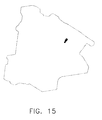
- Figures 6, 10, and 14 are point cloud images extracted from 3-D iamges of another sample of that part. This sample contains a flaw. When points less than a predetermined distance from any surface in the CAD drawing are removed, the remaining points, shown in Figures 7, 11, and 15, illustrate the flaw in the sample part.
- Figure 16 illustrates a method for creating a point cloud in two dimensions.
- the method can be extended in a third, perpendicular dimension to accommodate 3-D images, but is illustrated in 2-D for simplicity.
- a perpendicular grid 160 representing x and y directions (in 3-D, a z-direction is also used) is superimposed on an image 162 of a part, which in this example, is shown as an irregularly shaped image.
- the point cloud is determined as a set of points 164 that correspond to intersections of boundaries of contrasting regions 166, 168 with grid 160.
- Configurations of the present invention can be used to find anomalies in finished aircraft parts, including, but not limited to turbine blades. Although methods and apparatus disclosed herein are particularly suitable for aircraft parts, their uses are not limited to aircraft part and various configurations of the present invention can be used with other types of manufactured parts. It will be appreciated that configurations of the present invention can be used to produce high quality complex machined components and assemblies (i.e., parts).
Landscapes
- Engineering & Computer Science (AREA)
- Theoretical Computer Science (AREA)
- Health & Medical Sciences (AREA)
- Physics & Mathematics (AREA)
- General Physics & Mathematics (AREA)
- Pulmonology (AREA)
- Computer Vision & Pattern Recognition (AREA)
- Nuclear Medicine, Radiotherapy & Molecular Imaging (AREA)
- Quality & Reliability (AREA)
- Radiology & Medical Imaging (AREA)
- Life Sciences & Earth Sciences (AREA)
- Chemical & Material Sciences (AREA)
- Analytical Chemistry (AREA)
- Biochemistry (AREA)
- General Health & Medical Sciences (AREA)
- Immunology (AREA)
- Pathology (AREA)
- Analysing Materials By The Use Of Radiation (AREA)
Applications Claiming Priority (1)
| Application Number | Priority Date | Filing Date | Title |
|---|---|---|---|
| US11/328,878 US7602963B2 (en) | 2006-01-10 | 2006-01-10 | Method and apparatus for finding anomalies in finished parts and/or assemblies |
Publications (2)
| Publication Number | Publication Date |
|---|---|
| EP1808813A2 true EP1808813A2 (de) | 2007-07-18 |
| EP1808813A3 EP1808813A3 (de) | 2007-09-19 |
Family
ID=37907126
Family Applications (1)
| Application Number | Title | Priority Date | Filing Date |
|---|---|---|---|
| EP07100324A Ceased EP1808813A3 (de) | 2006-01-10 | 2007-01-10 | Verfahren und Vorrichtung zum Auffinden von Abweichungen an fertigen Bauteilen und/oder Anordnungen |
Country Status (4)
| Country | Link |
|---|---|
| US (1) | US7602963B2 (de) |
| EP (1) | EP1808813A3 (de) |
| JP (1) | JP5220316B2 (de) |
| SG (2) | SG154442A1 (de) |
Cited By (7)
| Publication number | Priority date | Publication date | Assignee | Title |
|---|---|---|---|---|
| DE102007060892A1 (de) * | 2007-12-14 | 2009-01-15 | Carl Zeiss Industrielle Messtechnik Gmbh | Auswertung eines durch Vermessung mittels invasiver Strahlung erhaltenen Messdatensatzes |
| WO2010046117A2 (de) | 2008-10-24 | 2010-04-29 | Fraunhofer-Gesellschaft zur Förderung der angewandten Forschung e.V | Verfahren und röntgencomputertomograf zur untersuchung eines objektes mittels röntgencomputertomografie |
| EP2226609A3 (de) * | 2009-01-30 | 2010-12-08 | General Electric Company | Zerstörungsfreie Prüfung einer Maschine auf bestimmte Defekte (Fremdkörper, anomale Abmessungen) z.B. mithilfe von Computertomografie |
| WO2012148520A2 (en) | 2011-02-11 | 2012-11-01 | Quality Vision International, Inc. | Tolerance evaluation with reduced measured points |
| CN103134823A (zh) * | 2013-03-21 | 2013-06-05 | 重庆大学 | 一种基于卷积的x射线ct系统射束硬化校正方法 |
| WO2016146703A1 (en) * | 2015-03-16 | 2016-09-22 | Katholieke Universiteit Leuven | Automated quality control and selection |
| CN107407646A (zh) * | 2015-03-03 | 2017-11-28 | 株式会社尼康 | 测量处理装置、x射线检查装置、测量处理方法、测量处理程序及结构物的制造方法 |
Families Citing this family (47)
| Publication number | Priority date | Publication date | Assignee | Title |
|---|---|---|---|---|
| CN101617197B (zh) * | 2007-02-16 | 2011-06-22 | 三菱电机株式会社 | 测量装置、测量方法及地物识别装置 |
| CN101377851A (zh) * | 2007-08-29 | 2009-03-04 | 鸿富锦精密工业(深圳)有限公司 | 点云到点云的最近距离计算系统及方法 |
| JP2009053151A (ja) * | 2007-08-29 | 2009-03-12 | Ihi Corp | X線検査方法 |
| US8010315B2 (en) * | 2007-11-27 | 2011-08-30 | General Electric Company | Multi-modality inspection method with data validation and data fusion |
| US7840367B2 (en) * | 2007-11-28 | 2010-11-23 | General Electric Company | Multi-modality inspection system |
| CN101587504A (zh) * | 2008-05-21 | 2009-11-25 | 鸿富锦精密工业(深圳)有限公司 | 自定义曲面检测报告系统及方法 |
| US9177371B2 (en) * | 2008-06-09 | 2015-11-03 | Siemens Energy, Inc. | Non-destructive examination data visualization and analysis |
| US8290719B2 (en) * | 2008-09-26 | 2012-10-16 | The Boeing Company | Mode identification and decomposition for ultrasonic signals |
| CN102142142A (zh) * | 2010-01-29 | 2011-08-03 | 鸿富锦精密工业(深圳)有限公司 | 产品轮廓制程能力验证系统及方法 |
| DE102010043226A1 (de) * | 2010-11-02 | 2012-05-03 | Fraunhofer-Gesellschaft zur Förderung der angewandten Forschung e.V. | Verfahren und Auswertungsvorrichtung zur Ermittlung der Lage einer in einem zu untersuchenden Objekt befindlichen Struktur mittels Röntgencomputertomografie |
| US8861673B2 (en) | 2011-11-30 | 2014-10-14 | United Technologies Corporation | Component aperture location using computed tomography |
| US8798372B1 (en) * | 2012-03-07 | 2014-08-05 | Hrl Laboratories, Llc | Method for detecting bridges using lidar point cloud data |
| CN103377297A (zh) * | 2012-04-24 | 2013-10-30 | 鸿富锦精密工业(深圳)有限公司 | 产品变形分析系统及方法 |
| US9410905B2 (en) | 2013-03-27 | 2016-08-09 | United Technologies Corporation | Non-destructive inspection of an article using cross-sections through internal feature |
| US20160189339A1 (en) * | 2013-04-30 | 2016-06-30 | Mantisvision Ltd. | Adaptive 3d registration |
| CN103955939B (zh) * | 2014-05-16 | 2018-06-19 | 重庆理工大学 | 三维扫描系统中点云拼接用边界特征点配准方法 |
| US10295475B2 (en) | 2014-09-05 | 2019-05-21 | Rolls-Royce Corporation | Inspection of machined holes |
| KR101616327B1 (ko) * | 2014-10-15 | 2016-04-28 | 삼성중공업 주식회사 | 3차원 점군 생성 시스템 및 방법 |
| CN104867136B (zh) * | 2015-05-06 | 2017-06-16 | 华中科技大学 | 一种基于距离方差最小的工件点云匹配算法 |
| US9618459B2 (en) | 2015-05-18 | 2017-04-11 | Flightware, Inc. | Systems and methods for automated composite layup quality assurance |
| US10668673B2 (en) | 2015-05-18 | 2020-06-02 | Flightware, Inc. | Systems and methods for automated composite layup quality assurance |
| US10228669B2 (en) | 2015-05-27 | 2019-03-12 | Rolls-Royce Corporation | Machine tool monitoring |
| US10025492B2 (en) * | 2016-02-08 | 2018-07-17 | Microsoft Technology Licensing, Llc | Pointing detection |
| US10943240B2 (en) | 2017-04-05 | 2021-03-09 | General Electric Company | Additively manufactured component including a contrast agent for part identification |
| US11090727B2 (en) | 2017-04-05 | 2021-08-17 | General Electric Company | Additively manufactured component having surface features for part identification |
| US10549347B2 (en) | 2017-04-05 | 2020-02-04 | General Electric Company | System and method for authenticating components |
| US10762407B2 (en) | 2017-04-05 | 2020-09-01 | General Electric Company | Component incorporating 3-D identification code |
| US10703086B2 (en) | 2017-04-05 | 2020-07-07 | General Electric Company | System and method for authenticating an additively manufactured component |
| US10706139B2 (en) | 2017-04-05 | 2020-07-07 | General Electric Company | System and method for authenticating components |
| AU2018286423B2 (en) | 2017-06-15 | 2022-10-27 | Drillscan France Sas | Generating drilling paths using a drill model |
| US10488371B1 (en) | 2018-05-04 | 2019-11-26 | United Technologies Corporation | Nondestructive inspection using thermoacoustic imagery and method therefor |
| US11268881B2 (en) | 2018-05-04 | 2022-03-08 | Raytheon Technologies Corporation | System and method for fan blade rotor disk and gear inspection |
| US10928362B2 (en) | 2018-05-04 | 2021-02-23 | Raytheon Technologies Corporation | Nondestructive inspection using dual pulse-echo ultrasonics and method therefor |
| US10473593B1 (en) | 2018-05-04 | 2019-11-12 | United Technologies Corporation | System and method for damage detection by cast shadows |
| US10685433B2 (en) | 2018-05-04 | 2020-06-16 | Raytheon Technologies Corporation | Nondestructive coating imperfection detection system and method therefor |
| US10943320B2 (en) | 2018-05-04 | 2021-03-09 | Raytheon Technologies Corporation | System and method for robotic inspection |
| US10902664B2 (en) | 2018-05-04 | 2021-01-26 | Raytheon Technologies Corporation | System and method for detecting damage using two-dimensional imagery and three-dimensional model |
| US10914191B2 (en) | 2018-05-04 | 2021-02-09 | Raytheon Technologies Corporation | System and method for in situ airfoil inspection |
| US11079285B2 (en) | 2018-05-04 | 2021-08-03 | Raytheon Technologies Corporation | Automated analysis of thermally-sensitive coating and method therefor |
| US10958843B2 (en) | 2018-05-04 | 2021-03-23 | Raytheon Technologies Corporation | Multi-camera system for simultaneous registration and zoomed imagery |
| CN109283936A (zh) * | 2018-08-15 | 2019-01-29 | 广州极飞科技有限公司 | 移动装置控制方法、装置及终端 |
| CN109685890A (zh) * | 2018-12-24 | 2019-04-26 | 厦门大学 | 一种空心涡轮叶片气膜冷却孔背壁损伤主动防护方法 |
| SG10202001721UA (en) | 2019-03-14 | 2020-10-29 | Gen Electric | Acoustic inspection device and method of operation |
| US11420259B2 (en) | 2019-11-06 | 2022-08-23 | General Electric Company | Mated components and method and system therefore |
| WO2022021151A1 (zh) * | 2020-07-29 | 2022-02-03 | 西门子(中国)有限公司 | 生产线装配组件的检查方法和装置 |
| CN112801977B (zh) * | 2021-01-28 | 2022-11-22 | 青岛理工大学 | 一种基于深度学习的装配体零件相对位姿估计监测方法 |
| WO2023248583A1 (ja) * | 2022-06-21 | 2023-12-28 | 富士フイルム株式会社 | 情報処理装置、情報処理方法、及び情報処理プログラム |
Citations (1)
| Publication number | Priority date | Publication date | Assignee | Title |
|---|---|---|---|---|
| EP0875751A1 (de) | 1997-05-02 | 1998-11-04 | General Electric Company | Computertomograph-Metrologie |
Family Cites Families (15)
| Publication number | Priority date | Publication date | Assignee | Title |
|---|---|---|---|---|
| US5111048A (en) | 1990-09-27 | 1992-05-05 | General Electric Company | Apparatus and method for detecting fatigue cracks using infrared thermography |
| US5345514A (en) | 1991-09-16 | 1994-09-06 | General Electric Company | Method for inspecting components having complex geometric shapes |
| US6041132A (en) | 1997-07-29 | 2000-03-21 | General Electric Company | Computed tomography inspection of composite ply structure |
| US6285449B1 (en) | 1999-06-11 | 2001-09-04 | University Of Chicago | Optical method and apparatus for detection of defects and microstructural changes in ceramics and ceramic coatings |
| US6683641B1 (en) | 1999-09-01 | 2004-01-27 | United Technologies Corporation | Apparatus for inspecting the interior of hollow articles |
| EP1337963A4 (de) * | 2000-10-30 | 2005-11-02 | Translation Technologies Inc | Rechen-geometriesystem, interrupt-schnittstelle, geometrischer modellkomparator und verfahren |
| JP4178854B2 (ja) * | 2002-07-08 | 2008-11-12 | トヨタ自動車株式会社 | 鋳造品内部欠陥検査支援装置及び方法 |
| US7149339B2 (en) | 2003-02-25 | 2006-12-12 | Schlumberger Technology Corporation | Non-destructive inspection of downhole equipment |
| US6968730B2 (en) | 2003-05-16 | 2005-11-29 | General Electric Company | Non-destructive evaluation of thermal barrier coatings in gas turbine engines |
| TWI310142B (en) * | 2003-05-28 | 2009-05-21 | Hon Hai Prec Ind Co Ltd | Cad-based cav system and method |
| JP4131400B2 (ja) * | 2003-08-01 | 2008-08-13 | トヨタ自動車株式会社 | 鋳造内部欠陥検査支援装置及び方法 |
| JP4144483B2 (ja) * | 2003-09-02 | 2008-09-03 | トヨタ自動車株式会社 | 鋳造内部欠陥検査支援装置および方法 |
| JP2005249426A (ja) * | 2004-03-01 | 2005-09-15 | Toyota Motor Corp | 鋳造内部欠陥検査支援装置及び方法 |
| US7095221B2 (en) | 2004-05-27 | 2006-08-22 | Siemens Aktiengesellschaft | Doppler radar sensing system for monitoring turbine generator components |
| JP4588414B2 (ja) * | 2004-10-28 | 2010-12-01 | 株式会社日立製作所 | 内部欠陥検査方法および装置 |
-
2006
- 2006-01-10 US US11/328,878 patent/US7602963B2/en not_active Expired - Fee Related
-
2007
- 2007-01-10 EP EP07100324A patent/EP1808813A3/de not_active Ceased
- 2007-01-10 SG SG200904477-7A patent/SG154442A1/en unknown
- 2007-01-10 JP JP2007001979A patent/JP5220316B2/ja not_active Expired - Fee Related
- 2007-01-10 SG SG200700149-8A patent/SG134240A1/en unknown
Patent Citations (1)
| Publication number | Priority date | Publication date | Assignee | Title |
|---|---|---|---|---|
| EP0875751A1 (de) | 1997-05-02 | 1998-11-04 | General Electric Company | Computertomograph-Metrologie |
Non-Patent Citations (1)
| Title |
|---|
| SCHILLINGER B: "Proposed combination of CAD data and discrete tomography for the detection of coking and lubricants in turbine blades or engines", ELECTRONIC NOTES IN DISCRETE MATHEMATICS, NORTH-HOLLAND LNKD- DOI:10.1016/J.ENDM.2005.05.081, vol. 20, 1 July 2005 (2005-07-01), pages 493 - 499, XP004943910, ISSN: 1571-0653 * |
Cited By (17)
| Publication number | Priority date | Publication date | Assignee | Title |
|---|---|---|---|---|
| DE102007060892A1 (de) * | 2007-12-14 | 2009-01-15 | Carl Zeiss Industrielle Messtechnik Gmbh | Auswertung eines durch Vermessung mittels invasiver Strahlung erhaltenen Messdatensatzes |
| WO2010046117A2 (de) | 2008-10-24 | 2010-04-29 | Fraunhofer-Gesellschaft zur Förderung der angewandten Forschung e.V | Verfahren und röntgencomputertomograf zur untersuchung eines objektes mittels röntgencomputertomografie |
| WO2010046117A3 (de) * | 2008-10-24 | 2014-09-12 | Fraunhofer-Gesellschaft zur Förderung der angewandten Forschung e.V | Polychromatische reprojektion eines fehlerbereinigten tomogramms und anschliessende rekonstruktion zur erzeugung eines nur fehler aufgrund der strahlungsaufhartung enthaltenden referenztomogramms |
| EP2226609A3 (de) * | 2009-01-30 | 2010-12-08 | General Electric Company | Zerstörungsfreie Prüfung einer Maschine auf bestimmte Defekte (Fremdkörper, anomale Abmessungen) z.B. mithilfe von Computertomografie |
| EP2824415A1 (de) | 2011-02-11 | 2015-01-14 | Quality Vision International Inc. | Toleranzbewertung mit weniger gemessenen Punkten |
| WO2012148520A2 (en) | 2011-02-11 | 2012-11-01 | Quality Vision International, Inc. | Tolerance evaluation with reduced measured points |
| EP2673589A4 (de) * | 2011-02-11 | 2013-12-18 | Quality Vision Internat Inc | Toleranzbewertung mit weniger gemessenen punkten |
| EP2673589A2 (de) * | 2011-02-11 | 2013-12-18 | Quality Vision International Inc. | Toleranzbewertung mit weniger gemessenen punkten |
| CN103134823A (zh) * | 2013-03-21 | 2013-06-05 | 重庆大学 | 一种基于卷积的x射线ct系统射束硬化校正方法 |
| CN103134823B (zh) * | 2013-03-21 | 2015-03-11 | 重庆大学 | 一种基于卷积的x射线ct系统射束硬化校正方法 |
| CN107407646A (zh) * | 2015-03-03 | 2017-11-28 | 株式会社尼康 | 测量处理装置、x射线检查装置、测量处理方法、测量处理程序及结构物的制造方法 |
| US20180120243A1 (en) | 2015-03-03 | 2018-05-03 | Nikon Corporation | Measurement processing device, x-ray inspection device, measurement processing method, measurement processing program, and structure manufacturing method |
| EP3267183A4 (de) * | 2015-03-03 | 2019-04-17 | Nikon Corporation | Messungsverarbeitungsvorrichtung, röntgeninspektionsverfahren, messungsverarbeitungsverfahren, messungsverarbeitungsprogramm und strukturherstellungsverfahren |
| US10481106B2 (en) | 2015-03-03 | 2019-11-19 | Nikon Corporation | Measurement processing device, X-ray inspection device, measurement processing method, measurement processing program, and structure manufacturing method |
| US10809209B2 (en) | 2015-03-03 | 2020-10-20 | Nikon Corporation | Measurement processing device, x-ray inspection device, measurement processing method, measurement processing program, and structure manufacturing method |
| WO2016146703A1 (en) * | 2015-03-16 | 2016-09-22 | Katholieke Universiteit Leuven | Automated quality control and selection |
| US10520452B2 (en) | 2015-03-16 | 2019-12-31 | Katholieke Universiteit Leuven | Automated quality control and selection |
Also Published As
| Publication number | Publication date |
|---|---|
| US7602963B2 (en) | 2009-10-13 |
| JP5220316B2 (ja) | 2013-06-26 |
| JP2007192818A (ja) | 2007-08-02 |
| EP1808813A3 (de) | 2007-09-19 |
| SG154442A1 (en) | 2009-08-28 |
| US20070160282A1 (en) | 2007-07-12 |
| SG134240A1 (en) | 2007-08-29 |
Similar Documents
| Publication | Publication Date | Title |
|---|---|---|
| US7602963B2 (en) | Method and apparatus for finding anomalies in finished parts and/or assemblies | |
| EP2226609A2 (de) | Zerstörungsfreie Prüfung einer Maschine auf bestimmte Defekte (Fremdkörper, anomale Abmessungen) z.B. mithilfe von Computertomografie | |
| Kruth et al. | Computed tomography for dimensional metrology | |
| US8010315B2 (en) | Multi-modality inspection method with data validation and data fusion | |
| CN108226290B (zh) | 一种基于超声相控阵的零件内部缺陷三维参数提取方法 | |
| JP4588414B2 (ja) | 内部欠陥検査方法および装置 | |
| US20200051229A1 (en) | Method for the non-destructive testing of the volume of a test object and testing device configured for carrying out such a method | |
| CN109477804B (zh) | 设置方法、检查方法、缺陷评估装置及结构体的制造方法 | |
| Senck et al. | Additive manufacturing and non-destructive testing of topology-optimised aluminium components | |
| Buratti et al. | Applications of CT for dimensional metrology | |
| EP1793226A2 (de) | Verfahren und Systeme für Ultraschallprüfungen | |
| US7092484B1 (en) | Model-assisted reconstruction of volumetric data | |
| CN113888531A (zh) | 混凝土表面缺陷检测方法、装置、电子设备及存储介质 | |
| Du Plessis | X‐ray tomography for the advancement of laser powder bed fusion additive manufacturing | |
| JP2005249426A (ja) | 鋳造内部欠陥検査支援装置及び方法 | |
| De Amicis et al. | Morphology-based macro-scale finite-element timber models | |
| Jin et al. | Scale and pose-invariant feature quality inspection for freeform geometries in additive manufacturing | |
| Hastie et al. | Computed Tomography Wall Thickness Inspection to Support Gas Turbine Blade Life Extension | |
| EP3722793A2 (de) | Verfahren zur prüfung von bauteilen mittels computertomographie | |
| Zhang et al. | Classification of internal defects of gas turbine blades based on the discrimination of linear attenuation coefficients | |
| Chahid | Metrology of Additive Manufactured Lattice Structures | |
| Shao et al. | Compressor Blade Fault Diagnosis Based on Image Processing | |
| du Plessis et al. | X-ray micro-CT supporting the South African Additive Manufacturing Community | |
| Devaraj | Accuracy asessment of a computed tomography based reverse engineering | |
| Neel et al. | X-Ray Computed Tomography Application Research |
Legal Events
| Date | Code | Title | Description |
|---|---|---|---|
| PUAI | Public reference made under article 153(3) epc to a published international application that has entered the european phase |
Free format text: ORIGINAL CODE: 0009012 |
|
| AK | Designated contracting states |
Kind code of ref document: A2 Designated state(s): AT BE BG CH CY CZ DE DK EE ES FI FR GB GR HU IE IS IT LI LT LU LV MC NL PL PT RO SE SI SK TR |
|
| AX | Request for extension of the european patent |
Extension state: AL BA HR MK YU |
|
| PUAL | Search report despatched |
Free format text: ORIGINAL CODE: 0009013 |
|
| AK | Designated contracting states |
Kind code of ref document: A3 Designated state(s): AT BE BG CH CY CZ DE DK EE ES FI FR GB GR HU IE IS IT LI LT LU LV MC NL PL PT RO SE SI SK TR |
|
| AX | Request for extension of the european patent |
Extension state: AL BA HR MK YU |
|
| 17P | Request for examination filed |
Effective date: 20080319 |
|
| 17Q | First examination report despatched |
Effective date: 20080429 |
|
| AKX | Designation fees paid |
Designated state(s): DE FR GB IT |
|
| STAA | Information on the status of an ep patent application or granted ep patent |
Free format text: STATUS: THE APPLICATION HAS BEEN REFUSED |
|
| 18R | Application refused |
Effective date: 20101028 |