EP1807154B1 - Reduction of discomfort using nerve stimulation - Google Patents
Reduction of discomfort using nerve stimulation Download PDFInfo
- Publication number
- EP1807154B1 EP1807154B1 EP05819902.7A EP05819902A EP1807154B1 EP 1807154 B1 EP1807154 B1 EP 1807154B1 EP 05819902 A EP05819902 A EP 05819902A EP 1807154 B1 EP1807154 B1 EP 1807154B1
- Authority
- EP
- European Patent Office
- Prior art keywords
- stimulation
- magnetic
- magnetic stimulation
- magnetic field
- nerve
- Prior art date
- Legal status (The legal status is an assumption and is not a legal conclusion. Google has not performed a legal analysis and makes no representation as to the accuracy of the status listed.)
- Expired - Lifetime
Links
Images


Classifications
-
- A—HUMAN NECESSITIES
- A61—MEDICAL OR VETERINARY SCIENCE; HYGIENE
- A61N—ELECTROTHERAPY; MAGNETOTHERAPY; RADIATION THERAPY; ULTRASOUND THERAPY
- A61N2/00—Magnetotherapy
- A61N2/004—Magnetotherapy specially adapted for a specific therapy
- A61N2/006—Magnetotherapy specially adapted for a specific therapy for magnetic stimulation of nerve tissue
-
- A—HUMAN NECESSITIES
- A61—MEDICAL OR VETERINARY SCIENCE; HYGIENE
- A61N—ELECTROTHERAPY; MAGNETOTHERAPY; RADIATION THERAPY; ULTRASOUND THERAPY
- A61N2/00—Magnetotherapy
- A61N2/004—Magnetotherapy specially adapted for a specific therapy
- A61N2/008—Magnetotherapy specially adapted for a specific therapy for pain treatment or analgesia
Definitions
- the invention relates to the field of transcutaneous stimulation. Specifically, the invention relates to using magnetic fields to reduce discomfort.
- a number of medical ailments are treated or treatable through the application of electrical stimulation to an afflicted portion of a patient's body.
- Neurons, muscle and tissue cells are all forms of biological tissue capable of carrying electrical signals and responding to electrical stimuli.
- Two examples of electrical stimulation may include magnetic or inductive stimulation which may make use of a changing magnetic field, and electric or capacitive stimulation in which an electric field may be applied to the tissue.
- an electric field is induced causing current to flow in the conductor.
- various parts of the body are also conductive, when a changing magnetic field is applied to the portion of the body, an electric field is created in the conductive tissue, thereby causing current to flow.
- the resultant flow of electric current can stimulate the tissue by causing neurons in the tissue to depolarize.
- muscles for example, muscles associated with the stimulated neurons contract.
- Magnetic stimulation has many beneficial and therapeutic biological effects.
- magnetic stimulation is effective in rehabilitating injured or paralyzed muscle groups.
- Magnetic stimulation is also proving effective for treatment of the spine, which is difficult to access directly because vertebrae surround it.
- Magnetic stimulation may be used to block the transmission of pain via nerves in the back (e.g ., the nerves responsible for lower back pain) or via other nerves in other locations.
- magnetic field stimulation may be non-invasive. For example, using magnetic fields to generate current in the body produces stimulation by passing the magnetic field through the skin of a patient.
- conventional electric stimulation pain treatment methods for lower back pain involve the placement of electrodes in the spinal cord to enable stimulation.
- a needle may be inserted proximate the problematic nerve to enable electric stimulation.
- Magnetic stimulation also has proven effective in stimulating regions of the brain.
- One area of particular therapeutic interest is the treatment of neuropsychiatric disorders. It is believed that more than 28 million people in the United States alone suffer from some type of neuropsychiatric disorder. These include specific conditions such as depression, schizophrenia, mania, obsessive-compulsive disorder, panic disorders, just to name a few.
- One particular condition, depression is believed to affect 19 million people in the United States alone, and possibly 340 million people worldwide.
- Modem medicine offers depression patients a number of treatment options, including several classes of anti-depressant medications such as selective serotonin reuptake inhibitors (SSRIs), MAIs, tricyclics, lithium, and electroconvulsive therapy (ECT). Yet many patients remain without satisfactory relief from the symptoms of depression. To date, ECT remains an effective treatment for major depressive disorder; however, many patients will not undergo the procedure because of its severe side effects.
- SSRIs selective serotonin reuptake inhibitors
- MAIs tricyclics
- rTMS repetitive transcranial magnetic stimulation
- a subconvulsive stimulation is applied to the prefrontal cortex in a repetitive manner, causing a depolarization of cortical neurons.
- the neurons are depolarized by the induction of an electric field, usually in excess of one volt per centimeter (V/cm). These electric fields result from a rapidly changing magnetic field applied non-invasively.
- rTMS prefrontal cortex regions of the brain have strong communication links to Limbic System structures, which contain the "circuits" controlling mood and general behavior.
- One objective of rTMS is to provide stimulation to these biological circuits through a non-invasive, subconvulsive technique to relieve the symptoms of depression without many of the negative side effects of ECT or medications.
- one reported side effect of rTMS for the treatment of depression is patient discomfort at the site of the stimulation. It should be appreciated that discomfort may also be present in other forms of magnetic stimulation to other areas of the body.
- a patient may experience discomfort at locations other than the head area, such as at peripheral nerves and the like. Such locations may be at any location and at any depth within a patient's body. In such cases, it would be advantageous to reduce discomfort regardless of where the discomfort-causing nerve is located. Accordingly, it is desirable to develop techniques for reducing discomfort, whether caused by electrical stimulation or by other causes. In addition, it is desirable to develop techniques to more accurately stimulate a desired region of a patient while minimizing stimulation of surrounding tissue.
- WO 2004/080527 A2 discloses a method for reducing discomfort caused by transcutaneous stimulation in which field interference is used for this purpose.
- the magnetic flux density decreases in strength as the square of the distance from the source of the magnetic field, the flux density is greater the closer the conductor is to the source of the magnetic field.
- the conductor is a coil
- the current induced in the coil by the electric field may be increased in proportion to the number of turns of the coil and the area of the coil.
- the electric field When an electric field is induced in a conductor, the electric field creates a corresponding current flow in the conductor.
- the current flow is in the same direction of the electric field vector at a given point.
- the peak electric field occurs when dB / dt is the greatest and diminishes at other times. If the electric field decreases, for example after a magnetic pulse, the current flows in a direction that tends to preserve the electric field (i.e., Lenz's Law).
- certain parts of the anatomy e.g ., nerves, tissue, muscle, brain
- the electric field may be presented to these parts of the anatomy transcutaneously by applying a time varying (e.g ., pulsed) magnetic field to the portion of the body.
- a time varying magnetic field may be applied across the skull to create an electric field in the brain tissue, which produces a current. If the induced current is of sufficient density, neuron action potential may be reduced to the extent that the membrane sodium channels open and an action potential response is created.
- An impulse of current is then propagated along the axon membrane that transmits information to other neurons via modulation of neurotransmitters.
- Such magnetic stimulation has been shown to acutely affect glucose metabolism and local blood flow in cortical tissue.
- neurotransmitter dysregulation and abnormal glucose metabolism in the prefrontal cortex and the connected limbic structures may be a likely pathophysiology.
- Repeated application of magnetic stimulation to the prefrontal cortex may produce chronic changes in neurotransmitter concentrations and metabolism so that depression is alleviated.
- non-cortical neurons e.g ., cranial nerves, peripheral nerves, sensory nerves
- cranial nerves e.g ., cranial nerves, peripheral nerves, sensory nerves
- an induced electric field e.g ., cranial nerves, peripheral nerves, sensory nerves
- Techniques have been developed to intentionally stimulate peripheral nerves to diagnose neuropathologies by observing response times and conduction velocities in response to a pulsed magnetic field induced stimulus. Discomfort and/or pain may result if the induced electric field applied to a peripheral or cranial nerve is very intense or focused on a small area of such a nerve. This discomfort may be diminished by intentionally over-stimulating the sensory nerves in the affected nerve bundle so that they can no longer respond to external pain stimuli, or by reducing the intensity and focus of the induced electric field that is causing the pain sensation.
- transcutaneous magnetic stimulation is not limited to treatment of depression.
- the transcutaneous magnetic stimulation methods and apparatus described herein may be used to treat a patient such as a human suffering from epilepsy, schizophrenia, Parkinson's disease, Tourette's syndrome, amyotrophic lateral sclerosis (ALS), multiple sclerosis (MS), Alzheimer's disease, attention deficit/hyperactivity disorder, obesity, bipolar disorder/mania, anxiety disorders (e.g ., panic disorder with and without agoraphobia, social phobia also known as social anxiety disorder, acute stress disorder and generalized anxiety disorder), post-traumatic stress disorder (one of the anxiety disorders in DSM), obsessive compulsive disorder (also one of the anxiety disorders in DSM), pain (such as, for example, migraine and trigeminal neuralgia, as well as chronic pain disorders, including neuropathic pain, e.g ., pain due to diabetic neuropathy, post-herpetic neuralgia, and idiopathic pain disorders, e.
- a patient such as a human suffering from
- transcranial magnetic stimulation techniques For purposes of explanation and clarity, the discussion herein focuses primarily on the treatment of discomfort caused by transcranial magnetic stimulation techniques as well as discomfort reduction in peripheral nerves. It will be appreciated that the present disclosure is equally applicable to any type of discomfort, and can be used to treat nerves at any location within a patient's body. In addition, the disclosure may be employed in connection with any type of transcutaneous magnetic stimulation, and is in no way limited to transcranial applications.
- a ferromagnetic core may be used to produce a magnetic field for purposes of carrying out transcutaneous magnetic stimulation such as, for example, Transcranial Magnetic Stimulation (TMS), Repetitive TMS (rTMS), Magnetic Seizure Therapy (MST), reduction of peripheral nerve discomfort and so forth.
- transcutaneous magnetic stimulation such as, for example, Transcranial Magnetic Stimulation (TMS), Repetitive TMS (rTMS), Magnetic Seizure Therapy (MST), reduction of peripheral nerve discomfort and so forth.
- TMS Transcranial Magnetic Stimulation
- rTMS Repetitive TMS
- MST Magnetic Seizure Therapy
- a ferromagnetic core may be approximately hemispherical, and in another embodiment the ferromagnetic core may include a highly saturable magnetic material having a magnetic saturation of at least 0.5 Tesla.
- a ferromagnetic core may be shaped to optimize the magnetic field distribution in the treatment area. Treatment areas for other forms of treatment (e.g ., reduction of discomfort in peripheral nerves, etc. ) may be more or less deep that is the case for TMS.
- the ferromagnetic core permits efficient localization of the generated magnetic field. Effectively targeting a treatment location can reduce discomfort by either appropriately treating a problematic nerve, or by treating a treatment area without also undesirably stimulating neighboring nerves.
- a typical ferromagnetic core coil for TMS applications is designed to produce a magnetic field that exceeds the cortical stimulation threshold over a 2-3 cm region near the surface of the brain. It will be appreciated that the magnetic field further diminishes at points deeper in the cortex.
- a deeper anatomical structure such as a cranial nerve passing through a foramen in the skull
- This concentration effect can elevate the local current density above the neuron stimulation threshold in the focal areas of highest conductivity. If the structure is a sensory nerve (e.g. , trigeminal bundle) it could be stimulated even though it is located outside the region where the magnetic field exceeds the cortical stimulation threshold.
- an embodiment of the present disclosure uses additional coils in conjunction with the TMS coil that are designed and placed in such a way that the magnetic fields superimpose with the primary TMS coil field and reduce the induced electric field and current near the affected nerve without reducing the primary magnetic field in the region of therapy.
- the field produced by such a secondary coil can be lower than that of the primary TMS coil because it is physically placed near the affected nerve and it only needs to serve to diminish the induced current density at the site of nerve stimulation.
- the secondary coil or coils may also serve to reduce discomfort through other means such as over-stimulating the affected nerve so that it can not respond to further stimulation caused by the TMS field.
- Fig. 1 illustrates a ferromagnetic core material magnetic stimulation device 10, or "coil,” that may be used in connection with an embodiment of the invention.
- Device 10 comprises ferromagnetic core 12 surrounded by windings 14.
- An insulative material 16 is interposed between core 12 and windings 14.
- Device 10 also includes cable 20 for connecting device 10 to a control system (not shown in Fig. 1 for clarity). Cable 20 may be covered by housing 18 for protection and strain relief.
- a ferromagnetic core 12 can be fabricated from various ferromagnetic materials such as, for example, 3% grain oriented silicon steel or vanadium permendur (also known as supermendur).
- the material is chosen to have, for example, a high saturation level, a sharp-knee B-H curve (i.e., quickly switches from saturated to non-saturated states), low eddy current losses, and a practical cost.
- the core material may be fabricated into many electrically isolated layers to minimize eddy current losses.
- the orientation of the lamination may be such as to disrupt the eddy currents (i.e., perpendicular to the direction of induced current flow whenever possible). Also, if the material has a grain orientation, it should be directed parallel to the induced magnetic flux.
- the ferromagnetic core is according to U.S. Patent Nos. 6,132,361 and 5,725,471 , each of which is hereby incorporated by reference in their entireties.
- patient treatment typically includes applying a magnetic field to the patient using a coil constructed with an approximately hemispherical ferromagnetic core.
- the strength of the field and switching rate is sufficient to produce stimulation of the target area in a manner that is appropriate to the type of treatment being administered.
- transcutaneous stimulation may be used to reduce patient discomfort by directly applying a magnetic field to a problematic nerve such as, for example, a peripheral nerve.
- a problematic nerve such as, for example, a peripheral nerve.
- the transcutaneous stimulation of a patient while therapeutic, may have undesirable side effects.
- cranial nerves, trigeminal nerves, etc. may experience magnetic fields that are above their respective stimulation thresholds.
- a patient may experience discomfort from, for example, muscle twitching, pain from sensory nerves, etc.
- it is advantageous to target the magnetic field so as to lower the magnetic field at areas that are not to be treated, i.e., at non-treatment area locations.
- discomfort may be reduced in any number of contexts.
- discomfort may be treated directly, by applying magnetic stimulation to the affected nerve to numb, over-stimulate or otherwise treat the nerve to mitigate the discomfort.
- the magnetic field applied to the nerve may be modified in terms of field strength, pulse repetition rate, vector orientation, frequency characteristics, or the like to achieve a desired effect.
- Another way to mitigate discomfort is, as noted above, to reduce adverse collateral stimulation that results from magnetic stimulation of tissue in proximity to the treatment area.
- the methods used to reduce adverse collateral stimulation may be the same or different than the methods used to treat a discomfort-causing nerve. In either context, it can be seen that effective targeting of a therapeutic magnetic field can be used to reduce patient discomfort.
- branches of the trigeminal nerve located on the left and right sides of the skull
- branches of the trigeminal nerve may sometimes be particularly troublesome with respect to unwanted stimulation.
- some branches of the trigeminal nerve are located deeper within the tissue of the skull and penetrate the skull through small openings (foramina) and extend to areas of the face.
- the large difference in conductivity between the bone and the nerve penetrating a foramen the current density is increased at the foramen.
- the trigeminal nerve and its branches may be exposed to a higher level of magnetic stimulation that may be above the nerve's stimulation threshold resulting in, for example, facial muscle contractions and/or pain during transcranial magnetic stimulation. Therefore, the magnetic field used to treat a patient should not only be above a stimulation threshold at a treatment location, but should also be locally minimized in sensitive adjacent tissue, such as the trigeminal nerve, to reduce discomfort. Thus, a method for reducing a magnetic field, for example in the region of the trigeminal foramina, to sub-stimulation levels would be advantageous.
- FIG. 2 is a diagram illustrating a passive technique for reducing discomfort caused by transcutaneous stimulation.
- system 200 includes one or more ferrite pads 210 located above a patient's head 202 and under magnetic stimulation device 201. It should be appreciated that the physical configuration of ferrite pads 210 are illustrated for the purpose of discussion and clarity, and is not meant to be an exclusive representation of such a configuration. For example, ferrite pads 210 may be located between magnetic stimulation device 201 and the patient's head 202.
- ferrite pads 210 may be attached directly and/or indirectly to the patient's head 202 and/or directly or indirectly connected to magnetic stimulation device 201. In a non-transcranial embodiment, ferrite pads 210 may be placed, for example, between magnetic stimulation device 201 and any location proximate a treatment area. In addition, the number and placement of ferrite pads 210 are not limited to any particular configuration, and may be used in conjunction with any of the other methods described herein.
- Ferrite pads 210 operate to effectively "absorb" the magnetic field (lines 204a-e) created by magnetic stimulation device 201.
- ferrite pads 210 may be designed and constructed to offset, reduce and/or absorb magnetic field (lines 204a-e) that stimulate the surface-proximate tissue, while permitting magnetic field that penetrates deeper into the patient for therapeutic purposes to pass substantially unaffected.
- ferrite pads 210 typically have low conductivity and therefore do not encourage induced eddy currents and associated heating or temporal disruption of the therapeutic magnetic field created by magnetic stimulation device 201. It should be appreciated that although system 200 has been described in the context of ferrite material, the pads also may be made of other non-ferrite material and/or a combination of ferrite material and non-ferrite materials.
- the ferrite pads 210 are "passive," in that they are not driven by a power source. Rather, the ferrite pads 210 mitigate unwanted stimulation by their mere physical presence.
- the ferrite pads 210 while effective for mitigating unwanted surface stimulation, are not as effective at mitigating unwanted stimulation at depth because they can only passively absorb the magnetic field (lines 204a-e) created by magnetic stimulation device 210.
- ferrite pads 210 can only be configured physically ( e.g ., size, location, shape, etc.), rather than electrically, so the pads 210 are unable to create a magnetic field that can interact, either constructively or destructively, with that of magnetic stimulation device 201.
- Fig. 3 is a diagram illustrating an active technique for reducing discomfort caused by transcutaneous stimulation.
- system 300 includes power supply 301 in communication with electrodes 302a and 302b. Although two electrodes 302a-b are shown in Fig. 3 , it should be appreciated that any number of electrodes may be used.
- magnetic stimulation device 201 creates a pulsed magnetic field (lines 205a-d), which in turn creates an electric field (lines 204a-e).
- Electric field (204a-e) induces both desirable and undesirable electric currents on and within the patient's head 202.
- System 300 overcomes the discomfort created by the undesired electric currents at surface-proximate locations, while also permitting the desired electric currents to continue to have their therapeutic effect on the patient at a location deeper within the patient's body.
- power supply 301 provides power (i.e., current and/or voltage) to electrodes 302, which conduct the power from power supply 301 to the patient's head 202.
- the electrodes may therefore actively reduce discomfort by providing substantially constant or time-varying power to electrodes 302.
- the power conducted to the patient's head 202 via electrodes 302 creates a substantially constant electric field in the nerves, muscle and tissues of the patient that lie in between or proximate to electrodes 302.
- the electric field created by electrodes 302 may have a strength that biases certain cells (i.e., those that are undesirably stimulated by magnetic stimulation device 201).
- the bias level may be such that the cells are biased near or above their depolarization level. By biasing the cells at or near their depolarization level, electrolytes for example, are redistributed along the cell, thus reducing the ability of the electrolytes to be transported across the cell membrane.
- Reducing transport of the electrolytes across the cell membrane reduces the possible stimulation of those cells by magnetic stimulation device 201, because the cells may not be as capable of repeatedly responding to the induced electric field created by magnetic stimulation device 201. As a result, the discomfort felt by the patient during treatment is reduced.
- this example was discussed in the context of a substantially constant power source, it should be appreciated that the power need not be applied throughout the entire treatment, but may for example be turned off at any point after the beginning of a pulse corresponding to the therapeutic magnetic stimulation.
- power provided by power source 301 may be time-varying.
- the time-varying signal from power source 301 may be used to desensitize the muscle, tissue and/or nerves that undesirably are stimulated by magnetic stimulation device 201.
- power source 301 may be designed to pre-stimulate (i.e., prior to the therapeutic pulse applied by magnetic stimulation device 201) particular nerves, muscle and/or tissue to reduce their ability to undesirably respond to the otherwise therapeutic pulse. Because electrodes 302 are necessarily placed superficially, this method does not address mitigation of undesired deeper nerve stimulation
- system 400 includes magnetic stimulation device 402 that receives power from stimulation circuit 403 to create magnetic fields (not shown in Fig. 4A for clarity) in the patient's head 406.
- magnetic stimulation device 402 creates a pulsed magnetic field that induces current within the patient for certain beneficial therapeutic effects, such as the treatment of depression using TMS, for example.
- the same magnetic field may create discomfort for the patient by undesirably inducing current into surface-proximate tissue, nerves and muscle.
- Surface coil 401 located at or near the patient 406 (and possibly between the patient and magnetic stimulation device 402), may be used to offset, eliminate or reduce the undesired effects of the magnetic field created by magnetic stimulation device 402.
- Pulse programmer 405 generates an appropriate waveform
- drive circuit 404 receive the waveform generated by pulse programmer 405 and provides power to the surface coil 401.
- surface coil 401 may generate its own magnetic field that cancels the portion of the magnetic field created by magnetic stimulation device 402 that acts to undesirably stimulate surface-proximate tissue, nerves and muscle.
- the strength and disposition of the magnetic field created by surface coil 401 may be such that the therapeutic strength of the primary magnetic field created by magnetic stimulation device 402 remains substantially undiminished in the region of therapy.
- Fig. 4B is a diagram illustrating a detail view of coil 401 in one embodiment.
- coil 401 is coupled to a mounting pad 407, which may be fabricated from any substance that does not substantially interfere with the operation of coil 401.
- Mounting pad 407 may, in one embodiment, have an adhesive backing or other fastening means for permitting the mounting pad to be located on a patient's head ( e.g ., patient 406, not shown in Fig. 4B for clarity).
- contacts 408a-b are present to enable coupling of the coil 401 to a power source, such as drive circuit 404 discussed above in connection with Fig. 4A (not shown in Fig. 4B for clarity).
- the superficial configuration of surface coil 401 limits its ability to mitigate deeper, unwanted stimulation without adversely affecting the magnetic field in the therapeutic region.
- an embodiment of the present disclosure provides a plurality of magnetic stimulation devices, or “coils” (e.g., a device having a core such as, for example, a ferromagnetic core material magnetic stimulation device 10 as discussed above in connection with Fig. 1 ) to enable therapeutic transcutaneous magnetic stimulation while reducing discomfort.
- An embodiment of the present disclosure uses two or more of such magnetic coils to reduce discomfort without adversely affecting the intended therapy.
- one embodiment uses a larger first magnetic coil (magnetic stimulation device) to create a relatively unfocused, first magnetic field of sub-stimulation threshold strength throughout an area of a patient in which a treatment area is located (e.g., a patient's head).
- a smaller, second coil is used to create a relatively focused, second magnetic field of sub-stimulation strength.
- the magnetic fields may be configured to add (i.e., through superposition) at the treatment area, thereby generating a focused magnetic field that is above a stimulation threshold in the treatment area, thereby enabling therapeutic treatment while minimizing stimulation of the surrounding tissue and reducing discomfort.
- the treatment itself may be directed to reduction of discomfort, in addition to the reduction of discomfort that results from the reduction in stimulation to tissue surrounding the treatment area.
- the larger coil is able to produce a magnetic field that may penetrate deep within a patient, if desired, while the smaller coil produces a focused magnetic field so as to accurately target the treatment area.
- the advantages of each size of magnetic coil are exploited, while the shortcomings of each size of coil are mitigated because the large coil is not required to produce a tightly focused magnetic field, and the smaller coil is not required to generate the full strength of a hyperstimulation threshold magnetic field.
- any number, size and/or configuration of coils may be employed in such an embodiment to create a focused magnetic field at one or more treatment areas.
- Such a configuration may be able to reach treatment locations deep within a patient with a tailored magnetic field to treat discomfort and the like without causing additional or ancillary discomfort in surrounding tissue.
- non-treatment areas of the patient can be exposed to even lower magnetic fields than would otherwise be possible with a single magnetic coil.
- one or more larger, first magnetic coils may be used to generate a magnetic field that is above a stimulation threshold for a treatment area.
- One or more smaller, second magnetic coils may be used to generate one or more focused magnetic fields to target a discomfort-causing nerve.
- the magnetic fields may be configured to cancel each other to the point where the combined magnetic field at the discomfort-causing nerve is below a stimulation threshold, thereby reducing discomfort while not substantially affecting stimulation in the treatment area.
- the one or more smaller, second magnetic coils may target a discomfort-causing area of stimulation for purposes of intentionally over-stimulating the nerve so the nerve is effectively numbed and cannot respond to the magnetic field.
- an over-stimulation technique may be used at the treatment area itself to reduce discomfort. It will be appreciated that the use of a magnetic coil to perform such cancellation or over-stimulation enables the reduction of discomfort-causing nerve stimulation at locations deep within a patient's body.
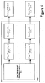
- Fig. 5 is a block diagram illustrating a technique for performing transcutaneous stimulation using more than one ferromagnetic core coils.
- Stimulation system 510 controls the operation of the coils by providing a desired amount of power to the coils while pulsing the coils in an appropriate manner. The waveform shape, frequency, etc., may be chosen according to the patient and/or type of treatment being performed.
- User interface and stimulator control 511 permits a user of stimulation system 510 to enter one or more desired parameters for the operation of the coils. It will be appreciated that any number and/or type of parameters may be entered for purposes of controlling the coils.
- User interface and stimulator control 511 may be configured in a similar manner to a controller used for the discomfort-reducing techniques discussed above, although it will be appreciated that control 511 may be adapted to control more than one magnetic stimulation coil.
- Pulse programmers 512A-B generate the appropriate waveform, according to the parameters received by the user interface and stimulator control 511, for input into each of the drive circuits 513A-B. In one embodiment, additional parameters may automatically be included in the waveform generation process.
- Drive circuits 513A-B receive the waveforms generated by pulse programmers 512A-B and provide power to the primary and secondary coils 501A-B, respectively.
- primary pulse programmer A 512A may generate a waveform that will result in a magnetic field having different properties than the magnetic field resulting from a waveform generated by secondary pulse programmer B 512B. So long as the magnetic fields have the desired characteristics at the treatment area, any configuration of magnetic fields may be used.
- Primary coil 501A generates the primary magnetic field in a manner that was explained above in connection with Fig. 1 .
- primary coil 501A may provide the main therapeutic magnetic field, or it may be configured to provide a smaller portion of the therapeutic magnetic field.
- secondary coil 501B provides a magnetic field that may be the same as the magnetic field provided by primary coil 501A, or secondary coil 501B may provide a magnetic field having different characteristics from the field generated by primary coil 501A.
- each coil 501A-B may be physically identical, or may have different mechanical and/or electromagnetic characteristics.
- primary coil 501A is used to generate a sub-stimulation level magnetic field and secondary coil 501B adds another sub-stimulation level magnetic field to the treatment area.
- neither magnetic field alone may be above the stimulation threshold for either the treatment area or for other areas of the patient, such as the cranial nerves, trigeminal nerves, etc.
- the levels and locations of both sub-stimulation level magnetic fields may be chosen such that the fields add to each other at the desired treatment location, as was discussed above.
- the combined magnetic field may be of sufficient strength to stimulate the area by depolarizing neurons at the treatment location.
- Figs. 6A and 6B are diagrams illustrating an exemplary configuration of multiple magnetic stimulation devices (e.g ., multiple ferromagnetic core magnetic stimulation devices) used to perform transcutaneous stimulation. It can be seen that Fig. 6A is a frontal view of a patient 1001, while Fig. 6B is a perspective view of patient 1001. Primary coil 501A and secondary coil 501B are as described above in connection with Fig. 5 . A patient's head 1001 is shown, and treatment area 1000 is illustrated at an arbitrary location within the patient's head 1001. It will be appreciated that the configuration of Fig. 6A may be adapted to provide a therapeutic magnetic field to a treatment area that is at any location on the patient, and is not limited to patient's head 1001.
- multiple magnetic stimulation devices e.g ., multiple ferromagnetic core magnetic stimulation devices
- primary coil 501A may be the "main" coil that provides the majority of the therapeutic magnetic field, while secondary coil 501B may provide a localized magnetic field to create a magnetic field at treatment area 1000 that is above a stimulation threshold.
- primary coil 501A may produce a sub-stimulation level magnetic field for all points within the skull.
- the smaller, secondary coil 501B may be pulsed in synchrony with the primary coil to produce a magnetic field that is localized so as to target the treatment area 1001.
- the sum of the fields from coils 501A and B may be above the stimulation threshold in treatment area 1000 and may rapidly fall off to sub-stimulation levels outside the target region, thus exposing cranial nerves, and particularly trigeminal nerves, to a sub-stimulation level magnetic field.
- the coils 501A and B may be designed so that the magnetic field at the trigeminal nerve (particularly at the foramina) is sufficiently reduced so no sensation is felt by patient 1001, for example. It will be appreciated that while treating other nerves in other locations within a body, the coil configuration discussed above may be able to treat patient discomfort in peripheral nerves even when such nerves are deep within the patient's body.
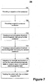
- Fig. 7 is a flowchart illustrating the use of multiple magnetic stimulation devices to perform transcutaneous stimulation.
- the illustrated method 700 facilitates transcutaneous magnetic stimulation treatments while minimizing patient discomfort.
- a signal may be provided to a first conductor. It will be appreciated that, in an embodiment, the signal may be generated by primary drive circuit 513A described above in connection with Fig. 5 , and is sent to the first conductor, which may be part of primary coil 501A.
- a signal is provided to a second conductor. It will be appreciated that, in an embodiment, the signal is generated by secondary drive circuit 513B and may be sent to the second conductor, which is part of secondary coil 501B.
- a sub-stimulation threshold electric and/or magnetic field is created using the first conductor.
- primary coil 501A is pulsed to create a magnetic field as was described above in connection with Figs. 6A-B . It may be appreciated that this magnetic field may be a relatively unfocused field, as was also discussed above.
- another sub-stimulation threshold electric and/or magnetic field may be created using the second conductor. Again, it may be appreciated that this field may be a relatively focused field as was also discussed above.
- secondary coil 501B may be pulsed to create a magnetic field as was also described above in connection with Figs. 6A-B .
- step 705 the strength and location, and possibly other parameters, of the magnetic fields generated by the conductors are adjusted to create a region of combined electric and/or magnetic field. It will be appreciated that adjustments might not be necessary in step 705 if the electric and/or magnetic fields were correctly configured initially.
- the patient is treated with the combined magnetic field in connection with transcutaneous magnetic stimulation treatment such as, for example, TMS, rTMS or the like.
- transcutaneous magnetic stimulation treatment such as, for example, TMS, rTMS or the like.
- a plurality of coils may be configured in any number of ways while still remaining consistent with the present disclosure.
- a configuration in accordance with one embodiment uses a first coil (e.g., the primary coil 501A) in a conventional TMS fashion, where the first coil provides sufficient field strength for the desired TMS stimulation.
- a second coil e.g., the secondary coil 501B
- an embodiment may be configured to either cause the second coil to cancel some or all of the magnetic field in the region of the cranial nerve that is causing the patient discomfort (referred to as “localized field cancellation"), or the second coil may be used to intentionally over-stimulate the cranial nerve so the nerve is numbed and is therefore unable to respond to the pulses from the first coil (referred to as "over-stimulation").
- Localized field cancellation using the second coil may be very important in certain applications where sensation from the first coil is particularly acute.
- One such application is, for example, the use of TMS for treatment of schizophrenia ( i.e., auditory hallucinations).
- the target region is near superficial musculature and trigeminal nerve branches.
- the second coil may be empirically placed to minimize sensations during such a procedure. It will be appreciated that the orientation of the second coil with respect to the first coil in this particular embodiment should cause the fields to cancel.
- the second coil is operated with a pulse waveform whose frequency is optimized to couple with the cranial nerve. It is repeatedly pulsed at a rate sufficient to guarantee that the nerve cannot repolarize and respond to external stimulus. Pulsing of the second coil is not necessarily synchronized with the primary TMS treatment. In an embodiment the two coils may be oriented so their fields do not add in the event that both coils were to be pulsed simultaneously. Alternatively, the second coil may be sequenced such that it will not be pulsed when a primary TMS treatment pulse is applied.
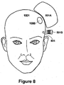
- Fig. 8 is a block diagram illustrating an exemplary configuration of multiple magnetic stimulation devices used to reduce discomfort caused by transcutaneous stimulation. It will be appreciated that the configuration of Fig. 8 may be used in either context described above; that is, either for localized field cancellation and/or for over-stimulation. In addition, the configuration of Fig. 8 is described in connection with transcranial treatment for purposes of explanation and clarity, as the configuration may be used in connection with any treatment method, including the methods listed above.
- primary coil 501 A provides a primary, therapeutic magnetic field that is sufficient for the desired stimulation at treatment area 1000 within a patient's head 1001.
- Secondary coil 501B provides a second magnetic field that is directed to cranial nerve 801.
- cranial nerve 801 can be any type of cranial nerve or nerves in any region of patient's head 1001 that is causing as a result of the stimulation treatment.
- the magnetic field provided by secondary coil 501B may either provide for localized field cancellation by canceling a part of the primary magnetic field, or for over-stimulation by ensuring that cranial nerve 801 cannot repolarize during the transcranial magnetic stimulation procedure.
- Fig. 9 is a flowchart illustrating the use of multiple magnetic stimulation devices to reduce discomfort caused by transcutaneous stimulation.
- the method 900 illustrated in Fig. 9 applies equally to localized field cancellation and to over-stimulation for reducing discomfort during any type of transcranial magnetic stimulation such as, for example, TMS, rTMS or other treatments.
- a signal is provided to a first conductor (e.g ., primary coil 501A) to create a primary electric and/or magnetic field that may be both above the stimulation threshold and sufficient for treatment purposes at the treatment area.
- primary coil 501A is pulsed to create a magnetic field as was described above in connection with Fig. 11.
- a signal is provided to a second conductor (e.g ., secondary coil 501B) to create a secondary electric and/or magnetic field.
- secondary coil 501A is pulsed to create a magnetic field as was described above in connection with Fig. 11.
- the strength and location, and possibly other parameters, of the magnetic field generated by the first conductor is adjusted to provide a therapeutic magnetic field at the treatment area.
- the method 900 the first conductor generates the full, therapeutic magnetic field on its own. It will also be appreciated that adjustments might not be necessary in step 903 if the electric and/or magnetic fields were correctly configured initially.
- the strength and location, and possibly other parameters, of the magnetic field generated by the second conductor are adjusted.
- the second conductor may provide a localized magnetic field that will sufficiently cancel the magnetic field created by the first conductor at a region associated with a discomfort-causing nerve or other tissue the stimulation of which causes patient discomfort or is otherwise undesired. In such a manner, the magnetic field experienced by the nerve is below its stimulation threshold.
- the second conductor provides a magnetic field that over-stimulates the discomfort-causing nerve so as to prevent the nerve from repolarizing during the treatment.
- method 900 and method 700 of Fig. 7 may be combined.
- a therapeutic magnetic field may be created by more than one primary coil according to method 700 of Fig. 7 .
- one or more other coils may be operated according to method 900 to reduce discomfort caused by the magnetic fields created by the primary coils. The methods of reducing discomfort may therefore be combined in any number of configurations.
- unmyelinated neurons i.e., neurons that are not covered by a myelin sheath, such as cortical neurons
- myelinated neurons i.e., different chronaxies or response time constants.
- the second coil may be "tuned" for the myelinated cranial nerve and may therefore be less effective in stimulating cortical neurons.
- the first coil may operate at a pulse frequency that best stimulates unmyelinated neurons, thereby minimizing unwanted stimulation of cranial nerves. It will be appreciated that such "tuning" may be employed in connection with any technique, or combination of techniques, described herein.
Landscapes
- Health & Medical Sciences (AREA)
- Engineering & Computer Science (AREA)
- Biomedical Technology (AREA)
- Neurology (AREA)
- Nuclear Medicine, Radiotherapy & Molecular Imaging (AREA)
- Radiology & Medical Imaging (AREA)
- Life Sciences & Earth Sciences (AREA)
- Animal Behavior & Ethology (AREA)
- General Health & Medical Sciences (AREA)
- Public Health (AREA)
- Veterinary Medicine (AREA)
- Magnetic Treatment Devices (AREA)
- Electrotherapy Devices (AREA)
Applications Claiming Priority (2)
| Application Number | Priority Date | Filing Date | Title |
|---|---|---|---|
| US10/977,734 US7857746B2 (en) | 2004-10-29 | 2004-10-29 | System and method to reduce discomfort using nerve stimulation |
| PCT/US2005/039298 WO2006050279A2 (en) | 2004-10-29 | 2005-10-28 | System and method to reduce discomfort using nerve stimulation |
Publications (3)
| Publication Number | Publication Date |
|---|---|
| EP1807154A2 EP1807154A2 (en) | 2007-07-18 |
| EP1807154A4 EP1807154A4 (en) | 2013-01-09 |
| EP1807154B1 true EP1807154B1 (en) | 2016-09-28 |
Family
ID=36262969
Family Applications (1)
| Application Number | Title | Priority Date | Filing Date |
|---|---|---|---|
| EP05819902.7A Expired - Lifetime EP1807154B1 (en) | 2004-10-29 | 2005-10-28 | Reduction of discomfort using nerve stimulation |
Country Status (8)
| Country | Link |
|---|---|
| US (1) | US7857746B2 (enExample) |
| EP (1) | EP1807154B1 (enExample) |
| JP (3) | JP2008518677A (enExample) |
| AU (1) | AU2005302300B2 (enExample) |
| CA (1) | CA2585842C (enExample) |
| DK (1) | DK1807154T3 (enExample) |
| ES (1) | ES2606665T3 (enExample) |
| WO (1) | WO2006050279A2 (enExample) |
Families Citing this family (74)
| Publication number | Priority date | Publication date | Assignee | Title |
|---|---|---|---|---|
| US7493171B1 (en) * | 2000-11-21 | 2009-02-17 | Boston Scientific Neuromodulation Corp. | Treatment of pathologic craving and aversion syndromes and eating disorders by electrical brain stimulation and/or drug infusion |
| US8047979B2 (en) | 2001-04-20 | 2011-11-01 | Mclean Hospital Corporation | Magnetic field treatment techniques |
| US8052591B2 (en) * | 2006-05-05 | 2011-11-08 | The Board Of Trustees Of The Leland Stanford Junior University | Trajectory-based deep-brain stereotactic transcranial magnetic stimulation |
| US7976451B2 (en) | 2005-06-16 | 2011-07-12 | The United States Of America As Represented By The Department Of Health And Human Services | Transcranial magnetic stimulation system and methods |
| US9352167B2 (en) | 2006-05-05 | 2016-05-31 | Rio Grande Neurosciences, Inc. | Enhanced spatial summation for deep-brain transcranial magnetic stimulation |
| US8267850B2 (en) | 2007-11-27 | 2012-09-18 | Cervel Neurotech, Inc. | Transcranial magnet stimulation of deep brain targets |
| JP4961558B2 (ja) * | 2007-03-30 | 2012-06-27 | 国立大学法人信州大学 | 三叉神経固有知覚枝刺激装置 |
| JP5037230B2 (ja) * | 2007-06-05 | 2012-09-26 | 国立大学法人北海道大学 | 脳機能リハビリテーション装置 |
| US20100185042A1 (en) * | 2007-08-05 | 2010-07-22 | Schneider M Bret | Control and coordination of transcranial magnetic stimulation electromagnets for modulation of deep brain targets |
| US8956274B2 (en) * | 2007-08-05 | 2015-02-17 | Cervel Neurotech, Inc. | Transcranial magnetic stimulation field shaping |
| US20100256439A1 (en) * | 2007-08-13 | 2010-10-07 | Schneider M Bret | Gantry and switches for position-based triggering of tms pulses in moving coils |
| CA2694037A1 (en) * | 2007-08-20 | 2009-02-20 | Neostim, Inc. | Firing patterns for deep brain transcranial magnetic stimulation |
| WO2009033192A1 (en) * | 2007-09-09 | 2009-03-12 | Neostim, Inc. | Focused magnetic fields |
| WO2009042718A1 (en) | 2007-09-25 | 2009-04-02 | Neosync, Inc. | Systems and methods for controlling and billing neuro-eeg synchronization therapy |
| US8265910B2 (en) * | 2007-10-09 | 2012-09-11 | Cervel Neurotech, Inc. | Display of modeled magnetic fields |
| US20100298623A1 (en) * | 2007-10-24 | 2010-11-25 | Mishelevich David J | Intra-session control of transcranial magnetic stimulation |
| US20100286468A1 (en) * | 2007-10-26 | 2010-11-11 | David J Mishelevich | Transcranial magnetic stimulation with protection of magnet-adjacent structures |
| AU2009259904A1 (en) * | 2008-06-20 | 2009-12-23 | Medrelief Inc. | Systems, apparatuses, and methods for providing non-transcranial electrotherapy |
| US8926490B2 (en) | 2008-09-24 | 2015-01-06 | Neosync, Inc. | Systems and methods for depression treatment using neuro-EEG synchronization therapy |
| US8795148B2 (en) * | 2009-10-26 | 2014-08-05 | Cervel Neurotech, Inc. | Sub-motor-threshold stimulation of deep brain targets using transcranial magnetic stimulation |
| US9180305B2 (en) * | 2008-12-11 | 2015-11-10 | Yeda Research & Development Co. Ltd. At The Weizmann Institute Of Science | Systems and methods for controlling electric field pulse parameters using transcranial magnetic stimulation |
| BRPI0918700B8 (pt) * | 2008-12-30 | 2021-06-22 | Univ City New York Res Found | conjuntos de eletrodo e aparelhos para a estimulação neurocraniana |
| WO2010080879A2 (en) | 2009-01-07 | 2010-07-15 | Neostim, Inc. | Shaped coils for transcranial magnetic stimulation |
| US8465408B2 (en) | 2009-08-06 | 2013-06-18 | Neosync, Inc. | Systems and methods for modulating the electrical activity of a brain using neuro-EEG synchronization therapy |
| EP4094689A1 (en) | 2009-11-12 | 2022-11-30 | Neosync, INC. | Systems and methods for neuro-eeg syncronization |
| US8321012B2 (en) | 2009-12-22 | 2012-11-27 | The Invention Science Fund I, Llc | Device, method, and system for neural modulation as vaccine adjuvant in a vertebrate subject |
| US9492679B2 (en) | 2010-07-16 | 2016-11-15 | Rio Grande Neurosciences, Inc. | Transcranial magnetic stimulation for altering susceptibility of tissue to pharmaceuticals and radiation |
| US10342987B2 (en) * | 2011-04-28 | 2019-07-09 | Osaka University | Therapeutic electromagnetic stimulation device and method of generating custom data pairs used in said device |
| US9649502B2 (en) | 2011-11-14 | 2017-05-16 | Neosync, Inc. | Devices and methods of low frequency magnetic stimulation therapy |
| DE102012013534B3 (de) | 2012-07-05 | 2013-09-19 | Tobias Sokolowski | Vorrichtung für repetitive Nervenstimulation zum Abbau von Fettgewebe mittels induktiver Magnetfelder |
| JP6189439B2 (ja) | 2012-07-30 | 2017-08-30 | ニューロプレックス インコーポレイテッド | 神経障害の治療用の磁気刺激のための装置および方法 |
| US9682248B2 (en) | 2012-09-20 | 2017-06-20 | University Of Rochester | Deep brain magnetic stimulator |
| US9254394B2 (en) | 2013-02-21 | 2016-02-09 | Brainsway, Ltd. | Central base coils for deep transcranial magnetic stimulation |
| US9533168B2 (en) | 2013-02-21 | 2017-01-03 | Brainsway, Ltd. | Unilateral coils for deep transcranial magnetic stimulation |
| US9248308B2 (en) * | 2013-02-21 | 2016-02-02 | Brainsway, Ltd. | Circular coils for deep transcranial magnetic stimulation |
| US9808642B2 (en) * | 2013-02-21 | 2017-11-07 | Brainsway, Ltd. | Circular coils for deep transcranial magnetic stimulation |
| US11730970B2 (en) | 2013-03-14 | 2023-08-22 | The Methodist Hospital | Method and apparatus for providing transcranial magnetic stimulation (TMS) to an individual |
| US9456784B2 (en) | 2013-03-14 | 2016-10-04 | The Methodist Hospital | Method and apparatus for providing transcranial magnetic stimulation (TMS) to a patient |
| ES2755998T3 (es) | 2013-08-15 | 2020-04-24 | Methodist Hospital | Aparato para proporcionar estimulación magnética transcraneal (EMT) a un individuo |
| US9849301B2 (en) * | 2014-01-15 | 2017-12-26 | Neuronetics, Inc. | Magnetic stimulation coils and ferromagnetic components for reduced surface stimulation and improved treatment depth |
| US10232187B2 (en) | 2014-02-14 | 2019-03-19 | Osaka University | Coil device and transcranial magnetic stimulation system |
| JP2017526162A (ja) * | 2014-06-02 | 2017-09-07 | モナシュ、ユニバーシティMonash University | 集中磁場を発生させるための磁気回路 |
| US10588576B2 (en) | 2014-08-15 | 2020-03-17 | Neosync, Inc. | Methods and device for determining a valid intrinsic frequency |
| WO2016104578A1 (ja) | 2014-12-25 | 2016-06-30 | 帝人ファーマ株式会社 | 磁気刺激装置 |
| AU2016240919B2 (en) * | 2015-04-02 | 2020-05-14 | Osaka University | Coil apparatus for use in transcranial magnetic stimulation apparatus |
| US11491342B2 (en) | 2015-07-01 | 2022-11-08 | Btl Medical Solutions A.S. | Magnetic stimulation methods and devices for therapeutic treatments |
| US20180001107A1 (en) | 2016-07-01 | 2018-01-04 | Btl Holdings Limited | Aesthetic method of biological structure treatment by magnetic field |
| US10695575B1 (en) | 2016-05-10 | 2020-06-30 | Btl Medical Technologies S.R.O. | Aesthetic method of biological structure treatment by magnetic field |
| CN107921252A (zh) | 2015-07-06 | 2018-04-17 | 特斯拉医疗公司 | 电刺激装置 |
| IL243686B (en) | 2016-01-19 | 2022-05-01 | Epitech Mag Ltd | Device for increasing the integrity of the eye epithelium using magnetic pulses |
| US10307607B2 (en) * | 2016-02-09 | 2019-06-04 | Palo Alto Research Center Incorporated | Focused magnetic stimulation for modulation of nerve circuits |
| US11247039B2 (en) | 2016-05-03 | 2022-02-15 | Btl Healthcare Technologies A.S. | Device including RF source of energy and vacuum system |
| US11464993B2 (en) | 2016-05-03 | 2022-10-11 | Btl Healthcare Technologies A.S. | Device including RF source of energy and vacuum system |
| US10874870B2 (en) | 2016-05-05 | 2020-12-29 | The Methodist Hospital | Method and apparatus for providing transcranial magnetic stimulation (TMS) to an individual |
| US11534619B2 (en) | 2016-05-10 | 2022-12-27 | Btl Medical Solutions A.S. | Aesthetic method of biological structure treatment by magnetic field |
| US10583287B2 (en) | 2016-05-23 | 2020-03-10 | Btl Medical Technologies S.R.O. | Systems and methods for tissue treatment |
| US10556122B1 (en) | 2016-07-01 | 2020-02-11 | Btl Medical Technologies S.R.O. | Aesthetic method of biological structure treatment by magnetic field |
| US11141219B1 (en) | 2016-08-16 | 2021-10-12 | BTL Healthcare Technologies, a.s. | Self-operating belt |
| US10806942B2 (en) | 2016-11-10 | 2020-10-20 | Qoravita LLC | System and method for applying a low frequency magnetic field to biological tissues |
| JP1602547S (enExample) | 2017-01-17 | 2018-04-23 | ||
| IL253677B2 (en) | 2017-07-26 | 2023-06-01 | Epitech Mag Ltd | A magnetic device for the treatment of living tissues |
| CA3090358A1 (en) * | 2018-02-05 | 2019-08-08 | Brainsway Ltd. | Electromagnetic coil assembly |
| DK3755422T3 (da) * | 2018-02-20 | 2025-06-30 | Neuronetics Inc | Magnetiske stimulationsspoler og ferromagnetiske komponenter til behandlingsprocedurer og diagnostiske procedurer |
| US11000693B2 (en) | 2018-02-20 | 2021-05-11 | Neuronetics, Inc. | Magnetic stimulation coils and ferromagnetic components for treatment and diagnostic procedures |
| CN110354393A (zh) * | 2018-03-26 | 2019-10-22 | 郑云峰 | 中枢神经磁刺激装置 |
| US12186575B2 (en) | 2018-11-13 | 2025-01-07 | The Methodist Hospital | Method and apparatus for oncomagnetic treatment |
| PL4066887T3 (pl) | 2019-04-11 | 2024-03-04 | Btl Medical Solutions A.S. | Urządzenia do zabiegu estetycznego struktur biologicznych za pomocą energii o częstotliwości radiowej i energii magnetycznej |
| US12156689B2 (en) | 2019-04-11 | 2024-12-03 | Btl Medical Solutions A.S. | Methods and devices for aesthetic treatment of biological structures by radiofrequency and magnetic energy |
| EP4146335B1 (en) | 2020-05-04 | 2024-11-13 | BTL Healthcare Technologies a.s. | Device for unattended treatment of a patient |
| US11878167B2 (en) | 2020-05-04 | 2024-01-23 | Btl Healthcare Technologies A.S. | Device and method for unattended treatment of a patient |
| EP4168108A4 (en) | 2020-06-19 | 2024-07-17 | The Methodist Hospital dba Houston Methodist Hospital | METHOD AND APPARATUS FOR ONCOMAGNETIC TREATMENT |
| WO2023062563A1 (en) | 2021-10-13 | 2023-04-20 | Btl Medical Solutions A.S. | Devices for aesthetic treatment of biological structures by radiofrequency and magnetic energy |
| US11896816B2 (en) | 2021-11-03 | 2024-02-13 | Btl Healthcare Technologies A.S. | Device and method for unattended treatment of a patient |
| CN118787862B (zh) * | 2024-09-10 | 2025-02-18 | 南昌大学附属康复医院(南昌大学第四附属医院) | 低频正弦磁神经调控装置及相关产品 |
Family Cites Families (123)
| Publication number | Priority date | Publication date | Assignee | Title |
|---|---|---|---|---|
| US3658051A (en) | 1967-11-13 | 1972-04-25 | Kenneth Sheldon Maclean | Method of treating living things using high intensity pulsed magnetic field |
| US3683923A (en) | 1970-09-25 | 1972-08-15 | Valleylab Inc | Electrosurgery safety circuit |
| US4638798A (en) | 1980-09-10 | 1987-01-27 | Shelden C Hunter | Stereotactic method and apparatus for locating and treating or removing lesions |
| US4473074A (en) | 1981-09-28 | 1984-09-25 | Xanar, Inc. | Microsurgical laser device |
| US4601753A (en) | 1983-05-05 | 1986-07-22 | General Electric Company | Powdered iron core magnetic devices |
| GB8406509D0 (en) | 1984-03-13 | 1984-04-18 | Bio Medical Res Ltd | Electrical stimulation of muscle |
| US5047005A (en) | 1987-01-28 | 1991-09-10 | Cadwell Industries, Inc. | Method and apparatus for magnetically stimulating neurons |
| US5116304A (en) | 1987-01-28 | 1992-05-26 | Cadwell Industries, Inc. | Magnetic stimulator with skullcap-shaped coil |
| US4940453A (en) | 1987-01-28 | 1990-07-10 | Cadwell Industries, Inc. | Method and apparatus for magnetically stimulating neurons |
| US4994015A (en) | 1987-09-14 | 1991-02-19 | Cadwell Industries, Inc. | Magnetic stimulator coils |
| DE3804491A1 (de) | 1987-12-02 | 1989-06-15 | Olympus Optical Co | Vorrichtung fuer die gehirnchirurgie |
| GB8728150D0 (en) | 1987-12-02 | 1988-01-06 | Inst Of Neurology Queen Square | Head fixation apparatus |
| FI83266C (fi) | 1988-09-12 | 1991-06-10 | Teknillinen Korkeakoulu | Foerfarande och anordning foer lokalisering av elektroder faestade vid kroppen av en maenniska, i synnerhet huvudet. |
| US5078674A (en) | 1989-02-10 | 1992-01-07 | Cadwll Industries, Inc. | Magnetic stimulator coils |
| US5097833A (en) | 1989-09-19 | 1992-03-24 | Campos James M | Transcutaneous electrical nerve and/or muscle stimulator |
| US5061234A (en) | 1989-09-25 | 1991-10-29 | Corteks, Inc. | Magnetic neural stimulator for neurophysiology |
| US5299569A (en) | 1991-05-03 | 1994-04-05 | Cyberonics, Inc. | Treatment of neuropsychiatric disorders by nerve stimulation |
| JP2892181B2 (ja) * | 1991-05-31 | 1999-05-17 | 照剛 上野 | 磁気刺激コイル |
| US5254123A (en) | 1992-02-24 | 1993-10-19 | Complete System Diagnostics, Inc. | Compressive device for ultrasound-guided repair of pseudoaneurysms |
| US6117066A (en) | 1992-12-04 | 2000-09-12 | Somatics, Inc. | Prevention of seizure arising from medical magnetoictal non-convulsive stimulation therapy |
| US5813970A (en) | 1992-12-04 | 1998-09-29 | Somatics, Inc. | Medical magnetoictal therapy |
| WO1994028815A1 (en) | 1993-06-15 | 1994-12-22 | Mitaka Kohki Co., Ltd. | Stand for optical device |
| US5769778A (en) | 1994-04-22 | 1998-06-23 | Somatics, Inc. | Medical magnetic non-convulsive stimulation therapy |
| US5725471A (en) | 1994-11-28 | 1998-03-10 | Neotonus, Inc. | Magnetic nerve stimulator for exciting peripheral nerves |
| US6086525A (en) | 1994-11-28 | 2000-07-11 | Neotonus, Inc. | Magnetic nerve stimulator for exciting peripheral nerves |
| US6425852B1 (en) | 1994-11-28 | 2002-07-30 | Emory University | Apparatus and method for transcranial magnetic brain stimulation, including the treatment of depression and the localization and characterization of speech arrest |
| US6132361A (en) * | 1994-11-28 | 2000-10-17 | Neotonus, Inc. | Transcranial brain stimulation |
| WO1998006342A1 (en) * | 1996-08-15 | 1998-02-19 | Neotonus, Inc. | Transcranial brain stimulation |
| US6618614B1 (en) | 1995-01-03 | 2003-09-09 | Non-Invasive Technology, Inc. | Optical examination device, system and method |
| GB9504216D0 (en) | 1995-03-02 | 1995-04-19 | Magstim Co Ltd | Magnetic stimulator for neuro-muscular tissue |
| US5566681A (en) | 1995-05-02 | 1996-10-22 | Manwaring; Kim H. | Apparatus and method for stabilizing a body part |
| WO1997000639A2 (en) | 1995-06-19 | 1997-01-09 | Holcomb Robert R | Electromagnetic treatment device and methods of using |
| WO1997000649A1 (en) | 1995-06-20 | 1997-01-09 | Wan Sing Ng | Articulated arm for medical procedures |
| US5707334A (en) | 1995-08-21 | 1998-01-13 | Young; Robert B. | Method of treating amygdala related transitory disorders |
| US6480743B1 (en) | 2000-04-05 | 2002-11-12 | Neuropace, Inc. | System and method for adaptive brain stimulation |
| US6463328B1 (en) | 1996-02-02 | 2002-10-08 | Michael Sasha John | Adaptive brain stimulation method and system |
| CN1224367A (zh) | 1996-04-26 | 1999-07-28 | 乌尔姆大学生物医学工程研究中心 | 聚焦的磁神经刺激及检测的方法和设备 |
| FI964387A0 (fi) | 1996-10-30 | 1996-10-30 | Risto Ilmoniemi | Foerfarande och anordning foer kartlaeggning av kontakter inom hjaernbarken |
| EP0850665B1 (en) | 1996-12-27 | 2004-03-03 | Nihon Kohden Corporation | Magnetic stimulus type urinary incontinence treatment coil apparatus |
| US6057373A (en) | 1997-05-22 | 2000-05-02 | Synchroneuron, Llc | Methods of treating tardive dyskinesia and other movement disorders using NMDA receptor antagonists |
| WO1999020339A1 (en) | 1997-10-17 | 1999-04-29 | Respironics, Inc. | Muscle stimulating device and method for diagnosing and treating a breathing disorder |
| US6597954B1 (en) | 1997-10-27 | 2003-07-22 | Neuropace, Inc. | System and method for controlling epileptic seizures with spatially separated detection and stimulation electrodes |
| FI103384B1 (fi) | 1997-11-28 | 1999-06-30 | Risto Ilmoniemi | Stimulointikärki ja menetelmä stimulaattorikelan äänen vaimentamiseksi |
| US6074385A (en) | 1998-02-03 | 2000-06-13 | Kiefer Corp. | Hair follicle devitalization by induced heating of magnetically susceptible particles |
| US6179771B1 (en) | 1998-04-21 | 2001-01-30 | Siemens Aktiengesellschaft | Coil arrangement for transcranial magnetic stimulation |
| GB9808764D0 (en) | 1998-04-25 | 1998-06-24 | Magstim Co Ltd | Magnetic stimulators for neuro-muscular tissue |
| US6266556B1 (en) | 1998-04-27 | 2001-07-24 | Beth Israel Deaconess Medical Center, Inc. | Method and apparatus for recording an electroencephalogram during transcranial magnetic stimulation |
| US6169963B1 (en) | 1998-06-02 | 2001-01-02 | Magnetherapy, Inc. | Magnetic field strength mapping system |
| AUPP398898A0 (en) | 1998-06-09 | 1998-07-02 | University Of Queensland, The | Diagnostic method and apparatus |
| US6198958B1 (en) | 1998-06-11 | 2001-03-06 | Beth Israel Deaconess Medical Center, Inc. | Method and apparatus for monitoring a magnetic resonance image during transcranial magnetic stimulation |
| EP0966988A1 (en) * | 1998-06-24 | 1999-12-29 | Santi Tofani | Apparatus and method for interfering with pathological cells survival |
| US6389318B1 (en) | 1998-07-06 | 2002-05-14 | Abiomed, Inc. | Magnetic shield for primary coil of transcutaneous energy transfer device |
| FI105163B (fi) | 1998-07-10 | 2000-06-30 | Juha Virtanen | Menetelmä ja laite lumemagneettistimulaation tuottamiseksi |
| US6210317B1 (en) | 1998-07-13 | 2001-04-03 | Dean R. Bonlie | Treatment using oriented unidirectional DC magnetic field |
| US7277758B2 (en) | 1998-08-05 | 2007-10-02 | Neurovista Corporation | Methods and systems for predicting future symptomatology in a patient suffering from a neurological or psychiatric disorder |
| US6279579B1 (en) | 1998-10-23 | 2001-08-28 | Varian Medical Systems, Inc. | Method and system for positioning patients for medical treatment procedures |
| US6366814B1 (en) | 1998-10-26 | 2002-04-02 | Birinder R. Boveja | External stimulator for adjunct (add-on) treatment for neurological, neuropsychiatric, and urological disorders |
| US6253109B1 (en) | 1998-11-05 | 2001-06-26 | Medtronic Inc. | System for optimized brain stimulation |
| US6155966A (en) | 1998-11-17 | 2000-12-05 | Parker; Lloyd S. | Apparatus and method for toning tissue with a focused, coherent electromagnetic field |
| US6477410B1 (en) | 2000-05-31 | 2002-11-05 | Biophoretic Therapeutic Systems, Llc | Electrokinetic delivery of medicaments |
| AU4505599A (en) | 1999-06-02 | 2000-12-28 | Medinova Medical Consulting Gmbh | Transcranial magnetic stimulation (tms) for improving vision in humans |
| WO2001012236A2 (en) | 1999-08-18 | 2001-02-22 | The General Hospital Corporation | Methods, compositions and kits for promoting recovery from damage to the central nervous system |
| US6567702B1 (en) | 1999-10-15 | 2003-05-20 | The Board Of Trustees Of The Leland Stanford Junior University | Eliciting analgesia by transcranial electrical stimulation |
| AU1213401A (en) | 1999-10-19 | 2001-04-30 | Johns Hopkins University, The | Techniques using heat flow management, stimulation, and signal analysis to treatmedical disorders |
| GB9926621D0 (en) | 1999-11-11 | 2000-01-12 | Magstim Co Ltd | Stimulating coil |
| US6516288B2 (en) | 1999-12-22 | 2003-02-04 | Curtis A. Bagne | Method and system to construct action coordination profiles |
| JP2001293098A (ja) | 2000-04-14 | 2001-10-23 | Nippon Koden Corp | コイル装置およびコイル駆動装置 |
| US6413263B1 (en) | 2000-04-24 | 2002-07-02 | Axon Instruments, Inc. | Stereotactic probe holder and method of use |
| WO2001097906A2 (en) | 2000-06-20 | 2001-12-27 | Advanced Bionics Corporation | Apparatus for treatment of mood and/or anxiety disorders by electrical brain stimulation and/or drug infusion |
| US7756584B2 (en) | 2000-07-13 | 2010-07-13 | Advanced Neuromodulation Systems, Inc. | Methods and apparatus for effectuating a lasting change in a neural-function of a patient |
| US7010351B2 (en) | 2000-07-13 | 2006-03-07 | Northstar Neuroscience, Inc. | Methods and apparatus for effectuating a lasting change in a neural-function of a patient |
| US20030125786A1 (en) | 2000-07-13 | 2003-07-03 | Gliner Bradford Evan | Methods and apparatus for effectuating a lasting change in a neural-function of a patient |
| US7831305B2 (en) | 2001-10-15 | 2010-11-09 | Advanced Neuromodulation Systems, Inc. | Neural stimulation system and method responsive to collateral neural activity |
| US7146217B2 (en) | 2000-07-13 | 2006-12-05 | Northstar Neuroscience, Inc. | Methods and apparatus for effectuating a change in a neural-function of a patient |
| US6497648B1 (en) | 2000-07-18 | 2002-12-24 | Omar Vicente Rey | Device for applying electromagnetic therapy |
| US6402678B1 (en) | 2000-07-31 | 2002-06-11 | Neuralieve, Inc. | Means and method for the treatment of migraine headaches |
| US6591138B1 (en) | 2000-08-31 | 2003-07-08 | Neuropace, Inc. | Low frequency neurostimulator for the treatment of neurological disorders |
| US6560490B2 (en) | 2000-09-26 | 2003-05-06 | Case Western Reserve University | Waveforms for selective stimulation of central nervous system neurons |
| CA2425871A1 (en) | 2000-10-10 | 2002-04-18 | Curtis A. Bagne | Method and system to construct action coordination profiles |
| US6488617B1 (en) | 2000-10-13 | 2002-12-03 | Universal Hedonics | Method and device for producing a desired brain state |
| JP2004511314A (ja) | 2000-10-20 | 2004-04-15 | アメリカ合衆国 | 磁気刺激のためのコイルおよびそれを用いる方法 |
| US20020103515A1 (en) | 2000-12-01 | 2002-08-01 | Kent Davey | Magnetic fields for the treatment of cancer and to assist in nerve regeneration |
| US6641520B2 (en) | 2001-01-29 | 2003-11-04 | Electro Magnetic Resources Corp. | Magnetic field generator for therapeutic applications |
| WO2002062283A2 (en) | 2001-02-08 | 2002-08-15 | Ramot University For Applied Research And Industrial Development Ltd. | Control of body electrical activity by magnetic fields |
| US20020160436A1 (en) | 2001-03-14 | 2002-10-31 | Marko Markov | Method and apparatus for determining biologically useful field metrics associated with magnetic fields |
| US6572528B2 (en) | 2001-04-20 | 2003-06-03 | Mclean Hospital Corporation | Magnetic field stimulation techniques |
| US6650936B2 (en) | 2001-04-23 | 2003-11-18 | Medtronic Physio-Control Manufacturing Corporation. | Method and apparatus for delivering electrotherapy having an equivalent probability of success for different patients |
| FI1383572T4 (fi) | 2001-05-04 | 2023-10-09 | Laitteisto ja menetelmät transkraniaalisen magneettistimulaation tuottamiseksi | |
| US20030087264A1 (en) | 2001-05-22 | 2003-05-08 | Kaplitt Michael G. | Transcriptional regulation of target genes |
| ATE294010T1 (de) | 2001-06-28 | 2005-05-15 | Brainlab Ag | Vorrichtung für transcraniale magnetische stimulation |
| EP1269913B1 (de) | 2001-06-28 | 2004-08-04 | BrainLAB AG | Vorrichtung für transcraniale magnetische Stimulation und kortikale Kartographie |
| US6551233B2 (en) | 2001-08-08 | 2003-04-22 | R. B. Carr Engineering, Onc. | Magnetic stimulator power and control circuit |
| AU2002330165A1 (en) | 2001-09-28 | 2003-05-06 | Northstar Neuroscience, Inc. | Methods and apparatus for effectuating a lasting change in a neural-function of a patient |
| WO2003026738A1 (en) | 2001-09-28 | 2003-04-03 | Northstar Neuroscience, Inc. | Methods and apparatus for electrically stimulating cells implanted in the nervous system |
| FI114613B (fi) | 2001-10-17 | 2004-11-30 | Nexstim Oy | Menetelmä ja laite magneettistimulaation annoslaskentaa varten |
| US6944497B2 (en) | 2001-10-31 | 2005-09-13 | Medtronic, Inc. | System and method of treating stuttering by neuromodulation |
| AU2002354041A1 (en) | 2001-11-06 | 2003-05-19 | John L. Haracz | Antimnemonic therapy for hypermemory syndromes |
| US6978179B1 (en) | 2002-02-27 | 2005-12-20 | Flagg Rodger H | Method and apparatus for magnetic brain wave stimulation |
| US20050256539A1 (en) | 2002-03-25 | 2005-11-17 | George Mark S | Methods and systems for using transcranial magnetic stimulation to enhance cognitive performance |
| JP2005528937A (ja) | 2002-04-05 | 2005-09-29 | ホルツナー、オリヴァー | 脳活動の電磁修正のための方法と装置 |
| DE10215115A1 (de) | 2002-04-05 | 2003-10-16 | Oliver Holzner | Verfahren und Vorrichtung zur Prävention epileptischer Anfälle |
| US20050124848A1 (en) | 2002-04-05 | 2005-06-09 | Oliver Holzner | Method and apparatus for electromagnetic modification of brain activity |
| US20030195588A1 (en) | 2002-04-16 | 2003-10-16 | Neuropace, Inc. | External ear canal interface for the treatment of neurological disorders |
| WO2003090604A2 (en) | 2002-04-24 | 2003-11-06 | University Of Florida | Method of endovascular brain mapping |
| US7283861B2 (en) | 2002-04-30 | 2007-10-16 | Alexander Bystritsky | Methods for modifying electrical currents in neuronal circuits |
| AU2003241457A1 (en) | 2002-05-17 | 2003-12-02 | Musc Foundation For Research Development | Method, apparatus, and system for automatically positioning a probe or sensor |
| AU2003247974A1 (en) | 2002-07-15 | 2004-02-02 | Musc Foundation For Research Development | Functional magnetic resonance imaging guided transcranial magnetic stimulation deception inhibitor |
| US7471974B2 (en) | 2002-09-13 | 2008-12-30 | Brainlab Ag | Method for planning stimulation of hyper/hypometabolic cortical areas |
| US20040051279A1 (en) | 2002-09-17 | 2004-03-18 | Grant William M. | Mobile elevating chair apparatus |
| WO2004033034A1 (en) | 2002-10-04 | 2004-04-22 | Microchips, Inc. | Medical device for neural stimulation and controlled drug delivery |
| US6899667B2 (en) | 2002-10-21 | 2005-05-31 | Paul F. Becker | Method and apparatus for the treatment of physical and mental disorders with low frequency, low flux density magnetic fields |
| US7367936B2 (en) | 2002-11-21 | 2008-05-06 | The Magstim Company Ltd. | Magnetic stimulators and coils therefor |
| US7294101B2 (en) | 2002-12-21 | 2007-11-13 | Neuropace, Inc. | Means and methods for treating headaches |
| JP2004209096A (ja) | 2003-01-07 | 2004-07-29 | Olympus Corp | 医療用器具保持装置 |
| JP4270889B2 (ja) | 2003-01-15 | 2009-06-03 | オリンパス株式会社 | 医療用器具保持装置 |
| US7771341B2 (en) | 2003-01-22 | 2010-08-10 | William Thomas Rogers | Electromagnetic brain animation |
| US7153256B2 (en) | 2003-03-07 | 2006-12-26 | Neuronetics, Inc. | Reducing discomfort caused by electrical stimulation |
| WO2004082759A2 (en) | 2003-03-17 | 2004-09-30 | Trustees Of Boston University | Magnetic stimulator |
| US7706871B2 (en) | 2003-05-06 | 2010-04-27 | Nellcor Puritan Bennett Llc | System and method of prediction of response to neurological treatment using the electroencephalogram |
| MXPA05011913A (es) | 2003-05-06 | 2006-02-17 | Aspect Medical Systems Inc | Sistema y metodo para valorar la eficacia del tratamiento de trastornos neurologicos utilizando el electroencefalograma. |
| EP1638647A1 (en) | 2003-06-27 | 2006-03-29 | Fralex Therapeutics Inc. | System for image-guided pulsed magnetic field diagnosis and treatment |
| US7422555B2 (en) | 2003-12-30 | 2008-09-09 | Jacob Zabara | Systems and methods for therapeutically treating neuro-psychiatric disorders and other illnesses |
| US7520848B2 (en) | 2004-04-09 | 2009-04-21 | The Board Of Trustees Of The Leland Stanford Junior University | Robotic apparatus for targeting and producing deep, focused transcranial magnetic stimulation |
-
2004
- 2004-10-29 US US10/977,734 patent/US7857746B2/en active Active
-
2005
- 2005-10-28 EP EP05819902.7A patent/EP1807154B1/en not_active Expired - Lifetime
- 2005-10-28 JP JP2007539254A patent/JP2008518677A/ja active Pending
- 2005-10-28 DK DK05819902.7T patent/DK1807154T3/en active
- 2005-10-28 AU AU2005302300A patent/AU2005302300B2/en not_active Expired
- 2005-10-28 CA CA2585842A patent/CA2585842C/en not_active Expired - Lifetime
- 2005-10-28 WO PCT/US2005/039298 patent/WO2006050279A2/en not_active Ceased
- 2005-10-28 ES ES05819902.7T patent/ES2606665T3/es not_active Expired - Lifetime
-
2012
- 2012-10-05 JP JP2012223537A patent/JP5762380B2/ja not_active Expired - Lifetime
-
2014
- 2014-05-26 JP JP2014108239A patent/JP2014166584A/ja active Pending
Also Published As
| Publication number | Publication date |
|---|---|
| AU2005302300A1 (en) | 2006-05-11 |
| ES2606665T3 (es) | 2017-03-27 |
| WO2006050279A2 (en) | 2006-05-11 |
| DK1807154T3 (en) | 2017-01-16 |
| CA2585842A1 (en) | 2006-05-11 |
| JP2008518677A (ja) | 2008-06-05 |
| EP1807154A4 (en) | 2013-01-09 |
| JP2013046775A (ja) | 2013-03-07 |
| US7857746B2 (en) | 2010-12-28 |
| WO2006050279A3 (en) | 2009-04-16 |
| JP2014166584A (ja) | 2014-09-11 |
| CA2585842C (en) | 2013-12-17 |
| EP1807154A2 (en) | 2007-07-18 |
| AU2005302300B2 (en) | 2011-06-09 |
| JP5762380B2 (ja) | 2015-08-12 |
| US20060094924A1 (en) | 2006-05-04 |
Similar Documents
| Publication | Publication Date | Title |
|---|---|---|
| EP1807154B1 (en) | Reduction of discomfort using nerve stimulation | |
| US10413745B2 (en) | Reducing discomfort caused by electrical stimulation | |
| US8517908B2 (en) | Reducing discomfort caused by electrical stimulation | |
| CA2689623C (en) | Drive circuit for magnetic stimulation |
Legal Events
| Date | Code | Title | Description |
|---|---|---|---|
| PUAI | Public reference made under article 153(3) epc to a published international application that has entered the european phase |
Free format text: ORIGINAL CODE: 0009012 |
|
| 17P | Request for examination filed |
Effective date: 20070503 |
|
| AK | Designated contracting states |
Kind code of ref document: A2 Designated state(s): AT BE BG CH CY CZ DE DK EE ES FI FR GB GR HU IE IS IT LI LT LU LV MC NL PL PT RO SE SI SK TR |
|
| AX | Request for extension of the european patent |
Extension state: AL BA HR MK YU |
|
| R17D | Deferred search report published (corrected) |
Effective date: 20090416 |
|
| RIC1 | Information provided on ipc code assigned before grant |
Ipc: A61N 1/00 20060101AFI20090615BHEP |
|
| RAP1 | Party data changed (applicant data changed or rights of an application transferred) |
Owner name: NEURONETICS, INC. |
|
| REG | Reference to a national code |
Ref country code: DE Ref legal event code: R079 Ref document number: 602005050327 Country of ref document: DE Free format text: PREVIOUS MAIN CLASS: A61N0002000000 Ipc: A61N0001000000 |
|
| A4 | Supplementary search report drawn up and despatched |
Effective date: 20121207 |
|
| RIC1 | Information provided on ipc code assigned before grant |
Ipc: A61N 1/00 20060101AFI20121203BHEP |
|
| 17Q | First examination report despatched |
Effective date: 20130830 |
|
| RAP1 | Party data changed (applicant data changed or rights of an application transferred) |
Owner name: NEURONETICS, INC. |
|
| GRAP | Despatch of communication of intention to grant a patent |
Free format text: ORIGINAL CODE: EPIDOSNIGR1 |
|
| INTG | Intention to grant announced |
Effective date: 20160407 |
|
| GRAS | Grant fee paid |
Free format text: ORIGINAL CODE: EPIDOSNIGR3 |
|
| GRAA | (expected) grant |
Free format text: ORIGINAL CODE: 0009210 |
|
| AK | Designated contracting states |
Kind code of ref document: B1 Designated state(s): AT BE BG CH CY CZ DE DK EE ES FI FR GB GR HU IE IS IT LI LT LU LV MC NL PL PT RO SE SI SK TR |
|
| AX | Request for extension of the european patent |
Extension state: AL BA HR MK YU |
|
| REG | Reference to a national code |
Ref country code: GB Ref legal event code: FG4D |
|
| REG | Reference to a national code |
Ref country code: CH Ref legal event code: EP |
|
| REG | Reference to a national code |
Ref country code: AT Ref legal event code: REF Ref document number: 832215 Country of ref document: AT Kind code of ref document: T Effective date: 20161015 |
|
| REG | Reference to a national code |
Ref country code: IE Ref legal event code: FG4D |
|
| REG | Reference to a national code |
Ref country code: DE Ref legal event code: R096 Ref document number: 602005050327 Country of ref document: DE |
|
| REG | Reference to a national code |
Ref country code: SE Ref legal event code: TRGR |
|
| REG | Reference to a national code |
Ref country code: NL Ref legal event code: FP |
|
| REG | Reference to a national code |
Ref country code: CH Ref legal event code: NV Representative=s name: FIAMMENGHI-FIAMMENGHI, CH |
|
| REG | Reference to a national code |
Ref country code: DK Ref legal event code: T3 Effective date: 20170112 |
|
| REG | Reference to a national code |
Ref country code: LT Ref legal event code: MG4D |
|
| REG | Reference to a national code |
Ref country code: FR Ref legal event code: PLFP Year of fee payment: 12 |
|
| PG25 | Lapsed in a contracting state [announced via postgrant information from national office to epo] |
Ref country code: LT Free format text: LAPSE BECAUSE OF FAILURE TO SUBMIT A TRANSLATION OF THE DESCRIPTION OR TO PAY THE FEE WITHIN THE PRESCRIBED TIME-LIMIT Effective date: 20160928 |
|
| PG25 | Lapsed in a contracting state [announced via postgrant information from national office to epo] |
Ref country code: GR Free format text: LAPSE BECAUSE OF FAILURE TO SUBMIT A TRANSLATION OF THE DESCRIPTION OR TO PAY THE FEE WITHIN THE PRESCRIBED TIME-LIMIT Effective date: 20161229 Ref country code: BE Free format text: LAPSE BECAUSE OF NON-PAYMENT OF DUE FEES Effective date: 20161031 Ref country code: LV Free format text: LAPSE BECAUSE OF FAILURE TO SUBMIT A TRANSLATION OF THE DESCRIPTION OR TO PAY THE FEE WITHIN THE PRESCRIBED TIME-LIMIT Effective date: 20160928 |
|
| PG25 | Lapsed in a contracting state [announced via postgrant information from national office to epo] |
Ref country code: RO Free format text: LAPSE BECAUSE OF FAILURE TO SUBMIT A TRANSLATION OF THE DESCRIPTION OR TO PAY THE FEE WITHIN THE PRESCRIBED TIME-LIMIT Effective date: 20160928 Ref country code: EE Free format text: LAPSE BECAUSE OF FAILURE TO SUBMIT A TRANSLATION OF THE DESCRIPTION OR TO PAY THE FEE WITHIN THE PRESCRIBED TIME-LIMIT Effective date: 20160928 |
|
| PG25 | Lapsed in a contracting state [announced via postgrant information from national office to epo] |
Ref country code: CZ Free format text: LAPSE BECAUSE OF FAILURE TO SUBMIT A TRANSLATION OF THE DESCRIPTION OR TO PAY THE FEE WITHIN THE PRESCRIBED TIME-LIMIT Effective date: 20160928 Ref country code: PT Free format text: LAPSE BECAUSE OF FAILURE TO SUBMIT A TRANSLATION OF THE DESCRIPTION OR TO PAY THE FEE WITHIN THE PRESCRIBED TIME-LIMIT Effective date: 20170130 Ref country code: BG Free format text: LAPSE BECAUSE OF FAILURE TO SUBMIT A TRANSLATION OF THE DESCRIPTION OR TO PAY THE FEE WITHIN THE PRESCRIBED TIME-LIMIT Effective date: 20161228 Ref country code: SK Free format text: LAPSE BECAUSE OF FAILURE TO SUBMIT A TRANSLATION OF THE DESCRIPTION OR TO PAY THE FEE WITHIN THE PRESCRIBED TIME-LIMIT Effective date: 20160928 Ref country code: IS Free format text: LAPSE BECAUSE OF FAILURE TO SUBMIT A TRANSLATION OF THE DESCRIPTION OR TO PAY THE FEE WITHIN THE PRESCRIBED TIME-LIMIT Effective date: 20170128 Ref country code: BE Free format text: LAPSE BECAUSE OF NON-PAYMENT OF DUE FEES Effective date: 20161031 Ref country code: PL Free format text: LAPSE BECAUSE OF FAILURE TO SUBMIT A TRANSLATION OF THE DESCRIPTION OR TO PAY THE FEE WITHIN THE PRESCRIBED TIME-LIMIT Effective date: 20160928 |
|
| PGRI | Patent reinstated in contracting state [announced from national office to epo] |
Ref country code: BE Effective date: 20170127 |
|
| REG | Reference to a national code |
Ref country code: DE Ref legal event code: R097 Ref document number: 602005050327 Country of ref document: DE |
|
| PLBE | No opposition filed within time limit |
Free format text: ORIGINAL CODE: 0009261 |
|
| STAA | Information on the status of an ep patent application or granted ep patent |
Free format text: STATUS: NO OPPOSITION FILED WITHIN TIME LIMIT |
|
| 26N | No opposition filed |
Effective date: 20170629 |
|
| REG | Reference to a national code |
Ref country code: FR Ref legal event code: PLFP Year of fee payment: 13 |
|
| PG25 | Lapsed in a contracting state [announced via postgrant information from national office to epo] |
Ref country code: SI Free format text: LAPSE BECAUSE OF FAILURE TO SUBMIT A TRANSLATION OF THE DESCRIPTION OR TO PAY THE FEE WITHIN THE PRESCRIBED TIME-LIMIT Effective date: 20160928 |
|
| PG25 | Lapsed in a contracting state [announced via postgrant information from national office to epo] |
Ref country code: HU Free format text: LAPSE BECAUSE OF FAILURE TO SUBMIT A TRANSLATION OF THE DESCRIPTION OR TO PAY THE FEE WITHIN THE PRESCRIBED TIME-LIMIT; INVALID AB INITIO Effective date: 20051028 Ref country code: CY Free format text: LAPSE BECAUSE OF FAILURE TO SUBMIT A TRANSLATION OF THE DESCRIPTION OR TO PAY THE FEE WITHIN THE PRESCRIBED TIME-LIMIT Effective date: 20160928 |
|
| PG25 | Lapsed in a contracting state [announced via postgrant information from national office to epo] |
Ref country code: MC Free format text: LAPSE BECAUSE OF FAILURE TO SUBMIT A TRANSLATION OF THE DESCRIPTION OR TO PAY THE FEE WITHIN THE PRESCRIBED TIME-LIMIT Effective date: 20160928 Ref country code: TR Free format text: LAPSE BECAUSE OF FAILURE TO SUBMIT A TRANSLATION OF THE DESCRIPTION OR TO PAY THE FEE WITHIN THE PRESCRIBED TIME-LIMIT Effective date: 20160928 |
|
| REG | Reference to a national code |
Ref country code: FR Ref legal event code: PLFP Year of fee payment: 14 |
|
| REG | Reference to a national code |
Ref country code: AT Ref legal event code: UEP Ref document number: 832215 Country of ref document: AT Kind code of ref document: T Effective date: 20160928 |
|
| REG | Reference to a national code |
Ref country code: DE Ref legal event code: R082 Ref document number: 602005050327 Country of ref document: DE Representative=s name: KILBURN & STRODE LLP, NL |
|
| PGFP | Annual fee paid to national office [announced via postgrant information from national office to epo] |
Ref country code: ES Payment date: 20211108 Year of fee payment: 17 Ref country code: LU Payment date: 20211011 Year of fee payment: 17 |
|
| PGFP | Annual fee paid to national office [announced via postgrant information from national office to epo] |
Ref country code: SE Payment date: 20220912 Year of fee payment: 18 Ref country code: NL Payment date: 20220916 Year of fee payment: 18 Ref country code: IE Payment date: 20220912 Year of fee payment: 18 |
|
| PGFP | Annual fee paid to national office [announced via postgrant information from national office to epo] |
Ref country code: FR Payment date: 20220908 Year of fee payment: 18 Ref country code: BE Payment date: 20220916 Year of fee payment: 18 |
|
| PGFP | Annual fee paid to national office [announced via postgrant information from national office to epo] |
Ref country code: IT Payment date: 20220913 Year of fee payment: 18 Ref country code: AT Payment date: 20220926 Year of fee payment: 18 |
|
| PGFP | Annual fee paid to national office [announced via postgrant information from national office to epo] |
Ref country code: CH Payment date: 20221010 Year of fee payment: 18 |
|
| PG25 | Lapsed in a contracting state [announced via postgrant information from national office to epo] |
Ref country code: LU Free format text: LAPSE BECAUSE OF NON-PAYMENT OF DUE FEES Effective date: 20221028 |
|
| P01 | Opt-out of the competence of the unified patent court (upc) registered |
Effective date: 20230526 |
|
| REG | Reference to a national code |
Ref country code: ES Ref legal event code: FD2A Effective date: 20231204 |
|
| PG25 | Lapsed in a contracting state [announced via postgrant information from national office to epo] |
Ref country code: ES Free format text: LAPSE BECAUSE OF NON-PAYMENT OF DUE FEES Effective date: 20221029 |
|
| PG25 | Lapsed in a contracting state [announced via postgrant information from national office to epo] |
Ref country code: ES Free format text: LAPSE BECAUSE OF NON-PAYMENT OF DUE FEES Effective date: 20221029 |
|
| REG | Reference to a national code |
Ref country code: SE Ref legal event code: EUG |
|
| REG | Reference to a national code |
Ref country code: CH Ref legal event code: PL |
|
| REG | Reference to a national code |
Ref country code: NL Ref legal event code: MM Effective date: 20231101 |
|
| REG | Reference to a national code |
Ref country code: AT Ref legal event code: MM01 Ref document number: 832215 Country of ref document: AT Kind code of ref document: T Effective date: 20231028 |
|
| REG | Reference to a national code |
Ref country code: BE Ref legal event code: MM Effective date: 20231031 |
|
| PG25 | Lapsed in a contracting state [announced via postgrant information from national office to epo] |
Ref country code: CH Free format text: LAPSE BECAUSE OF NON-PAYMENT OF DUE FEES Effective date: 20231031 Ref country code: NL Free format text: LAPSE BECAUSE OF NON-PAYMENT OF DUE FEES Effective date: 20231101 |
|
| PG25 | Lapsed in a contracting state [announced via postgrant information from national office to epo] |
Ref country code: AT Free format text: LAPSE BECAUSE OF NON-PAYMENT OF DUE FEES Effective date: 20231028 |
|
| PG25 | Lapsed in a contracting state [announced via postgrant information from national office to epo] |
Ref country code: NL Free format text: LAPSE BECAUSE OF NON-PAYMENT OF DUE FEES Effective date: 20231101 Ref country code: FR Free format text: LAPSE BECAUSE OF NON-PAYMENT OF DUE FEES Effective date: 20231031 Ref country code: CH Free format text: LAPSE BECAUSE OF NON-PAYMENT OF DUE FEES Effective date: 20231031 Ref country code: AT Free format text: LAPSE BECAUSE OF NON-PAYMENT OF DUE FEES Effective date: 20231028 |
|
| PG25 | Lapsed in a contracting state [announced via postgrant information from national office to epo] |
Ref country code: SE Free format text: LAPSE BECAUSE OF NON-PAYMENT OF DUE FEES Effective date: 20231029 Ref country code: BE Free format text: LAPSE BECAUSE OF NON-PAYMENT OF DUE FEES Effective date: 20231031 |
|
| PG25 | Lapsed in a contracting state [announced via postgrant information from national office to epo] |
Ref country code: IE Free format text: LAPSE BECAUSE OF NON-PAYMENT OF DUE FEES Effective date: 20231028 |
|
| PGFP | Annual fee paid to national office [announced via postgrant information from national office to epo] |
Ref country code: GB Payment date: 20240906 Year of fee payment: 20 |
|
| PG25 | Lapsed in a contracting state [announced via postgrant information from national office to epo] |
Ref country code: IE Free format text: LAPSE BECAUSE OF NON-PAYMENT OF DUE FEES Effective date: 20231028 |
|
| PG25 | Lapsed in a contracting state [announced via postgrant information from national office to epo] |
Ref country code: IT Free format text: LAPSE BECAUSE OF NON-PAYMENT OF DUE FEES Effective date: 20231028 |
|
| PG25 | Lapsed in a contracting state [announced via postgrant information from national office to epo] |
Ref country code: IT Free format text: LAPSE BECAUSE OF NON-PAYMENT OF DUE FEES Effective date: 20231028 |
|
| PGFP | Annual fee paid to national office [announced via postgrant information from national office to epo] |
Ref country code: DE Payment date: 20240904 Year of fee payment: 20 |
|
| PGFP | Annual fee paid to national office [announced via postgrant information from national office to epo] |
Ref country code: DK Payment date: 20241004 Year of fee payment: 20 |
|
| PGFP | Annual fee paid to national office [announced via postgrant information from national office to epo] |
Ref country code: FI Payment date: 20241010 Year of fee payment: 20 |
|
| REG | Reference to a national code |
Ref country code: DE Ref legal event code: R071 Ref document number: 602005050327 Country of ref document: DE |
|
| REG | Reference to a national code |
Ref country code: DK Ref legal event code: EUP Expiry date: 20251028 |
|
| REG | Reference to a national code |
Ref country code: GB Ref legal event code: PE20 Expiry date: 20251027 |