EP1806506A2 - Kompaktes hydraulisches Betätigungssystem - Google Patents
Kompaktes hydraulisches Betätigungssystem Download PDFInfo
- Publication number
- EP1806506A2 EP1806506A2 EP07075005A EP07075005A EP1806506A2 EP 1806506 A2 EP1806506 A2 EP 1806506A2 EP 07075005 A EP07075005 A EP 07075005A EP 07075005 A EP07075005 A EP 07075005A EP 1806506 A2 EP1806506 A2 EP 1806506A2
- Authority
- EP
- European Patent Office
- Prior art keywords
- chamber
- self contained
- rod
- flexible volume
- volume compensator
- Prior art date
- Legal status (The legal status is an assumption and is not a legal conclusion. Google has not performed a legal analysis and makes no representation as to the accuracy of the status listed.)
- Withdrawn
Links
Images


Classifications
-
- F—MECHANICAL ENGINEERING; LIGHTING; HEATING; WEAPONS; BLASTING
- F15—FLUID-PRESSURE ACTUATORS; HYDRAULICS OR PNEUMATICS IN GENERAL
- F15B—SYSTEMS ACTING BY MEANS OF FLUIDS IN GENERAL; FLUID-PRESSURE ACTUATORS, e.g. SERVOMOTORS; DETAILS OF FLUID-PRESSURE SYSTEMS, NOT OTHERWISE PROVIDED FOR
- F15B15/00—Fluid-actuated devices for displacing a member from one position to another; Gearing associated therewith
- F15B15/18—Combined units comprising both motor and pump
-
- F—MECHANICAL ENGINEERING; LIGHTING; HEATING; WEAPONS; BLASTING
- F15—FLUID-PRESSURE ACTUATORS; HYDRAULICS OR PNEUMATICS IN GENERAL
- F15B—SYSTEMS ACTING BY MEANS OF FLUIDS IN GENERAL; FLUID-PRESSURE ACTUATORS, e.g. SERVOMOTORS; DETAILS OF FLUID-PRESSURE SYSTEMS, NOT OTHERWISE PROVIDED FOR
- F15B1/00—Installations or systems with accumulators; Supply reservoir or sump assemblies
- F15B1/02—Installations or systems with accumulators
-
- F—MECHANICAL ENGINEERING; LIGHTING; HEATING; WEAPONS; BLASTING
- F15—FLUID-PRESSURE ACTUATORS; HYDRAULICS OR PNEUMATICS IN GENERAL
- F15B—SYSTEMS ACTING BY MEANS OF FLUIDS IN GENERAL; FLUID-PRESSURE ACTUATORS, e.g. SERVOMOTORS; DETAILS OF FLUID-PRESSURE SYSTEMS, NOT OTHERWISE PROVIDED FOR
- F15B1/00—Installations or systems with accumulators; Supply reservoir or sump assemblies
- F15B1/26—Supply reservoir or sump assemblies
- F15B1/265—Supply reservoir or sump assemblies with pressurised main reservoir
-
- F—MECHANICAL ENGINEERING; LIGHTING; HEATING; WEAPONS; BLASTING
- F15—FLUID-PRESSURE ACTUATORS; HYDRAULICS OR PNEUMATICS IN GENERAL
- F15B—SYSTEMS ACTING BY MEANS OF FLUIDS IN GENERAL; FLUID-PRESSURE ACTUATORS, e.g. SERVOMOTORS; DETAILS OF FLUID-PRESSURE SYSTEMS, NOT OTHERWISE PROVIDED FOR
- F15B2211/00—Circuits for servomotor systems
- F15B2211/20—Fluid pressure source, e.g. accumulator or variable axial piston pump
- F15B2211/205—Systems with pumps
- F15B2211/2053—Type of pump
- F15B2211/20561—Type of pump reversible
-
- F—MECHANICAL ENGINEERING; LIGHTING; HEATING; WEAPONS; BLASTING
- F15—FLUID-PRESSURE ACTUATORS; HYDRAULICS OR PNEUMATICS IN GENERAL
- F15B—SYSTEMS ACTING BY MEANS OF FLUIDS IN GENERAL; FLUID-PRESSURE ACTUATORS, e.g. SERVOMOTORS; DETAILS OF FLUID-PRESSURE SYSTEMS, NOT OTHERWISE PROVIDED FOR
- F15B2211/00—Circuits for servomotor systems
- F15B2211/20—Fluid pressure source, e.g. accumulator or variable axial piston pump
- F15B2211/21—Systems with pressure sources other than pumps, e.g. with a pyrotechnical charge
- F15B2211/212—Systems with pressure sources other than pumps, e.g. with a pyrotechnical charge the pressure sources being accumulators
-
- F—MECHANICAL ENGINEERING; LIGHTING; HEATING; WEAPONS; BLASTING
- F15—FLUID-PRESSURE ACTUATORS; HYDRAULICS OR PNEUMATICS IN GENERAL
- F15B—SYSTEMS ACTING BY MEANS OF FLUIDS IN GENERAL; FLUID-PRESSURE ACTUATORS, e.g. SERVOMOTORS; DETAILS OF FLUID-PRESSURE SYSTEMS, NOT OTHERWISE PROVIDED FOR
- F15B2211/00—Circuits for servomotor systems
- F15B2211/30—Directional control
- F15B2211/305—Directional control characterised by the type of valves
- F15B2211/30505—Non-return valves, i.e. check valves
- F15B2211/3051—Cross-check valves
-
- F—MECHANICAL ENGINEERING; LIGHTING; HEATING; WEAPONS; BLASTING
- F15—FLUID-PRESSURE ACTUATORS; HYDRAULICS OR PNEUMATICS IN GENERAL
- F15B—SYSTEMS ACTING BY MEANS OF FLUIDS IN GENERAL; FLUID-PRESSURE ACTUATORS, e.g. SERVOMOTORS; DETAILS OF FLUID-PRESSURE SYSTEMS, NOT OTHERWISE PROVIDED FOR
- F15B2211/00—Circuits for servomotor systems
- F15B2211/50—Pressure control
- F15B2211/505—Pressure control characterised by the type of pressure control means
- F15B2211/50509—Pressure control characterised by the type of pressure control means the pressure control means controlling a pressure upstream of the pressure control means
- F15B2211/50518—Pressure control characterised by the type of pressure control means the pressure control means controlling a pressure upstream of the pressure control means using pressure relief valves
- F15B2211/50527—Pressure control characterised by the type of pressure control means the pressure control means controlling a pressure upstream of the pressure control means using pressure relief valves using cross-pressure relief valves
-
- F—MECHANICAL ENGINEERING; LIGHTING; HEATING; WEAPONS; BLASTING
- F15—FLUID-PRESSURE ACTUATORS; HYDRAULICS OR PNEUMATICS IN GENERAL
- F15B—SYSTEMS ACTING BY MEANS OF FLUIDS IN GENERAL; FLUID-PRESSURE ACTUATORS, e.g. SERVOMOTORS; DETAILS OF FLUID-PRESSURE SYSTEMS, NOT OTHERWISE PROVIDED FOR
- F15B2211/00—Circuits for servomotor systems
- F15B2211/60—Circuit components or control therefor
- F15B2211/625—Accumulators
-
- F—MECHANICAL ENGINEERING; LIGHTING; HEATING; WEAPONS; BLASTING
- F15—FLUID-PRESSURE ACTUATORS; HYDRAULICS OR PNEUMATICS IN GENERAL
- F15B—SYSTEMS ACTING BY MEANS OF FLUIDS IN GENERAL; FLUID-PRESSURE ACTUATORS, e.g. SERVOMOTORS; DETAILS OF FLUID-PRESSURE SYSTEMS, NOT OTHERWISE PROVIDED FOR
- F15B2211/00—Circuits for servomotor systems
- F15B2211/70—Output members, e.g. hydraulic motors or cylinders or control therefor
- F15B2211/705—Output members, e.g. hydraulic motors or cylinders or control therefor characterised by the type of output members or actuators
- F15B2211/7051—Linear output members
- F15B2211/7053—Double-acting output members
Definitions
- Exemplary embodiments of the present invention relate to a hydraulic system. More particularly, exemplary embodiments of the present invention relate to an apparatus and method for providing a compact hydraulic system.
- Hydraulic actuators are commonly found in many engineered systems for a wide range of applications, including military, space, aerospace, and many industrial applications.
- a hydraulic system includes some elements such as a pump, a fluid supplier (reservoir), a connecting piping system, a closed hydraulic cylinder, and necessary control valves, etc.
- An electrical motor is commonly used to drive the hydraulic pump to pressurize the fluid for function.
- those elements of the hydraulic system are designed as sub-system and/or sub-components that are not fully integrated into a single system.
- hydraulic systems also require a reservoir.
- the reservoir is often separated from the pump and the cylinder of the hydraulic actuator and they are connected through hoses or tubes.
- the reservoir functions as fluid supplier and fluid storage.
- the pump receives fluid from the reservoir when the cylinder of the actuator is extending and sends fluid back to the reservoir during retraction of the cylinder or a rod associated with the system.
- the reservoir usually is not contained as it needs to be open to atmosphere and consists of a free volume with air getting in and out of the reservoir during the operation.
- the location and orientation of the reservoir is limited as it must be located above the pump so that the fluid can only flow down by gravity during the operation, and to prevent air from getting into the pump and cylinder during the operation.
- the reservoir is preferably vertically oriented in order to prevent fluid from getting out the reservoir during the operation.
- This disclosure relates to an apparatus and method for a compact hydraulic system.
- a hydraulic actuator comprising: a housing; a rod secured to a piston, the rod and piston being slidably received within the housing, wherein the rod along with the piston is capable of movement between a first position and a second position; a first chamber positioned on one side of the piston and within the housing; a second chamber positioned on another side of the piston and within the housing; a self contained flexible volume compensator disposed within the housing; a fluid disposed in the first chamber, the second chamber and the self contained flexible volume compensator, wherein the fluid in the self contained flexible volume compensator is pressurized to a predetermined pressure level; a bidirectional pump for moving the fluid between the first chamber, the second chamber and the self contained flexible volume compensator; a valve system disposed in the housing and for providing selective fluid communication between the first chamber, the second chamber and the self contained flexible volume compensator as the rod moves in a range of movement defined by the first position and the second position, wherein the valve system isolates the first chamber from the self contained flexible
- a method for actuating a rod of a hydraulic actuator comprising: pressurizing a fluid in a self contained flexible volume compensator of the hydraulic actuator; and displacing a portion of the fluid of the self contained flexible volume compensator into a second chamber of the hydraulic actuator as a rod of the hydraulic actuator moves from a first position towards a second position wherein a cylinder coupled to the rod increases a volume of the second chamber and decreases a volume of a first chamber, wherein a portion of a fluid in the second chamber is transferred to the self contained flexible volume compensator when the rod moves from the second position to the first position, and wherein the self contained flexible volume compensator, the first chamber and the second chamber are disposed within a housing of the hydraulic actuator and a valve system disposed in the housing provides selective fluid communication between the first chamber, the second chamber and the self contained flexible volume compensator as the rod moves in a range of movement defined by the first position and the second position, wherein the valve system isolates the first chamber from the self contained flexible
- a hydraulic actuator comprising: a linear housing; an inner cylinder disposed within the linear housing; a rod secured to a piston, the rod and piston being slidably received within the inner cylinder, wherein the rod along with the piston is capable of movement between a first position and a second position; a first chamber defined by the inner cylinder and the piston, the first chamber being positioned on one side of the piston; a second chamber defined by the inner cylinder and the piston, the second chamber being positioned on another side of the piston; a self contained flexible volume compensator disposed between an exterior surface of the inner cylinder and an inner surface of the housing; a fluid disposed in the first chamber, the second chamber and the self contained flexible volume compensator, wherein the fluid in the self contained flexible volume compensator is pressurized to a predetermined pressure level; a bidirectional pump for moving the fluid between the first chamber, the second chamber and the self contained flexible volume compensator; a valve system disposed in the housing and for providing selective fluid communication between the first chamber,
- Exemplary embodiments of the present invention relate to an integrated, self-contained, compact in-line hydraulic system.
- the modular compact in-line hydraulic system is used as an actuator for automotive applications, such as driving a side door, tail gate, sliding door, deck lit, etc.
- the modular compact in-line hydraulic system can also be used as a driving device for many other industrial fields where a compact in-line actuator system is desired, such as medical machines, health and sport training machines, assembly stations or lines, testing machines, lifting or actuating units in aerospace industries, etc.
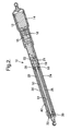
- hydraulic actuator 10 in accordance with an exemplary embodiment of the present invention is illustrated.
- hydraulic actuator 10 comprises an integrated, self contained, compact in-line hydraulic system.
- Hydraulic actuator 10 includes an electrical motor 12 disposed in a motor housing 14.
- the electric motor is coupled to a hydraulic pump 16 disposed in a pump housing 18, wherein the pump housing is secured to the motor housing.
- Many types of fluid pumps can be used in exemplary embodiments of the present invention. Some pumps include but are not limited to gear pumps, piston pumps, screw type pumps, or vane pumps, etc.
- Pump 16 is configured to provide fluid to a plurality of valve modules 20 and 22, which are disposed within an actuator housing or closed hydraulic cylinder 24.
- the fluid is a hydraulic fluid or any other suitable fluid having characteristics suitable for use in exemplary embodiments of the present invention.
- valve modules 20 and 22 are in fluid communication with the pump and chambers of the hydraulic actuator through optional transition plates 19 and 21.
- the transition plates will be used with an optional sensor system for determining the movement of the rod within the housing.
- the actuator may be configured to have a sensor that does not require a transition plate.
- actuator housing or closed hydraulic cylinder 24 Disposed within actuator housing or closed hydraulic cylinder 24 is an inner cylinder 25 defining a chamber for slidably receiving an output rod 26 that has a piston 28 at one end and an actuation end 29 at the other.
- the output rod is configured to move within a sealed opening 30 of an end cap 32 as piston 28 moves within a chamber 34 of cylinder 25.
- piston 28 is configured to provide a seal between chambers 42 and 44 via a seal ring 35 or a plurality of seal rings disposed about the periphery of the piston so that substantially no fluid from the first chamber may leak directly into the second chamber through the piston and vice versa as the piston moves within the chamber 34 of cylinder 25.
- the seal ring is a Teflon material disposed about the periphery of the piston.
- the seal ring comprises a copper material or copper alloy or equivalent thereof.
- an O-ring 37 may be used in conjunction with the seal ring wherein the O-ring is disposed between the seal ring and the piston by for example, the O-ring and the seal ring may be disposed in a groove 39 located on the surface of the piston.
- a stable device, guide device or wear ring or a plurality of wear rings 41 may be disposed about the piston and at either side of the seal ring to prevent rotation and twisting of the piston as the piston and rod move within the housing. This will prevent the piston from being angularly displaced, which may damage the housing and the seal about the rod.
- the guide device will ensure a more accurate sensing of the piston as it moves in the cylinder.
- cylinder 25 and accordingly chamber 34 is configured to be positioned within actuator housing 24 so that a compensator or compensation chamber or self-contained flexible volume compensator 36 is disposed between an exterior surface 38 of the cylinder 25 and an interior surface 40 of the actuator housing or closed hydraulic cylinder 24 thus providing a compensator 36 that surrounds or partially surrounds cylinder 25.
- the compensator provides a portion of the flow path between the first and second chambers thus additional flow conduits are not required.
- a first chamber 42 is disposed on one side of the piston and a second chamber 44 is positioned on the other side of the piston as the piston moves linearly within chamber 34.
- the volume or size of the first and second chambers will vary accordingly. This is due to the corresponding movement of piston 28 as rod 26 moves therein.
- the first chamber is in selective fluid communication with the compensation chamber and the second chamber via a valve system 46 disposed within the plurality of valve modules and the housings/cylinders.
- the valve system comprises a plurality of valves and flow channels.
- a first valve subassembly 45 will provide selective fluid communication between the self-contained flexible volume compensator 36, pump 14, and the first chamber 42 while a second valve subassembly 47 will provide selective fluid communication between the self-contained flexible volume compensator 36, pump 14 and the second chamber 44.
- first valve subassembly 45 comprises a counterbalance valve, a check valve and a pilot check valve some of which are configured to provide fluid flow in one direction only.
- second valve subassembly will also comprise a counterbalance valve, a check valve and a pilot check valve some of which are configured to provide fluid flow in one direction only. Again, other types of valve mechanisms may be employed.
- the motor is coupled to a control unit 48 wherein operational signals are provided to energize the motor that drives the pump to pump fluid to and from the first chamber, the second chamber and the self contained flexible volume compensator to manipulate the position of the output rod.
- the control unit or control module may be located within the actuator or remotely located as long as the operational signals to and from the control unit are capable of being received and transmitted.
- a sensor 50 is provided to provide signals indicative of the movement of the output rod to the control unit wherein the signals are used to energize or de-energize the motor corresponding to the position of the output rod.
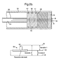
- the sensor is a transducer or variable resistor configured to track the movement or presence of the output rod and provide a signal indicative of the rod's position back to the control unit.
- sensor 50 is a potentiometer or variable resistor wherein a pot is used to as the primary choice of transducer for converting mechanical position of the rod and/or piston into an electrical signal that can be used by the controller. In accordance with an exemplary embodiment and as the rod and cylinder move the setting (and the resistance) of the pot is being changed.
- a pot generally has three wires R, W, B or terminals. Two are simply the connections to the ends of the resistive element. The remaining terminal connects to a moveable contact called the wiper 43.
- the wiper slides along the surface of the resistive element as the rod is moved and in an exemplary embodiment, the wiper is conductive and provides a conductive path between the resistive element and a wire. As the wiper is moved closer to one end of the resistive element, the resistance between the wiper terminal and that end terminal decreases thus, a signal (e.g., a voltage from a power source) indicative of the position of the rod is capable of being generated.
- the wiper is secured to the piston and as the same moves along the two other wires a signal indicative of the position of the rod is generated.
- the rod 26 is configured to have a hollow chamber 51 in which the transducer/sensor is positioned such that movement of the rod will be tracked by the sensor and a signal is outputted to the control unit wherein the signal is indicative of the movement of the rod.
- the piston is configured to have an opening 53, which allows the transducer to extend into the hollow chamber 51, the wires of the transducer to extend through opening 53 into the transition plate and ultimately to the control unit while the third or slider providing the electrical bridge is secured to the piston and/or interior of the rod and the position of the rod via the slider determines what percentage of an input voltage will be applied to the circuit of the sensor.
- opening 53 allows access to the hollow chamber 51 of the rod from chamber 44 it is understood that substantially no fluid passes directly from the first chamber to the second chamber through the rod and opening 53.
- sensing devices may be employed.
- one other non-limiting sensor is linear position sensor or linear variable differential transformer, or LVDT, wherein a series of inductors are positioned in a hollow cylindrical shaft and a solid cylindrical core is provided.
- LVDT linear variable differential transformer
- a LVDT will produce an electrical output proportional to the position of the core.
- two secondary coils are placed symmetrically on either side of a primary coil contained within the hollow cylindrical shaft.
- Movement of the magnetic core causes the mutual inductance of each secondary coil to vary relative to the primary, and thus the relative voltage induced from the primary coil to the secondary coil will vary as well.
- Non-limiting examples of such a sensor may be found at http://www.macrosensors.com .
- the core will be secured to the transition plate and the hollow shaft will vary the position of the coils with respect to the core.
- control unit will comprise a controller comprising a microcontroller, microprocessor, or other equivalent processing device capable of executing commands of computer readable data or program for executing a control algorithm.
- the controller may include, but not be limited to, a processor(s), computer(s), memory, storage, register(s), timing, interrupt(s), communication interfaces, and input/output signal interfaces, as well as combinations comprising at least one of the foregoing.
- the controller may include input signal filtering to enable accurate sampling and conversion or acquisitions of such signals from communications interfaces.
- exemplary embodiments of the present invention can be implemented through computer-implemented processes and apparatuses for practicing those processes.
- the sub-systems and components may be modulated and integrated as a single unit, which has a cylindrical housing of an extended linear configuration.
- the integration and assembly may vary based upon applications.
- the hydraulic cylinder may comprise the flexible compensator, the first and second chambers, the transition plates, the control module, which is secured to a pump module and a motor module.
- the elements are all designed and arranged in-line with the hydraulic cylinder so that a compact package, particularly compact in diameter, can be achieved.
- the compact in-line hydraulic system with optional modules may be assembled together within a tube-like housing.
- Valve system 46 includes a plurality of fluid flow channels and ports among the pump, control units, and the flexible volume device.
- the valve system is designed so that channels and ports may be connected through the parallel surfaces.
- the selection of integrated-modulated hydraulic units may be optional and exchangeable based upon the application requirements.
- control modules or valve modules comprise various hydraulic valve(s), which may be designed and integrated into the control modules.
- the functions of the control valves and/or module(s) may include, but not limited to, a counterbalance module, a cross over relief module, and a pilot check module, etc.
- a counterbalance module a counterbalance module
- a cross over relief module a cross over relief module
- a pilot check module a pilot check module
- the self contained flexible volume device is pre-loaded or pre-pressurized to a predetermined pressure.
- the means to pre-load, or pre-pressure the flexible volume device include, but are not limited to, spring loading the compensator, an accumulator with compressed air, or a pressurized bladder made from rubber-like materials.
- the bladder is a flexible rubber like material 55 ( Figure 4) and the bladder is inserted between the inner cylinder and the outer housing and a spring 57 is positioned to maintain a pre-determined amount of pressure upon the bladder. In this embodiment no gas or air is found in the self contained flexible volume device.
- the hydraulic actuator is sealed and self contained so that no air or gas is found in the first chamber, the second chamber, the pump and the valve system or systems interconnecting each of the components thus in accordance with exemplary embodiments of the present invention only the self contained flexible volume device may have compressed air therein, which is provided only to maintain the fluid in the self contained flexible volume device at a predetermined positive pressure and this air does not escape into other portions of the actuator.
- other embodiments contemplate pressurizing the self contained flexible volume device wherein no gas or air is in the system at all other than perhaps an external pressure to a flexible compensator.
- the hydraulic actuator has a self-contained flexible volume compensator.
- the self-contained flexible volume compensator balances the volume between the first chamber and the second chamber.
- the volume compensator is pre-loaded, or pre-pressurized by means of spring load, compressed air, which may be external or internal to the self-contained flexible volume compensator wherein a low positive pressure (e.g., approximately 100 psi) in the self-contained flexible volume compensator is provided to have selective fluid communication with at least one chamber being at a high pressure in order to facilitate movement of the piston and rod.
- the self-contained flexible volume compensator is a flexible bladder made from rubber-like materials, etc.
- the pressurized volume compensator is self-contained and not open to the atmosphere.
- the self-contained flexible volume compensator is pre-pressurized to a low pressure, which in one exemplary embodiment is less than 100 psi but greater that 1 atmosphere, although pressures greater or less than 100 psi are also contemplated and the active chamber or chamber (e.g., first chamber 42 or second chamber 44) forcing the movement of the piston is pressurized to a high pressure e.g., 300-3000 psi in order to facilitate the movement of the piston and rod within the chamber.
- first and second chambers are and associated valves are configured for high pressures to facilitate movement while the self-contained flexible volume compensator is pre-pressurized to at least a low pressure respective to the high pressure chamber, which allows transfer of fluid into the self-contained flexible volume compensator as well as transfer of fluid out of the self-contained flexible volume compensator.
- the pressurized volume compensator will push fluid out of the volume compensator into the pump when the cylinder and rod is extending and the fluid will be pumped back into the volume compensator when the cylinder and rod is retracted regardless of the location and/or orientation of the volume compensator since it is pre-pressurized and self-sealed.
- the self-contained flexible volume compensator may be located anywhere between modules, such as between the cylinder and valves, or between the valves and pump module. It can also be located between an inner housing defining the first chamber and the second chamber and the outer housing the inner housing is located in.
- volume compensator can also function as an accumulator with ability to provide an output as self-assistance to the actuation of the device.
- self-contained flexible volume compensator can be installed and operated in any orientation.
- the valve system has a plurality of valves for providing selective fluid communication among the chambers, the pump, and the self-contained flexible volume compensator.
- the valve system and the hydraulic actuator will operate in numerous modes, manual extraction, manual retraction, powered extraction, powered retraction and lock out.
- the closed hydraulic cylinder comprises a piston, a plurality of flow channels, an outer tube or housing, a movable inner tube as an output rod, an optional position or pressure sensor system positioned within the output rod, a pair of end caps (e.g., a top cap, a base cap, and seals).
- a flow channel may be located between the inner and outer tubes positioned between the top and base caps the flow channel will connect the upper chamber and an inlet channel.
- the movable tube may also be an optional inner flow channel, or as a housing for the optional position sensor system.
- stable device or wear ring between the piston and the inner wall provides piston with smooth movement and prevents inaccuracies in the optional sensor system.
- the top cap will have an opening for the output rod.
- the base cap will have ports which connect with additional modulated hydraulic units.
- the modulated hydraulic units comprising the pump and motor modules may be attached to the base cap in sequence.
- the self-contained flexible volume device may be located anywhere between modules, such as between the cylinder and valves, or between the valves and pump module.
- the pump is pressurizing the right side or the second chamber 44 of the cylinder.
- the bidirectional pump 14 causes the pressurized fluid to flow through a top check valve 54 at the right of Figure 4 allowing fluid to enter the right side chamber.
- This fluid pressure also opens a bottom pilot check valve 56, which allows extra fluid flow out of the volume compensator 36 into the pump.
- Figure 4 shows the self contained flexible volume compensator as being pre-pressurized by for example a spring biasing means 57 thus, no air is in the compensator or system.
- the self contained flexible volume compensator may be located anywhere with the hydraulic actuator.
- the moving piston in the direction of arrow 52 increases the fluid pressure within the left side chamber until it reaches the setting point of a counterbalance valve 58.
- Counterbalance valve 58 then opens and the fluid flows out of the left side chamber or the first chamber through counterbalance valve 58 and into the pump.
- the pump is pressurizing the left side or the first chamber of the cylinder.
- the pressurized fluid flows through a check valve 60 and enters the left side or the first chamber.
- the moving piston increases the fluid pressure within the right side chamber or the second chamber until it reaches the setting point of a counterbalance valve 62.
- the counterbalance valve 62 then opens and the fluid flows out of the right side chamber through it and into the pump.
- the pumping fluid pressure at the left side also opens a bottom pilot check valve 64, which allows the extra fluid out of the right side chamber or second chamber 44 to flow into the volume compensator as well as it is not necessary for movement of the rod and piston in the direction of arrow 59.
- the pilot check valve 64 opens and the excessive fluid will flow back into the compensator as the extra fluid from the second chamber is not necessary due to the reduced volume caused by the presence of the rod in chamber 42.
- moving the piston all the way to end plate 32 will create a greater volume in chamber 44 than a volume created in chamber 42 when the piston is moved all the way to the opposite plate again due to the presence of the rod in the chamber thus, the self-contained flexible volume device or compensator 36 compensates for the need of extra fluid in one operation and lack thereof in another operation.
- pilot check valve 56 may be replaced with a one way check valve as long as the sucking pressure of the pump will open the valve since only flow out of the compensator for actuating the rod in the direction of arrow 52 may be required while two way flow is required from valve 64 as the rod moves in the directions of arrows 52 and 59.
- the moving piston increases the fluid pressure within the left side chamber or the first chamber until it reaches the setting point of the counterbalance valve 58. Then the counterbalance valve 58 opens and the fluid flows out of the left side chamber through the counterbalance valve 58 and then the pressure also opens a middle crossover check valve 68 comprising a portion of a cross over relief module 49, which in accordance with an exemplary embodiment of the present invention provides at least two functions 1) a bypass relief when the piston has completely traveled to one side of the chamber and the pump is still pressurizing the active chamber and 2) a manual bypass or override when the rod is being manipulated manually and the pump is not activated.
- the fluid then flows through the middle crossover check valve 68 and the check valve 54 into the right side chamber.
- the pressure also opens the pilot check valve 56, which allows the extra fluid flows out of the volume compensator into the right side chamber.
- the pressurized fluid of the self contained flexible volume compensator will assist in the extraction.
- the moving piston increases the fluid pressure within the right side chamber or second chamber until it reaches the setting point of the counterbalance valve 62.
- the counterbalance valve 62 then opens and the fluid flows out of the right side chamber through it and then the pressure also opens a middle crossover check valve 70 to open.
- the fluid then flows through the middle crossover check valve 70 and the valve 60 into the left side chamber.
- the pressure also opens the pilot check valve 64, which allows the extra fluid flows into the volume compensator from the right side chamber or second chamber.
- the system has an optional position sensor, which can be located at the side of the cylinder, middle of the cylinder, side or center of the rod.
- the system may be programmable to stop and start at any position within the operation range if required and based upon the sensor output.
- the system may be programmable to a desirable speed profile within the operation range if required.
- the system may be programmable for a manual-to-power-start feature within the operation range if required. In other words when the actuator is manipulated manually and the sensor detects movement a signal is sent to the controller to activate the motor and provide powered retraction and/or extraction of the rod.
- FIG. 5 another control scheme of an exemplary embodiment of the present invention is illustrated.
- the self-contained flexible volume compensator is shown disposed around the housing defining the first and second chambers.
- a bypass valve 80 as an override (bypass) feature for emergency operation when power fails, or service operation as required.
- the bypass valve can be opened, manually or by system setting and the chambers within the cylinder and the self-contained volume compensator are connected and fluid can flow through valves when driven manually.
- the system thus, can be driven manually.
- the valve system also comprises a plurality of counterbalance valves 82, check valves 84 and pilot check valves 86.
- Figures 6-8 illustrate alternative configurations wherein the self-contained flexible volume compensator is located in various positions within the housing.
- Figure 9 illustrates a vehicle lift gate being operated by a hydraulic actuator in accordance with an exemplary embodiment of the present invention.
- the hydraulic actuator may be secured between a door and body of a vehicle in two ways, either the rod is secured to the door and the motor housing end is secured to the body of the vehicle, or the rod is secured to the body and the motor housing end is secured to the door of the vehicle.
Landscapes
- Engineering & Computer Science (AREA)
- Physics & Mathematics (AREA)
- Fluid Mechanics (AREA)
- Mechanical Engineering (AREA)
- General Engineering & Computer Science (AREA)
- Fluid-Pressure Circuits (AREA)
Applications Claiming Priority (1)
| Application Number | Priority Date | Filing Date | Title |
|---|---|---|---|
| US75766306P | 2006-01-10 | 2006-01-10 |
Publications (2)
| Publication Number | Publication Date |
|---|---|
| EP1806506A2 true EP1806506A2 (de) | 2007-07-11 |
| EP1806506A3 EP1806506A3 (de) | 2009-04-22 |
Family
ID=37908119
Family Applications (1)
| Application Number | Title | Priority Date | Filing Date |
|---|---|---|---|
| EP07075005A Withdrawn EP1806506A3 (de) | 2006-01-10 | 2007-01-04 | Kompaktes hydraulisches Betätigungssystem |
Country Status (2)
| Country | Link |
|---|---|
| US (1) | US20070157612A1 (de) |
| EP (1) | EP1806506A3 (de) |
Cited By (6)
| Publication number | Priority date | Publication date | Assignee | Title |
|---|---|---|---|---|
| DE102007023414A1 (de) * | 2007-05-18 | 2008-11-20 | Rehau Ag + Co. | Hydraulik-Antriebseinheit |
| EP2811162A4 (de) * | 2012-01-30 | 2015-11-25 | Jong Hee Lee | Intelligentes hybrid-stellglied |
| EP3112698A1 (de) * | 2015-06-30 | 2017-01-04 | Goodrich Actuation Systems SAS | Elektrische hydrostatische aktuatoren |
| CN109797697A (zh) * | 2017-12-31 | 2019-05-24 | 金砚权 | 双端伸出装置 |
| EP3730806A1 (de) * | 2019-04-24 | 2020-10-28 | Piston Power s.r.o. | Hydraulische aktuatoranordnung |
| EP3669086A4 (de) * | 2017-08-16 | 2021-05-12 | Kyntronics, Inc. | Elektrohydraulisches stellglied |
Families Citing this family (27)
| Publication number | Priority date | Publication date | Assignee | Title |
|---|---|---|---|---|
| US8161742B2 (en) * | 2007-08-07 | 2012-04-24 | Parker-Hannifin Corporation | Electro-hydraulic actuator mounting |
| US20090139141A1 (en) * | 2007-11-30 | 2009-06-04 | Macleod Michael Fergus | Automatic door opener |
| MX2011007715A (es) * | 2009-01-22 | 2011-09-28 | Inspired Surgical Technologies Inc | Sistema de rastreo solar controlado, accionado por prealimentacion. |
| WO2010141605A1 (en) * | 2009-06-03 | 2010-12-09 | Control Products Inc. | Hydraulic accumulator with position sensor |
| WO2011159874A2 (en) * | 2010-06-16 | 2011-12-22 | Levant Power Corporation | Integrated energy generating damper |
| US8978766B2 (en) * | 2011-09-13 | 2015-03-17 | Schlumberger Technology Corporation | Temperature compensated accumulator |
| US9677573B2 (en) * | 2014-02-14 | 2017-06-13 | Cameron International Corporation | Measurement system |
| CA2940679C (en) | 2014-02-28 | 2022-07-19 | Project Phoenix, LLC | Pump integrated with two independently driven prime movers |
| WO2015148662A1 (en) | 2014-03-25 | 2015-10-01 | Afshari Thomas | System to pump fluid and control thereof |
| EP3134648B1 (de) | 2014-04-22 | 2023-06-14 | Project Phoenix, LLC | Flüssigkeitsabgabesystem mit einer welle mit durchgang |
| EP3149362B1 (de) | 2014-06-02 | 2019-04-10 | Project Phoenix LLC | Hydrostatische getriebeanordnung und system |
| EP3730793B1 (de) * | 2014-06-02 | 2022-04-27 | Project Phoenix LLC | Linearaktuatoranordnung und -system |
| CA2955017C (en) | 2014-07-22 | 2023-05-09 | Project Phoenix, LLC | External gear pump integrated with two independently driven prime movers |
| US10072676B2 (en) | 2014-09-23 | 2018-09-11 | Project Phoenix, LLC | System to pump fluid and control thereof |
| WO2016057321A1 (en) | 2014-10-06 | 2016-04-14 | Afshari Thomas | Linear actuator assembly and system |
| WO2016064569A1 (en) | 2014-10-20 | 2016-04-28 | Afshari Thomas | Hydrostatic transmission assembly and system |
| DE202014105923U1 (de) * | 2014-12-08 | 2016-03-09 | Woco Industrietechnik Gmbh | Hydraulischer Motorraumaktuator mit Hydromotorantrieb |
| EP3828416A1 (de) | 2015-09-02 | 2021-06-02 | Project Phoenix LLC | System zum pumpen einer flüssigkeit und steuerung dafür |
| WO2017040792A1 (en) | 2015-09-02 | 2017-03-09 | Project Phoenix, LLC | System to pump fluid and control thereof |
| WO2018217720A1 (en) * | 2017-05-23 | 2018-11-29 | Borgwarner Inc. | Pressure centering selectable one way clutch actuator |
| US11118610B2 (en) * | 2017-08-29 | 2021-09-14 | The Boeing Company | Low profile electro-hydrostatic actuator |
| CN108468673A (zh) * | 2018-05-21 | 2018-08-31 | 北京科技大学 | 一种适用于深海工作环境的液压油缸 |
| CN109356906B (zh) * | 2018-12-04 | 2024-02-06 | 北京科技大学 | 一种可用于水下作业的集成式电液执行器 |
| DE102019202683A1 (de) * | 2019-02-28 | 2020-09-03 | Robert Bosch Gmbh | Nachfülleinheit zum Nachfüllen von Hydrauliköl in ein mit einem Niederdruckspeicher druckvorgespanntes hydraulisches System und druckvorgespanntes hydraulisches System mit einer solchen Nachfülleinheit |
| US20230392616A1 (en) * | 2020-11-06 | 2023-12-07 | G.W. Lisk Company, Inc. | Electro-hydrostatic actuator |
| CN113931903B (zh) * | 2021-10-13 | 2024-03-08 | 宁波友联智能科技有限公司 | 一种智能电液执行器 |
| EP4279749A1 (de) * | 2022-05-20 | 2023-11-22 | Power Hydraulik S.r.l. | Hydraulische verriegelungsvorrichtung |
Citations (5)
| Publication number | Priority date | Publication date | Assignee | Title |
|---|---|---|---|---|
| US2640323A (en) * | 1950-12-15 | 1953-06-02 | Detroit Harvester Co | Power unit of the fluid pressure type |
| US5181380A (en) * | 1990-09-19 | 1993-01-26 | Aerospatial Societe Nationale Industrielle | Hydrostatic operating mode hydraulic actuator preferably for backup operation, and flight control system comprising it |
| US20010022083A1 (en) * | 2000-03-17 | 2001-09-20 | Festo Ag & Co. | Drive device |
| FR2823803A1 (fr) * | 2001-04-23 | 2002-10-25 | Valeo | Actionneur electro-hydraulique, notamment pour la commande d'un embrayage de vehicule automobile |
| US6519939B1 (en) * | 1999-07-30 | 2003-02-18 | M-Mac Actuators, Inc. | Hydraulic system, manifold and volumetric compensator |
Family Cites Families (7)
| Publication number | Priority date | Publication date | Assignee | Title |
|---|---|---|---|---|
| US2457467A (en) * | 1945-03-08 | 1948-12-28 | Cons Vultee Aircraft Corp | Electrically and hydraulically operated extensible strut |
| US2927429A (en) * | 1958-05-01 | 1960-03-08 | Carlson Martin | Reversible hydraulic door operator system |
| US5444979A (en) * | 1992-04-30 | 1995-08-29 | Showa Corporation | Fluid passage control device for fluid pressure actuator |
| US6282893B1 (en) * | 1999-08-19 | 2001-09-04 | Delaware Capital Formation, Inc. | Self-contained actuator |
| US6979185B2 (en) * | 2000-08-01 | 2005-12-27 | Kaempe Staffan I | Bi-rotational pump/hydraulic actuator |
| FR2831226B1 (fr) * | 2001-10-24 | 2005-09-23 | Snecma Moteurs | Actionneur electrohydraulique autonome |
| DE10234355A1 (de) * | 2002-07-27 | 2004-02-05 | Stabilus Gmbh | Kolben-Zylinder-Einheit |
-
2007
- 2007-01-01 US US11/618,924 patent/US20070157612A1/en not_active Abandoned
- 2007-01-04 EP EP07075005A patent/EP1806506A3/de not_active Withdrawn
Patent Citations (5)
| Publication number | Priority date | Publication date | Assignee | Title |
|---|---|---|---|---|
| US2640323A (en) * | 1950-12-15 | 1953-06-02 | Detroit Harvester Co | Power unit of the fluid pressure type |
| US5181380A (en) * | 1990-09-19 | 1993-01-26 | Aerospatial Societe Nationale Industrielle | Hydrostatic operating mode hydraulic actuator preferably for backup operation, and flight control system comprising it |
| US6519939B1 (en) * | 1999-07-30 | 2003-02-18 | M-Mac Actuators, Inc. | Hydraulic system, manifold and volumetric compensator |
| US20010022083A1 (en) * | 2000-03-17 | 2001-09-20 | Festo Ag & Co. | Drive device |
| FR2823803A1 (fr) * | 2001-04-23 | 2002-10-25 | Valeo | Actionneur electro-hydraulique, notamment pour la commande d'un embrayage de vehicule automobile |
Cited By (11)
| Publication number | Priority date | Publication date | Assignee | Title |
|---|---|---|---|---|
| DE102007023414A1 (de) * | 2007-05-18 | 2008-11-20 | Rehau Ag + Co. | Hydraulik-Antriebseinheit |
| DE102007023414B4 (de) * | 2007-05-18 | 2010-11-11 | Rehau Ag + Co. | Hydraulik-Antriebseinheit |
| EP2811162A4 (de) * | 2012-01-30 | 2015-11-25 | Jong Hee Lee | Intelligentes hybrid-stellglied |
| EP3112698A1 (de) * | 2015-06-30 | 2017-01-04 | Goodrich Actuation Systems SAS | Elektrische hydrostatische aktuatoren |
| US10087962B2 (en) | 2015-06-30 | 2018-10-02 | Goodrich Actuation Systems Sas | Electro hydrostatic actuators |
| US10611464B2 (en) | 2015-06-30 | 2020-04-07 | Goodrich Actuation Systems Sas | Electro hydrostatic actuators |
| EP3669086A4 (de) * | 2017-08-16 | 2021-05-12 | Kyntronics, Inc. | Elektrohydraulisches stellglied |
| CN109797697A (zh) * | 2017-12-31 | 2019-05-24 | 金砚权 | 双端伸出装置 |
| EP3730806A1 (de) * | 2019-04-24 | 2020-10-28 | Piston Power s.r.o. | Hydraulische aktuatoranordnung |
| CN111852964A (zh) * | 2019-04-24 | 2020-10-30 | 活塞动力有限责任公司 | 液压致动器布置 |
| US11454260B2 (en) | 2019-04-24 | 2022-09-27 | Pistonpower Aps | Hydraulic actuator arrangement |
Also Published As
| Publication number | Publication date |
|---|---|
| US20070157612A1 (en) | 2007-07-12 |
| EP1806506A3 (de) | 2009-04-22 |
Similar Documents
| Publication | Publication Date | Title |
|---|---|---|
| EP1806506A2 (de) | Kompaktes hydraulisches Betätigungssystem | |
| US7434395B2 (en) | Apparatus and method for dual mode compact hydraulic system | |
| US6711984B2 (en) | Bi-fluid actuator | |
| RU2124666C1 (ru) | Предварительно управляемый сервоклапан | |
| EP0763174B1 (de) | Ventilstellglied | |
| CA2711398C (en) | Solenoid valve assembly | |
| US20090165457A1 (en) | Double redundancy electro hydrostatic actuator system | |
| US20200300275A1 (en) | Valve device | |
| US9958085B2 (en) | Flow control valve having a motion conversion device | |
| EP1498614A3 (de) | Elektro-hydrostatisches Stellglied mit einem pannensicheren System | |
| JPH076531B2 (ja) | 油圧制御装置 | |
| EP2868932B1 (de) | Vollintegrierter elektrohydraulischer Linearaktuator | |
| KR102207185B1 (ko) | 유량 제어 밸브 장치 | |
| EP0164347B1 (de) | Flüssigkeitsbetätigter stellantrieb für die stufenweise regelung von ventilen | |
| US8973890B2 (en) | Fluid-operated actuating drive on a valve | |
| US8210206B2 (en) | Dual redundant servovalve | |
| WO2018192747A1 (de) | Elektrohydraulisches system für den einsatz unter wasser mit einem elektrohydraulischen stellantrieb | |
| WO2021079288A4 (en) | Shock absorber assembly with adjustable height | |
| WO2013177437A1 (en) | Electro-hydraulic valve positioner | |
| US3360930A (en) | Electro-hydraulic valve operator | |
| US3114296A (en) | Linear actuator | |
| US20240060515A1 (en) | Fluid pressure driving device | |
| JPS63115905A (ja) | 事前制御装置 | |
| WO2014066627A1 (en) | Hydraulic high pressure valve controller using the in-situ pressure difference | |
| DE10116995A1 (de) | Hydraulikeinrichtung und Anordnung von Hydraulikeinrichtung und Steuergerät |
Legal Events
| Date | Code | Title | Description |
|---|---|---|---|
| PUAI | Public reference made under article 153(3) epc to a published international application that has entered the european phase |
Free format text: ORIGINAL CODE: 0009012 |
|
| AK | Designated contracting states |
Kind code of ref document: A2 Designated state(s): AT BE BG CH CY CZ DE DK EE ES FI FR GB GR HU IE IS IT LI LT LU LV MC NL PL PT RO SE SI SK TR |
|
| AX | Request for extension of the european patent |
Extension state: AL BA HR MK YU |
|
| PUAL | Search report despatched |
Free format text: ORIGINAL CODE: 0009013 |
|
| AK | Designated contracting states |
Kind code of ref document: A3 Designated state(s): AT BE BG CH CY CZ DE DK EE ES FI FR GB GR HU IE IS IT LI LT LU LV MC NL PL PT RO SE SI SK TR |
|
| AX | Request for extension of the european patent |
Extension state: AL BA HR MK RS |
|
| AKX | Designation fees paid | ||
| STAA | Information on the status of an ep patent application or granted ep patent |
Free format text: STATUS: THE APPLICATION IS DEEMED TO BE WITHDRAWN |
|
| 18D | Application deemed to be withdrawn |
Effective date: 20091023 |
|
| REG | Reference to a national code |
Ref country code: DE Ref legal event code: 8566 |