EP1806002B1 - Verfahren zur verwaltung von betriebsmitteln in einer plattform für telekommunikationsdienst und/oder netzverwaltung, entsprechende plattform und computerprogrammprodukt dafür - Google Patents
Verfahren zur verwaltung von betriebsmitteln in einer plattform für telekommunikationsdienst und/oder netzverwaltung, entsprechende plattform und computerprogrammprodukt dafür Download PDFInfo
- Publication number
- EP1806002B1 EP1806002B1 EP04822335A EP04822335A EP1806002B1 EP 1806002 B1 EP1806002 B1 EP 1806002B1 EP 04822335 A EP04822335 A EP 04822335A EP 04822335 A EP04822335 A EP 04822335A EP 1806002 B1 EP1806002 B1 EP 1806002B1
- Authority
- EP
- European Patent Office
- Prior art keywords
- agents
- platform
- resources
- executions
- agent
- Prior art date
- Legal status (The legal status is an assumption and is not a legal conclusion. Google has not performed a legal analysis and makes no representation as to the accuracy of the status listed.)
- Active
Links
- 238000000034 method Methods 0.000 title claims abstract description 181
- 238000004590 computer program Methods 0.000 title claims description 6
- 230000008569 process Effects 0.000 claims abstract description 141
- 238000012544 monitoring process Methods 0.000 claims abstract description 27
- 238000012545 processing Methods 0.000 claims abstract description 10
- 238000007726 management method Methods 0.000 claims description 30
- 238000013439 planning Methods 0.000 claims description 8
- 238000011156 evaluation Methods 0.000 claims description 7
- 238000012986 modification Methods 0.000 claims description 4
- 230000004048 modification Effects 0.000 claims description 4
- 230000008859 change Effects 0.000 claims description 3
- 230000003542 behavioural effect Effects 0.000 claims description 2
- 230000006978 adaptation Effects 0.000 description 14
- 230000009471 action Effects 0.000 description 12
- 230000006870 function Effects 0.000 description 8
- 230000003993 interaction Effects 0.000 description 7
- 101150012579 ADSL gene Proteins 0.000 description 6
- 102100020775 Adenylosuccinate lyase Human genes 0.000 description 6
- 108700040193 Adenylosuccinate lyases Proteins 0.000 description 6
- 238000004891 communication Methods 0.000 description 6
- 238000010586 diagram Methods 0.000 description 6
- 230000003044 adaptive effect Effects 0.000 description 5
- 238000004458 analytical method Methods 0.000 description 5
- 230000000875 corresponding effect Effects 0.000 description 5
- 230000006399 behavior Effects 0.000 description 4
- 230000007423 decrease Effects 0.000 description 3
- 238000009826 distribution Methods 0.000 description 3
- 235000003642 hunger Nutrition 0.000 description 3
- 230000007246 mechanism Effects 0.000 description 3
- 238000005457 optimization Methods 0.000 description 3
- 230000037351 starvation Effects 0.000 description 3
- 238000013459 approach Methods 0.000 description 2
- 230000001276 controlling effect Effects 0.000 description 2
- 238000012937 correction Methods 0.000 description 2
- 238000013499 data model Methods 0.000 description 2
- 230000000694 effects Effects 0.000 description 2
- 238000012417 linear regression Methods 0.000 description 2
- 230000004044 response Effects 0.000 description 2
- 230000011218 segmentation Effects 0.000 description 2
- 238000012360 testing method Methods 0.000 description 2
- 241000251730 Chondrichthyes Species 0.000 description 1
- 230000002776 aggregation Effects 0.000 description 1
- 238000004220 aggregation Methods 0.000 description 1
- 230000008901 benefit Effects 0.000 description 1
- 230000015556 catabolic process Effects 0.000 description 1
- 230000002596 correlated effect Effects 0.000 description 1
- 238000006731 degradation reaction Methods 0.000 description 1
- 230000000593 degrading effect Effects 0.000 description 1
- 230000001419 dependent effect Effects 0.000 description 1
- 238000011161 development Methods 0.000 description 1
- 230000018109 developmental process Effects 0.000 description 1
- 238000005516 engineering process Methods 0.000 description 1
- 230000014509 gene expression Effects 0.000 description 1
- 238000003780 insertion Methods 0.000 description 1
- 230000037431 insertion Effects 0.000 description 1
- 230000007774 longterm Effects 0.000 description 1
- 230000008520 organization Effects 0.000 description 1
- 238000011002 quantification Methods 0.000 description 1
- 230000001373 regressive effect Effects 0.000 description 1
- 238000005070 sampling Methods 0.000 description 1
- 238000000638 solvent extraction Methods 0.000 description 1
- 230000002269 spontaneous effect Effects 0.000 description 1
- 238000003860 storage Methods 0.000 description 1
- 230000036962 time dependent Effects 0.000 description 1
- 238000012384 transportation and delivery Methods 0.000 description 1
- 230000001960 triggered effect Effects 0.000 description 1
Images


Classifications
-
- H—ELECTRICITY
- H04—ELECTRIC COMMUNICATION TECHNIQUE
- H04Q—SELECTING
- H04Q3/00—Selecting arrangements
- H04Q3/0016—Arrangements providing connection between exchanges
- H04Q3/0062—Provisions for network management
- H04Q3/0087—Network testing or monitoring arrangements
-
- G—PHYSICS
- G06—COMPUTING; CALCULATING OR COUNTING
- G06F—ELECTRIC DIGITAL DATA PROCESSING
- G06F15/00—Digital computers in general; Data processing equipment in general
- G06F15/16—Combinations of two or more digital computers each having at least an arithmetic unit, a program unit and a register, e.g. for a simultaneous processing of several programs
-
- H—ELECTRICITY
- H04—ELECTRIC COMMUNICATION TECHNIQUE
- H04L—TRANSMISSION OF DIGITAL INFORMATION, e.g. TELEGRAPHIC COMMUNICATION
- H04L41/00—Arrangements for maintenance, administration or management of data switching networks, e.g. of packet switching networks
- H04L41/50—Network service management, e.g. ensuring proper service fulfilment according to agreements
- H04L41/5003—Managing SLA; Interaction between SLA and QoS
- H04L41/5009—Determining service level performance parameters or violations of service level contracts, e.g. violations of agreed response time or mean time between failures [MTBF]
-
- H—ELECTRICITY
- H04—ELECTRIC COMMUNICATION TECHNIQUE
- H04L—TRANSMISSION OF DIGITAL INFORMATION, e.g. TELEGRAPHIC COMMUNICATION
- H04L41/00—Arrangements for maintenance, administration or management of data switching networks, e.g. of packet switching networks
- H04L41/04—Network management architectures or arrangements
- H04L41/046—Network management architectures or arrangements comprising network management agents or mobile agents therefor
Definitions
- the present invention relates to a method for managing resources in a platform directed to manage telecommunication networks and/or services.
- the invention concerns a method for allocating resources in platforms for management of telecommunications networks and/or services and a corresponding management platform.
- management platforms which include a plurality of components such as Operations Support Systems (OSS) organized on hierarchical architectures, sometimes based on agents.
- OSS Operations Support Systems
- US 6 243 396 discloses, for example, a communication network management system or platform having a multi-layer hierarchical architecture of interconnected management authorities controlling telecommunication network resources.
- Each authority has a number of agents responsible for the execution of processes, which may be intelligent or simply reactive agents.
- the reactive agents are located within a platform part of the authority and the intelligent agents are located within a controlling part of the authority.
- the intelligent and reactive agents are grouped into functional components to provide FCAPS (Fault, Configuration, Accounting, Performance, Security) functionalities to the platform.
- FCAPS ault, Configuration, Accounting, Performance, Security
- WO 01/02973 teaches use a platform comprising a centralised process coordinator for coordination of distributed agents, typically realized with a workflow engine running workflow descriptions (similar to flowcharts) which comprise delegation of jobs to components (the agents), collection of responses from agents, and so on.
- a task can be the completion of a determined process in an average time shorter than a predefined time duration, or the completion of a determined number of processes within a fixed deadline.
- Huge workload on an agent may prevent the agent from completing the task in a predefined average time or within the fixed deadline therefore causing the business goal not to be reached.
- US 2003/0036886 discloses a monitoring and control engine for multi-tiered service-level-management of distributed web-application servers.
- Web site provides services to users over the Internet.
- End-user service-level objectives (SLOs) such as availability and performance are measured and reported to a SLO agent.
- SLOs service-level objectives
- User requests pass through several tiers at the web site, such as a firewall tier, a web-server tier, an application-server tier, and a database-server tier. Each tier has several redundant service components that can process requests for that tier.
- Local agents operating with any local resource managers, monitor running service components and report to a service agent. Node monitors also monitor network-node status and report to the service agent.
- the service agent When a node or service component fails, the service agent attempts to restart it using the local agent, or replicates the service component to other nodes.
- the SLO agent determines that a SLO is not being met, it instructs the service agent to replicate more of the constraining service components or increase resources.
- US2003/0233391 discloses a method and system for allocating computer resources.
- the method may be implemented in software instructions in a resource allocator that allocates resources among workloads operating on the system.
- Parameters defining service level objectives for the execution of workloads are received from a user input device.
- At least one of the service level objectives is a utilization cap that limits the overall allocation of system resources among the workloads.
- the parameters include priorities for the service level objectives, including the utilization cap.
- utilization data is received indicating usage of system resources. Resources are allocated to the workloads according to the priorities of the service level objectives and based on the utilization data.
- Object of the present invention is therefore to provide a method for managing resources of an agent-based platform for managing telecommunications services and/or networks, which improves the efficiency of the platform by achieving the optimal performance in resource utilization in order to fulfil predetermined business goals.
- Another object of the invention is a management platform having a decentralized process logic in order to achieve better performances of the platform while improving its flexibility.
- the invention discloses a method and a corresponding platform based on a predictive and adaptive mechanism driven by predetermined indicators (e.g. business key indicators) and goals, which provides for the measuring and automatic control of IT resources utilization in a management platform.
- predetermined indicators e.g. business key indicators
- the architectural features of the platform according to the invention are:
- a Re-allocator Console is provided as a Graphical User Interface to define resource reallocation rules, and a Monitoring Console is provided, which allows to control SLA fulfilment trends and corresponding IT resources utilization and related costs.
- Process engines inside agents proves to be an advantageous feature for dynamic allocation of IT resources between agents, improving flexibility without introducing bottlenecks, which is the case when all engines are placed in a centralized process coordinator.
- Process engines inside agents allow to measure resource utilization in the agents analytically (for example CPU time or RAM used) for each functionality execution (i.e. process execution).
- Process descriptions in the centralized database are distributed across the platform to each agent for use within their process engines, achieving automatic synchronization with all operating functionalities of the platform, so that it is possible to tune the resource management procedures working with the semantic of the jobs.
- an administrator of the platform for managing telecommunications services and networks can build any FCAPS (Fault, Configuration, Accounting, Performance, Security) functionality defining in the process database one or more workflows and/or rules or combining existing ones; then automatically the agents acquire the new process (workflow and rules) definitions and run them when needed.
- FCAPS fault, Configuration, Accounting, Performance, Security
- the Goal Console permits to define SLA and priority on new processes.
- the Control Agents allow to control SLA trends and corresponding IT resources utilization for the new processes so that the Re-allocator module may optimize the overall configuration, i.e. change workflows priorities at an agent or supply it with more computational resources (CPU, memory, etc).
- Resource management is preferably implemented in the platform by a centralized module (a Manager Module) together with distributed modules (Control Agents).
- a Manager Module a centralized module
- Control Agents distributed modules
- the combination of centralized and distributed functionalities is the basis of the adaptive mechanism of the solution.
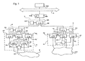
- Figure 1 depicts an exemplary architecture of a system for managing telecommunications services and networks according to the invention.
- the system is preferably implemented on a distributed processing architecture comprising a plurality of processing host machines H, each of which may include one or more software agents (A1, A2, A3).
- the system (or platform) comprises a centralized control module or Manager Module MM including a program or set of programs running on a host machine and interacting with distributed agents for various coordination actions, like distribution of process descriptions, invocation of operations, administrative controls, etc.
- the Manager module MM may also preferably include a graphical user interface for interaction with a user such as a system administrator.
- the term process is used for representing one or more workflows, one or more rules or, preferably, a combination of one or more workflows and one or more rules.
- the workflow can be defined as the automation of a business procedure during which information or tasks are passed from one agent to another for action, according to a set of procedural rules.
- the workflow can be represented through a flowchart with a sequence of tasks as well as time and logical dependencies between tasks including alternative or parallel branches.
- the rules are declarations of which actions have to be executed when a specific set of conditions/events occurs.
- the manager module MM comprises a process description database PDB, which is arranged to store all the processes, i.e. workflows and rules, representing the behavioural and functional aspects of the platform.
- the database PDB further comprises, for example, data models handled by workflows and rules.
- the process description database PDB can be associated with, for example, the catalogue part of any conventional Network Inventory system as known to a man skilled in the art.
- the architecture of figure 1 includes a plurality of multi-layered Agent Modules, three layers having been shown as a way of example including some agents A1, A2, A3 respectively. Agents belonging to the same level may be connected to each other or may be independent from each other. They are coupled to an agent of higher level, if any. At the lower level an agent is coupled to a network element under control (generally shown as the communication network N), for example to an ATM switch, or to other service applications APP, such as mail server applications or VAS server applications, i.e. value added service applications such as mobile phones answering machine services.
- a network element under control generally shown as the communication network N
- service applications APP such as mail server applications or VAS server applications, i.e. value added service applications such as mobile phones answering machine services.
- the manager module MM itself is connected, for example, through a communication bus B to other operations support systems OSS of the platform.
- a master agent MA or, depending on the type of implementation, a plurality of master agents MA (not disclosed in figure 1 ), acting as coordinators are provided at the root of the multi-layered agent architecture, associated to the manager module MM.
- Each agent A1, A2, A3 includes a process engine PE and is responsible for the execution of some processes using process engine PE.
- the process engine is the software module that executes workflows and/or rules.
- Process engines PE are advantageously embedded within each agent since an external location of the process engine would mean having remote invocations that can cause performance degradations.
- processes of each agent can be externally invoked by other agents having the same level or an higher level, and correspond to the services that each agent offers to the invoking agents.
- Process engines for any layer are intended to be a combination, for example, of a workflow and a rule engine able to manage, respectively, workflows and rules.
- a provisioning process is better represented as a workflow, while an alarm correlation could be better represented as a combination of rules.
- the use of workflows is preferred because it does not involve the complexity of dealing with rule conflicts and rule management.
- the multi-layer architecture shown in figure 1 allows the segmentation of a process in different levels. There are no constraints on the number of levels in which the agents can be arranged. In this way it is possible to set up the architecture in order to find the trade-off between having the lowest possible number of layers and allowing free allocation of processes between a distributed and a centralized organization. This segmentation also enables providing different service views, from a business view to a system view. In the following, workflows engines are considered as preferred, but rules engines are also applicable.
- Each host machine running agents preferably includes one or more Control Agents CA. They are modules responsible for measuring the resource utilization and the performance of local agents (i.e. agents running on that host) as well as performing local optimization of resource management.
- the Control Agents CA are coupled to the Manager Module and to other Control Agents and send measured data to the Manager Module and/or to other Control Agents.
- the manager module MM whereof the structure will be described later on, is responsible for administration, configuration and control of the platform. It is arranged for analyzing incoming data from human operators and from external OSSs and deciding how to tune the platform configuration in order to meet business performance goals. Its main tasks are the following:
- the master agent MA is responsible for top level coordination of process execution.
- processes charged to agent of the top layer can involve sub-processes charged to sub-layers agents.
- Processes to be executed by an agent are those ones that must be executed in a distributed way.
- Each Agent can support any network and service management functionality (i.e. process), such as any FCAPS (Fault, Configuration, Accounting, Performance, Security) functionality.
- FCAPS fault, Configuration, Accounting, Performance, Security
- This enables runtime task-customization of agents and functionality reallocation on agents based on task priority and resources needs, like for example dedicating more agents during daytime to service provisioning and more agents during the night-time to network optimization.
- process engines PE in agents enables monitoring the utilization of resources by each functionality (i.e. process) execution as well as the occurrences of functionality invocations. These data are the primary source of information for automatic platform control operated by the manager module MM.
- Each Agent shows both a reactive and a proactive behavior, being triggered on events but also giving the spontaneous start to processes.
- an agent module is movable, by a Control Agent or the Manager Module, across processing machines for easier deployment, for example for fault tolerance issues fulfilment.
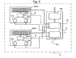
- Figure 2 shows the internal structure of the manager module MM according to the preferred embodiment of the invention.
- the centralized manager module MM is organized, for example, in sub-modules.
- One of the sub-modules is the MNG_CNS console, generally indicated as Management Console MNG_CNS;
- the Management Console MNG_CNS in the preferred embodiment, includes:
- the Goal Console GC, the Administrative Console AC and the Service Creation Console SCC are all coupled to the process description database PDB.
- the manager module MM comprises a Resource Allocator RA directly coupled to the Goal and Constraints Console GC and to the Re-Allocator Console RC.
- the Resource Allocator RA is also coupled, for example, to the Administrative Database ADB, as well as to the Performance Database PFM_DB holding platform performance data.
- the manager module MM further comprises, in the preferred embodiment, a Monitoring Data Acquisition Module MDM and a platform controller PC.
- the Monitoring Data Acquisition Module MDM is arranged for transferring performance data from the platform controller PC to the Performance Database PFM_DB.
- the Resource Allocator for example, may be coupled to an external interface module I for monitoring interactions among external OSSs and the management platform.
- the platform controller PC operates, in general, as a mediator between the manager module and the agents.
- the platform controller PC implements connection with the Master Agent MA (not shown) external to the Manager Module and with the Resource Allocator Module RA and is coupled with the Monitoring Console MC, the Monitoring Data Acquisition Module MDM, the Administrative Console AC and the Administrative Database ADB, so as with the Process Description Database PDB.
- the Goal and Constraints Console GC is intended for definition of business goals (e.g. Service Level Agreements or SLA) and constraints, jointly referred to as target data, associated to processes stored in the process description database PDB.
- business goals e.g. Service Level Agreements or SLA
- constraints jointly referred to as target data, associated to processes stored in the process description database PDB.
- Service Level Agreements or SLAs are a (contractual or simply agreed) quantification of the business process level quality.
- the SLAs are based on performance indicators (average execution time, percentiles, or others) and declare the values for these indicators to be guaranteed on the platform.
- a SLA can be described through a specific language (a "grammar") identifying a SLA goal (a performance indicator) and a SLA penalty clause (a SLA cost function based on the comparison between the SLA goal and the collected performance data), for example, an estimate of economical penalty of SLA violation.
- a SLA can be associated to a general business process (e.g. workflow) or to one of its specializations (identifiable in one or more workflow attributes), wherein the SLA for specializations typically overwrites the root business process ones, if any.
- Constraints concern data about resource utilization. They preferably include:
- the Resource Allocator RA (hereinafter Re-Allocator), according to a preferred embodiment of present invention, is centralized and manages allocation of resources to agents in order to adaptively control the platform. It is arranged to receive, for example:
- the Re-allocator RA preferably comprises two sub-modules: an Evaluate module and a Decide module, whose exemplary description and functionalities are given in the following of the specification.
- the Evaluate module is arranged to receive data about
- the Decide module is arranged to decide, on the basis of the previous information, if the platform is able to handle all the requests according to some criteria as will be specified later on. If the platform is not able to manage all the requests, the Decide module is arranged, for example, to send a warning message and decide which action can improve the situation. In particular, if resources are enough, but SLAs are not completely met, the Decide module is arranged to redistribute processing (i.e. workflow execution) across the platform. Preferably, these actions take care of the constraints and the priorities associated to the different instances of workflows.
- the Administrative Console AC is intended to define and monitor, for example, at least a set of the following:
- the Re-allocator Console RC is arranged for definition of resource reallocation policies, i.e. instruction of when and how re-allocate resources in order to optimize business goal satisfaction on the basis of business constraints and monitored data.
- the Re-allocator Console allows to enter policies both for centralized and distributed control. In particular, it allows definition of:
- the Monitoring Console MC is arranged for browsing monitoring information such as:
- the Monitoring Console MC enables to browse, in a hierarchical way, performances and resource utilization of workflows (in particular, every block of workflow). For every SLA, it is possible to issue reports about workflows which, due to a heavy utilization of resources, are worth being optimized. If other points of measure are set on different level of workflows, they are presented on the MC too. Besides, the MC shows information about billing, in terms of resources used by the workflows.
- the Service Creation Environment Console SCC is arranged for definition, creation and modification of the processes in the PDB, thus of every business functionality provided in the management platform. It is based on a graphical interface to facilitate this task. This console also allows the insertion of new monitoring points on the workflows.
- the data managed by the MM modules are also used to achieve a useful capacity planning by adding to the MM modules a Forecast Console and a Capacity Planning Module.
- the Forecast Console is arranged to set utilization forecasts in order to achieve a useful capacity planning activity. Input of this console are:
- the Capacity Planning Module is arranged to assure hardware resources over the time. It is arranged to receive inputs from the Forecast Console and other Consoles (the Goal & Constraints Console, the Administrative Console and the Re-Allocator Console) and to verify availability of resources. If resources are not enough, the Capacity Planning Module is arranged to warn an operator of the console about the amount of hardware needed to meet the expected increased trend. This module bases its analysis on a set of parameters including at least one of the following:
- Capacity Planning Module is based on uncertain data (especially, long term data) it is arranged mainly for information purposes. It may highlight future needs, but it does preferably not interact with the Resource Allocator RA.
- Figure 3 shows an example of the internal structure of a host machine including agent modules A and a control agent CA responsible for the overall performance of the host and the control of all the agents that run on that host.
- Each agent A includes at least a set of the following components:
- the control agent CA includes at least a set of the following components, preferably software implemented:
- control agents CA by their side, preferably have an important feature according to a preferred embodiment. They are able to actively manage the parallelism of their process threads (local optimization). The two capabilities of queue re-ordering and parallelism management joint together are the basis of the adaptive mechanism according to an aspect of the invention.
- the Resource Monitor RM, the Thread Controller TC and the Dispatcher D can be annexed to the agent module, for example if there are is a single agent module A on a host machine H.
- a preferred embodiment of the system of the invention is implemented using JADE (Java Agent Development framework) for implementing agents with mobility features, XPDL (XML Process Definition Language) for process definition, and an XPDL workflow engine as Shark.
- JADE Java Agent Development framework
- XPDL XML Process Definition Language
- Shark an XPDL workflow engine
- the Reallocator RA can be implemented as an expert rule-based system with functionalities of constraints processing, data manipulation and configuration changes. All the data, constraints and rules coming from the managed network, external systems, human knowledge and internal analysis constitute its knowledge base, which may be materially represented by an associated knowledge database.
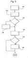
- the Re-Allocator module RA executes the Evaluate and Decide modules at predetermined intervals of analysis, which can be set on a case by case basis depending upon the context of the scenario.
- Reallocator gets data about process requests from external systems through bus B in order to evaluate the number of service/function requests forecasted for the subsequent time interval and maintains this information in the associated knowledge database.
- the Decide module activates the resource reallocation rules in order to find out the actions to be taken in order to achieve predetermined business goals in an optimised way.
- the resource allocator module At each interval T, the resource allocator module considers the number of queued requests and the number of forecast requests based on historical basis. It performs a first evaluation of the amount of available hardware resources (mainly CPU and RAM). These data are possibly tuned using actual measured data at the end of the interval, considering a "Background error correction", which will be described later.
- the collected information are correlated to the length and composition of the queues at a time t and to the number of requests expected (by forecast) during the interval [t, t+T] to calculate the total request of CPU power for the subsequent intervals, intended as a set comprising the following interval or a set of intervals located after a plurality of intervals.
- the total amount of CPU i.e. the requested computing power for the new interval (considering level and geographical constraints), is then compared to the available CPU power. If it is not enough, a warning (requesting new hardware) is generated to the console and priorities of workflows will determine how the load will be handled.
- the method and system according to the invention use a policy based on priorities, whereby there are different levels of priorities.
- the Decide module can manipulate priority queues to achieve business goals. To avoid starvation, if a workflow request spends too much time into a low-priority queue, its priority is automatically updated so that the request is moved to a higher priority queue.
- the management algorithm is based on an adaptive solution for improving the resource configuration at every step and trying to reach the best configuration with an incremental behavior.
- the results of the present approach are guaranteed by using an interval of analysis which is at least two or three times the average workflow execution time (a reasonable interval will depend on the context of the application and can vary from 5 minutes to 1 hour or more).
- a priority is associated to every execution of workflow, taking into consideration:
- any means to define and measure execution of functionalities can be used, for example CPU estimation with statistical techniques.
- the resource to be optimised is CPU load.
- top level workflows are services associated with an SLA characterized by a priority property, expressed in terms of percentage of workflows to be completed within a time t >> ⁇ T , where ⁇ T is the observation interval time.
- Last assumption is required in order to give the platform enough time to recalibrate within the period t.
- Top level workflows consist in a composition of many sub-workflows. All workflows have a priority property that affects their queue waiting time before execution and workflow CPU time slice.
- Input data are:
- the performance adaptation process is based on monitoring performed every ⁇ T time interval, which represents the minimum platform adaptation time.
- CpuTimeP g ⁇ wf ⁇ WF g ⁇ l wf ⁇ NEP wf g
- NSLA wfl1 In order to forecast if computational resources are enough to be SLA complaint, for each SLA defined on a first level workflow wfl1, the number of wfl1 to be executed in the subsequent ⁇ T in order to be SLA compliant, NSLA wfl1 is calculated:
- the methodology consists in various actions, at least some examples of which are described in the following, ordered by complexity:
- Actions d) and e) are based on a function that tries to minimize the cost impact of SLA penalties, defined through the Goal & Constraint Console GC.
- this methodology keeps into account the constraints on resources utilization, like the maximum amount of CPU time to be allocated for each workflows. This means that the priority of a workflow that is already using the maximum amount of reserved CPU time cannot be increased.
- an alternative possibility is that the agent collects at predetermined intervals (for example every five minutes) the number of "building block" executed and makes a correlation with the system resource utilization (for example CPU utilization).
- Multivariate regressive techniques are often employed to estimate performance of computer systems under overload conditions. This choice rests upon the analysis of the behaviour of a number of in-field OSS that were exercised beyond their capacity. The outcome was that most of the common performance metrics for OSS, such as CPU utilization, may be modeled by linear regression. System response time, for example, grows according to a moderate exponential law. Thus, a lower bound for predicting system performance may be obtained by a multivariate linear regression technique based on system resource data and workflow execution data.
- all the measures should be translated in an economical quantity in order to optimize the adaptation in a consistent way.
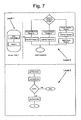
- Figure 6 shows, by way of example, the setup of a three-layers service provisioning scenario according to the invention, characterised by flexibility and scalability.
- the bottom layer agents are responsible for interaction with the network element and are called Resource Proxy and indicated RP1, RP2, RP3.
- a broadband service named "Offer 1" shall be delivered in a telecommunications network that includes access devices (e.g. an ADSL Equipment), an ATM backbone and BASs (Broadband Access Servers) in order to gain IP connectivity.
- access devices e.g. an ADSL Equipment
- ATM backbone e.g. an ATM backbone
- BASs Broadband Access Servers
- Examples of services offered by RP are configuration of ports, creation of cross-connections, modification of connection attributes. Each of them can include sequences of basic commands to be sent and/or received to/by the equipments.
- AA1, AA2, AA3 are the agents that manage, respectively, the Resource Proxy RP1 representing the image of the ADSL Equipment E (endpoint A of the end-to-end circuit), the Resource Proxy RP2 representing the image of the ATM Switch SW connected to the ADSL Equipment E and the Resource Proxy RP3 representing the image of the BAS (endpoint Z of the end-to-end circuit).
- Level 1 or top level workflow comprises two steps or tasks and is executed by Master Agent MA.
- the first one (ADSL Connectivity) requests execution of a level 2 workflow that is executed at the agent level (AA1, AA2, AA3) while the second one, i.e. the Mailbox task (not detailed in this example) can be performed by an external platform.
- the ADSL Connectivity Task is thus a Level 2 workflow that comprises a sequence of Level 3 workflows, technology and vendor dependent, that are executed at Resource Proxy Level (RP1, RP2, RP3).
- the level 3 workflows comprises sequences of the commands that must be performed on a communication network equipment by the Resource Proxy.
- An example of level 3 workflow is given in figure 7 by expanding level 2 workflow "Create ADSL Port Vendor A".
- the Monitoring Console MC highlights if there are problems on a particular Vendor or on a particular workflow.
- the Goal Console allows to define SLA on Offer1 and Offer2 with a SLA control rule and a related cost function. If the SLA on service “Offer2" is more important (for example the cost function associated to "Offer2" is equal to the number of seconds that exceed an average execution time of 1 second and the cost function associate to "Offer1" is equal to the number of second that exceed an average execution time of 4 second) then priority on “Offer2" grows faster than the priority of "Offer1". This means that when the hardware resource (e.g. CPU) are scarce with the same number of requests, the throughput of "Offer2" will be higher then the throughput of "Offer1".
- the hardware resource e.g. CPU
- the platform adjusts resource utilization to reach its target, be it a requirement set by an external operator or due to agent saturation.
Landscapes
- Engineering & Computer Science (AREA)
- Computer Networks & Wireless Communication (AREA)
- Signal Processing (AREA)
- Theoretical Computer Science (AREA)
- Computer Hardware Design (AREA)
- Software Systems (AREA)
- General Engineering & Computer Science (AREA)
- General Physics & Mathematics (AREA)
- Physics & Mathematics (AREA)
- Management, Administration, Business Operations System, And Electronic Commerce (AREA)
- Telephonic Communication Services (AREA)
- Financial Or Insurance-Related Operations Such As Payment And Settlement (AREA)
- Exchange Systems With Centralized Control (AREA)
- Mobile Radio Communication Systems (AREA)
- Multi Processors (AREA)
- Data Exchanges In Wide-Area Networks (AREA)
- Computer And Data Communications (AREA)
Claims (29)
- Verfahren zum Verwalten von Ressourcen für Telekommunikationsdienste und/oder -netzwerke, das das Abarbeiten von verteilten Agenten (A1, A2, A3) aufweist, die Process Engines (PE) zum Ausführen von Verwaltungsprozessen enthalten, mit den folgenden Schritten:Festlegen von einzuhaltenden Zieldaten, wobei die Zieldaten Ziele für die Abarbeitung von Prozessen durch die verteilten Agenten und Randbedingungen für die Ressourcennutzung beinhalten;Überwachen, mittels der in den verteilten Agenten enthaltenen Process Engines, der Prozessausführungen durch die verteilten Agenten (A1, A2, A3) und der Ressourcennutzung;Erfassen von Leistungsdaten, die für die Prozessausführungen und die Ressourcennutzung stehen;Vergleichen der erfassten Leistungsdaten mit den festgelegten Zieldaten;Aufstellen mindestens einer Penalty-Klausel auf Grund eines Vergleichs zwischen den erfassten Leistungsdaten der Agenten und den festgelegten Zieldaten undNeuzuteilen von Ressourcen für die Agenten (A1, A2, A3) für Prozessausfühnmgen durch Agenten (A1, A2, A3) auf Grund der mindestens einen aufgestellten Penalty-Klausel.
- Verfahren nach Anspruch 1, dadurch gekennzeichnet, dass der Schritt des Neuzuteilens von Ressourcen das Modifizieren von Prozessprioritäten an den verteilten Agenten (A1, A2, A3) aufweist.
- Verfahren nach Anspruch 1, dadurch gekennzeichnet, dass der Schritt des Neuzuteilens von Ressourcen das Ausführen eines Beurteilungsschritts und eines Entscheidungsschritts in festgelegten Kontroll-Intervallen aufweist, wobei
der Beurteilungsschritt die folgenden Schritte aufweist:Erfassen von Daten, die für die Prozessausfühnmgen und für die Anzahl von vorhergesagten Prozessausführungen für mindestens eines von aufeinanderfolgenden Kontroll-Intervallen stehen; undBeurteilen der von den Agenten angeforderten Ressourcen auf Grund der erfassten Daten undder Entscheidungsschritt die folgenden Schritte aufweist:Vergleichen der von jedem der Agenten (A1, A2, A3) angeforderten Ressourcen mit den verfügbaren Ressourcen undVerwenden von festgelegten Regeln für die Neuzuteilung von Ressourcen für die Agenten (A1, A2, A3), um die Ressourcennutzung unter den Agenten (A1, A2, A3) zu modifizieren und/oder Prozessprioritäten an den Agenten (A1, A2, A3) zu ändern und/oder Prozessausfdhrungen unter den Agenten (A1, A2, A3) neu zuzuteilen. - Verfahren nach einem der vorhergehenden Ansprüche, gekennzeichnet durch Speichern von Prozessbeschreibungen, die für Prozesse stehen, in einer Prozessbeschreibungs-Datenbank (process descriptions database; PDB), die mit den Process Engines (PE) assoziiert ist.
- Verfahren nach Anspruch 4, dadurch gekennzeichnet, dass die Prozessbeschreibungen Arbeitsabläufe und/oder Regeln beinhalten.
- Verfahren nach einem der vorhergehenden Ansprüche, das das Bereitstellen der Agenten (A1, A2, A3) auf hierarchischen Ebenen entsprechend einer Mehrebenen-Konfiguration von Agenten (A1, A2, A3) aufweist.
- Verfahren nach Anspruch 6, dadurch gekennzeichnet, dass die Prozessausführungen der Mehrebenen-Konfiguration von Agenten (A1, A2, A3) von einem zentralen Manager Modul (MM) zugewiesen werden.
- Verfahren nach Anspruch 7, dadurch gekennzeichnet, dass der Schritt des Erfassens von Leistungsdaten das Senden der Leistungsdaten an das zentrale Manager Modul (MM) und/oder an eine Vielzahl von lokalen Leistungssteueragenten (performance control agents; CA) aufweist, die mit den Agenten (A1, A2, A3) assoziiert sind.
- Verfahren nach Anspruch 7 mit dem folgenden Schritt: Bereitstellen mindestens eines Master Agent (MA) auf der oberen Ebene der Mehrebenen-Konfiguration von Agenten (A1, A2, A3), wobei der Master Agent (MA) Agenten (A1, A2, A3), die sich auf unteren Ebenen der Mehrebenen-Konfiguration befinden, mit Prozessausführungen beauftragt.
- Verfahren nach einem der vorhergehenden Ansprüche, das für jeden Agenten (A1, A2, A3) die folgenden Schritte aufweist:Einfügen einer Prozessausführungsanforderung in eine Mehrebenen-Prioritäts-Prozesswarteschlange (WFQ) entsprechend einem Prioritätskriterium undTerminieren der Prozessausführungen auf Grund der Mehrebenen-Prioritäts-Prozesswarteschlange (WFQ).
- Verfahren nach Anspruch 10, das das Terminieren von Prozessausführungen durch mindestens einen Process-Engine-Thread (THE, ..., THn) aufweist, der mit jedem Agenten assoziiert ist.
- Verfahren nach Anspruch 10, dadurch gekennzeichnet, dass die Prozessausführungsanforderungen in der Mehrebenen-Prioritäts-Prozesswarteschlange (WFQ) auf Grund eines Time-out-Kriteriums aktualisiert werden.
- Verfahren nach den Ansprüchen 8 und 11, dadurch gekennzeichnet, dass jeder Steueragent (CA) die Anzahl von Process-Engine-Threads (THE, ..., THn) und die Ressourcennutzung durch die Agenten steuert.
- Verfahren nach Anspruch 8, dadurch gekennzeichnet, dass
der Steueragent (CA) einen Lastausgleichs-Algorithmus zum Ermitteln der Last der Agenten abarbeitet und
jeder Agent (A1, A2, A3) Proxessausführungsanforderungen an andere Agenten (A1, A2, A3) auf Grund eines Kriteriums sendet, das zumindest eine Beurteilung der Last der Agenten umfasst, die von dem Steueragenten (CA) ermittelt worden ist. - Plattform zum Verwalten von Ressourcen für Telekommunikationsdienste und/oder -netzwerke, mit:einer Mehrzahl von verteilten Agenten (A1, A2, A3), die Process Engines (PE) enthalten, die die Ausführung von Verwaltungsprozessen (WF1, ..., WFn) verwalten können, wobei die in den verteilten Agenten enthaltenen Process Engines (PE) zum Überwachen der Prozessausführungen und der Ressourcennutzung durch die verteilten Agenten (A1, A2, A3) konfiguriert sind; undeinem zentralen Manager Modul (MM), das für die folgenden Schritte konfiguriert ist:Festlegen von Zieldaten, die von der Plattform einzuhalten sind, wobei die Zieldaten Ziele für die Prozessausführungen (WF1, ..., WFn) durch die verteilten Agenten und Randbedingungen für die Plattform-Ressourcennutzung beinhalten, die von der Plattform zu erfüllen sind;Erfassen von Leistungsdaten, die für die Prozessausführungen und für die Ressourcennutzung durch die verteilten Agenten (A1, A2, A3) stehen;Vergleichen der erfassten Leistungsdaten mit den festgelegten Zieldaten;Aufstellen mindestens einer Penalty-Klausel auf Grund eines Vergleichs zwischen den erfassten Leistungsdaten der Agenten und den festgelegten Zieldaten undNeuzuteilen von Ressourcen für die Agenten (A1, A2, A3) für Prozessausführungen durch Agenten (A1, A2, A3) auf Grund der mindestens einen aufgestellten Penalty-Klausel.
- Plattform nach Anspruch 15, dadurch gekennzeichnet, dass das zentrale Manager Modul (MM) ein Ressourcenzuteilungsmodul (resource allocator module; RA) mit den folgenden Modulen aufweist:einem Beurteilungsmodul, das für die folgenden Schritte konfiguriert ist:Erfassen von Daten, die für die Prozessausführungen und für die Anzahl von vorhergesagten Prozessausführungen für ein nachfolgendes Kontroll-Intervall stehen, undBeurteilen der von den Agenten angeforderten Ressourcen auf Grund der erfassten Daten; undeinem Entscheidungsmodul, das für die folgenden Schritte konfiguriert ist:Vergleichen der von jedem der Agenten (A1, A2, A3) angeforderten Ressourcen mit den verfügbaren Ressourcen undVerwenden von festgelegten Regeln für die Neuzuteilung von Ressourcen für die Agenten (A1, A2, A3), um die Ressourcennutzung unter den Agenten (A1, A2, A3) zu modifizieren und/oder Prozessprioritäten an den Agenten (A1, A2, A3) zu ändern und/oder Prozessausführungen unter den Agenten (A1, A2, A3) neu zuzuteilen.
- Plattform nach den Ansprüchen 15 bis 16, dadurch gekennzeichnet, dass das zentrale Manager Modul (MM) eine Prozessbeschreibungs-Datenbank (PDB) zum Speichern von Prozessbeschreibungen aufweist, die für Verhaltens- und Funktionsaspekte der Plattform stehen.
- Plattform nach Anspruch 17, dadurch gekennzeichnet, dass das zentrale Manager Modul (MM) weiterhin eine Service Creation Console (SCC) aufweist, die zum Definieren, Erzeugen und Modifizieren der Prozessbeschreibungen in der Prozessbeschreibungs-Datenbank (PDB) eingerichtet ist.
- Plattform nach Anspruch 17, dadurch gekennzeichnet, dass die Prozessbeschreibungen Arbeitsabläufe und/oder Regeln beinhalten.
- Plattform nach den Ansprüchen 15 bis 19, dadurch gekennzeichnet, dass
die Vielzahl von verteilten Agenten (A1, A2, A3) auf hierarchischen Ebenen entsprechend einer Mehrebenen-Konfiguration organisiert ist und
das zentrale Manager Modul (MM) zum Zuteilen von Prozessausführungen für die Mehrebenen-Konfiguration von Agenten konfiguriert ist. - Plattform nach den Ansprüchen 15 bis 20,
gekennzeichnet durch lokale Leistungssteueragenten (CA), die mit mindestens einer Gruppe von verteilten Agenten (A1, A2, A3) assoziiert sind, und
dadurch gekennzeichnet, dass die Process Engines (PE) Ressourcenüberwachungsmodule (resource monitor modules; RM) haben, die zum Senden der Leistungsdaten an das zentrale Manager Modul (MM) und/oder an die lokalen Leistungssteueragenten (CA) konfiguriert sind, die mit den Agenten (A1, A2, A3) assoziiert sind. - Plattform nach Anspruch 20, gekennzeichnet durch mindestens einen Master Agent (MA), der sich auf der oberen Ebene der Mehrebenen-Konfiguration von Agenten (A1, A2, A3) befindet und zum Beauftragen von Agenten (A1, A2, A3), die sich auf unteren Ebenen der Mehrebenen-Konfiguration befinden, mit Prozessausführungen konfiguriert ist.
- Plattform nach den Ansprüchen 15 bis 22, gekennzeichnet durch mindestens eine Verarbeitungsmaschine (H) mit mindestens einer Gruppe der Vielzahl von verteilten Agenten (A1, A2, A3).
- Plattform nach Anspruch 23, dadurch gekennzeichnet, dass mindestens ein lokaler Leistungssteueragent (CA) mit der mindestens einen Verarbeitungsmaschine (H) assoziiert ist.
- Plattform nach Anspruch 24, dadurch gekennzeichnet, dass der mindestens eine lokale Leistungssteueragent (CA) Folgendes aufweist:ein gemeinsames lokales Leistungsüberwachungsmodul (RM), das zum Erfassen von Leistungsdaten, die für die Ressourcennutzung und die Prozessausführung durch die Agenten (A1, A2, A3) stehen, und zum Senden der Leistungsdaten an das zentrale Manager Modul (MM) eingerichtet ist;einen mit dem Ressourcenüberwachungsmodul (RM) verbundenen gemeinsamen Thread Controller (TC), der zum Erzeugen von Process-Engine-Threads (TH1, ..., THn) zum Ausführen von Warteprozessen (WF1, ..., WFn) eingerichtet ist; undein gemeinsames Dispatcher-Modul (D), das mit den Process-Engine-Threads (TH1, ..., THn) verbunden ist und zum Senden von Prozessausführungsanforderungen an andere Agenten (A1, A2, A3) nach einem festgelegten Lastausgleichs-Algorithmus eingerichtet ist.
- Plattform nach Anspruch 15, dadurch gekennzeichnet, dass das Manager Modul (MM) ein Kapazitätsplanungsmodul aufweist, das zum Vorhersagen der Verfügbarkeit von Ressourcen in einem Kontroll-Intervall auf Grund der historischen Leistung und von Daten konfiguriert ist, die für die aktuelle Ressourcennutzung stehen.
- Plattform nach Anspruch 15, dadurch gekennzeichnet, dass das Manager Modul (MM) eine Administrative Console (AC) aufweist, die zum Definieren der Hardware-Konfiguration der Plattform und zum Definieren von Randbedingungen für Prozessausführungen konfiguriert ist.
- Telekommunikationsnetzwerk mit einer Plattform nach einem der Ansprüche 15 bis 27.
- Computerprogrammprodukt oder Computerprogrammsatz aus Computerprogrammprodukten, die in den Speicher mindestens eines Computers geladen werden können und Softwarecodeteile zum Ausführen der Schritte nach einem der Ansprüche 1 bis 14 aufweisen.
Applications Claiming Priority (1)
| Application Number | Priority Date | Filing Date | Title |
|---|---|---|---|
| PCT/EP2004/012224 WO2006045337A1 (en) | 2004-10-28 | 2004-10-28 | Method for managing resources in a platform for telecommunication service and/or network management, corresponding platform and computer program product therefor |
Publications (2)
| Publication Number | Publication Date |
|---|---|
| EP1806002A1 EP1806002A1 (de) | 2007-07-11 |
| EP1806002B1 true EP1806002B1 (de) | 2010-08-25 |
Family
ID=34959408
Family Applications (1)
| Application Number | Title | Priority Date | Filing Date |
|---|---|---|---|
| EP04822335A Active EP1806002B1 (de) | 2004-10-28 | 2004-10-28 | Verfahren zur verwaltung von betriebsmitteln in einer plattform für telekommunikationsdienst und/oder netzverwaltung, entsprechende plattform und computerprogrammprodukt dafür |
Country Status (11)
| Country | Link |
|---|---|
| US (1) | US8264971B2 (de) |
| EP (1) | EP1806002B1 (de) |
| JP (1) | JP2008519322A (de) |
| KR (1) | KR101096000B1 (de) |
| CN (1) | CN101084680B (de) |
| AT (1) | ATE479287T1 (de) |
| BR (1) | BRPI0419152B1 (de) |
| DE (1) | DE602004028877D1 (de) |
| ES (1) | ES2351604T3 (de) |
| IL (1) | IL182824A (de) |
| WO (1) | WO2006045337A1 (de) |
Cited By (1)
| Publication number | Priority date | Publication date | Assignee | Title |
|---|---|---|---|---|
| WO2015070588A1 (zh) * | 2013-11-12 | 2015-05-21 | 中兴通讯股份有限公司 | 用于电信网管系统的性能数据采集方法及服务器 |
Families Citing this family (68)
| Publication number | Priority date | Publication date | Assignee | Title |
|---|---|---|---|---|
| US20080034090A1 (en) * | 2005-09-29 | 2008-02-07 | Nortel Networks Limited | Tender-Bid Method and Architecture For Intelligent Network Resource Deployment |
| EP1973037B1 (de) | 2005-12-28 | 2012-08-29 | International Business Machines Corporation | Lastverteilung in einem client-server-system |
| GB0610532D0 (en) * | 2006-05-26 | 2006-07-05 | Abilisoft Ltd | Monitoring of network management systems |
| JP4240062B2 (ja) * | 2006-05-31 | 2009-03-18 | 日本電気株式会社 | 計算機システムおよび性能計測方法ならびに管理サーバ装置 |
| EP1916621A1 (de) * | 2006-10-26 | 2008-04-30 | Hewlett-Packard Development Company, L.P. | Anpassen von Computer-Netzwerken |
| US8160594B2 (en) * | 2006-12-28 | 2012-04-17 | Hitachi, Ltd. | Radio propagation estimating method and radio propagation estimating apparatus |
| US20080270653A1 (en) * | 2007-04-26 | 2008-10-30 | Balle Susanne M | Intelligent resource management in multiprocessor computer systems |
| JP2008282185A (ja) * | 2007-05-10 | 2008-11-20 | Hitachi Ltd | 物理条件が作業に影響する場合を支援するワークフローシステムおよび、それを用いた輸送方法および保守方法 |
| US20090006170A1 (en) * | 2007-06-26 | 2009-01-01 | Wachovia Corporation | Production center system |
| ATE450951T1 (de) | 2007-08-29 | 2009-12-15 | Alcatel Lucent | Verfahren zur zuweisung von ressourcen zur ausführung eines verwaltungsvorgangs in einem telekommunikationsnetz |
| US9210042B2 (en) * | 2007-09-14 | 2015-12-08 | Nec Europe Ltd. | Method and system for optimizing network performances |
| WO2009086326A1 (en) * | 2007-12-20 | 2009-07-09 | Akorri Networks, Inc. | Evaluating and predicting computer system performance using kneepoint analysis |
| US9977721B2 (en) | 2007-12-20 | 2018-05-22 | Netapp, Inc. | Evaluating and predicting computer system performance using kneepoint analysis |
| WO2009096519A1 (ja) * | 2008-01-31 | 2009-08-06 | Nec Corporation | フィードフォーワード制御方法、サービス提供品質制御装置、システム、プログラム及びその記録媒体 |
| US8112366B2 (en) * | 2008-09-30 | 2012-02-07 | Microsoft Corporation | Expert system and visualization for multi-server capacity management |
| US8656404B2 (en) * | 2008-10-16 | 2014-02-18 | Palo Alto Research Center Incorporated | Statistical packing of resource requirements in data centers |
| US10185646B2 (en) * | 2008-12-16 | 2019-01-22 | Red Hat, Inc. | Getting performance saturation point of an event driven system |
| WO2010089900A1 (en) * | 2009-02-05 | 2010-08-12 | Nec Corporation | Method, system and program for deadline constrained task admission control and scheduling using genetic approach |
| WO2010131778A1 (ja) * | 2009-05-15 | 2010-11-18 | 日本電気株式会社 | ワークフロー監視制御システム、監視制御方法および監視制御プログラム |
| CN101931609B (zh) * | 2009-06-22 | 2014-07-30 | Sap股份公司 | 多租户数据库应用的遵守服务等级协议的布局 |
| US10185594B2 (en) * | 2009-10-29 | 2019-01-22 | International Business Machines Corporation | System and method for resource identification |
| US8260958B2 (en) * | 2010-02-24 | 2012-09-04 | F5 Networks, Inc. | Reducing energy consumption of servers |
| US8255529B2 (en) * | 2010-02-26 | 2012-08-28 | Red Hat, Inc. | Methods and systems for providing deployment architectures in cloud computing environments |
| JP5471859B2 (ja) * | 2010-06-10 | 2014-04-16 | 富士通株式会社 | 解析プログラム、解析方法、および解析装置 |
| JP5414663B2 (ja) * | 2010-12-24 | 2014-02-12 | 株式会社東芝 | サービス提供システム、装置及びプログラム |
| US20120278513A1 (en) * | 2011-02-01 | 2012-11-01 | Michel Prevost | Priority scheduling for multi-channel context aware communication technology |
| JP5569424B2 (ja) * | 2011-02-14 | 2014-08-13 | 富士通株式会社 | 更新装置、更新方法、および更新プログラム |
| US8630959B2 (en) | 2011-02-23 | 2014-01-14 | International Business Machines Corporation | Determining costs for workflows |
| US20120215582A1 (en) * | 2011-02-23 | 2012-08-23 | International Business Machines Corporation | Executing workflows based on service level agreements |
| WO2012171186A1 (zh) | 2011-06-15 | 2012-12-20 | 华为技术有限公司 | 业务处理资源的调度方法以及装置 |
| US8539074B2 (en) * | 2011-07-19 | 2013-09-17 | International Business Machines Corporation | Prioritizing data packets associated with applications running in a networked computing environment |
| CN102915254B (zh) * | 2011-08-02 | 2018-04-06 | 中兴通讯股份有限公司 | 任务管理方法及装置 |
| US8660949B2 (en) | 2011-09-09 | 2014-02-25 | Sap Ag | Method and system for working capital management |
| US8769089B2 (en) * | 2011-11-15 | 2014-07-01 | International Business Machines Corporation | Distributed application using diagnostic heartbeating |
| US8874974B2 (en) | 2011-11-15 | 2014-10-28 | International Business Machines Corporation | Synchronizing a distributed communication system using diagnostic heartbeating |
| US8756453B2 (en) | 2011-11-15 | 2014-06-17 | International Business Machines Corporation | Communication system with diagnostic capabilities |
| US8903893B2 (en) | 2011-11-15 | 2014-12-02 | International Business Machines Corporation | Diagnostic heartbeating in a distributed data processing environment |
| US9244796B2 (en) | 2011-11-15 | 2016-01-26 | International Business Machines Corporation | Diagnostic heartbeat throttling |
| CN103491115A (zh) * | 2012-06-12 | 2014-01-01 | 华为软件技术有限公司 | 资源调度方法、装置及系统 |
| US10032136B1 (en) * | 2012-07-30 | 2018-07-24 | Verint Americas Inc. | System and method of scheduling work within a workflow with defined process goals |
| GB2507338A (en) | 2012-10-26 | 2014-04-30 | Ibm | Determining system topology graph changes in a distributed computing system |
| US9154398B1 (en) * | 2013-03-01 | 2015-10-06 | Emc Corporation | Method and system for identifying root causes of application underachievement in a virtually provisioned environment |
| CN103718633B (zh) | 2013-08-30 | 2017-11-17 | 华为技术有限公司 | 资源分配方法、装置及系统 |
| US9998332B2 (en) * | 2013-11-15 | 2018-06-12 | Massachusetts Institute Of Technology | Signal-flow architecture for cooperative control and resource allocation |
| CN105873070B (zh) | 2015-01-20 | 2020-04-10 | 中兴通讯股份有限公司 | 一种授权共享接入系统干扰自适应发现方法与装置 |
| JP6425561B2 (ja) * | 2015-01-23 | 2018-11-21 | Kddi株式会社 | 分散型ネットワーク管理システム、ネットワーク管理装置、ネットワーク装置、分散型ネットワーク管理方法およびプログラム |
| CN104573993A (zh) * | 2015-01-29 | 2015-04-29 | 北京京东尚科信息技术有限公司 | 多流程执行方法和系统 |
| EP3118784A1 (de) | 2015-07-14 | 2017-01-18 | Tata Consultancy Services Limited | Verfahren und system zur aktivierung von dynamischer kapazitätsplanung |
| US10332018B2 (en) | 2016-03-01 | 2019-06-25 | International Business Machines Corporation | Service level agreement risk analysis with exogenous architecture |
| CN105824703B (zh) * | 2016-03-30 | 2019-03-29 | 联想(北京)有限公司 | 一种线程管理方法和线程管理器 |
| US10374872B2 (en) * | 2016-05-24 | 2019-08-06 | Apstra, Inc. | Configuring system resources for different reference architectures |
| AU2017280347B2 (en) | 2016-06-24 | 2022-07-07 | Schneider Electric Systems Usa, Inc. | Methods, systems and apparatus to dynamically facilitate boundaryless, high availability system management |
| US10698954B2 (en) * | 2016-06-30 | 2020-06-30 | Facebook, Inc. | Computation platform agnostic data classification workflows |
| JP6717092B2 (ja) | 2016-07-14 | 2020-07-01 | 富士通株式会社 | 制御装置および制御装置における処理方法 |
| EP3270598A3 (de) * | 2016-07-15 | 2018-03-21 | Intraway R&D S.A. | System und verfahren zur bereitstellung von betrugskontrolle |
| US10545951B1 (en) | 2016-12-15 | 2020-01-28 | Amazon Technologies, Inc. | Workflow dependency management system |
| US11356315B2 (en) | 2018-03-28 | 2022-06-07 | Intel Corporation | Methods and apparatus to dynamically control devices based on distributed data |
| US10572316B2 (en) * | 2018-05-14 | 2020-02-25 | International Business Machines Corporation | Adaptable pages, widgets and features based on real time application performance |
| JP7155605B2 (ja) * | 2018-05-22 | 2022-10-19 | 富士フイルムビジネスイノベーション株式会社 | 情報処理装置及びプログラム |
| US10990441B2 (en) * | 2018-07-31 | 2021-04-27 | Nutanix, Inc. | Multi-level job processing queues |
| JP7410379B2 (ja) * | 2019-11-27 | 2024-01-10 | 富士通株式会社 | 資源使用量予測方法および資源使用量予測プログラム |
| US11824784B2 (en) | 2019-12-20 | 2023-11-21 | Intel Corporation | Automated platform resource management in edge computing environments |
| WO2021164857A1 (en) * | 2020-02-18 | 2021-08-26 | Telefonaktiebolaget Lm Ericsson (Publ) | Dynamic resource dimensioning for service assurance |
| JP2022021026A (ja) * | 2020-07-21 | 2022-02-02 | キオクシア株式会社 | メモリシステムおよびコマンドをフェッチする方法 |
| KR102427473B1 (ko) * | 2020-09-29 | 2022-08-01 | 한국전자기술연구원 | 마이크로 데이터센터내 가용 자원상태 기반 워크로드 예측 정확도 증가 방법 |
| US20220164235A1 (en) * | 2020-11-20 | 2022-05-26 | Okta, Inc. | Server-Based Workflow Management Using Priorities |
| US20220318067A1 (en) * | 2021-04-06 | 2022-10-06 | Intuit Inc. | Orchestration layer for user defined automation workflows |
| WO2024005681A1 (en) * | 2022-07-01 | 2024-01-04 | Telefonaktiebolaget Lm Ericsson (Publ) | Method and system for system optimization using service allocation weighting factors |
Family Cites Families (10)
| Publication number | Priority date | Publication date | Assignee | Title |
|---|---|---|---|---|
| US6243396B1 (en) * | 1995-08-15 | 2001-06-05 | Broadcom Eireann Research Limited | Communications network management system |
| BR9911503A (pt) * | 1998-06-25 | 2001-03-20 | Ericsson Telefon Ab L M | Sistema de administração de serviço de operações e manutenção de telecomunicações |
| AU5724799A (en) * | 1998-09-25 | 2000-04-17 | Soma Networks, Inc. | Method and system for negotiating telecommunication resources |
| WO2001002973A1 (en) | 1999-07-02 | 2001-01-11 | Covad Communications Group, Inc. | Process fulfillment systems and methods using distributed workflow management architecture |
| US6516337B1 (en) * | 1999-10-14 | 2003-02-04 | Arcessa, Inc. | Sending to a central indexing site meta data or signatures from objects on a computer network |
| JP3664021B2 (ja) * | 2000-01-05 | 2005-06-22 | 日本電気株式会社 | サービスレベルによる資源割当方式 |
| US7051098B2 (en) * | 2000-05-25 | 2006-05-23 | United States Of America As Represented By The Secretary Of The Navy | System for monitoring and reporting performance of hosts and applications and selectively configuring applications in a resource managed system |
| US6823382B2 (en) * | 2001-08-20 | 2004-11-23 | Altaworks Corporation | Monitoring and control engine for multi-tiered service-level management of distributed web-application servers |
| JP3772713B2 (ja) * | 2001-09-12 | 2006-05-10 | 日本電気株式会社 | プライオリティ動的制御方式、プライオリティ動的制御方法およびプライオリティ動的制御用プログラム |
| US7322034B2 (en) | 2002-06-14 | 2008-01-22 | Hewlett-Packard Development Company, L.P. | Method and system for dynamically allocating computer system resources |
-
2004
- 2004-10-28 CN CN2004800446483A patent/CN101084680B/zh active Active
- 2004-10-28 EP EP04822335A patent/EP1806002B1/de active Active
- 2004-10-28 AT AT04822335T patent/ATE479287T1/de not_active IP Right Cessation
- 2004-10-28 DE DE602004028877T patent/DE602004028877D1/de active Active
- 2004-10-28 US US11/666,509 patent/US8264971B2/en active Active
- 2004-10-28 JP JP2007538274A patent/JP2008519322A/ja not_active Withdrawn
- 2004-10-28 ES ES04822335T patent/ES2351604T3/es active Active
- 2004-10-28 KR KR1020077011953A patent/KR101096000B1/ko active IP Right Grant
- 2004-10-28 BR BRPI0419152-8A patent/BRPI0419152B1/pt active IP Right Grant
- 2004-10-28 WO PCT/EP2004/012224 patent/WO2006045337A1/en active Application Filing
-
2007
- 2007-04-26 IL IL182824A patent/IL182824A/en active IP Right Grant
Cited By (1)
| Publication number | Priority date | Publication date | Assignee | Title |
|---|---|---|---|---|
| WO2015070588A1 (zh) * | 2013-11-12 | 2015-05-21 | 中兴通讯股份有限公司 | 用于电信网管系统的性能数据采集方法及服务器 |
Also Published As
| Publication number | Publication date |
|---|---|
| CN101084680B (zh) | 2012-03-14 |
| EP1806002A1 (de) | 2007-07-11 |
| KR101096000B1 (ko) | 2011-12-19 |
| WO2006045337A1 (en) | 2006-05-04 |
| US20090122706A1 (en) | 2009-05-14 |
| IL182824A (en) | 2011-12-29 |
| ES2351604T3 (es) | 2011-02-08 |
| BRPI0419152B1 (pt) | 2018-02-06 |
| JP2008519322A (ja) | 2008-06-05 |
| DE602004028877D1 (de) | 2010-10-07 |
| BRPI0419152A (pt) | 2008-01-22 |
| KR20070084594A (ko) | 2007-08-24 |
| IL182824A0 (en) | 2007-08-19 |
| ATE479287T1 (de) | 2010-09-15 |
| US8264971B2 (en) | 2012-09-11 |
| CN101084680A (zh) | 2007-12-05 |
Similar Documents
| Publication | Publication Date | Title |
|---|---|---|
| EP1806002B1 (de) | Verfahren zur verwaltung von betriebsmitteln in einer plattform für telekommunikationsdienst und/oder netzverwaltung, entsprechende plattform und computerprogrammprodukt dafür | |
| US11656915B2 (en) | Virtual systems management | |
| Appleby et al. | Oceano-SLA based management of a computing utility | |
| KR100570141B1 (ko) | 복수의 애플리케이션 레벨 사용자를 위한 접속 제공 방법, 시스템, 및 기록 매체 | |
| US10678602B2 (en) | Apparatus, systems and methods for dynamic adaptive metrics based application deployment on distributed infrastructures | |
| EP2667541B1 (de) | Konnektivitätsdienst-Orchestrator | |
| US6349325B1 (en) | Prioritized agent-based hierarchy structure for handling performance metrics data in a telecommunication management system | |
| US20060294238A1 (en) | Policy-based hierarchical management of shared resources in a grid environment | |
| US20060218551A1 (en) | Jobstream planner considering network contention & resource availability | |
| Antonescu et al. | Dynamic topology orchestration for distributed cloud-based applications | |
| Sun et al. | Rose: Cluster resource scheduling via speculative over-subscription | |
| US9607275B2 (en) | Method and system for integration of systems management with project and portfolio management | |
| US8972579B2 (en) | Resource sharing in computer clusters according to objectives | |
| Kecskemeti et al. | Facilitating self-adaptable Inter-Cloud management | |
| JP5670290B2 (ja) | 通信サービスのためのプロセスの実行のためのリソースを管理する方法、システム及びコンピュータ・プログラム | |
| Macías et al. | Enforcing service level agreements using an economically enhanced resource manager | |
| Sohani et al. | Fault tolerance using self-healing SLA and load balanced dynamic resource provisioning in cloud computing | |
| Johnston-Watt | Under New Management: Autonomic computing is revolutionizing the way we manage complex systems. | |
| Magaña et al. | Autonomic management architecture for flexible grid services deployment based on policies | |
| Roy et al. | Implementation of a resource broker for efficient resource management in grid environment | |
| De Sarkar et al. | Achieving guaranteed performance on computational Grid | |
| Merseguer Hernáiz | Extra Functional Properties Evaluation of Self-managed Software Systems with Formal Methods | |
| Panahi | A middleware architecture for service-oriented systems in support of accountability and predictability | |
| Anastasi | Quality of Service Management in Service Oriented Architectures | |
| Meyler | Distributed Coordination of Policy Execution across Autonomous Elements |
Legal Events
| Date | Code | Title | Description |
|---|---|---|---|
| PUAI | Public reference made under article 153(3) epc to a published international application that has entered the european phase |
Free format text: ORIGINAL CODE: 0009012 |
|
| 17P | Request for examination filed |
Effective date: 20070430 |
|
| AK | Designated contracting states |
Kind code of ref document: A1 Designated state(s): AT BE BG CH CY CZ DE DK EE ES FI FR GB GR HU IE IT LI LU MC NL PL PT RO SE SI SK TR |
|
| DAX | Request for extension of the european patent (deleted) | ||
| 17Q | First examination report despatched |
Effective date: 20080221 |
|
| GRAP | Despatch of communication of intention to grant a patent |
Free format text: ORIGINAL CODE: EPIDOSNIGR1 |
|
| GRAS | Grant fee paid |
Free format text: ORIGINAL CODE: EPIDOSNIGR3 |
|
| GRAA | (expected) grant |
Free format text: ORIGINAL CODE: 0009210 |
|
| AK | Designated contracting states |
Kind code of ref document: B1 Designated state(s): AT BE BG CH CY CZ DE DK EE ES FI FR GB GR HU IE IT LI LU MC NL PL PT RO SE SI SK TR |
|
| REG | Reference to a national code |
Ref country code: GB Ref legal event code: FG4D |
|
| REG | Reference to a national code |
Ref country code: CH Ref legal event code: EP |
|
| REG | Reference to a national code |
Ref country code: IE Ref legal event code: FG4D |
|
| REF | Corresponds to: |
Ref document number: 602004028877 Country of ref document: DE Date of ref document: 20101007 Kind code of ref document: P |
|
| REG | Reference to a national code |
Ref country code: NL Ref legal event code: VDEP Effective date: 20100825 |
|
| PG25 | Lapsed in a contracting state [announced via postgrant information from national office to epo] |
Ref country code: FI Free format text: LAPSE BECAUSE OF FAILURE TO SUBMIT A TRANSLATION OF THE DESCRIPTION OR TO PAY THE FEE WITHIN THE PRESCRIBED TIME-LIMIT Effective date: 20100825 Ref country code: AT Free format text: LAPSE BECAUSE OF FAILURE TO SUBMIT A TRANSLATION OF THE DESCRIPTION OR TO PAY THE FEE WITHIN THE PRESCRIBED TIME-LIMIT Effective date: 20100825 |
|
| REG | Reference to a national code |
Ref country code: ES Ref legal event code: FG2A Effective date: 20110127 |
|
| PG25 | Lapsed in a contracting state [announced via postgrant information from national office to epo] |
Ref country code: SI Free format text: LAPSE BECAUSE OF FAILURE TO SUBMIT A TRANSLATION OF THE DESCRIPTION OR TO PAY THE FEE WITHIN THE PRESCRIBED TIME-LIMIT Effective date: 20100825 Ref country code: PL Free format text: LAPSE BECAUSE OF FAILURE TO SUBMIT A TRANSLATION OF THE DESCRIPTION OR TO PAY THE FEE WITHIN THE PRESCRIBED TIME-LIMIT Effective date: 20100825 Ref country code: CY Free format text: LAPSE BECAUSE OF FAILURE TO SUBMIT A TRANSLATION OF THE DESCRIPTION OR TO PAY THE FEE WITHIN THE PRESCRIBED TIME-LIMIT Effective date: 20100825 Ref country code: PT Free format text: LAPSE BECAUSE OF FAILURE TO SUBMIT A TRANSLATION OF THE DESCRIPTION OR TO PAY THE FEE WITHIN THE PRESCRIBED TIME-LIMIT Effective date: 20101227 Ref country code: BG Free format text: LAPSE BECAUSE OF FAILURE TO SUBMIT A TRANSLATION OF THE DESCRIPTION OR TO PAY THE FEE WITHIN THE PRESCRIBED TIME-LIMIT Effective date: 20101125 |
|
| PG25 | Lapsed in a contracting state [announced via postgrant information from national office to epo] |
Ref country code: SE Free format text: LAPSE BECAUSE OF FAILURE TO SUBMIT A TRANSLATION OF THE DESCRIPTION OR TO PAY THE FEE WITHIN THE PRESCRIBED TIME-LIMIT Effective date: 20100825 Ref country code: GR Free format text: LAPSE BECAUSE OF FAILURE TO SUBMIT A TRANSLATION OF THE DESCRIPTION OR TO PAY THE FEE WITHIN THE PRESCRIBED TIME-LIMIT Effective date: 20101126 Ref country code: BE Free format text: LAPSE BECAUSE OF FAILURE TO SUBMIT A TRANSLATION OF THE DESCRIPTION OR TO PAY THE FEE WITHIN THE PRESCRIBED TIME-LIMIT Effective date: 20100825 Ref country code: NL Free format text: LAPSE BECAUSE OF FAILURE TO SUBMIT A TRANSLATION OF THE DESCRIPTION OR TO PAY THE FEE WITHIN THE PRESCRIBED TIME-LIMIT Effective date: 20100825 |
|
| PG25 | Lapsed in a contracting state [announced via postgrant information from national office to epo] |
Ref country code: DK Free format text: LAPSE BECAUSE OF FAILURE TO SUBMIT A TRANSLATION OF THE DESCRIPTION OR TO PAY THE FEE WITHIN THE PRESCRIBED TIME-LIMIT Effective date: 20100825 |
|
| PG25 | Lapsed in a contracting state [announced via postgrant information from national office to epo] |
Ref country code: SK Free format text: LAPSE BECAUSE OF FAILURE TO SUBMIT A TRANSLATION OF THE DESCRIPTION OR TO PAY THE FEE WITHIN THE PRESCRIBED TIME-LIMIT Effective date: 20100825 Ref country code: RO Free format text: LAPSE BECAUSE OF FAILURE TO SUBMIT A TRANSLATION OF THE DESCRIPTION OR TO PAY THE FEE WITHIN THE PRESCRIBED TIME-LIMIT Effective date: 20100825 Ref country code: EE Free format text: LAPSE BECAUSE OF FAILURE TO SUBMIT A TRANSLATION OF THE DESCRIPTION OR TO PAY THE FEE WITHIN THE PRESCRIBED TIME-LIMIT Effective date: 20100825 Ref country code: CZ Free format text: LAPSE BECAUSE OF FAILURE TO SUBMIT A TRANSLATION OF THE DESCRIPTION OR TO PAY THE FEE WITHIN THE PRESCRIBED TIME-LIMIT Effective date: 20100825 Ref country code: MC Free format text: LAPSE BECAUSE OF NON-PAYMENT OF DUE FEES Effective date: 20101031 |
|
| REG | Reference to a national code |
Ref country code: CH Ref legal event code: PL |
|
| PLBE | No opposition filed within time limit |
Free format text: ORIGINAL CODE: 0009261 |
|
| STAA | Information on the status of an ep patent application or granted ep patent |
Free format text: STATUS: NO OPPOSITION FILED WITHIN TIME LIMIT |
|
| PG25 | Lapsed in a contracting state [announced via postgrant information from national office to epo] |
Ref country code: LI Free format text: LAPSE BECAUSE OF NON-PAYMENT OF DUE FEES Effective date: 20101031 Ref country code: CH Free format text: LAPSE BECAUSE OF NON-PAYMENT OF DUE FEES Effective date: 20101031 |
|
| 26N | No opposition filed |
Effective date: 20110526 |
|
| REG | Reference to a national code |
Ref country code: DE Ref legal event code: R097 Ref document number: 602004028877 Country of ref document: DE Effective date: 20110526 |
|
| PG25 | Lapsed in a contracting state [announced via postgrant information from national office to epo] |
Ref country code: IE Free format text: LAPSE BECAUSE OF NON-PAYMENT OF DUE FEES Effective date: 20101028 |
|
| PG25 | Lapsed in a contracting state [announced via postgrant information from national office to epo] |
Ref country code: HU Free format text: LAPSE BECAUSE OF FAILURE TO SUBMIT A TRANSLATION OF THE DESCRIPTION OR TO PAY THE FEE WITHIN THE PRESCRIBED TIME-LIMIT Effective date: 20110226 Ref country code: LU Free format text: LAPSE BECAUSE OF NON-PAYMENT OF DUE FEES Effective date: 20101028 |
|
| PG25 | Lapsed in a contracting state [announced via postgrant information from national office to epo] |
Ref country code: TR Free format text: LAPSE BECAUSE OF FAILURE TO SUBMIT A TRANSLATION OF THE DESCRIPTION OR TO PAY THE FEE WITHIN THE PRESCRIBED TIME-LIMIT Effective date: 20100825 |
|
| REG | Reference to a national code |
Ref country code: FR Ref legal event code: PLFP Year of fee payment: 12 |
|
| REG | Reference to a national code |
Ref country code: FR Ref legal event code: PLFP Year of fee payment: 13 |
|
| REG | Reference to a national code |
Ref country code: FR Ref legal event code: PLFP Year of fee payment: 14 |
|
| REG | Reference to a national code |
Ref country code: FR Ref legal event code: PLFP Year of fee payment: 15 |
|
| P01 | Opt-out of the competence of the unified patent court (upc) registered |
Effective date: 20230529 |
|
| P02 | Opt-out of the competence of the unified patent court (upc) changed |
Effective date: 20230602 |
|
| PGFP | Annual fee paid to national office [announced via postgrant information from national office to epo] |
Ref country code: GB Payment date: 20231027 Year of fee payment: 20 |
|
| PGFP | Annual fee paid to national office [announced via postgrant information from national office to epo] |
Ref country code: ES Payment date: 20231102 Year of fee payment: 20 |
|
| PGFP | Annual fee paid to national office [announced via postgrant information from national office to epo] |
Ref country code: IT Payment date: 20231023 Year of fee payment: 20 Ref country code: FR Payment date: 20231025 Year of fee payment: 20 Ref country code: DE Payment date: 20231027 Year of fee payment: 20 |